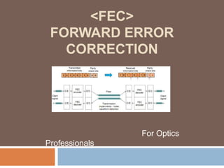
FEC-Forward Error Correction for Optics Professionals
•Download as PPTX, PDF•
3 likes•4,415 views

FEC-Forward Error Correction for Optics Professionals

Recommended
More Related Content
What's hot
What's hot (20)
Viewers also liked
Viewers also liked (20)
Similar to FEC-Forward Error Correction for Optics Professionals
Similar to FEC-Forward Error Correction for Optics Professionals (20)
More from MapYourTech
More from MapYourTech (20)
Recently uploaded
Recently uploaded (20)
FEC-Forward Error Correction for Optics Professionals
- 2. What is FEC? Forward Error Correction is the addition/interleaving of redundancy in a data stream allowing for correction of errors during reception of data without retransmission. FEC is a bandwidth efficient solution to increasing the BER. No need for retransmission. Based on highly complex mathematical field known as sets and finite field theory. Provides increased gain which can be DIRECTLY applied to the optical link budget FEC decreases the BER FEC is a bandwidth efficient solution to improving the BER. Allows correction without retransmission Allows decreased receiver cost for equivalent performance
- 3. What is FEC..contd FEC is a coding technology widely used in communication systems. Using a classical block code as an example, the FEC encoder at the transmit end uses kilo bits of information as a block code. During the encoding, FEC adds n-k redundant check bits to the information bits, constructing an n-bit codeword. After the codeword is transmitted to the receive end over a channel, the FEC decoder detects and corrects bit errors during decoding – if the errors are within the correction range. In this manner, FEC prevents interference from channel transmission and improves the reliability of an optical communication system. This shows that FEC can efficiently reduce the system BER with only a small number of redundant overhead bits, thus extending the transmission distance and reducing system costs.
- 4. What is FEC..contd FEC ensures reliable transmission As the basic bearer technology of optical communication systems, WDM has seen a rapid expansion in capacity alongside a similarly large increase in network traffic. During this expansion, every increase in the rate of a single wavelength has brought about a significant advance in communication technology: The increase from 2.5G to 10G wavelengths resulted in an evolution from direct modulation to external modulation and the use of DCMs for fiber dispersion compensation. The increase from 10G to 40G wavelengths marked a transition from OOK modulation to PSK modulation. The increase from 40G to 100G brought about the introduction of DSP-enabled coherent communication technology, in which analog-to-digital converters (ADCs) work at a rate higher than 56Gbit/s. As WDM technology advanced, forward error correction (FEC) took on a key role in ensuring reliable transmission of information and gradually became a mainstream technology essential for optical communication systems. FEC technology for fiber communication has also experienced several generations of evolution
- 5. What is FEC? (cont.) W/Errors 1. Xmitter Sends Message “The Quick Brown Fox …” Error Environment Data: “The Quicx Wrown Fox …” 1. Receiver receives data in error Error Environment Ist pass Data: “The Quicx Wrown Fox …” 1. Receiver receives data in error 2. Requests resend data 3. Receives error Data Received: “The Quicx Wrown Fox …” ARQ 1. Xmitter Sends Message “The Quick Brown Fox …” 2. Xmitter receives request for retransmission 3. Resends data 1. Xmitter Sends Message “The Quick Brown Fox …(FEC bits)” Error Environment 2nd pass Data: “The Quick Brown Fox …” Data Received: “The Quick Brown Fox …” free data FEC Error Environment Data: “The Quicx Wrown Fox …(FEC bits)” 1. Receiver receives Error’d data 2. Using FEC bits/bytes Corrects data Data Received: “The Quick Brown Fox …”
- 6. ABSTRACT The optical signals undergo quality degradation during transmission, which may lead the receiver into misjudging “1” for “0” signal or “0” for “1” signal. The Forward Error Correction (FEC) adds the parity bits during coding by the transmitter so that the receiver can correct the error bits in the code stream by calculating the parity bits. The FEC technology is originally used in the submarine cable system for ultra-long haul transmission. But with the development of terrestrial optical communication system and increase of single-channel rate, the FEC will become one of the optimal choices to lower the OSNR of equipment and networking cost as well. According to the latest ITU-T G.709 and G.975, the FEC technology is introduced for STM-16 services and services at higher rates currently to ensure the reliability of data transmission and greatly extend the transmission distance. Therefore, the FEC technology has already becomes a key technology in optical communication development and also one of the hot issues in optical communications.
- 7. Generation of FEC Along with the rapid development of optical communication technologies and continual increase in the capacity and rate of communication networks, the transmission distance (in the case that no electrical regenerators are used) is greatly affected by the defects in fiber transmission, such as group velocity dispersion (GVD), polarization mode dispersion (PMD), and attenuation. When no FEC technology is used and the signal rate is increased to 10 Gbit/s or even higher, the transmission distance without electrical regenerators turns too short to reach a practical length. Currently, the effective technologies available to expand capacity and extend communication distance are as follows: Wavelength division multiplexing (WDM) Erbium doped fiber amplifier (EDFA) High power laser Dispersion compensation fiber (DCF) Forward error correction (FEC) Introduction of EDFA can overcome the power budget problem. However, the inherent defects of EDFA may bring new problems, such as the decreasing of OSNR because of ASE noises. If the output optical power is increased too greatly, some negative impacts, such as non-linear effects, may be brought. To further extend the transmission distance and improve the receiver sensitivity of the system as well as the system requirement on input OSNR, the FEC needs to be introduced.
- 8. Some FEC Terminology FEC Frame = frame of bits/bytes which includes all information(k), redundancy(check bits), framing bits/bytes. For SONET/SDH frames, the FEC frame will always be smaller. t = Error correction factor. Number of bytes/bits that can be corrected m = symbol size (Reed Solomon Codes). Smallest correctable entity. n = Code word size. Size of FEC frame including redundant check bits/bytes. k = Information word size. This is the raw information (SONET/SDH/ATM/etc). Check bits = redundant bits appended/inserted to/ito FEC frame to allow forward error correction. Produced by the encoder.
- 9. Some FEC Terminology…contd Encoder = device responsible for determining the necessary check bits and forming the FEC frame. Decoder = device responsible for utilizing check bits to correct errors (within the error correction factor) in an FEC frame, including errors in the check bits. Burst Error = A consecutive group of symbols(m) in error is a single FEC frame. Interleaving/Interleave factor - A method for increasing the burst error handling capability of a particular FEC code. Interleave factor is the number of symbols interleaved. Error Multiplication = Increasing the error rate by attempting to correct beyond the error correction factor In-Band FEC = Code is contained within band and protocol constraints of the carrier stream. E.g., SONET in band utilizes un-used overhed bytes for check bit info. No Clock increase. Out-of-Band FEC = Code encapsulates the entire data stream and appends/inserts additional information to the carrier stream. Clock rate increase. Overhead/Efficiency - For out-of-band codes, the required additional bits/bytes to support the error correction factor of the code. Maximum usable today in OC-48 and OC-192 systems is about 8%.
- 10. Some FEC Terminology (cont) Typical “Out-of-Band” frame structure Frame Byte Data to be corrected (portion of SONET/SDH frame) Check Byte 1 Check Byte 2 Check Byte 3 Check Byte 4 Typical “In- Band” frame structure Check Byte 1 Check Byte 2 ... SONET SONET SONET A1 A1/A2 A2 ... Check Byte 3 Check SONET Byte 4 J0 Additional SONET Overhead and SONET Payload IF FEC Code is a (255,251) Reed Solomon code then: m = 8 (symbol size) n = 255 (code word size) k = 251 (Information field size) t = 4 errors can be corrected Clock rate increase of 255/251 = 1.57% (For out-of-band code)
- 11. Some FEC Terminology (cont) Individual streams Interleaving A A ... B B ... C C ... D D ... Example of Interleaving (4 to 1) A B C D A B C D Data Stream Why Interleave?
- 12. Some FEC Terminology (cont) Individually coded FEC streams A A B C Code type: B C B ... C ... D Single data stream A ... C D A B Example of Interleaving (4 to 1) D ... D t = 1 error corrected Increases Burst Error Correction Capability
- 13. Some FEC Terminology (cont) • SNR • Signal-to-noise-ratio • ratio of signal power to noise energy • higher SNR the lower the BER (typically) Signal Signal Power SNR (dB) Noise Frequency
- 14. Why Use FEC? (cont.) Lower Launch Powers Lower power/cost transmitters/Receivers Reduction of the effects of fiber non-linearities Essential for OC-192 Compensation for system loss Fiber routing, Routers/Splitters/Combiners, Connectors Additional Performance Monitoring Longer Spans Effective Error Free Channel What does this mean for carriers (Customers) Increased system gain Longer spans with fewer amplifiers Lower launch power with equivalent error performance Higher channel density Decreased cost Better system performance monitoring
- 15. Why Use FEC? (cont.) Coding Gain The advantage of using FEC is that the probability of an error remaining in the decoded data is lower than the probability of an error if an FEC algorithm, such as Reed-Solomon, is not used. This is coding gain in essence. Coding Gain is difference in Input SNR for a given Output BER. The Input SNR is measured either as “Q factor” or as Eb/N0 (Section 5.1.2.2), or OSNR (). The “Net Coding Gain” takes into effect that there was a 7% rate expansion due to the FEC. What this means is that the data rate had to increase by 7% in order to transmit both the data and the FEC.
- 16. Why Use FEC? (cont.) The coding gain provided by the FEC can be used to: Increase the maximum span length and/or the number of spans, resulting in an extended reach. (Note that this assumes that other impairments like chromatic and polarization mode dispersion are not becoming limiting factors.) Increase the number of DWDM channels in a DWDM system which is limited by the output power of the amplifiers by decreasing the power per channel and increasing the number of channels. (Note that changes in non-linear effects due to the reduced per channel power have to be taken into account.) -Relax the component parameters (e.g launched power, eye mask, extinction ratio, noise figures, filter isolation) for a given link and lower the component costs. - but the most importantly the FEC is an enabler for transparent optical networks: Transparent optical network elements like OADMs and PXCs introduce significant optical impairments (e.g. attenuation). The number of transparent optical network elements that can be crossed by an optical path before 3R regeneration is needed is therefore strongly limited. With FEC a optical path can cross more transparent optical network elements. This allows to evolve from today’s point-to-point links to transparent, meshed optical networks with sufficient functionality.
- 17. Why Use FEC? (cont.) • Coding Gain measured via Q Factor • The widely used technique of measuring coding gain is the Q-factor (Quality factor) measurement. This technique estimates the OSNR at the optical amplifier or receiver by measuring BER vs. voltage threshold at voltage levels where BER can be accurately determined (see Figures 4 and 5). In reality, however, Q-factor is derived from the measurement of the eye-pattern signal. It is defined as the ratio of peak-to-peak signal to total noise (conventionally electrical) • u1 = ON level average value • s1 = ON level noise standard deviation • u0 = OFF level average value • s0 = OFF level noise standard deviation • A system that requires an operating BER of 10-15 has a Q-factor measurement of 18 dB without FEC If • RS(255, 239) FEC is employed, the Q-factor measurement decreases to 11.8 dB, yielding 6.2 dB of • coding gain.
- 18. FEC code types..glimpse • Hamming codes - typically used in Dynamic Ram memory systems (PC) • Block codes - data stream is continually sectioned into k-bit blocks and redundant bits are appended to the data stream • Cyclic Codes - Block codes where code words are simply lateral shifts of one another • if c = (c1, c2, c3, …, cn) • then (c2, c3,c4,…cn,c1) is a codeword and • then (c7,c8,c9,…,cn,c1,…,c6) is also a codeword • Convolutional Codes/Viterbi Decoders - Codes which operate as a sliding sequence of data bits to generate the code stream. • Reed-Solomon Codes - subset of BCH (Bose-Chaudhuri-Hocquengheim) block codes.
- 19. What is the best code to use? Depends on the error environment (bursty, symetrical, bit/block errors, error distribution), cost of implementation, power budget (dissipation), required gain, bandwidth limits (Components must operate above the channel rate) Each code has it’s own advantages: Convolutional Codes - good bit performance with fairly simple implemenation. VLSI implementation at high speeds is non-trivial. Do not lend themselves to parallization. Cyclic Codes - reasonable bit performance but highly inefficient for reasonable gain. Block Codes - Depending on the code gives good bit/burst performance. Non-trivial to implement but do lend themselves to partitioning and parallization. BCH/Reed-Solomon Codes - Very good bit/burstperformance with some reasonable burst performance. Complex but well known. Lend themselves to parallization. Very good utilization Concatenated Codes - Best of all worlds. Complex. High degree of gain. Turbo Codes - Complex. Very high gain.
- 20. What is the best code to use? (Cont.) Depends on system requirements: 5dB + gain Integrated subchannel to support Optical Transport Network (OTN) Integrated syndrome reporting 1’s and 0’s in error error’d frames uncorrectable frames Single chip solution Integrated Framer with SONET/SDH PM (PM-192) Low power Support components capable of meeting SONET jitter requirements PRBS generation and detection - both Raw and Payload SONET/SDH frame generation SONET payload pattern generation Bit Error Insertion - Pseudo random error generation with programmable rate G.975 compliance? Most of Vendors use to Chose Reed-Solomon
- 21. FEC Codes • The basic characteristics of t-error correcting R-S codes are described below: - block length: 2m), (m=symbol size) n - number of parity digits: q – n - k = 2t • = 1 (Where q = e.g. the R-S code specified in G.975 for submarine systems is a q = 256, t = 8 error correcting code: - block length: n = 256 -1 = 255 - number of parity digits: n - k = 2t = 16 - length of data block (k): k = n - 2t = 239 - FEC overhead is: 16/239 = 6.69 %
- 22. FEC Codes Both binary-BCH and R-S codes can correct bursts of up to t digits in length per code block. For R-S codes, where each q-ary digit corresponds to log2 q binary digits, the corresponding bit burst length is log2 q longer, provided the burst is confined to no more than t q-ary digits. Both binary-BCH and R-S codes can be given further burst-error correction capability by interleaving multiple, independent code blocks. e.g. bit interleaving 8 independent 8-error correcting binary-BCH codes permits correcting a single 64-bit error burst or up to 8 error bursts of 8 bits each.
- 23. Various RS FECs •Spectral Reed-Solomon (255,241) 1 0.1 0.01 3 1 10 1 10 1 10 1 10 1 10 Bit Error Rate 1 10 1 10 1 10 1 10 1 10 1 10 1 10 1 10 1 10 1 10 1 10 1 10 1 10 1 10 1 10 4 Overhead : 6.25% 5 6 Gain : 6.5 dB (at 1e-22 BER) 7 8 • Spectral Reed-Solomon (31,27) 9 10 Gain 11 12 13 Overhead : 15.5% 14 15 16 Gain : 3.5 dB (at 1e-22 BER) 17 18 • Spectral Reed-Solomon (255,225) (Not Shown) 19 20 21 22 0 2 4 6 8 10 12 14 16 Rat io of B it Energy to Noise P ower (db) un coded cod ed (31,27) cod ed (255,241) 18 20 22 Overhead: 12% Gain: 8 dB (at 1e-22 BER) • Gain @ 1E-15 ~= 6 dB
- 24. Raw BER versus Corrected BER Raw BER 1.0E-03 1.0E-04 1.0E-05 1.0E-06 R-S 255 t=8 7.9E-06 6.6E-15 6.5E-24 6.5E-33 Corrected b-BCH 2047 t = 11 7.7E-08 6.5E-20 6.4E-32 6.4E-44 BER R-S 255 t=7 3.3E-05 2.7E-13 2.6E-21 2.6E-29 b-BCH 2047 t = 10 4.2E-07 3.5E-18 3.5E-29 3.5E-40
- 25. Illustration of FEC gain Eye @ OSNR = 9 dB Eye @ OSNR = 17 dB BER with FEC ~ 1E-15 BER without FEC ~ 1E-15 equal performance
- 26. FEC Encoder
- 27. FEC Decoder
- 28. In Band FEC In-band FEC as defined in the ITU-T Recommendation G.707 uses certain overhead bytes in SDF frames to carry supervisory elements of FEC codes. (Applicable to SDH systems) Advantage: Avoid the dispersion limitation by not increasing the line rate, support interface compatibility, and improve error performance by 1 dB to 2 dB. Disadvantage: low error-correcting tolerance.
- 29. Out-of-band FEC Out-of-band FEC adopts the OTN FEC scheme and is supported by the ITU-T Recommendations G.975/709. (Widely used in WDM systems) Advantage: Support high code redundancy, good error-correcting capability, and high code gains of 5 dB to 6 dB, and allow convenient insertion of FEC overheads without limitation of the SDH frame structure. Disadvantage: The inserted overheads cause the increase of line rate. Therefore, modification is required on relevant devices.
- 30. Out-Of-Band FEC In the definition for OTN architecture in the G.709, the FEC overheads belong to the OTN OTUk layer and the Reed Solomon RS (255, 239) FEC codes are used as standard FEC codes. In consideration of later expansion, other codes can also be used. Currently, the out-of-band FEC serves as the actual FEC code standard. The FEC types in Recommendations G.975 and G.709 are all out-of-band FEC, and can use RS (255, 239) codes. However, the two FEC types are different. Recommendation G.975 recommends direct FEC encoding/decoding with RS codes for SDH signals, and Recommendation G.709 defines the OTN architecture, in which the FEC overheads are defined as a part of OTN OTUk layer and thus become a standard part of the OTN architecture. In the OTN architecture, columns 3825 to 4080 contain FEC codes.
- 31. FEC---correction Before & After Interleaved RS coding supports convenient encoding and decoding, and its coding structure is compatible with binary codes. RS (255, 239) (RS-8 for short) can increase line rate by 7.14%. The RS (255, 239) is a type of RS (n, k) coding. The maximum number of corrected burst errors in a single block: r = (n - k)/2. The RS (n, k) supports convenient encoding and decoding and its coding structure is compatible with binary codes. In RS (255, 239) (RS-8 for short), k equals 239. The 239 data bits and 16 parity bits form a packet, and the packet code length n equals 255. With RS-8, the maximum number of corrected burst errors r equals 8 and the line rate increases by 7.14%.
- 32. FEC-market trend The WDM products now use only two out-of-band FEC methods. In terms of coding mode, the two methods are FEC and Advance FEC, namely, RS coding and AdvanceFEC coding. At present, many boards support setting of AdvanceFEC and FEC. If compatibility is supported, the two methods can be used.
- 33. Coding-Reed-Solomon coding, RS(255,239) Byte 1 2 3 4 Distance : N-K+1 d= 255-239+1 d=17 Correction: (d-1)/2 c=(17-1)/2 c=8 K byte message vector N byte code vector 239 240 R check bytes 254 255 With R=16 check bytes, the RS code can correct up to 8 erroneous bytes per code vector Error correction overhead = 16/255 = 6.25 %
- 34. Reed-Solomon coding (without interleaving) Distance = 15-11+1= 5 Message vector Ctrl Data to be transmitted Burst of errors Transmitted data More than 2 lost bytes Lost data Received data Correction = (5-1)/2= 2
- 35. Reed-Solomon coding ( interleaving) Message vector Check bytes RS word 0 K=9 Data to be transmitted RS word 1 RS word 2 R=6 RS word 3 RS word 4 1 DMT symbol in error: 5 lost bytes N=q*I=15 D=31 S=5/15 Transmitted Data I=5 Received Data RS word 0 RS word 1 RS word 2 RS word 3 RS word 4 1 Byte error per bloc! Correction Check Correction Check Correction Check Correction Check Correction Check
- 36. FEC in SDH/OTN The FEC types in both ITU-R G.975 and G.709 are Out-of-band FEC, and they both can use the RS (255,239) coding, but they are different. In ITU-R G. 975, the FEC coding/decoding is directly performed for the SDH signals and the RS coding is adopted. ITU-R G.709, however, describes the structure of the OTN and defines the FEC overhead at the OTUk layer of the OTN to be a standard component of OTN, as shown in fig
- 37. FEC in SDH/OTN Already SDH has a FEC defined. It uses undefined SOH bytes to transport the FEC check information and is therefore called a in-band FEC. It allows only a limited number of FEC check information, which limits the performance of the FEC. For the OTN a Reed-Solomon 16 byte-interleaved FEC scheme is defined, which uses 4x256 bytes of check information per ODU frame. In addition enhanced (proprietary) FEC schemes are explicitly allowed and widely used. FEC has been proven to be effective in OSNR limited systems as well as in dispersion limited systems. As for non-linear effects, reducing the output power leads to OSNR limitations, against which FEC is useful. FEC is less effective against PMD, however. G.709 defines a stronger Forward Error Correction for OTN that can result in up to 6.2 dB improvement in Signal to Noise Ratio (SNR). Another way of looking at this, is that to transmit a signal at a certain Bit Error Rate (BER) with 6.2 dB less power than without such an FEC
- 38. FEC in SDH/OTN • G.709 FEC implements a Reed-Solomon RS(255,239) code. A Reed-Solomon code is specified as RS(n,k) with s-bit symbols where n is the total number of symbols per codeword, k is the number of information symbols, and s is the size of a symbol. A codeword consists of data and parity, also known as check symbols, added to the data. The check symbols are extra redundant bytes used to detect and correct errors in a signal so that the original data can be recovered. • For G.709: • s = Size of the symbol = 8 bits • n = Symbols per codeword = 255 bytes • k = Information symbols per codeword = 239 bytes This means the encoder takes k information symbols of s bits, each, and adds check symbols to make an n-symbol codeword. There are n-k check symbols of s bits, each. A ReedSolomon decoder can correct up to t symbols that contain errors in a codeword, where 2t = n-k. The Figure shows a typical Reed-Solomon codeword:
- 39. FEC-Soft Decision & Hard Decision FEC coding can be carried out with either of two decision methods: hard decision and soft decision. The input to a hard-decision FEC decoder consists of a single level of the binary bits 0 and 1. The low complexity but high maturity of hard decision decoding makes it widely used in a variety of scenarios. A hard-decision FEC decoder receives data streams consisting only of the binary digits 0 and 1. Hard-decision decoding will normally be performed based on the algebraic code format. With this decoding mode, statistical characteristics of channel interference in a signal are lost. On the other hand, the input to a soft-decision FEC decoder is a multilevel quantization signal. While offering the same coding rate as hard decision FEC, soft-decision FEC provides a higher coding gain, albeit with a greatly increased processing complexity. Furthermore, as micro-electronic technologies advance, soft-decision decoding that can support 100G throughput is now becoming possible. With new developments in transport technology and the advent of the 100G era, research into, and the applications of, soft-decision FEC are maturing and will eventually be widely used in high-speed optical communication systems that use coherent detection To fully utilize the information in a received waveform and improve the decision accuracy of the decoder, sampling and quantization can be performed for the received signal . Using this sampling information, the decoder provides higher decoding accuracy and therefore greatly improves system performance. When working at the same rate, soft-decision FEC provides a 1.5 dB higher net coding gain than hard-decision FEC. Soft-decision FEC ensures better performance and a bit throughput that is many times that of hard-decision FEC. However, it can be implemented only when a high-speed ADC is used to perform sampling and quantization. In addition, the soft-decision FEC algorithm is very complex because it must consider the changes in noise probability distribution caused by channel performance deterioration. Fortunately, the rapid development of integrated circuits has made commercial use of soft-decision FEC a reality.
- 40. FEC Trends
- 41. FEC-Soft Decision & Hard Decision..cont
- 42. Soft-Decision FEC Benefits for 100G At 100G rates, leading optical suppliers are implementing third generation FEC capabilities to extend performance and overall optical distances even further. These third generation FECs are based on even more powerful encoding and decoding algorithms, iterative coding, and something referred to as soft decision FEC (SD-FEC). In a hard decision FEC implementation, the decoding block makes a firm decision based on the incoming signal and provides a single bit of information (a “1” or “0”) to the FEC decoder. A signal is received and compared to a threshold; anything above the threshold is a “1” and anything below the threshold is a “0.” A soft decision decoder uses additional data bits to provide a finer, more granular indication of the incoming signal. In other words, the decoder not only determines whether the incoming signal is a “1” or “0” based on the threshold, but also provides a “confidence factor” in the decision. The confidence factor provides an indication of how far the signal is above or below the threshold crossing. The use of confidence or “probability” bits along with the stronger, more complex third generation FEC coding algorithms enables the SD-FEC decoder to provide 1–2 dB of additional net coding gain. In practice, a 3-bit confidence estimation normally provides most of the theoretically achievable performance improvement. While 1–2-dB coding gain doesn’t sound like much, it can translate into a 20% to 40% improvement in overall achievable distances, which is a very substantial improvement at 100G. One tradeoff with these more advanced FECs is they require ~20% overhead for the FEC bytes, more than twice the ~7% overhead of first and second generation FECs. The higher 20% FEC overhead translates to slightly higher optical data rates, which are already operating at the edges of currently available technology at 100G.
- 43. Implementing 100G SD-FEC While the mathematics behind SD-FEC algorithms have been known for many years and used in the wireless industry, it is only recently that SDFEC has gained interest for use on high-speed optical signals. Numerous technology and ASIC limitations prevented implementation of third generation SD-FEC in optical applications. In other words, the semiconductors weren’t fast enough and didn’t have enough processing power or memory to support SD-FEC at 100G optical rates. Take, for example, the high-speed analog-to-digital converters (ADCs) used inside a 100G receiver. These devices operate at an incredible 56 giga samples per second (Gsa/sec) and just became generally available in 2011. SD-FEC requires the use of even higher-speed ADCs, operating at 63 Gsa/sec to implement the SD-FEC process-ing, along with an equally fast and powerful SD-FEC silicon implementation. Fortunately, such component limitations are now part of the past, meaning that SD-FEC for 100G optical signals has become a reality.
- 44. Summary-SD-FEC Network operators are under tremendous pressure to expand network capacity to order to meet the ever-increasing demand for high-speed data services, especially Internet video services. As backbone speeds increase from 10G per wavelength to 100G per wavelength, the OSNR requirements increase by +10 dB. Without some type of compensation or correction, 100G optical distances would be very limited and uneconomical. First- and secondgeneration FEC algorithms have been used at both 10G and 40G to lower the BER and improve overall distances. Soft-decision FEC is a third-generation encoding algorithm that enables longer distances and fewer regenerations on 100G optical networks. Up until recently, semiconductor and component technology did not exist to allow implementation of SD-FEC on high speed, 100G optical signals. As of 2011, Fujitsu is leading the optical industry by introducing SD-FEC on the newest generation of 100G optical modules.
- 46. Interworking Problem Because of FEC The boards with FEC and those without FEC cannot be interconnected, for example, the TWC cannot interconnect with the LWC. The boards with different FEC modes also cannot interconnect, for example, the coding type of the SSE3LWF is the AFEC by default, but it can also be set to FEC. Though the rates of two FEC coding modes are the same, yet they still cannot interconnect due to the difference in coding modes. Therefore, ensure the FEC coding modes of the upstream and downstream boards are consistent. If the upstream and downstream CARDS are both configured with the FEC mode, they work normally, as shown in Figure. If the upstream and downstream CARDs are configured with different coding modes xFEC/FEC, they cannot interconnect, and the IN1 optical interfaces of them report the OTU-LOF alarm
- 47. Alarms Related to FEC The mechanism of the BEFFEC_EXC alarm is that the system judges whether the value of FEC_BEF_COR_ER exceeds the “Degrade Threshold before FEC” every second. If the value exceeds the threshold (for example, FEC_BEF_COR_ER = 5, Degrade Threshold before FEC = 1E-6), the BEFFEC_EXC alarm is reported. By default, the Degrade Threshold before FEC is 1E-6. The user can modify the threshold
- 48. Performance Events Related to FEC Name Description FEC_AFT_COR_ER After FEC Correct Errored Rate FEC_BEF_COR_ER Before FEC Correct Errored Rate FEC_COR_0BIT_CNT Forward Error Correction – Corrected 0 Bit Count FEC_COR_1BIT_CNT Forward Error Correction – Corrected 1 Bit Count FEC_COR_BYTE_CNT Forward Error Correction – Corrected Byte Count FEC_UNCOR_BLOCK_CN Forward Error Correction – Uncorrected Block Count T
- 49. Performance Events Related to FEC FEC_AFT_COR_ER FEC_AFT_COR_ER indicates the line BER after FEC. This performance is counted every second, reflecting the network performance in real time. FEC_AFT_COR_ER = N indicates that the order of magnitude of BER after correction is N, and the BER is m*E-N. The value of m ranges from 0.1 to 9.9. Normally, the BER is expressed in 1E-N. When the received signal is OTU_LOF or LOS, FEC_AFT_COR_ER = 1 indicates that the BER after FEC is extremely large. Note: The value of BER, N only indicates the order of magnitude of the BER instead of the specific BER. We can only infer that the BER ranges between 1.0*E-N and 9.9*E-N. Generally the specific BER is not required and the order of magnitude of BER is already enough for problem analysis. For a normal WDM network, the value of FEC_AFT_COR_ER should be 0. It indicates that there are no bit errors after FEC. If the value of FEC_AFT_COR_ER is not 0, the WDM network needs to be checked immediately to see if there are faults. FEC_BEF_COR_ER FEC_BEF_COR_ER indicates the line BER before FEC. This performance is counted every second, reflecting the network performance in real time. The meaning is similar to that of FEC-AFT_COR_ER. When the received signal is OTU_LOF or LOS, FEC_BEF_COR_ER = 1 indicates that the BER before FEC is extremely large. A normal WDM network allows a certain BER before FEC. Huawei recommends that when the value of FEC_BEF_COR_ER is not more than 6, that is, when the line BER before correction is not less than 1E6, the WDM network needs to be checked immediately to see if there are faults. When the value of FEC_BEF_COR_ER is not more than 8 but larger than 6, that is, the line BER before FEC is not less than 1E-8 but smaller than 1E-6, check the WDM network to see whether the line bit errors are caused by OSNR or optical power restriction (normal condition) or by some maintenance factors such as line fiber aging.
- 50. Performance Events Related to FEC FEC_COR_0BIT_CNT FEC_COR_0BIT_CNT indicates the number of corrected “0” bits by FEC. (That is, the downstream end sends “0” bits. After transmission over line, “0” bits turn into “1” bits due to bit errors. With FEC function, these “1” bits are corrected to “0” bits. The number of the corrected “0” bits is the performance value.) This value is accumulated per second until the end of the 15th minute. Then, the accumulation restarts. The count of corrected “0” bits in 15 minutes will be stored in the history performance counter. As an auxiliary performance for problem location, this performance can be used to analyze the sporadic cases of the error bits by observing the change of it. Generally you only need to concern the BER before and after the error correction. The process of 24-hour performance count is similar to that of the 15-minute performance count. The only difference is that the duration is extended to 24 hours. FEC_COR_1BIT_CNT FEC_COR_1BIT_CNT indicates the number of corrected “1” bits by FEC. It is similar to FEC_COR_0BIT_CNT. You can refer to the descriptions of FEC_COR_0BIT_CNT.
- 51. Performance Events Related to FEC FEC_COR_BYTE_CNT FEC_COR_BYTE_CNT indicates the number of bytes, where there are “0” bit errors or “1” bit errors, corrected by FEC. (The specific number of bits corrected is not concerned as long as there are bits corrected in this byte)Normally when the BER is small, there is rare possibility that one byte has two or more bit errors. Thus, the value of FEC_COR_BYTE_CNT is very close to the sum of FEC_COR_0BIT_CNT and FEC_COR_1BIT_CNT. Similar to “FEC_COR_0BIT_CNT” and “FEC_COR_1BIT_CNT”, this performance is auxiliary, but it can be used to calculate the accurate BER. For example, for the LWF, the value of FEC_COR_BYTE_CNT is 10 000 000, then BER= Number of corrected bits/(15(m)*60(s)*10.709G)=10000000/15*60*10.709*1E+9≈1.04E-6. FEC_UNCOR_BLOCK_CNT FEC_UNCOR_BLOCK_CNT indicates the number of the frames that fail to be corrected by FEC. The occurrence of this performance event indicates that there are too many bit errors in the network, which is beyond the FEC capabilities. When this performance event occurs, the WDM network needs to be checked immediately to find faults. Note: If the network once had certain failure such as broken fiber and so on during one performance period, the occurrence of FEC_UNCOR_BLOCK_CNT is normal as long as it is not frequent.
- 52. List of FEC maintenance suggestions Condition 1 Condition 2 Suggestion on Maintenance There is no The value of FEC_BEF_COR_ER The quality of the transmission signals is not good BEFFEC_EXC is smaller than 1E-9. enough. No attention needs to be paid. alarm. (For example, 1E-10, 1E-11) There is no The value of FEC_BEF_COR_ER The transmission quality is normal and the system BEFFEC_EXC is smaller than or equal to 1E-8. has much margin of correction capability. The service alarm. will not be affected running on this level for a long (For example, 1E-8, 1E-9) time. Service test is not required. There is no The value of FEC_BEF_COR_ER The transmission quality is not good enough. BEFFEC_EXC is larger than 1E-8. Attention of the operator is required. The system has alarm. little margin of correction capability. The service will (For example, 1E-7) not be affected running on this FEC correction level for a long time. It is recommended to locate and rectify the problem. There is no The value of Immediate attention of the operator is required. BEFFEC_EXC FEC_UNCOR_BLOCK_CNT is 0. Though current service will not be affected, there is alarm. potential problem in the service in the long run. Service test is required as soon as possible. There is no The value of The FEC correction exceeds the designed bearing BEFFEC_EXC FEC_UNCOR_BLOCK_CNT is not capacity. Services may be affected at any moment or alarm. 0. error bits are already generated. Service test and troubleshooting are required as soon as possible.
- 54. Cases: The Signal-To-Noise Ratio is Normal, but There are FEC Counts. Problem Description: For a network, the signal-to-noise ratio is normal (The FEC function is enabled for each OTU board. The signal-to-noise ratio of the system exceeds Chinese standard; namely, OSNR>20dB), but the OTU has certain FEC counts. Customers think that the system has bit errors owing to the FEC count. However, when OSNR exceeds Chinese standard, bit error should not exist. Customers require a rational explanation. Cause Analysis: The following introduces the related rules and regulations to FEC of the WDM system in Chinese standard: In the system without FEC, OSNR should be greater than 25 dB. In the system with out-of-band FEC, OSNR should be greater than 20 dB. See the following figure. Therefore, FEC should be understood in the following way: For the 10G system (without FEC and with FEC), when OSNR > 25 dB, no bit error exists. For the 10G out-of-band FEC system, when OSNR > 20 dB, no bit error exists after FEC, but bit errors may exist before FEC. The bit errors of the system before FEC are corrected by the FEC function of the board. The FEC (in-band FEC or out-of-band FEC) in a system is used to improve the OSNR tolerance. Therefore, to ensure that the entire system has no bit error or error correction, OSNR should be greater than 25 dB.
- 55. Troubleshooting Startup Formula of calculating the FEC count: Error correction count = BER before FEC x Bit count = BER before FEC × Board rate (bit/s) x time (s) In theory, the maximum BER that can be corrected by FEC for the OTU is 8.27E-5. For a 10G board, if the BER before FEC is 8.27E-5, the formula of calculating the FEC count is shown as follows: FEC count = (8.27E–5) x (10E + 9) x (60 x 15) = 744300000 According to the formula, you can calculate the FEC count in 15 minutes or 24 hours for a 2.5G/10G service. The routine maintenance need be performed as required. For a service at 10 Gbit/s that is required to be without bit errors, the FEC count in 15 minutes should be less than 740 million. If the BER before FEC is required to be 1E-6, the stable FEC count should be the following: FEC count = BER before FEC x Bit count = BER before FEC x Board rate (bit/s) x Time (s) = (1E–6) x (10E + 9) x (60 x 15) = 9000000. That is, the FEC count n 15 minutes should be less than nine million stably.
- 56. Troubleshooting contd. In addition, pay attention to the stability of error correction. Regard the worst point as the object. Pay attention to the following situations: Check the network when the BER before FEC in 15 minutes is above 1E-7. Namely, for a board at 2.5 Gbit/s, the FEC count is over 0.25 million; for a board at 10 Gbit/s, the FEC count is over 1 million. At this moment, the network has certain margin. However, you need to find out the reason and remove the potential problems, to avoid further degradation or abnormal fluctuation of the network. If the abnormal fluctuation of FEC count exceeds three magnitudes, find out the reason and remove the potential problems. The OSNR is an internal feature of the system. The equipment from different manufacturers is not involved. For a particular kind of coding, the error correction mode is certain. Therefore you cannot find an ITU-T standard.
- 58. Swizzle FEC for 40G and 100G Optical Transmission The introduction of OTU3 at 40G and OTU4 at 100G has put a great deal of pressure on SNR budgets. A strong FEC is the most economical way of regaining some of the link budget. The “Swizzle” Spiral Interleaved Turbo Forward Error Correction code is PMC-Sierra’s third-generation FEC designed to meet the needs of 40G and 100G DWDM systems. It offers 9.45dB of net coding gain with the standard 6.7% OTN overhead, 1.35dB better than the second-generation FECs captured in G.975.1. The “Swizzle” FEC code is a third-generation FEC designed by PMC-Sierra to meet the needs of 40G and 100G DWDM systems. The Swizzle FEC is particularly attractive for systems that, due to bandwidth-limitation or power reasons, cannot use more than the standard 6.7% overhead. Swizzle provides these systems with gain 1.35dB superior to existing second-generation 6.7% overhead FECs. This additional gain can be used to extend reach, operate over lower-quality fiber, and correct for nonlinear impairments that constrain maximum wavelength density.
- 59. Swizzle Applications The Swizzle FEC is best enabled for book-ended Intra-domain interfaces that require gains greater than that offered by the G.709 Standard FEC. It provides 9.45dB of net coding gain at an output bit error rate of 1E-15, which is sufficient for a large number of applications and particularly suited to metro applications.
- 60. What Swizzle Can? Swizzle does three things better than existing 2-D codes: • It uses a better interleaving structure that improves performance and decreases latency, as described in Section 3.2. • It allows a more parallel implementation, which increases performance for the same latency, as described in Section 3.4. • It replaces the simple “last decoded codeword wins” procedure with a maximum-likelihood decode procedure that is extremely resistant to false decode,
- 61. Swizzle Summary PMC’s Swizzle Spiral Interleaved Turbo FEC performance of 9.45db NECG is 1.35db higher than typical G.709 and G.975.1 FEC solutions. The Swizzle FEC also delivers the highest NECG compared to any announced hard FEC solutions. This superior performance is driven by the following key advantages: • First, it combines a hard-decode algorithm with soft-decode concepts, allowing the maximum extraction of information from the channel. • Second, it uses tight interleaving and parallel decoding to allow more than twice as many iterations over the same latency. • Third, it uses an intelligent scheduler to allocate decode resources, focusing an order of magnitude more processing on worst-case blocks than previous implementations. In summary PMC’s Swizzle hard decision FEC delivers the following key benefits over typical G.975.1 based solutions: • Corrects 4x more errors, which helps operators scale current 10Gbps transport links to 40Gbps and 100Gbps. • Enables 35% longer optical reach, helping reduce the number of optical regenerators required, and thus enabling operators to cost-effectively transition to scalable OTN transport networks
- 62. Abbreviations BCH Bose-Chaudhuri-Hocquengham BER Bit Error Ratio DWDM Dense Wavelength Division Multiplexing EDFA Erbium-Doped Fibre Amplifier FEC Forward Error Correction NCG Net Coding Gain RS Reed-Solomon
- 63. Thanking You...... For Being Patient Write to :sanjay.yadav@mapyourtech.com Visit:sanmapyourtech.blogspot.com
Editor's Notes
- coding gain: Coding gain means the improvement of received optical sensitivity by FEC,without considering penalty by bit rate increasing.net coding gain: Net coding gain means the improvement of received optical sensitivity byFEC, with considering penalty by bit rate increasing.
- u1 = ON level average value s1 = ON level noise standard deviation u0 = OFF level average value s0 = OFF level noise standard deviation A system that requires an operating BER of 10-15 has a Q-factor measurement of 18 dB without FEC If RS(255, 239) FEC is employed, the Q-factor measurement decreases to 11.8 dB, yielding 6.2 dB of coding gain.
- Because of the presence of impulsive noise (infrequent high amplitude bursts of noise mostly caused by central office switching transients, dial pulses, POTS ringing, neigh boring railway stations, elevators,…that can corrupt the signal beyond recognition) on the twisted pair wire means must be implemented to make sure that the ADSL transceiver is sufficiently robust against this impulsive noise and to maintain an acceptable BER for good quality of services.
- Since errors often come in bursts it is likely that the error correction possibility is insufficient.
- Interleaving:In stead of transmitting our RS code words directly on the line we will create a frame of the same size made up by multiple RS words by taking only a portion of each of the original RS words. This has the advantage when a burst of errors occur on the line and the original RS words are recreated on the receiving side, the errors will be spread over multiple RS words. This could mean that we are able to correct the errors within a single RS word if the number of errors are within the RS correction boundaries.Interleaving depths:The main disadvantage of interleaving is the high delay. Constructing the blocs that will finally be transmitted over the line take time as you have to wait for a time before you can actually start transmitting. In our example here we need 15 original RS words (1 Byte of each) before we can construct the first block that is actually transmitted over the line.At the receiving side it will also cost extra time to reconstruct the original RS word. The first original RS word can not be reconstructed before we have received all the bytes of this first RS word.Interleaving can be sped up by using different depths, i.e. by taking bigger chunks of the original RS words you will be able to construct your first bloc for transmission much quicker. This has the disadvantage that errors will be spread over less RS words on the receiving side with the possibility that they can not be corrected.Vendors use 3 interleaving depths: high, medium and low.Where high uses the smallest portions to construct a frame for transmission, consequently the high interleaving depth will introduce the highest delay as this one will need more frames to construct/reconstruct before transmission/reception.
- For systems requiring additional gain, the Swizzle FEC could be disabled and a module with a soft-decision FEC using up to 20% redundancy could be plugged in.