Organizational Structure Running A Successful Business
Components resistors
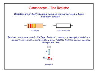
1. Components - The Resistor
Resistors are probably the most common component used in basic
electronic circuits.
Resistors are use to restrict the flow of electric current, for example a resistor is
placed in series with a light-emitting diode (LED) to limit the current passing
through the LED.
Circuit SymbolExample
VCC +
Gnd (0V)
R
LED
2. The Resistor Colour Code - 4 Band
The Resistor Colour
Code
Colour Number
0
1
2
3
4
5
6
7
8
9
±5%
±10%
Commonly used resistors have four colour bands to represent
the value of resistance. Three bands represent the value
and the forth band for the tolerance.
The first band gives the first digit of the value.
The second band gives the second digit of the value.
The third band indicates the number of zeros to be added to
the value.
This resistor has brown (1), red (2), orange (3) value bands.
Indicating that its nominal value is 12,000Ω or 12kΩ
The Ω sign is usually omitted on circuit diagrams and the
value is written as 12k.
The gold tolerance band indicates ± 5% about the nominal
value.
The actual value can lie between 11,400Ω and 12,600Ω.
3. The Resistor Colour Code
Activity
1. A resistor has colour bands yellow, violet, orange what is its value
(nominal).
2. A resistor has brown, black, red value bands and a gold tolerance
band. What is the nominal value and value range for this component.
3. You are asked to obtain a 68k resistor, explain how would you
recognise this.
4. A 36k and a 27k resistor are connected in series what would the be
the nominal value for this combination. If they both had gold tolerance
bands what would the be the upper and lower limits.
4. The Resistor Colour Code - 5 Band
The Resistor Colour
Code
Colour Number
0
1
2
3
4
5
6
7
8
9
As component manufacturing techniques became more
refined (use of laser trimming) and the use of high stability
materials (metal film) instead of carbon composition.
It became possible to manufacture much closer tolerance
components (0.5%, 1% and 2%) allowing the production of
more values in a range.
Three bands represent the digits of value and the forth band
the number of zeroes to be added. The fifth band is for the
tolerance.
What value is shown in the diagram?
5. Preferred Values
To produce a sensible range of resistor values you need to increase the size of
the 'step' as the value increases
Standard values form a series which follows the same pattern for every multiple
of ten these are known as preferred values.
E6 (20%)
6 values for each multiple of ten, 10, 15, 22, 33, 47, 68 and continues 100, 150, 220,
330, 470, 680, 1000 etc.
Notice how the step size increases as the value increases.
For this series the step to the next value is roughly half the value.
E12 (10%)
12 values for each multiple of ten, 10, 12, 15, 18, 22, 27, 33, 39, 47, 56, 68, 82 and
continues 100, 120, 150 etc.
(E6 series with an extra value in the gaps)
E24 (5%)
24 values for each multiple of ten, 10, 11, 12, 13, 15, 16, 18, 20, 22, 24, 27, 30, 33,
36, 39, 43, 47, 51, 56, 62, 68, 75, 82, 91 and continues 100, 110, 120, 130 etc.
(E12 series with an extra value in the gaps)
6. Film Resistors
Electrical energy is converted to heat when current is passed through a
resistor, however in most cases this energy is so small that the heat
produced can be ignored.
The amount of energy a resistor can safely convert to heat is dependant on its
power rating.
Where the energy is small the most common types of resistor is are the carbon
and metal film.
Film resistors have values ranging from tens of ohms to million of ohms.
Power rating for film resistors is from 0.125Watt to 1Watt.
7. Power Resistors
In some cases it is necessary to pass a high current through a resistance which
can result in heat being generated in the component.
We must ensure that the component continues to operate to specification and no
damage is caused as a result of this current.
The heat generated is also known as power dissipation.
Most power resistors are wirewound (not film) and very high power types are
encased in an aluminium cladding that acts as a heat sink or designed to be
mounted on a heat-sink to remove the heat from the component.
8. Variable Resistors (potentiometer)
Standard single
turn
Precision multi-turn
Rotary
potentiometers
Single turn
Preset
potentiometers
10 turn
precision
A potentiometer is a resistor that can have its value adjusted from zero to the
value stated on its case.
Standard potentiometers are used for amplifier controls by the equipment user and
can have either a rotary or slider wiper. Potentiometers used for volume
controls have a logarithmic scale.
Multi-turn rotary potentiometers used for precision instrumentation control
applications operated by the equipment user.
Preset potentiometers are mounted directly on the circuit board and used for
setting up and calibration by the manufacturer. Presets are not accessible to
the equipment operator.
9. Construction of a Potentiometer
Construction of a Carbon Track
Potentiometer and Circuit Symbol
Terminals
Control
shaft
Sliding
contact
(wiper)
Carbon
track
{
Variable resistors consist of a resistance track with a connection at either end and
a wiper that moves along the track as you rotate the spindle, see diagram.
The track can be made from carbon, cermet (matalised ceramic) or turns of
resistance wire.
θ rotation
0 330
Resistance
Lin
Log
Construction of a Carbon Track
Potentiometer and Circuit Symbol
10. Light Dependant Resistor (LDR)
Light dependant resistors use a semiconductor material whose resistance varies
according to the amount of light falling on it. Light provides energy to set free
electrons in the semiconductor material (cadmium sulphide) thus increasing
conductivity, (reducing its resistance).
ORP12 Symbol Response
light
Resistance
A common device is the ORP12 its resistance can range from 10MΩ in darkness to
500Ω in full light. LDR’s are used
11. Application of a Potentiometer
The potentiometer is commonly used in amplifiers as a volume control.
This control ‘sits’ between the pre-amplifier and the power amplifier and is used to
limit the amount of signal fed to the power amplifier.
Pre-amp Power amp
Output to
Speaker
system
Input
signal
gnd (0v)