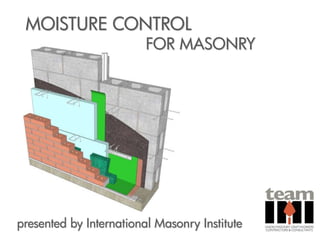
Moisture Control for Masonry
•
21 j'aime•5,854 vues

This program takes a detailed look at a masonry cavity wall’s moisture management system, analyzing the components of air space, flashing, weeps, air barrier, mortar joints, drainage accessories, the masonry materials themselves, and perhaps the most critical component to a watertight wall, workmanship procedures. It will look at details and conditions throughout the wall that present unique opportunities for moisture intrusion via bulk water, air infiltration, and vapor diffusion, and how to mitigate moisture at these conditions.

Recommandé
Contenu connexe
Tendances
Tendances (20)
En vedette
En vedette (17)
Similaire à Moisture Control for Masonry
Similaire à Moisture Control for Masonry (20)
Plus de Scott Conwell, FAIA, FCSI
Plus de Scott Conwell, FAIA, FCSI (10)
Dernier
Dernier (20)
Moisture Control for Masonry
- 1. MOISTURE CONTROL FOR MASONRY presented by International Masonry Institute
- 2. International Union International of Bricklayers and Masonry Allied Craftworkers Institute LIFELONG LEARNING Pre-job and apprentice training Journeyman upgrade training Safety, scaffold, OSHA training Craftworker certification training Supervisor certification Sustainable Masonry Certification Program Contractor College
- 3. BUILDING CODES IBC: the legally adopted model code MSJC: the referenced standard IBC supersedes MSJC at points of conflict MSJC date will be one year prior to companion IBC 2009 IBC goes with 2008 MSJC 2012 IBC goes with 2011 MSJC IBC & MSJC
- 4. 2012 INTERNATIONAL BUILDING CODE CHAPTER 21 - MASONRY SECTION 2101 GENERAL 2101.2.6 Masonry Veneer Masonry veneer shall comply with the provisions of Chapter 14 or Chapter 6 of TMS 402/ACI 530/ASCE 5. SECTION 2104 CONSTRUCTION 2104.1 Masonry Construction Masonry construction shall comply with the requirements of Sections 2104.1.1 through 2104.4 and with TMS 402/ACI 530/ASCE 5.
- 6. MOISTURE RESISTANCE Brick & mortar leak Wall system must address moisture penetration
- 7. 2011 MSJC 2011 Building Code Requirements for Masonry Structures (TMS 402/ACI 530/ASCE 5) CHAPTER 6 - VENEER 6.1 GENERAL 6.1.2 Design of Anchored Veneer e) Water will penetrate the veneer and the wall system should be designed, detailed, and constructed to prevent water penetration into the building. (commentary) 6.1.6 General Design Requirements Water penetration through the exterior veneer is expected. The wall system must be designed and constructed to prevent water from entering the building. (commentary)
- 9. MOISTURE RESISTANCE REQUIRED by Code Air space Flashing Weep holes Air Barrier* OPTIONAL Mortar Dropping Collection Device (MDCD) * depends on project location
- 12. MOISTURE RESISTANCE 2” recommended 1” min. for veneers, per code 4½” max. btwn. brick & backup AIR SPACE © 2009 INTERNATIONAL MASONRY INSTITUTE
- 13. MOISTURE RESISTANCE 2” recommended 1” min. for veneers per ACI 530 Code 4½” max. between brick and backup AIR SPACE © 2009 INTERNATIONAL MASONRY INSTITUTE
- 14. MOISTURE RESISTANCE No mortar bridging across the cavity! AIR SPACE © 2009 INTERNATIONAL MASONRY INSTITUTE
- 15. MOISTURE RESISTANCE 2” 2” AIR SPACE
- 17. MOISTURE RESISTANCE Bevel the bed joints CLEAN CAVITIES
- 18. MOISTURE RESISTANCE Mortar Dropping Collection Device (MDCD) CLEAN CAVITIES
- 19. MOISTURE RESISTANCE Mortar Dropping Collection Device (MDCD) CLEAN CAVITIES
- 20. CONCRETE MASONRY BACKUP AIR/WATER/VAPOR BARRIER AS REQ’D BRICK & BLOCK CAVITY WALL HORIZONTAL JOINT REINFORCEMENT W/ INTEGRAL WALL TIES 2” AIR SPACE RECOMMENDED; 1” MIN. REQ’D FOR DRAINAGE WALLS THRU-WALL FLASHING TO EXTEND PAST TOP OF CAVITY INSERT CAVITY INSERT/MORTAR COLLECTION DEVICE RIGID INSUL. BRICK VENEER WEEP VENT METAL DRIP EDGE SET IN MASTIC OR SEALANT International Masonry Institute MASONRY DETAILING FOUNDATION DETAIL SERIES DETAIL 01.102 REV. 10/14/07 800-IMI-0988 www.imiweb.org © 2007 INTERNATIONAL MASONRY INSTITUTE
- 21. MOISTURE RESISTANCE Full-height cavity insert CLEAN CAVITIES
- 22. MOISTURE RESISTANCE Cleanout openings CLEAN CAVITIES
- 24. AIR BARRIER: DEFINITION The International Energy Conservation Code defines an air barrier as: “material(s) assembled and joined together to provide a barrier to air leakage through the building envelope. An air barrier may be a single material or a combination of materials.” ABAA and IECC recognize air barriers in terms of: • materials • components • assemblies • systems
- 25. AIR BARRIER: DEFINITION A material, assembly, or system that restricts air leakage (flow)… L/s (cf/m) over an area of wall… m2 (sf) at a difference of air pressure Pa (psf) Source: ASTM E 2178, Standard Test Method for Air Permeance of Building Materials
- 26. IBC: WATER-RESISTIVE BARRIER 2012 International Building Code CHAPTER 14 – EXTERIOR WALLS Section 1403 Performance Requirements 1403.2 Weather protection Exterior walls shall provide the building with a weather-resistant exterior wall envelope. The envelope shall be designed and constructed in such a manner as to prevent the accumulation of water within the wall assembly by providing a water-resistive barrier behind the exterior veneer, as described in Section 1404.2. Protection against condensation in the exterior wall assembly shall be provided in accordance with Section 1405.3 Exception: A weather-resistant exterior wall envelope shall not be required over masonry walls designed in accordance with Chapter 21.
- 27. MSJC: WATER-RESISTANT MEMBRANE 2011 Building Code Requirements for Masonry Structures (TMS 402/ACI 530/ASCE 5) CHAPTER 6 - VENEER 6.1 GENERAL 6.1.6 General Design Requirements 6.1.6.1 Design and detail the backing system of exterior veneer to resist water penetration. Exterior sheathing shall be covered with a water-resistant membrane, unless the sheathing is water resistant and the joints are sealed.
- 28. IBC REFERENCES IECC 2012 International Building Code CHAPTER 13 – ENERGY EFFICIENCY Section 1301 GENERAL 1301.1.1 Criteria Buildings shall be designed and constructed in accordance with the International Energy Conservation Code.
- 29. AIR LEAKAGE 2012 International Energy Conservation Code CHAPTER 4 COMMERCIAL ENERGY EFFICIENCY SECTION C402 BUILDING ENVELOPE REQUIREMENTS C402.4 Air Leakage (Mandatory) The thermal envelope of buildings shall comply with Sections C402.4.1 through C402.4.8
- 30. AIR BARRIERS 2012 International Energy Conservation Code CHAPTER 4 COMMERCIAL ENERGY EFFICIENCY SECTION C402 BUILDING ENVELOPE REQUIREMENTS C402.4.1 Air Barriers A continuous air barrier shall be provided throughout the building thermal envelope. The air barriers shall be permitted to be located on the inside our outside of the building envelope, located within the assemblies composing the envelope, or any combination thereof. The air barrier shall comply with C402.4.1.1. and C402.4.1.2 Exception: Air barriers are not required in buildings located in Climate Zones 1, 2, and 3.
- 31. AIR BARRIER CONSTRUCTION 2012 International Energy Conservation Code C402.4.1.1 Air Barrier Construction 1. The air barrier shall be continuous for all assemblies that are the thermal envelope of the building, and across the joints and assemblies.* * Not required if building envelope passes ASTM E779 Standard Test Method for Determining Air Leakage Rate by Fan Pressurization. 2. Air barrier joints and seams shall be sealed, including sealing transitions in places and changes in materials. Air barrier penetrations shall be sealed in accordance with Section C402.4.2 The joints and seals shall be securely installed… as not to … impair its ability to resist positive and negative pressure from wind, stack effect, and mechanical ventilation.
- 32. AIR BARRIER COMPLIANCE OPTIONS 2012 International Energy Conservation Code C402.4.1.2 Air Barrier Compliance Options A continuous air barrier for the opaque building envelope shall comply with any one of the following: C402.4.1.2.1 Materials & Components or C402.4.1.2.2 Assemblies or C402.4.1.2.3 System
- 33. AIR BARRIER DEFINITIONS An AB material is a primary material used to resist air leakage. An AB component is a product like sealant or tape used to create continuity between air barrier materials. An AB assembly is a collection of AB materials and components assembled together in a specific manner to create continuity. An AB system is a system of building assemblies within the building enclosure designed, installed, and integrated in such a manner as to stop the uncontrolled flow of air into and out of the building enclosure. Source: Air Barrier Association of America (ABAA)
- 34. AIR BARRIER DEFINITIONS A material or component is an air barrier if it meets these maximum criteria: .02 L/s per m2 @ 75 Pa (.004 cfm/sf @ 1.56 psf) 1/2” sheet of gypsum board without seams, joints, or penetrations
- 35. AIR BARRIER DEFINITIONS A material or component is an air barrier if it meets these maximum criteria: .02 L/s per m2 @ 75 Pa (.004 cfm/sf @ 1.56 psf) An assembly is an air barrier if it meets these maximum criteria: 0.2 L/s per m2 @ 75 Pa (0.04 cfm/sf @ 1.56 psf) A system is an air barrier if it meets these maximum criteria: 2.0 L/s per m2 @ 75 Pa (0.4 cfm/sf @ 1.56 psf)
- 36. AIR BARRIER MATERIALS 2012 International Energy Conservation Code C402.4.1.2.1 Air Barrier Materials These materials meet the criteria of .02 L/s per m2 @ 75 Pa (.004 cfm/sf @ 1.56 psf) • 3/8” thick plywood • 3/8” thick OSB • 1/2” thick XPS insulation • 1/2” thick foil-backed polyisocyanurate insul. • 1½” thick, 1.5 pcf closed cell spray foam • 1/2” thick exterior or interior gyp bd. or cement bd. • 5/8” thick Portland cement/sand parge • 5/8” thick gypsum plaster • C.I.P. or precast concrete • Fully grouted CMU
- 37. AIR BARRIER ASSEMBLIES 2012 International Energy Conservation Code C402.4.1.2.2 Air Barrier Assemblies These assemblies meet the criteria of 0.2 L/s per m2 @ 75 Pa (.04 cfm/sf @ 1.56 psf) • Concrete masonry walls coated with one application of block filler and two applications of a paint or sealer coating. • A Portland cement/sand parge, stucco or plaster minimum 1/2” thick.
- 38. AIR BARRIER SYSTEM 2012 International Energy Conservation Code C402.4.1.2.3 Building Test Completed building (system) shall be tested and meet criteria of 2.0 L/s per m2 @ 75 Pa (0.4 cfm/sf @ 1.56 psf) ASTM E779 Standard Test Method for Determining Air Leakage Rate by Fan Pressurization
- 39. AIR BARRIER ATTRIBUTES • Impermeable • Continuous Coverage • Bridging Capability • Expected Service Life (Durability) • Secure • Environmentally & Worker Friendly
- 40. MOISTURE PENETRATION RESISTANCE Parged Mortar Sprayed Bituminous Spray polyurethane foam Rolled Bituminous Sheet membranes AIR BARRIER TYPES
- 41. MOISTURE PENETRATION RESISTANCE Prep wall by caulking any open joints Tool caulk joints AIR BARRIER © 2009 INTERNATIONAL MASONRY INSTITUTE
- 42. MOISTURE PENETRATION RESISTANCE Spray on first coat Roll membrane to required thickness AIR BARRIER © 2009 INTERNATIONAL MASONRY INSTITUTE
- 43. OPTION 1: AB, FLASHING OPTION 2: FLASHING, AB
- 44. AIR BARRIER PENETRATIONS & JOINTS 2012 International Energy Conservation Code C402.4.2 Air Barrier Penetrations Penetrations of the air barrier and paths of air leakage shall be caulked, gasketed, or otherwise sealed. Joints and seals shall be sealed in the same manner or taped or covered with a moisture permeable wrapping material. Joints and seals shall be securely installed in or on the joint for its entire length so as not to dislodge, loosen or otherwise impair its ability to resist positive and negative pressure from wind, stack effect and mechanical ventilation.
- 46. MOISTURE RESISTANCE Design and detail flashing and weep holes in exterior veneer wall systems to resist water penetration into the building interior. ACI 530-02/ASCE 5-02/TMS 402-02, Chapter 6 Veneer, Section 6.1.5.2 What type? What thickness? What locations? FLASHING – CODE REQUIREMENT
- 47. MOISTURE RESISTANCE “Approved, corrosion-resistant flashing” shall be provided in the exterior wall envelope in such a manner as to prevent entry of water into the wall cavity or penetration of water into the building structural framing components. ACI 530-02/ASCE 5-02/TMS 402-02, Chapter 6 Veneer, Section 6.1.5.2 FLASHING TYPES
- 50. MOISTURE RESISTANCE Plastic flashing should be at least 30 mil thick BIA Tech Note 28: Anchored Brick Veneer Wood Frame Construction FLASHING THICKNESS
- 51. MOISTURE RESISTANCE sills shelf angles top of wall base of wall above openings FLASHING APPLICATIONS
- 52. MOISTURE RESISTANCE Beneath the first course of masonry above finished ground level Other points of support such as shelf angles and lintels At top of all exterior window and door openings At intersection of chimneys Under sills At wall and roof intersections ACI 530-02/ASCE 5-02/TMS 402-02, Chapter 6 Veneers FLASHING LOCATIONS
- 54. MOISTURE RESISTANCE BASE OF WALL
- 55. FLASHING – BASE OF WALL
- 56. MOISTURE RESISTANCE Keep top of foundation above grade if possible Don’t bury the weeps! RISING DAMP
- 57. MOISTURE RESISTANCE best practice alternate FOUNDATION HEIGHT © 2009 INTERNATIONAL MASONRY INSTITUTE
- 58. 2” AIR SPACE RECOMMENDED; 1” MIN. REQ’D FOR DRAINAGE WALLS AIR/MOISTURE/VAPOR BARRIER AS REQUIRED HORIZONTAL JOINT REIN- FORCEMENT W/ EYE & PINTLE WALL TIES @ 16” O.C. RIGID INSULATION GROUT & REINFORCEMENT AS REQUIRED RETURN FLASHING INTO BED JOINT OF BLOCK CONCRETE MASONRY BACKUP BRICK VENEER FLEXIBLE FLASHING – SEAL & ADHERE TO DRIP EDGE WEEP VENT INSERTS (TOP & BOTTOM OF WALL; SEE NOTES ON COMPARTMENTALIZATION) DRIP EDGE – SEAL AND ADHERE TO FOUNDATION FOUNDATION DETAIL FLEX. FLASHING IN CMU, DRIP EDGE DETAIL 01.030.0305 REV. 07/01/09 © 2009 INTERNATIONAL MASONRY INSTITUTE
- 59. 2” AIR SPACE RECOMMENDED; 1” MIN. REQ’D FOR DRAINAGE WALLS AIR/MOISTURE/VAPOR BARRIER AS REQUIRED HORIZONTAL JOINT REIN- FORCEMENT W/ EYE & PINTLE WALL TIES @ 16” O.C. RIGID INSULATION GROUT & REINFORCEMENT AS REQUIRED MECH. FASTENED TERMINATION BAR W/ CONT. SEALANT @ TOP CONCRETE MASONRY BACKUP BRICK VENEER FLEXIBLE FLASHING – SEAL & ADHERE TO DRIP EDGE WEEP VENT INSERTS (TOP & BOTTOM OF WALL; SEE NOTES ON COMPARTMENTALIZATION) DRIP EDGE – SEAL AND ADHERE TO FOUNDATION FOUNDATION DETAIL FLEX. FLASHING, DRIP EDGE, TERM. BAR DETAIL 01.030.0301 REV. 07/01/09 © 2009 INTERNATIONAL MASONRY INSTITUTE
- 60. 2” AIR SPACE RECOMMENDED; 1” MIN. REQ’D FOR DRAINAGE WALLS AIR/MOISTURE/VAPOR BARRIER AS REQUIRED HORIZONTAL JOINT REIN- FORCEMENT W/ EYE & PINTLE WALL TIES @ 16” O.C. RIGID INSULATION GROUT & REINFORCEMENT AS REQUIRED MECH. FASTENED TERMINATION BAR W/ CONT. SEALANT @ TOP CONCRETE MASONRY BACKUP BRICK VENEER FLEXIBLE FLASHING – SEAL MORTAR DROPPING & ADHERE TO DRIP EDGE COLLECTION DEVICE (MDCD) WEEP VENT INSERTS (TOP & BOTTOM OF WALL; SEE NOTES ON COMPARTMENTALIZATION) DRIP EDGE – SEAL AND ADHERE TO FOUNDATION FOUNDATION DETAIL FLEX. FLASHING, DRIP EDGE, TERM. BAR, MDCD DETAIL 01.030.0302 REV. 07/01/09 © 2009 INTERNATIONAL MASONRY INSTITUTE
- 61. 2” AIR SPACE RECOMMENDED; 1” MIN. REQ’D FOR DRAINAGE WALLS AIR/MOISTURE/VAPOR BARRIER AS REQUIRED HORIZONTAL JOINT REIN- FORCEMENT W/ EYE & PINTLE WALL TIES @ 16” O.C. RIGID INSULATION GROUT & REINFORCEMENT AS REQUIRED MECH. FASTENED TERMINATION BAR W/ CONT. SEALANT @ TOP CONCRETE MASONRY BACKUP BRICK VENEER FLEXIBLE FLASHING FLUSH MORTAR DROPPING W/ OUTSIDE FACE OF BRICK COLLECTION DEVICE (MDCD) WEEP VENT INSERTS (TOP & BOTTOM OF WALL; SEE NOTES ON COMPARTMENTALIZATION) FOUNDATION DETAIL FLEX. FLASHING NO DRIP; TERM. BAR, MDCD DETAIL 01.030.0303 REV. 07/01/09 © 2009 INTERNATIONAL MASONRY INSTITUTE
- 62. 2” AIR SPACE RECOMMENDED; 1” MIN. REQ’D FOR DRAINAGE WALLS AIR/MOISTURE/VAPOR BARRIER AS REQUIRED HORIZONTAL JOINT REIN- FORCEMENT W/ EYE & PINTLE WALL TIES @ 16” O.C. RIGID INSULATION GROUT & REINFORCEMENT AS REQUIRED RETURN FLASHING INTO BED JOINT OF BLOCK CONCRETE MASONRY BACKUP BRICK VENEER FLEXIBLE FLASHING – SEAL MORTAR DROPPING & ADHERE TO DRIP EDGE COLLECTION DEVICE (MDCD) WEEP VENT INSERTS (TOP & BOTTOM OF WALL; SEE NOTES ON COMPARTMENTALIZATION) DRIP EDGE – SEAL AND ADHERE TO FOUNDATION FOUNDATION DETAIL FLEX. FLASHING IN CMU, DRIP EDGE DETAIL 01.030.0306 REV. 07/01/09 © 2009 INTERNATIONAL MASONRY INSTITUTE
- 63. 2” AIR SPACE RECOMMENDED; 1” MIN. REQ’D FOR DRAINAGE WALLS AIR/MOISTURE/VAPOR BARRIER AS REQUIRED HORIZONTAL JOINT REIN- FORCEMENT W/ EYE & PINTLE WALL TIES @ 16” O.C. RIGID INSULATION GROUT & REINFORCEMENT AS REQUIRED MECH. FASTENED TERMINATION BAR W/ CONT. SEALANT @ TOP BRICK VENEER CONCRETE MASONRY BACKUP MORTAR DROPPING COLLECTION DEVICE (MDCD) METAL FLASHING W/ INTEGRAL DRIP EDGE WEEP VENT INSERTS (TOP & BOTTOM OF WALL; SEE NOTES ON COMPARTMENTALIZATION) FOUNDATION DETAIL METAL FLASHING, TERM. BAR, MDCD DETAIL 01.030.0311 REV. 07/01/09 © 2009 INTERNATIONAL MASONRY INSTITUTE
- 65. FLASHING – SILL
- 66. SILL/JAMB DETAIL HIGH PERFORMING MASONRY WALL
- 67. WOOD BLOCKING FOR WINDOW ANCHORAGE ALTERNATE FLASHING LOCATION WINDOW STOOL NOT SHOWN WINDOW ASSEMBLY FLASHING RIGID FLASHING TO SPAN END DAM ACROSS DRAINAGE CAVITY RIGID INSULATION HORIZONTAL JOINT REINFORCEMENT MASONRY EXPANSION JOINT AS REQUIRED MASONRY SILL W/ 1/8” x 1/8” CONT. SAW-CUT DRIP SILL DETAIL MASONRY SILL, RIGID FLASHING DETAIL 01.030.0401 REV. 07/28/09 © 2009 INTERNATIONAL MASONRY INSTITUTE
- 68. MOISTURE RESISTANCE FLASHING - SILLS
- 69. MOISTURE RESISTANCE Best practice: Use limestone or precast sills Slope rowlocks at least 15º SILLS
- 71. FLASHING – HEAD
- 72. HEAD DETAIL HIGH PERFORMING MASONRY WALL
- 73. MOISTURE RESISTANCE Larger unit modules make end dams difficult FLASHING – END DAMS
- 74. BRICK & BLOCK CAVITY WALL DETAIL FEATURES EXTERIOR VIEW INTERIOR VIEW • LOOSE LINTEL AT BRICK • STEEL ANGLES AT BLOCK • LIGHT GAUGE SUPPORT International Masonry Institute ACROSS CAVITY MASONRY DETAILING HEAD DETAIL STEEL LINTEL W/ DOUBLE ANGLE SERIES DETAIL 01.303 REV. 09/06/07 800-IMI-0988 www.imiweb.org © 2007 INTERNATIONAL MASONRY INSTITUTE
- 75. BRICK & BLOCK CAVITY WALL INTERIOR VIEW DETAIL FEATURES • LOOSE LINTEL AT BRICK • BOND BEAM AT BLOCK International Masonry Institute • LIGHT GAUGE SUPPORT EXTERIOR VIEW ACROSS CAVITY MASONRY DETAILING HEAD DETAIL STEEL LINTEL & BOND BEAM SERIES DETAIL 01.301 REV. 09/04/07 800-IMI-0988 www.imiweb.org © 2007 INTERNATIONAL MASONRY INSTITUTE
- 76. SPANNING OPENINGS Poly-wrapped steel angles used for temporary support CAST-IN-PLACE MASONRY LINTEL
- 77. SPANNING OPENINGS Precast masonry lintel fabricated on the ground PRECAST LINTELS
- 78. SPANNING OPENINGS Lintel is hoisted by lift PRECAST LINTELS
- 79. SPANNING OPENINGS Precast lintel set into place PRECAST LINTELS
- 80. SPANNING OPENINGS 10-foot span PRECAST LINTELS
- 81. FLASHING – HEAD
- 83. 2” AIR SPACE RECOMMENDED; 1” HORIZONTAL JOINT MIN. REQ’D FOR BRICK & BLOCK CAVITY WALL REINFORCEMENT W/ DRAINAGE WALLS INTEGRAL WALL TIES RIGID INSUL. THRU-WALL FLASHING W/ METAL DRIP EDGE SET IN ADJUSTABLE MASTIC OR SEALANT SHELF ANGLE WEEP/VENT TYPICAL FACE ADJUSTABLE BRICK ABOVE & SHELF ANGLE BELOW ANGLE SEALANT & BACKER ROD International Masonry Institute COMPRESSIBLE FILLER, OPTIONAL MASONRY DETAILING SHELF ANGLE DETAIL TYP. FACE BRICK SERIES DETAIL 01.501 REV. 06/19/08 800-IMI-0988 www.imiweb.org © 2008 INTERNATIONAL MASONRY INSTITUTE
- 84. HORIZONTAL JOINT 2” AIR SPACE REINFORCEMENT W/ RECOMMENDED; 1” INTEGRAL WALL TIES MIN. REQ’D FOR DRAINAGE WALLS BRICK & BLOCK CAVITY WALL THRU-WALL FLASHING W/ METAL DRIP EDGE SET IN MASTIC OR SEALANT RIGID INSUL. WEEP/VENT ADJUSTABLE. SHELF ANGLE LIPPED BRICK, OPTIONAL SEALANT & BACKER ROD International Masonry Institute COMPRESSIBLE FILLER, OPTIONAL MASONRY DETAILING SHELF ANGLE DETAIL – LIPPED BRICK SERIES DETAIL 01.502 REV. 10/14/07 800-IMI-0988 www.imiweb.org © 2007 INTERNATIONAL MASONRY INSTITUTE
- 85. MOISTURE RESISTANCE Too many relieving angles FLASHING – RELIEVING ANGLES
- 87. FLASHING – ROOF/WALL CONNECTION
- 88. CMU BACKUP FACE BRICK CAVITY INSUL. THRU-WALL BRICK & BLOCK CAVITY WALL FLASHING ROOF MEMBRANE CUT BLOCK BELOW FLASHING COUNTER- FLASHING SHEET METAL RECEIVER THRU-WALL FLASHING WEEP VENT TERMINATION BAR W/ CONT. SEALANT ROOF STRUCTURE HORIZONTAL JOINT REINF. International Masonry Institute @ 16” O.C. W/ INTEGRAL WALL TIES MASONRY DETAILING ROOF DETAIL HIGH WALL – LOW ROOF SERIES DETAIL 01.704 REV. 11/6/07 800-IMI-0988 www.imiweb.org © 2007 INTERNATIONAL MASONRY INSTITUTE
- 89. MOISTURE RESISTANCE TOP OF WALL
- 90. FLASHING – TOP OF WALL
- 91. BRICK & BLOCK CAVITY WALL MASONRY COPING: LIMESTONE, CAST STONE, CALCIUM SILICATE, OR PRECAST CONCRETE; OVERHANG S.S. DOWEL W/ SEALANT MASONRY WALL 1½” MIN.; SLOPED AROUND PENETRATIONS TOP THROUGH FLASHING 1/8” SAW-CUT DRIP, BOTH SIDES OF WALL CAP SEE DETAIL 01.759 FOR WALL CAP JOINT OPTIONS SEALANT & BACKER ROD, BOTH SIDES THROUGH-WALL OF WALL CAP FLASHING W/ 1/2” DRIP EDGE GROUT OR MORTAR FILL FOR DOWEL ANCHORAGE AND FLASHING SUPPORT SEALANT BELOW DRIP, OPT. (NOT SHOWN) MESH TO RETAIN GROUT OR MORTAR FILL DRAINAGE CAVITY GROUT & REINFORCING FACE BRICK AS REQ’D. HORIZONTAL JOINT RIGID INSULATION REINFORCEMENT W/ WALL TIES International Masonry Institute MASONRY DETAILING MASONRY WALL CAP FILLED CAVITY SERIES DETAIL 01.752 REV. 11/04/08 800-IMI-0988 www.imiweb.org © 2008 INTERNATIONAL MASONRY INSTITUTE
- 92. BRICK & BLOCK CAVITY WALL MASONRY COPING: LIMESTONE, CAST STONE, CALCIUM SILICATE, OR S.S. DOWEL W/ SEALANT PRECAST CONCRETE; OVERHANG AROUND PENETRATIONS MASONRY WALL 1½” MIN.; SLOPED THROUGH FLASHING TOP 1/8” SAW-CUT DRIP, BOTH SIDES OF WALL CAP SEE DETAIL 01.759 FOR WALL CAP JOINT OPTIONS SEALANT & BACKER ROD, BOTH SIDES CANTED S.S. THRU-WALL OF WALL CAP FLASHING W/ 1/2” EXPOSED DRIP EDGE FACE BRICK SLOPED MORTAR BED TO SUPPORT CANTED FLASHING, SEALANT BELOW DRIP, OPT. OPT. (NOT SHOWN) RIGID INSULATION OPEN DRAINAGE CAVITY, OPTIONAL ABOVE ROOF LINE; ALSO SEE DETAIL GROUT & REINFORCING 01.752 AS REQ’D. HORIZONTAL JOINT REINFORCEMENT W/ WALL TIES International Masonry Institute MASONRY DETAILING MASONRY WALL CAP OPEN CAVITY SERIES DETAIL 01.751 REV. 11/04/08 800-IMI-0988 www.imiweb.org © 2008 INTERNATIONAL MASONRY INSTITUTE
- 93. MOISTURE RESISTANCE Drill through flashing for anchor Seal around dowel penetration TOP OF WALL
- 94. SINGLE WYTHE BLOCK MASONRY COPING: LIMESTONE, CAST STONE, CALCIUM SILICATE, OR PRECAST CONCRETE; OVERHANG MASONRY WALL 1½” MIN.; SLOPED TOP SEE DETAIL 01.759 FOR S.S. DOWEL W/ SEALANT WALL CAP JOINT OPTIONS AROUND PENETRATIONS THROUGH FLASHING S.S. FLASHING DRIP, SEALANT & BACKER BOTH SIDES OF CAP ROD, BOTH SIDES OF WALL CAP 1/8” SAW-CUT DRIP, BOTH SIDES OF WALL CAP GROUT OR MORTAR FILL FOR DOWEL ANCHORAGE AND FLASHING SUPPORT SEALANT BELOW DRIP, OPT. (NOT SHOWN) MESH TO RETAIN GROUT OR MORTAR FILL HORIZONTAL JOINT REINFORCEMENT International Masonry Institute MASONRY DETAILING MASONRY WALL CAP SINGLE WYTHE CMU SERIES DETAIL 03.701 REV. 11/04/08 800-IMI-0988 www.imiweb.org © 2008 INTERNATIONAL MASONRY INSTITUTE
- 95. MOISTURE RESISTANCE FLASHING – TOP OF WALL
- 96. MOISTURE RESISTANCE Rowlock caps not Limestone, manufactured stone, or recommended precast concrete caps are better TOP OF WALL
- 97. BRICK & BLOCK CAVITY WALL OPTION 1 OPTION 2 TOOLED MORTAR JOINT RAKE BACK MORTAR AND APPLY SEALANT JOINT OPTION 3 SEALANT AND BACKER ROD Rowlock caps not International Masonry Institute recommended MASONRY DETAILING MASONRY COPING JOINTS SERIES DETAIL 01.759 REV. 11/04/08 800-IMI-0988 www.imiweb.org © 2008 INTERNATIONAL MASONRY INSTITUTE
- 98. MOISTURE RESISTANCE TOP OF WALL
- 99. MOISTURE RESISTANCE Damage is more severe below joints in coping Freeze-thaw damage Flashing is held back from face at top courses FLASHING – PROBLEMS TO AVOID
- 100. MOISTURE RESISTANCE LAPS AND DRIP EDGES
- 101. MOISTURE RESISTANCE How far should flashing extend? Too much! Not enough! FLASHING – DRIP EDGES
- 102. MOISTURE RESISTANCE Metal drip edge is best practice! “The flashing shall extend to the surface of the exterior wall finish, and shall be installed to prevent water from reentering the exterior wall envelope.” - IRC Section R703 Flashing FLASHING – DRIP EDGES
- 103. 3/4” MIN. OVERLAP, SEALED W/ MFR-APPROVED ADHESIVE 1/2” MIN. IF RUBBERIZED ASPHALT IS USED FOR FLEXIBLE FLASHING, TO PREVENT DROOL FLEXIBLE THRU-WALL FLASHING METAL DRIP EDGE W/ HEM, 30º OR 45º FROM HORIZONTAL, SEALED TO FOUNDATION W/ MFR.-APPROVED ADHESIVE 1/4” – 3/4” 1 5/8” MIN. METAL DRIP EDGE DETAIL 15.000.0201 REV. 05/18/09 © 2009 INTERNATIONAL MASONRY INSTITUTE
- 104. MOISTURE RESISTANCE Lap all seams …and adequately seal! FLASHING – PROBLEMS TO AVOID
- 105. PRIMER PER RETURN FLASHING INTO MANUF’R BLOCK COURSE (SHOWN) OR SECURE TO BACKUP W/ TERMINATION BAR SEAL FLASHING LAPS W/ MASTIC PER MANUF’R 6” LAP DRIP EDGE SET IN SEALANT SUBJECT OF DETAIL EXCLUDED FROM SUBJECT THROUGH-WALL FLASHING OVERLAPS (LAPS) FLASHING DRIP EDGE LAPS, TERM. BAR, FACE BRICK, AND SEALING RECOMMENDATIONS CAVITY INSULATION, AND OTHER WALL COMPONENTS FLASHING LAP DIAGRAM 15.410.4101 REV. 02/10/11 © 2009 INTERNATIONAL MASONRY INSTITUTE
- 106. OUTER FACE OF MASONRY THROUGH-WALL FLASHING LAPPED AND SEALED OUTER FACE OF MASONRY NOTCHED DRIP EDGE 3/4”± METAL DRIP W/ HEMMED EDGE SET IN MASTIC OR SEALANT NOTCH DRIP EDGE FOR BUTT JOINT, International Masonry Institute SEE INSET ABOVE masonry detailing DRIP EDGE DETAIL series DETAIL 03.01 REV. 02/13/07 1-800-IMI-0988 www.imiweb.org © 2007 INTERNATIONAL MASONRY INSTITUTE
- 107. MOISTURE RESISTANCE 6” LAP FLASHING – LAPS
- 108. MOISTURE RESISTANCE Seal laps FLASHING LAPS
- 110. MOISTURE RESISTANCE Keep top of foundation above grade Don’t bury the weeps! FLASHING – INSTALLATION
- 111. MOISTURE RESISTANCE Flashing must be intact! FLASHING – PROBLEMS TO AVOID
- 112. MOISTURE RESISTANCE Hold rubberized as- Don’t use membrane phalt back from face as a drip edge FLASHING – PROBLEMS TO AVOID
- 113. MOISTURE RESISTANCE not stable Avoid using PVC FLASHING – PROBLEMS TO AVOID
- 114. MOISTURE RESISTANCE Avoid sharp corners Use rounded corners FLASHING – PROBLEMS TO AVOID
- 115. MOISTURE RESISTANCE Flashing held back from face FLASHING – PROBLEMS TO AVOID
- 116. MOISTURE RESISTANCE CORNER BOOTS & END DAMS
- 117. MOISTURE RESISTANCE Flashing discontinuous Continuous flashing at corner FLASHING – CORNERS
- 118. OUTSIDE CORNER FLASHING PIECE VIEW OF FINISHED CONTINUOUS FLASHING INSTALLATION (DRIP EDGES NOT SHOWN) INSIDE CORNER FLASHING PIECE OVERLAP FLASHING NOTE: FLASHING DRIP EDGES NOT SHOWN FOR CLARITY FLASHING CORNERS DETAIL 15.000.0204 REV. 08/24/09 © 2009 INTERNATIONAL MASONRY INSTITUTE
- 119. NOTE: FLASHING DRIP EDGE NOT SHOWN FOR CLARITY FLASHING CORNERS DETAIL 15.000.0204.PH REV. 08/24/09 © 2009 INTERNATIONAL MASONRY INSTITUTE
- 120. MOISTURE RESISTANCE Field-applied corner boot FLASHING – CORNERS
- 121. MOISTURE RESISTANCE end dam required! FLASHING – END DAMS
- 122. NOTE: STRUCTURAL ELEMENTS MAY VARY, AND ARE SHOWN FOR ILLUSTRATION ONLY CAVITY INSULATION NOT SHOWN FOR CLARITY OF DETAIL CARRY FLASHING ½” MIN. BEYOND END OF LINTEL AND TURN UP TO FORM END DAM IN HEAD JOINT 2” RECOMMENDED; 1” MIN. SEALANT EXTEND FLASHING FLUSH OR BEYOND FACE OF MASONRY END DAM DIAGRAM FIELD-FORMED FLASHING END DAM DIAGRAM 01.410.0201 REV. 02/04/11 © 2009 INTERNATIONAL MASONRY INSTITUTE
- 123. NOTE: STRUCTURAL ELEMENTS MAY VARY, AND ARE SHOWN FOR ILLUSTRATION ONLY CAVITY INSULATION NOT SHOWN FOR CLARITY OF DETAIL CARRY FLASHING ½” MIN. BEYOND END OF LINTEL PREFABRICATED END DAM IN HEAD JOINT; SET IN MASTIC IF FLASHING IS NOT SELF-ADHERING. END DAM PLACED PRIOR TO THROUGH-WALL FLASHING 2” RECOMMENDED; 1” MIN. EXTEND FLASHING SEALANT FLUSH OR BEYOND FACE OF MASONRY END DAM DIAGRAM PREFABRICATED FLASHING END DAM DIAGRAM 01.410.0202 REV. 02/04/11 © 2009 INTERNATIONAL MASONRY INSTITUTE
- 124. MOISTURE RESISTANCE FLASHING – END DAMS
- 125. MOISTURE RESISTANCE FLASHING – END DAMS
- 126. MOISTURE RESISTANCE FLASHING – END DAMS
- 128. MOISTURE RESISTANCE Weep holes shall be at least 3/16” in diameter and spaced less than 33” on center. International Residential Code 2000, Section R703.7.6 Weep Holes ACI 530-02/ASCE 5-02/TMS 402-02, Chapter 6 Veneer, Section 6.1.5.2 Best practice: 16” o.c. max for rope wicks, 24” o.c. for open head joints or vents WEEP HOLES
- 129. MOISTURE RESISTANCE head joint fiber mesh vent plastic vent sleeve plastic sash cord tube cell vent WEEP HOLES - TYPES
- 130. MOISTURE RESISTANCE “Weep holes shall be at least 3/16” in diameter and spaced less than 33” on center” International Residential Code 2000, Section R703.7.6 Weep Holes ACI 530-02/ASCE 5-02/TMS 402-02, Chapter 6 Veneer, Section 6.1.5.2 Best practice: Don’t use rope wicks! Best practice: 16” o.c. max for rope wicks (if you must), 24” o.c. for open head joints or vents WEEP HOLES – SIZE & SPACING
- 131. Best practice: Don’t use rope wicks! RESIDENTIAL MASONRY WEEP HOLES Best practice: if you must use rope wicks, lay them continuously along bottom of cavity
- 132. MOISTURE RESISTANCE Best practice: Don’t use rope wicks! Best practice: if you must use rope wicks, lay them continuously along bottom of cavity WEEP HOLES – PLACEMENT
- 133. MOISTURE RESISTANCE Vulnerable to mortar blockage Do not ventilate WEEP HOLES – ROPE WICKS
- 134. MOISTURE RESISTANCE Vulnerable to mortar blockage Do not ventilate WEEP HOLES – TUBES
- 135. MOISTURE RESISTANCE Better moisture relieve & ventilation May attract insects May mistakenly be caulked WEEP HOLES – OPEN HEAD JOINTS
- 139. MOISTURE RESISTANCE RECESSED AND PROJECTING COURSES
- 141. BRICK & BLOCK CAVITY WALL MORTAR WASH International Masonry Institute MASONRY DETAILING ARCHITECTURAL EFFECT SERIES DETAIL 01.601 REV. 08/31/07 800-IMI-0988 www.imiweb.org
- 143. MOISTURE RESISTANCE FULL HEAD JOINTS
- 146. BENEFITS OF BUILDING WITH MASONRY Beauty Versatility of Design Contextual / Relatable Ease of Construction Structural Fire & Impact Resistant Durable / Low Maintenance Economical Sustainable Energy Efficient High Performance Acoustic Qualified Local Labor