2. 56 ILBA Log Buiding Standards
ILBA Log Building Standards - Section A
Preface
1. In these Standards the word “shall” means
mandatory, and the word “may” means dis-
cretionary.
2. The 2000 Log Building Standards are comprised
of both the Standards and the Commentary.
Section 1 FOUNDATIONS
Shall conform to applicable building codes and
accepted engineering practice.
Section 2 LOG WALLS
2.A. Log Specifications
2.A.1. The minimum diameter of wall logs shall be
20 centimeters (8 inches).
2.A.2. Green or dry logs may be used for con-
struction.
2.A.3. Logs shall have all bark removed, and shall
be of sound wood.
Table 2.A
2.A.4. Spiral Grain:
The following restrictions apply to the use of
green logs. (Refer to Table 2.A for definitions
of spiral grain categories):
a. Left-hand severe spiral logs shall be used
as wall logs only as cut-in-half sill logs.
However, left-hand severe spiral logs may be
used as a whole-sill log if all four of the condi-
tions listed below are met.
b. Left-hand moderate spiral logs shall be
used only in the lowest one-third (1/3) of the
vertical height of a wall. However, left-hand
moderate spiral logs may be used in the low-
est one-half (1/2) of the vertical height of a
wall if all four of the conditions listed below
are met.
c. Right-hand severe spiral logs shall be used
only in the lowest one-quarter (1/4) of the
vertical height of a wall. However, right-hand
severe spiral logs may be used in the lowest
one-third (1/3) of the vertical height of a wall
if all four of the conditions listed below are
met:
Conditions:
1) the log has two or more corner notches,
and
2) the log is not spliced, and
Section 1 FOUNDATIONS
Like all buildings the foundation of a log building must be of suf-
ficient design to support safely the loads imposed as deter-
mined from the character of the soil. In addition to the
loads imposed by gravity, the foundation is important in
connecting the building to the ground as it resists wind or
seismic forces and accelerations. Therefore the connection
between the building and the foundation must also be
capable of resisting the sliding, uplift and overturning asso-
ciated with local wind and seismic conditions.
Section 2 LOG WALLS
2.A. Log Specifications
2.A.1. Logs smaller than 20 centimeters (8 inches) in diameter
are unsuited to residential construction.
2.A.2. For the purposes of this Standard, “dry” means moisture
content equal to or less than 19%, and “green” means
moisture content greater than 19%. Dry and green logs
have different requirements for preventing sapstain, and
have different shrinkage and structural properties that
must be appropriately accounted for in design and con-
struction.
2.A.3. Leaving the bark on logs promotes insect attack and
makes scribe-fitting difficult. Eventually, the bark will fall
off by itself, though by that time the wood has usually
been degraded by fungus or insects, or both.
2.A.4. Spiral grain is the condition in which the alignment of
wood fibers is at an oblique angle to the long axis of the
log. Spiral grain is expressed as the slope of the direction
of fiber alignment to the length of the log—this slope is
shown in Figure 2.A.
To determine fiber alignment, examine the log for surface
checks caused by drying—surface checks are parallel to
fiber alignment. Another option is to use a sharply pointed
timber-scribe instrument designed for detecting spiral
grain.
To determine whether a log has left-hand or right-hand spi-
ral grain, place your right hand on the log, fingers pointing
down the length of the log. You can stand at either end of
the log. If the grain spirals around the trunk like a barber
pole in the direction your thumb is pointing, then the tree
has left-hand spiral grain. If the grain spirals in the direc-
tion your little finger is pointing, then the tree has right-
hand spiral grain.
Scientific studies have shown that left-hand spiral grain
logs undergo more severe distortions during drying than
right-hand spiral grain logs, and this is one reason why
greater restrictions are placed on the use of left-hand spiral
logs (Table 2.A). Also, left-hand spiral grain logs are con-
siderably weaker in bending and deflect more than
straight-grain or right-hand spiral grain logs, though this is
more critical in using logs as structural elements (joists,
rafters, and timber members for example), than as wall
logs.
STANDARDS COMMENTARY
RIGHT HAND LEFT HAND
STRAIGHT LESS THAN 1:20 LESS THAN 1:30
MODERATE 1:20 TO 1:10 1:30 TO 1:20
SEVERE GREATER THAN 1:10 GREATER THAN 1:20
3. 57ILBA Log Buiding Standards
ILBA Log Building Standards - Section A
3) no more than two-thirds (2/3) of the log’s
diameter is cut or removed at any opening,
and
4) if any portion of this log extends beyond a
notch in a wall, then the length of this exten-
sion is not more than 4'-0", measured from
the center of the closest notch to the end cut
of this log.
d. Right-hand moderate spiral grain logs may
be used as a wall log at any location in the
building, except shall not be used in the top
round of logs.
e. Straight grain logs may be used in any
location.
f. The top round of logs shall be straight grain
only; see also Section 2.I.4.
Figure 2.A
2.B. Log Walls
Shall be constructed of logs laid in horizontal
courses, scribe-fit one to another, with inter-
locking notches at the corners.
2.C. Sill Logs
2.C.1. Shall be not less than 20 centimeters (8
inches) in diameter.
2.C.2. Shall be flattened on their bottom side for
their entire bearing length to a width of not
less than 10.2 centimeters (4 inches).
2.C.3. Shall not be in direct contact with masonry.
2.C.4. Shall be set on a vapor, weather, and air
barrier.
2.C.5. Shall have a drip cut or flashing that directs
water away from the underside of the sill log.
2.C.6. Shall be anchored to resist applicable wind
and seismic loads.
2.C.7. Shall be a minimum of 30.5 centimeters (12
inches) above grade
2.D. Long Grooves
2.D.1. Logs in walls shall have a continuous
scribe-fit long groove along the length of each
log. A long groove is required wherever a log
wall separates unheated from heated space,
or heated space from the exterior of the
building.
Section 2.A.4 describes the ways builders can help hold spiral
logs in place in the walls. Logs that are more likely to twist
are used lower in the wall, where there is more weight on
them. For spiral types (a), (b), and (c) the standards can
be relaxed somewhat if you use four additional methods to
restrict twisting. A log that has at least two full notches is
more likely to stay put than a log with one notch (condi-
tion #1). A full notch is more stabilizing than a splice notch
(condition #2). A spiral log with a window sill cut-out is
more likely to behave like it is one piece if no more than
two-thirds of a log’s diameter is removed (condition #3).
And, when a wall log extends beyond a notch more than 4'
to a door or window opening, this portion of the log is
more likely to twist (condition #4).
These tables refer to green logs, slope of grain will
change as logs dry.
2.B. Log Walls
These Standards do not apply to walls constructed of vertical
logs, logs that are not fully scribe-fit to one another, Piece
en Piece, or to manufactured log home kits. For more on
notches see Section 4.
2.C. Sill Logs
Sill Logs are the bottom logs of the building, the first logs above
the foundation in each wall.
2.C.1. See also the log specifications in Section 2.A.
2.C.2. A continuous sawn flat provides bearing area and stability
for sill logs.
2.C.3. Untreated wood should not be in direct contact with
masonry because of the likelihood of decay.
2.C.4. Caulks, sealants and gaskets can provide vapor, air and
water barriers.
2.C.5. To avoid decay, it is important that rainwater be directed
away from under the sill logs.
2.C.6. The amount and kind of anchoring depends upon local
conditions and codes. In areas of extreme wind and seis-
mic load conditions, continuous through-bolting the full
height of the log wall to the foundation can be an effective
technique.
2.C.7. Sill logs can be prone to decay if they are too close to
grade and rainwater and soil splashes on them.
2.D. Long Grooves.
Also known as “lateral,” “lateral groove,” “cope,” “Swedish
cope,” and “long notch.” The long groove is a notch cut
into a log to fit two logs together along their length
between intersecting corner notches.
2.D.1. The long groove must be continuous between notches or
openings, such as for doors. Other styles of log construc-
tion do not have a long groove, or have a groove that is
not continuous—the gaps between logs are then filled with
a chinking material. Scribe-fit logwork, in contrast, has a
continuous long groove, and no chinking is required
because there are no gaps to fill. The interior edges of the
long groove are often sealed with a gasket material, and its
interior is commonly insulated.
STANDARDS COMMENTARY
4. 58 ILBA Log Buiding Standards
ILBA Log Building Standards - Section A
Figure 2.D
2.D.2. Long grooves shall be self-draining or shall
have gaskets, and in all cases shall restrict
water, air, and insect infiltration.
2.D.3. The minimum width of the long groove shall
be 6.3 centimeters (2.5 inches) and this mini-
mum width shall extend for no more than
30.5 centimeters (12 inches) in continuous
length. At all times, however, the long groove
shall conceal and protect through-bolts, pins,
dowels, kerfs, electrical holes, and the like,
and shall be wide enough to restrict weather
and insect infiltration.
2.D.4. The maximum width of the long groove
shall be three-eighths (3/8) of the log diame-
ter at each point along the log. In cases of
extremely irregular log contours the width
may be increased to one-half (1/2) of the log
diameter, but this increased allowance shall
extend for no more than 46 centimeters (18
inches) in continuous length.
2.D.5. The long groove may have the following
cross-sectional profiles: rectangular, shallow
cove, “W” shaped, or double-scribed.
2.D.6. The depth to which the groove is cut shall
be no more than one-quarter (1/4) the diam-
eter of the log (see also Section 2.J.2).
2.E. Log Extensions
2.E.1. The maximum length of log extensions shall
be based on weather protection criteria
described in Section 7.D.
2.E.2. The minimum length of log extensions shall
be 23 centimeters (9 inches) measured from
the edge of the notch to the end of the log
overhang. This standard applies to both interi-
or and exterior log extensions. Dovetail corner
notches are exempt from this requirement.
2.E.3. Exterior log extensions shall not have a
tight fit to the log extensions below. See
Figure 3.B.3
2.D.2. Some profiles are not self-draining, that is they could
trap water, and so promote decay. Such long grooves
shall have gaskets to restrict water from getting into the
groove. Being visibly tight is not sufficient to restrict air or
water infiltration.
2.D.3. Narrow long grooves are difficult to seal from the weath-
er. The groove must always be wide enough to restrict
weather infiltration into kerfs, electrical holes, and the
like.
2.D.4. Wide long grooves remove so much wood that the log is
unduly weakened and may check only on the bottom of
the log, which is not desired. (See also Section 2.J.)
2.D.5. There are many shapes, or cross-sectional profiles, for
long grooves. Figure 2.D. illustrates some of these.
Desired traits are: sharp and strong edges along the scribe
line; a reasonable minimum amount of wood removed
from the groove so that the groove touches the log below
only along its scribed edges with no internal “hang-ups;”
and a reasonable assurance that the log will check on its
top (that is, in the kerf) as it dries. (See Section 2.J for
more on kerfs.)
2.D.6. Deep long grooves are not necessary, and can weaken a
log. Note that at least one-half of the diameter of the log
must remain intact after both the kerf and long groove are
cut (Section 2.J.2).
2.E. Log Extensions
Also known as “flyways” or “log overhangs,” are the short
part of the log that extends past a notched corner.
2.E.1. Overly long log extensions can be prone to decay unless
adequately protected by roof overhangs or other means.
2.E.2. Overly short log extensions can be prone to having wood
split off, severely weakening the notch and the corner.
Interior log extensions are those that project inside a
building, and exterior log extensions extend towards the
outside of a building. The stability of a dovetail corner
does not depend upon log extensions, and is not suscepti-
ble to having wood split off, and so is exempt from any
minimum length requirement.
2.E.3. The end-grain of exterior log extensions can take on
moisture seasonally, shrinking or swelling more than the
rest of the log. If the long grooves of extensions fit tightly,
then during periods of high moisture the tight fit of the
long grooves along the rest of the log could be compro-
mised. This has, in fact, been observed—tight long
grooves in the log extensions and gaps in the grooves
everywhere else.
Since log extensions are not kerfed (Section 2.J.7),
it is probable that log extensions will check on their bot-
toms—from their long grooves towards the center of the
log. When logs check in this location, internal hang-ups
are common. To avoid this, the grooves of exterior log
extensions should have enough wood removed to avoid
hang-ups after checking and slumping. See Figure 3.B.3.
STANDARDS COMMENTARY
5. 59ILBA Log Buiding Standards
ILBA Log Building Standards - Section A
2.E.4. Where a log extension acts as a support for a structural
member this extension and the structurally supporting logs
below shall be exempt from the requirement in 2.E.3 (see
also Section 7.J).
2.F. Distance Between Corners
2.F.1. When using logs with a diameter less than 30.5 centimeters
(12 inches) the distance between intersecting log walls with
corner notches shall be no more than 7.3 meters (24 feet).
When using logs with a minimum diameter of 30.5 centime-
ters (12 inches) the distance between corner notches shall be
no more than 9.75 meters (32 feet). Log walls with spans in
excess of these distances shall have reinforcement such as
wood keys, dowels, smooth-shaft steel, through-bolts, lag
screws, steel bar, or log stub-walls. All such reinforcement
shall allow for settling (see Section 6).
2.F.2. Log walls with openings cut for doors, windows and pas-
sageways may require additional bracing. The loads on a log
wall, and the openings cut into a log wall, will affect its struc-
tural performance and may require structural analysis.
2.G. Joining Logs Lengthwise
2.G.1. Spliced logs shall be secured to each other with bolts or
other fasteners, and to adjoining courses of logs above and
below with steel pins, wooden dowels, lag bolts or through-
bolts in a manner that preserves the structural integrity of the
wall.
2.G.2. When more than half of the logs in a corner are spliced,
then engineering analysis shall be required.
2.G.3. The notch and long-groove shall at all times completely
hide a splice and its fasteners, and help protect splices
against weather and insect infiltration.
2.H. Header Logs
2.H.1. A header log shall have no more than half of its vertical
height removed at the location of openings, unless it is cov-
ered by at least one more log. In all cases, the header log
shall be adequate for structural requirements.
2.E.4 Where roof overhangs, outriggers, or
balconies are supported by log exten-
sions, it may be necessary to have two,
or even three, log extensions fit tightly
so as to gain the structural strength
needed to support the cantilevered load
put on these logs.
2.F. Distance Between Corners
2.F.1. Log walls gain lateral stability from
corner notches at stub walls and inter-
secting log walls, and this is the reason
for limiting the distance between
notched corners. Larger logs are more
stable laterally than small logs and so
are allowed a longer maximum dis-
tance between notches.
2.F.2. Openings cut into a log wall, especial-
ly numerous, tall, or wide openings
reduce the lateral stability of the wall.
Some stability is gained by door and
window framing (see Section 5), but in
most cases other steps must be taken
to stabilize the wall, especially when
the wall is supporting the load of floors
or roofs.
2.G. Joining Logs Lengthwise
2.G.1. Some walls are too long to be
spanned with single logs, and so logs
are joined end-to-end. Better design
may be to step a long wall in or out to
add corner notches and allow the use
of wall-length logs, thereby eliminating
end-to-end splices. End-to-end butt
splicing of wall logs is an acceptable
practice, however, so long as steps are
taken to maintain the strength and sta-
bility of the walls and corners, and the
spliced joint is completely covered
from view.
2.G.3. The completed wall must appear to
be made of only continuous, full-length
logs. No exposed splices or joints are
allowed. All joints and splices must be
completely covered by corner notches
or stub-wall notches.
2.H. Header Logs
Header Logs are logs at the head, or top, of
window and door openings in log walls.
2.H.1. A header log has a level, sawn cut
facing the opening. These cuts should
not remove more than half the vertical
diameter of the header log at this point
unless the strength of the wall is suffi-
cient to support the roof and floor loads
placed upon it.
STANDARDS COMMENTARY
gasket
15°
3/4" nailer3/4" trim
(secure to 3/4" nailer only)
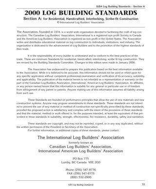
window frame head
window frame sill
Header Log
settling space
frame extension
if required
jamb trim
rabbet in 3/4" trim to allow
for settling of jamb trim
sealant
EXTERIOR INTERIOR
batt insulation
Sill Log
fastener
Figure 2.H
6. 60 ILBA Log Buiding Standards
ILBA Log Building Standards - Section A
2.H.2. Openings in header logs shall be cut
so as to completely cover door and
window head jambs and exterior trim in
order to restrict water infiltration.
2.I. Plate Logs
2.I.1. Wall plate logs shall be notched, drift-
ed, pegged, lag-bolted or through-bolt-
ed to the log below to prevent move-
ment caused by drying stress and roof
thrust. Wall plate logs shall be attached
with lag or through-bolts to one or
more rounds of logs below the plate log
so as to resist the uplift forces associat-
ed with local wind and seismic condi-
tions.
2.I.2. Where conventional framing meets a
plate log this intersection shall have an
expandable gasket to accommodate
anticipated shrinkage of the log plate
and to restrict weather and insect infil-
tration.
2.I.3. The ceiling vapor retarder, where
required by local code, shall be perma-
nently sealed to the plate log with caulk
or sealant.
2.I.4. Plate logs shall be straight grained
wood (see Section 2.A.4.f).
2.J. Kerfing
2.J.1. When building with green logs, a lon-
gitudinal kerf shall be cut on the top of
each wall log.
2.J.2. The depth of the kerf shall be at least
one-quarter (1/4) of the diameter of the
log, and shall be no deeper than one-
half (1/2) the diameter. In no case shall
more than one-half (1/2) the diameter
of the log be removed by the kerf and
long groove combined.
2.J.3. Kerfs shall at all times be protected
from weather by being fully covered by
the long groove of the log above, or by
a notch.
2.J.4. The kerf shall be continuous, or shall
start 15 centimeters (6 inches) from
the edge of all notches, and shall be
continuous between the notches,
except that kerfs need not extend into
openings in log walls, or at the ends of
log extensions, where they would be
seen.
2.H.2. Figure 2.H.1 illustrates one way to install settling boards and
avoid water infiltration.
2.I. Plate Logs
Plate Logs are the top logs on each wall. The roof framing rests on the
plate logs.
2.I.1. Wall plate logs are prone to twisting and shifting and need extra steps
to keep them in place. Square notches and lock notches can provide
restraint, as can any number of methods using bolts, threaded rod,
and pegs. The number, type, size and spacing of mechanical fasten-
ers used for this purpose must be determined by accepted engineer-
ing practice. Continuous gable end plate logs are very effective at
resisting roof thrust, and so are recommended when it is necessary
to counteract these forces. When continuous gable end plate logs are
not used, or are not used in a manner that will resist roof thrust, this
force must be restrained or eliminated by other methods.
Roof uplift caused by wind, for example, can be counteracted by
locking together the top rounds of each wall. Smooth pins such as
dowels, smooth shaft steel, and wooden pegs are not sufficient for
preventing uplift, and this is why lag bolts and through-bolts are
specifically mentioned.
2.I.2-3. A recent study of Minnesota log homes found the intersection of
roof framing and the plate log to be the source of considerable air
infiltration. Special steps are required to make this area weather-
tight. Permanently sealing the vapor barrier to the plate log is an
accepted method of reducing air infiltration and retarding the migra-
tion of water vapor. Stapling the vapor retarder to the plate log is, by
itself, not sufficient.
2.J. Kerfing
2.J.1. The kerf is usually, though not always, a cut made with a chainsaw.
Logs are known to check, or crack, in those places where wood has
been removed closest to the pith, (or the center) of the log. Kerfing is
therefore an effective way to control the location of checks as green
logs dry.
Because dry logs already have seasoning checks, kerfing usually will
not change the location of checks, and therefore kerfing is not
required for dry logs.
2.J.2. The kerf must be deep enough to promote checking. Note that even
those long groove profiles that do not require kerfing (like the dou-
ble-cut) are nevertheless required to be the depth of at least one-
quarter of the diameter of the log at every point along the top of the
log. (See also Section 2.D.5.)
After a log has both the kerf and the long groove cut, there must still
be at least one-half of the diameter of the log remaining un-cut.
Removing more than half the diameter of the log for kerf and groove
combined would weaken the log, and so should be avoided.
The amount of wood removed by the kerf (or special long groove
profile) must be between 1/4 and 1/2 of the log diameter (Section
2.D.6). When the kerf is 1/4 of the diameter of the log deep, then the
groove must be no more than 1/4 of the log diameter deep (1/4 plus
1/4 equals 1/2). When the kerf is 1/3 of the log diameter deep, then
the groove must be no more than 1/6 of the log diameter deep (1/6
plus 1/3 equals 1/2).
2.J.3. Because kerfs are not self-draining, that is, they can catch rainwater
and hold it, kerfs must always be protected by being fully covered by
the groove of the log above or by a notch (also see Section 2.D.3). In
practical terms, this means that kerfs are never visible in a complet-
ed wall.
STANDARDS COMMENTARY
7. 61ILBA Log Buiding Standards
ILBA Log Building Standards - Section A
2.J.5. No kerf shall be required when the long-groove profile encour-
ages checking on the top of wall logs as in Figure 2.D #2, as
long as the groove and kerf along the top of the log is at least
1/4 of the diameter of the log.
2.J.6. No kerf shall be required on the top of the half-log sill logs.
2.J.7. No kerf shall be cut in exterior log extensions.
2.K. Log Wall-Frame Wall Intersections
2.K.1. Log walls shall be cut as little as necessary when joined to
non-log partition walls.
2.K.2. Where wood is removed at the intersection of a log wall and
frame wall, the log wall shall have 55% or more of its cross-sec-
tional area remain intact and uncut. See Figure 2.K.2 below.
2.J.4. The kerf should run the full length of
the top of every log, either stopping
before reaching a notch or continuing
through a notch. In the case of open-
ings or passageways cut in log walls
that are not covered by jambs or
doors, the kerf would be unsightly—
and in these areas the kerf need not
extend all the way to the opening.
2.J.5. Some long-groove profiles encour-
age checking without kerfing. For
example, the long-groove known as
double-cut or double-scribed (see
Section 2.D.5), removes a “V”
shaped section from the top of every
log. Long-groove profiles that pro-
mote checking on top of wall logs do
not require a kerf, but they still must
comply with Section 2.J.2.
2.J.6. Half-logs do not usually check, and
so do not require a kerf.
2.J.7. No kerf should be cut on any log
extensions outside the building
because this upward-facing cut could
catch and hold moisture from rain
and promote decay. The long
grooves of exterior log extensions
shall not be tight-fitting (Section
2.E.3), and so do not protect the kerf
from water, and this is why log exten-
sions should not be kerfed.
2.K. Log Wall-Frame Wall
Intersections.
It is common for some interior, non-
bearing partition walls to be conven-
tionally framed with studs. This sec-
tion describes how stud walls and
other non-log walls should be
attached to logs walls.
2.K.1. It is common for a plumb groove,
dado, or rabbet to be cut in the log
wall and the first stud of the frame
wall to be attached to the log wall in
this groove. One problem is that to
have the frame wall completely seal
against the log wall, the groove must
be cut as deep as the narrowest long
groove, and this is often close to the
mid-point of the log wall. One way to
avoid removing too much wood from
the log wall, and unduly weakening
it, is shown in Figure 2.K.1, below.
2.K.2. Enough wood must be left in the log
wall that it is not weakened by the
dado. The dado must leave 55% or
more of the cross-sectional area at
this intersection uncut, Figure 2.K.1.
STANDARDS COMMENTARY
At least 55%
of log cross
section to
remain intact
at each notch.
frame wall
log wall
Plan View
FIGURE 2.K.1
CL
PLAN VIEW
SECTION VIEW
stud wall
let into a
log wall
55% or more of
cross section to
remain intact.
55% or more of
cross section to
remain intact.
stud wall
let into a
log wall
Figure 2.K.2
Plan View
8. 62 ILBA Log Buiding Standards
ILBA Log Building Standards - Section A
2.K.3. Where frame partition walls are notched
into opposite sides of a log wall there shall be
a minimum of 122 centimeters (4 feet)
between the end of one notch and the begin-
ning of the next notch on the opposite side of
the log wall, or, if closer than 122 centimeters
(4 feet), a minimum of one-third (1/3) of the
wall cross-sectional area shall remain intact
and uncut.
2.K.4. In no case shall cuts go past the centerline
or midpoint of the log wall.
2.K.5. Log wall-frame wall intersections must
allow for unrestricted settling of the log wall
(see also Section 6).
2.L. Height of Log Walls
Log walls taller than two stories, or 6.1 meters (20
feet) in height, shall require engineering analy-
sis.
2.M. Bearing Walls
Bearing walls shall be designed and constructed to
structurally accommodate horizontal and ver-
tical forces which are anticipated to act upon
the building.
2.N. Preservation of Log Walls
Where necessary, steps should be taken to restrict
the growth of mildew and fungus on logs
while the building is under construction.
Section 3 NOTCHES
3.A. Self-Draining and Weather-Restricting
Notching
All forms of interlocking notches and joinery
shall be self-draining and shall restrict weath-
er and insect infiltration. Shrink-fit and com-
pression-fit notches are recognized as achiev-
ing these goals.
3.B. Notching Standards
3.B.1. Notches shall have a concave profile across
the notch not less than 15 millimeters (9/16
of an inch) and not more than 35 millimeters
(1 and 3/8 inches).
2.K.3. Where two frame walls are closer than 122 centimeters (4
feet) to each other, and on opposite sides of a log wall, the
cross section of the log wall, after both dados are cut, must
have at least one-third of the wall area remain un-cut,
Figure 2.K.3 Note, also, that Section 2.K.1 still applies—
each single cut shall leave 55% or more of the cross sec-
tional area at each intersection un-cut and intact. See
Figure 2.K.3.
2.K.4. Cutting past the center of a log wall weakens it, and should
be avoided.
2.K.5. The first stud attached to the log wall must be fastened in
such a way as to allow the log wall to shrink and settle. One
common method is for lag screws to be attached to the logs
through vertical slots cut in the stud, not just round holes.
The lag screw and washer should be attached near the top
of the slot, and allowed to slide down the slot as the log wall
behind shrinks in height.
The frame wall must also allow a second floor, or the first
floor ceiling, to lose elevation as the log walls shrink in
height. (See Section 6 for more on settling.)
2.L. Tall log walls
Tall log walls should be evaluated for stability.
2.M. Bearing Walls
Bearing walls can be exterior or interior log walls. Roof and
floor loads are the most common loads to design for, but
uplift and lateral loads from winds and seismic activity may
have to be considered as well.
2.N. Preservation of Log Walls
Green logs, in particular, are prone to attack by mold,
mildew, and fungus during construction. Dry wood will not
decay, and so good roof protection is very effective in pro-
longing the life of log walls. During construction, and until
roof protection is complete, it may be advisable to use sap-
stain and mold preventative chemicals or processes.
Additionally the use of a sealant on all exposed end grain
during log storage, construction and after all work is com-
pleted will slow the loss of moisture and reduce checking.
Section 3 NOTCHES
3.A. Self-draining
Self-draining means that notch surfaces slope in a way that
restrict water from getting into areas where it can be held,
promoting decay. Interlocking means that notches will tend
to be stable when exposed to stresses and loads that the
corner can reasonably be anticipated to experience. Shrink-
fit and compression-fit notches are designed to remain tight
fitting as the wall logs shrink in size as they dry. (Note that a
round notch which is designed to function as a compres-
sion-fit notch also meets this criteria.)
3.B Notching Standards
3.B.1. When a straight-edge is held across a notch so that it is
approximately perpendicular to the long axis of the log and
so that the straight edge touches the scribed edges of the
notch, then the straight-edge should not touch the inside of
the notch at any place. In fact, the gap between the straight-
edge and the inside of the notch should be between 15 mil-
limeters and 35 millimeters.
STANDARDS COMMENTARY
4'- 0"less than 122 cm
(4 feet)
1/3 of log cross section to remain
intact and uncut between notches
At least 55% of log
cross section to remain
intact at each notch.
Plan View
Figure 2.K.3
9. 63ILBA Log Buiding Standards
ILBA Log Building Standards - Section A
3.B.2. Notches shall be clean in appearance and
have no ragged edges.
3.B.3. To maintain tight notches with green logs
the following apply:
a. Space shall be left at the top of the notch
to allow for compression.
b. Sapwood from the sides of the log should
be removed to create a saddle scarf. These
saddle scarfs shall be smoothly finished.
3.B.4. The amount of log to remain uncut at a
notch shall not be less than one-third (1/3)
the original diameter of the log, or not less
than one-third (1/3) of the original cross-
sectional area.
3.B.5. All forms of dovetail notches are exempt
from the requirements of Section 3.B.
3.C. Blind Notches
A blind-notch shall resist the separation of
the two log members it joins, or shall have
mechanical fasteners that resist separation.
Section 4 JOISTS AND BEAMS
4.A. Joists and beams, if dimensional material,
shall conform to applicable building codes.
4.B. Joists and beams, if log or timber, shall con-
form to the following standards:
4.B.1. Shall have straight grain, or shall be right-
hand spiral grain, with spiral no more than
1:12., and shall be of sound wood. (See
Section 2.A.4 for more on spiral grain.)
This means that the notch, when in place over the log below,
should touch the log below only on its scribed edges, and
should touch at no other place. (If it touches on some inside
place it causes a “hang up.” ) The concave area created by
scooping out the notch in this way not only prevents internal
hang-ups, but also can be used to place materials that will
prevent air infiltration through the notch (gaskets and insula-
tion, for example)—an important consideration in all cli-
mates.
3.B.2. The scribed edge of notches should be sharp, strong, and
cleanly cut. The edges should not crush or permanently
deform under the load they support. Ragged wood fibers
indicate weak notch edges or a notch cut past the scribe line.
3.B.3. There are techniques that help keep notches tight as green
logs season and dry. One technique is to remove wood at the
top of a notch to allow the notch to compress onto the log
below as it dries. The extra wood removed from the top of a
notch creates a gap that should be nearly invisible when the
corner is assembled, that is, the gap should be covered by
the notch of the next log. Figure 3.B.3.
Cutting saddles, or saddle scarfs, is another technique that
helps. Saddle scarfs should not be simply chainsawed off,
but should be finished to a smoother surface. See Figure
3.B.3.
3.B.4. After a notch has been cut there shall be no less than one
third of the log‘s original cross-sectional area or diameter at
the notch remaining uncut. Removing more than two-thirds
of the log area or diameter by notching weakens a log,
sometimes even to the point where the log extensions may
break off. Good log selection avoids the problem of notches
that remove more than two-thirds the diameter of the log at
the notch.
3.B.5. Dovetail notches are unlike most other notches, and are not
required to follow the standards of Section 3.B.
3.C. Blind Notches.
A blind notch is a log joint in which one log does not cross
over or beyond the other log. Because one log does not con-
tinue past or over, it can be prone to separating from the log
it is joined to. To resist separation the following methods are
recommended:
1. A dovetail or half-dovetail on the blind notch to interlock
with the intersecting log.
2. Hidden dowels that accommodate settling.
3. Hidden metal straps, fasteners or bolts to join the inter-
secting log walls together.
Section 4 JOISTS AND BEAMS
4.A. Dimensional joists and beams (including rafters, purlins,
ridges, and the like) shall conform to local applicable build-
ing codes, for dimensions, load, a and span.
4.B. Log joists and beams, including sawn timber members, shall
be sized to adequately support the loads they carry.
4.B.1. Studies have shown that left-hand spiral grain logs and tim-
bers are significantly weaker than straight and right-hand
grain members, but it is not yet known precisely how much
weaker. Therefore, left-hand grain is not allowed for these
members unless it can be shown that it is structurally ade-
quate. Straight-grain and right-hand spiral grain up to a
slope of 1:12 is allowed.
STANDARDS COMMENTARY
10. 64 ILBA Log Buiding Standards
ILBA Log Building Standards - Section A
4.B.2. Shall be designed to resist all loads according to applicable
building codes and accepted engineering practice.
4.C. Where log or timber beams are notched at an end, on the
bottom face, the depth of the notch shall not exceed one-
fourth (1/4) of the beam depth at the location of the notch,
or less, if calculations so indicate.
4.D. Where log or timber joists are supported by a log wall, the
wall logs shall be notched to receive the joists in such a way
as to prevent failure in the supporting log wall.
4.E. The distance, after settling is
complete, from the bottom of
ceiling joists and beams to the
finished floor shall conform to
applicable building codes.
4.F. Where a beam or joist passes
through a wall to support
additional floor areas or other
loads, the beam or joist shall be
notched in such a way that the
structural integrity of both the
beam and the supporting wall
are maintained.
4.B.2. At all times, log and timber beams and
joists must be designed and installed to
adequately resist the loads they will
experience. Joists and beams with
excessive deflection can cause uncom-
fortable, and in some cases, unsafe,
springiness in floors and roofs. Long
spans are prone to excessive deflection,
and in some cases a deflection limit of
1/360 of the span may not be sufficient.
It is prudent to consult with an engineer
familiar with wood structures for assis-
tance in the design of complex load car-
rying systems.
4.C. Where joists and beams are notched at
their ends (for example, to be supported
by a log wall), no more than one-quarter
(1/4) of the height of the beam shall be
removed from the bottom of the beam.
Less than one-quarter (1/4) shall be
removed if engineering calculations
require. See Figure 4.C.
4.D. It is also important to not remove so
much wood from a log wall that is sup-
porting a beam or joist such that the log
wall itself is unreasonably or unsafely
weakened. One example would be a joist
above a door or window opening, see
Figure 4.D.
4.E. Joists and beams (whether log, timber, or
dimensional material) that are supported
by log walls will get closer to the floor as
the logs dry and shrink and the log wall
gets shorter in elevation. Many local
building codes specify the minimum
height from the floor to joists and beams
above. The height of joists and beams
off the floor must conform to local build-
ing codes, if any, after settling is com-
plete. (See Section 6.A for more on cal-
culating settling allowances.)
4.F. One common log building design has
floor joists cantilever through an exterior
log wall to support a balcony or roof
load outside the building. It is not
uncommon for the stresses which this
type of beam must withstand to be at a
maximum where the beam passes
through the log wall. It is therefore
important that all such cantilevered
beams not be substantially weakened
due to notching at this location. A
square notch is one way to help protect
the strength of the beam, Figure 4.F.
Square notching does remove more
wood from the log wall than other notch-
es, and so it is important to ensure that
the wall is not weakened past its ability
to support the loads placed upon it.
STANDARDS COMMENTARY
A
B
C
Notch A: Too shallow, inadequate bearing,
edge of long groove could break out.
Notch B: Insufficient wood left
below notch.
Notch C: Adequate support.
Figure 4.C
Figure 4.D
Square notch
Figure 4.F
11. 65ILBA Log Buiding Standards
ILBA Log Building Standards - Section A
4.G. Where an interior beam extends through a wall to the exteri-
or it shall be protected from the weather so that its structur-
al integrity is maintained. The intersection of the beam and
wall shall be constructed to restrict weather and insect infil-
tration. See also Sections 7.F and 7.G.
4.H. Log joists and beams shall be flattened on top to a mini-
mum of 2.5 centimeters (1 inch) where they support floor-
ing or framing.
Section 5 WINDOW AND DOOR OPENINGS
5.A. Settling space shall be provided for all doors and windows
placed in walls constructed of horizontal logs.
5.B. The settling space for windows and doors shall be covered
by a cladding or trim to restrict weather and insect infiltra-
tion. In order to not restrict settling and to avoid damage to
windows or doors this covering shall not be attached to both
the log wall and to the window or door frame until after all
settling is completed. A vapor barrier shall be installed with-
in this space, on the heated side of the insulation.
5.C. Trim at jambs shall not restrict settling.
5.D. Both sides of each opening shall be keyed vertically to with-
stand lateral loads, and in such a way as to allow unrestrict-
ed settling.
5.E. All exterior sills shall be beveled to allow water to drain to
the outside face of the log wall.
4.G. Cantilevered log beams that extend out-
side the building (even if they are only
notched through the wall and have rela-
tively short log extensions) need protec-
tion against decay. Metal flashings,
waterproof membranes and wide roof
overhangs are recommended. The top of
any deck supported by logs or other
structural members must slope so that
water will drain in a manner that protects
the house from damage. This type of
detailing is important because of the sus-
ceptibility of unprotected log ends to
decay, and the great difficulty and
expense in repairing or replacing such
logs once degradation occurs.
Section 5 WINDOW AND DOOR
OPENINGS
5.A. Openings cut in log walls become shorter
over time as the logs dry to an in-service
condition. The settling space must not
have any materials in it that does not
allow for the space to become vertically
shorter over time. (See also Section 6 for
more about shrinkage and settling.)
5.B. Settling spaces are typically covered by
settling boards, which are pieces of trim
that are wide enough to span the settling
space. The settling boards can be
attached to the log or to the window or
door framing, but not to both. Attaching
the settling board to both would not
allow for the settling space to get smaller
over time, and would either cause the
logs to hang up, or the windows or doors
to deform.
5.C. The sides of doors and window trim must
allow for logs to settle un-hindered. This
means that the jamb trim on the sides of
doors and windows cannot be attached
to the log wall. Side trim can be attached
to the window or door and to bucks, see
Section 5. D. below.
5.D. Openings in log walls for door and win-
dows need The bucks are usually
attached to keys of wood or angle iron
that are let into the log ends of openings.
Keys are required because they hold the
bucks in place and because they lateral-
ly stabilize the log wall at openings: they
restrict logs from moving horizontally
while still allowing logs to move vertical-
ly. See Figure 5.D.1. and 5.D.2.
5.E. Where a log acts as an exposed exterior
window or door sill, it must shed water
and slope so that it drains away from the
window or door.
STANDARDS COMMENTARY
Log builder
rough opening
Carpenter
rough opening
window jamb
(provide pilot holes for
fasteners connecting
jamb to rough buck.
interior trim
shim space
rough buck with dado
cut to allow screw to
be mounted flush with
2x surface
wood screws
exterior trim
(secure to rough buck)
;;;;
;;
steel angle
in kerf
Carpenter
rough opening
interior trim
shim space
rough buck
2x key
in keyway
Log builder
rough opening
window jamb
(provide pilot holes for
fasteners connecting
jamb to rough buck.
exterior trim
(secure to rough buck)
Figure 5.D.1
Figure 5.D.2
12. 66 ILBA Log Buiding Standards
ILBA Log Building Standards - Section A
5.F. The position of openings in walls construct-
ed of horizontal logs shall conform to the
following:
5.F.1. The distance from the side of window and
door openings to the centerline of an inter-
secting log wall shall be a minimum of
25.4 centimeters (10 inches) plus one half
the average wall log diameter.
5.F.2. Wall sections between openings shall be
a minimum of 92 centimeters (36 inches)
long, or shall be provided with support in
addition to the required keyways (see
Section 5.D).
Section 6 SETTLING
6.A. Settling Allowance
6.A.1. The minimum allowance for settling
when using green logs is 6% (3/4 inch per
foot of log wall height).
6.A.2. The settling allowance for dry logs may
be up to 6%, but may be less than this,
depending upon the moisture content of
the logs.
5.F. Window and Door Location
5.F.1. It is undesirable to have door and window openings cut too
close to intersecting log wall and stub wall notches. The
notched log is weakened and may split off if it is too short.
(This situation is comparable to log extensions that are
required to be a certain minimum length, see Section 2.E.2.)
Therefore, window and door openings shall be cut no closer
to the centerline of an intersecting log wall or log stub wall
than 25.4 centimeters (10 inches) plus half the average wall
log diameter, see Figure 5.F.
5.F.2. Sections of log shorter than 92 centimeters (36 inches) are
prone to split, and are also unstable (since they do not con-
tain a log corner), especially if they support loads such as
those of a second floor or roof. Therefore, it is best if the sec-
tions of log wall between doors, between windows, and
between a door and a window, be longer than 92 centimeters
(36 inches). Sections of log wall can be shorter than this min-
imum if there is sufficient additional support used, but the
keys required by Section 5.D do not qualify as additional sup-
port, unless they are part of a column and screw jack settling
system.
Section 6 SETTLING
6.A. Settling is the term that describes the loss of log wall height
over time. The principal causes of settling are: 1) shrinkage of
log diameter as logs dry to an in-service condition (also
known as equilibrium moisture content, or EMC) and 2) com-
pression of wood fibers under the load of the building. A third
component is slumping, which occurs if logs check only in
the long groove. Slumping is nearly eliminated by kerfing,
which is one reason why kerfing is required, see Section 2.J.
6.A.1. Green logs (defined in Section 2.A.2 as logs with greater
than 19% moisture content) must be allowed to settle 6% (60
millimeters per meter, or 3/4 inch per foot) of wall height.
Note that logs cannot be expected to shrink to equilibrium
moisture content or completely settle by air-drying alone, but
must be expected to complete settling only after a period of
up to 5 years as part of a heated building. The time needed to
reach equilibrium moisture content depends on a number of
variables, including wood species, log diameter, initial mois-
ture content, interior temperature, and humidity and climate.
In general, logs do not shrink much in length, and so only the
loss of diameter must be considered for settling. With
extremely long logs (more than 15 meters (50 feet) long),
however, it is advisable to investigate the loss of length as
they dry.
6.A.2. Dry logs (defined in Section 2.A.2 as logs with moisture
content equal to, or less than, 19%) may settle nearly as
much as green logs. In part, this is because of the nature of
the definitions of dry and green—19% MC is a “dry” log and
20% MC is a “green” log, but these two logs will obviously dif-
fer very little in the amount they actually shrink in diameter
as they approach EMC.
It must be assumed that log walls made of dry logs will settle.
Further, it should be assumed that logs stored outside, not
covered by a roof, are not at EMC, and will shrink. The
amount of shrinkage depends upon the difference between
the actual moisture content of the logs (as determined by a
moisture meter, for example) and the final in-service EMC.
STANDARDS COMMENTARY
CL
25.4 cm (10")
+ 1/2 average
wall log diameter
window or
door opening
Figure 5.F
13. 67ILBA Log Buiding Standards
ILBA Log Building Standards - Section A
6.B. Adequate provisions shall be made for
settling at all openings, load bearing
posts, chimneys, fireplaces, interior frame
partition walls, electrical entrance boxes
and conduits, plumbing vents and drains,
second story water and gas pipes, stair-
cases, downspouts, heating and air condi-
tioning ducts, kitchen cabinets and all
other non-settling portions of the building.
6.C. The log contractor shall provide informa-
tion to the general contractor to help
guide sub-contractors in the use of tech-
niques applicable to their trade to deal
with the unique characteristics of log con-
struction, and specifically how each trade
should accommodate for settling.
6.D. All caulking and weather-sealing must
account for the change in diameter and
shape of the logs as they dry.
Section 7 ROOFS AND ROOF SUPPORT
SYSTEMS
7.A. If constructed of dimensional material,
roofs shall conform to applicable building
codes.
7.B. If constructed of log or timber, roof sys-
tems shall conform to the following stan-
dards:
7.B.1. Shall be constructed only of straight-
grain, or moderately right-hand spiral
grain material (see Section 2.A.4 for defi-
nitions of spiral grain).
7.B.2. Shall be designed to resist loads
according to applicable building codes
and accepted engineering practice.
7.B.3. Where beams are notched at an end, on
their bottom face, the depth of the notch
shall not exceed one-fourth (1/4) the
beam depth at the location of the notch,
or less if calculations so indicate.
7.C. The distance from the bottom of roof
beams to the finished floor must conform
to applicable building codes after settling
is complete.
7.D. Roof overhang shall help protect log walls
from the weather associated with the site
of the building. Figure 7.D illustrates how
to calculate the minimum roof overhang.
Settling allowance for dry logs may be reduced from the
required 6%, and the amount of the reduction allowed is pro-
portional to the moisture content of the logs. Note, however,
that even if the initial moisture content of the logs is equal to
EMC, and the logs are not expected to shrink, the logs will still
compress somewhat, and there must be a settling allowance
for this compression.
6.B. Everything that is attached to a log wall must accommodate
settling. Also, settling problems must be investigated even
between two non-log items. For example, there is settling to
accommodate between a second floor framed of 2x10’s and a
plumbing vent stack. Neither is log, but the floor framing is
attached to and supported by log walls and will settle. The
plumbing vent stack is anchored to non-settling members in
the basement or crawl space and does not settle.
Another example is the settling between a roof framed of
2x12’s and a chimney. Again, neither is made of logs, but
because the roof rafters are supported by log walls, this means
that the rafters will get closer to the ground as the log walls
settle. Therefore, roof framing must not be attached to a chim-
ney unless special steps are taken to accommodate settling.
The list in Section 6.B. is far from exhaustive. Every non-log,
non-settling, part of a building must be examined to see if
there needs to be an accommodation for settling.
6.C. The log builder knows the special techniques involved in com-
pleting a log house and should share this knowledge with the
general contractor so that the sub-contractors are properly
educated about settling and other potential problems.
6.D. Where caulks, sealants, gaskets, and the like are used in con-
tact with logs, these joints must be designed to accommodate
shrinkage of the logs without having the joint fail. Trim boards
that are scribe-fit to logs shall allow for settling.
Section 7 ROOFS AND ROOF SUPPORT SYSTEMS
7.B. Log roof systems include, but are not limited to, log posts and
purlins, ridgepoles, log trusses, and log common rafters. In
Section 7, “log” also means “timber.”
7.B.1. Severely spiral-grained logs are significantly weaker in bend-
ing strength and shall be avoided. Left-hand spiral grain logs
are significantly weaker than right-hand spiral grain of equal
angle. (See Section 2.A.4 for more on spiral grain.)
7.B.2. All log roof members shall be designed to sufficiently resist all
expected loads.
7.B.3-4. Notches cut into, and wood removed from a log beam will
weaken the beam. One example of this is at the ends of a sim-
ply-supported log beam, no more than one-quarter (1/4) of
the depth of the beam, and less if calculations so indicate,
shall be removed for a notch. (Figure 4.C.) It is best to consult
an engineer who is familiar with wood structures for help
designing log roof systems, and especially for complex roof
systems.
7.C. Consider the original height of the beam, the involved settling
height and the settling allowance (6% for green logs) to calcu-
late the height of roof beams after settling is complete.
7.D. Roofs for log homes shall protect log beams and log walls from
degradation caused by the weather. One good way to accom-
plish this is to use wide roof overhangs. The effectiveness of
roof overhangs also depends upon the height of the wall and
the height of the roof drip-edge. Figure 7.D shows how the
amount of roof overhang shall be calculated .
STANDARDS COMMENTARY
14. 68 ILBA Log Buiding Standards
ILBA Log Building Standards - Section A
7.E. The roof shall protect all roof structural members
from the weather associated with the site of the
building.
7.F. Log roof beams shall be flattened on top to a min-
imum width of 3.8 centimeters (1-1/2 inches)
where they support lumber or finish materials.
See Figure 7F.
7.G. Where log structural members pass through exte-
rior frame walls they shall be notched slightly to
receive interior and exterior wall coverings.
Expandable gaskets shall be installed to restrict
weather and insect infiltration. Roof members
shall be designed to meet structural requirements
even after such notching.
7.H. Flashing and an expandable gasket shall be used
where conventionally framed gable end walls
meet a plate log.
7.I. Roof structures shall be designed and constructed
to resist the uplift loads associated with local wind
and seismic events.
Notes for Figure 7.D.
The criteria set forth in Figure 7.D is a minimum.
This approach to calculating roof overhang is inde-
pendent of roof pitch and wall height, and relies on a
ratio (8:1) to define the relationship between the
roof overhang and the logs to be protected. If, for
example, the distance that the end of a sill log proj-
ects beyond the notch (Point A) is known, then the
drip line defined by the roof overhang can be calcu-
lated by projecting a line from Point A up and out
from the building at the 8 to 1 ratio as illustrated,
until this line intersects the bottom of the roof plane
(bottom of the rafters), then measure out horizontal-
ly here (Point B) to find the minimum roof overhang
distance.
Or, if the roof overhang is known, then the maxi-
mum projection of log ends beyond the notch can
be calculated by reversing the process and begin-
ning at Point B. A reference line is then constructed
down and inward toward the building at the 8 to 1
ratio until it intersects the plane of the bottom logs
(usually the first floor), then measure out horizontal-
ly to Point A to find the maximum allowed length of
log extensions. Also check that the log extensions
are not shorter than required in Section 2.E.2. Note
that the allowed length of log extensions increases
as you go higher on the building. That is, log exten-
sions may corbel out at the 8:1 ratio, if desired,
though they are not required to do so. At all points
around a building, this 8:1 reference line should be
used, and no log or log end should project beyond
this reference line.
7.E. Log roof beams that extend to the outside of a build-
ing need protection from the weather. Purlins, ridge-
poles, and posts must not extend outside the drip
line of the roof unless special steps are taken, for
example wrapping the log-end with a durable metal
flashing. Preservative chemicals by themselves are
insufficient.
7.F. It is impractical to attach framing lumber or finish
materials to the irregular, waney round of a log.
Therefore, round log roof beams shall be flattened to
a width of 1-1/2 inches or more where they support
other materials.
7.G. It is common to extend log roof beams, like purlins
and ridgepoles, outside over posts to support roof
overhangs. This can be a difficult spot to seal from
weather infiltration as the log roof beams shrink in
diameter. Gaskets help, as do shallow notches to
house the sheathing and inside finished wall materi-
als. Make sure that the roof beams are still suffi-
ciently strong even after notching and removing
wood.
7.H. The plate log of gable end log walls is flattened on
top, often to receive conventional stud framing. It is
important that the flat sawn on the plate log does
not hold or wick water. A metal flashing is an effec-
tive way to directly water away from this intersec-
tion.
6
drip line project
onto the ground
1
8
8
ridge
1
1
8
1
Point B
Point A
Drip Line
8
1
8
1
8
Shading represents
the area protected by the
6:1 gable end overhang.
All logs on the building
are to be protected by a
similar area created by
a sheltering overhang.
drip line projected
onto the ground
Figure 7.D
Figure 7.F
STANDARDS COMMENTARY
1 1/2"
15. 69ILBA Log Buiding Standards
ILBA Log Building Standards - Section A
STANDARDS COMMENTARY
7.J. Where roof structures are supported on outriggers,
which are in turn supported on log extensions, the
extension log carrying the outrigger shall be supported
by additional log extensions (a minimum of two exten-
sions below the extension carrying the outrigger) in
such a way as to support all loads from the outrigger
in a manner other than by cantilever action, unless the
log extension carrying the outrigger is designed and
constructed as a structural cantilever. (See also
Section 2.E.4.)
Section 8 ELECTRICAL
Shall comply with applicable codes, with accommodations
where necessary for pre-wiring and wall settling
allowance. (See also Section 6.B.)
Section 9 PLUMBING
9.A. Shall comply with applicable codes, with settling con-
siderations. See also Section 6.
9.B. A plumbing pipe shall travel through a log wall only
perpendicular to the long axis of the logs, and shall be
level or nearly level.
7.J. Log outriggers are roof plates outside of, and
parallel to, log eave walls. Do not use just one
log extension (log flyway) to support the outrig-
ger unless it can be shown that one extension is
sufficiently stiff and strong. In any case, no
matter how the outrigger is supported, its
means of support must be sufficient. (See
Section 2.E for more on log extensions.)
Section 8 ELECTRICAL
Common practice is to pre-drill vertical holes in
the log wall, from long groove to long groove,
so that the holes are completely hidden from
view and no electrical wiring is exposed inside
or out. (A diameter of 32 mm or 1-1/4” is often
used as a minimum.) Do not use conduit in a
log wall. Do not attach conduit to a log wall
without allowing for settling.
Outlets and switch boxes are usually mortised
into a log so that the cover plate is even with
the surface of the log, or, more commonly,
flush with a portion of the log that has been
flattened for this purpose, see Figure 8.
Section 9 PLUMBING
9.A. Investigate carefully the need for settling
allowances in all plumbing for log homes. It is
usually preferable to run plumbing in frame
walls vertically without horizontal offsets,
though offsets are possible, if settling consider-
ations are carefully made. Supply pipes to a
second floor can allow for settling by incorpo-
rating a loop that opens as the second floor
loses elevation. Waste and vent pipes can have
a slip joint. See Figure 9..A, 9.B, 9.C, 9.D.
9.B. It is usually not advisable to run plumbing
waste, vent or supply pipes through or within
log walls. If they must, however, pipes can run
perpendicular and level through a log wall. A
pipe that runs vertically up through a log wall,
or a pipe that runs horizontally within a log wall
(for example, lying in a long groove) can never
again be serviced without cutting the log wall
apart—a drastic event that is difficult to repair.
Because supply lines are known to age, fill with
scale and sometimes to leak and because the
venting of sewer gases is a matter of health and
safety it is best to not locate plumbing in log
walls.
wire
switch or
receptacle box
cover plate
hole drilled
through logs
A diameter of
32 mm (1-1/4")
is a suggested
as a minimum
cross-section of log wall
Figure 8
17. 71ILBA Log Buiding Standards
ILBA Log Building Standards - Section A
Section 10 FIREPLACES AND CHIMNEYS
10.A. Shall conform to applicable codes.
10.B. No combustible materials, including log walls, shall be
closer than 2 inches to a masonry chimney.
10.C. Flashing to conform to applicable codes, and to
accommodate settling (Figure 10). See also Section 6.
10.D. No portion of the building shall come into contact with
a masonry column unless the assembly is specifically
designed to accommodate structural and settling con-
siderations.
Section 10 FIREPLACES AND CHIMNEYS
10.C. The flashings used where a chimney goes
through the roof must accommodate settling
and protect against water and weather pene-
tration at all times, including after the build-
ing has fully settled. The roof, when support-
ed by log walls, will lose elevation while the
chimney will remain the same height. This
effect requires that chimneys be flashed and
counterflashed (see Figure 10). Further, the
flashing must be tall enough, and must have
sufficient overlap when the logs are green,
so that even after all settling is complete the
counterflashing still overlaps the flashing at
least 5.1 centimeters (2 inches), or more if
local building codes require or the situation
dictates.
Note: Because very tall areas of flashing can
be exposed (30 centimeters (12 inches)
high is not uncommon), it is recommended
that flashing material be thicker than normal
to protect the flashing from degradation.
Remember that the flashing and counter-
flashing cannot be attached to each other in
any way (solder, rivets, or etc.) because
they must freely slide vertically past each
other to allow settling.
10.D. This refers especially to a common practice
in stick-frame buildings—supporting roof or
floor beams on the masonry column of the
chimney. This must not be done in a log
home unless special measures are taken to
allow for settling.
It is desirable to position masonry columns
during the design process so that they avoid
areas in floors and roofs that require struc-
tural members. For example, position the
chimney so that it avoids the ridgepole and
purlins.
STANDARDS COMMENTARY
Side flashing stepped-up
in sections to align
with the roof 's pitch, or
install flashing in a kerf
cut into the masonry at
the roof's pitch.
Larger than
normal overlap
of flashing
over counter
flashing to
allow for
settling
A cricket flashing
is advised in this
location
DO NOT allow free
standing chimney to
contact log work
or roof system at anytime
unless allowances are
made for settling.
Figure 10
Inquiries, comments, suggestions, and additional
recommendations are welcome.
email: info@logassociation.org
Toll Free: 1-800-532-2900
ILBA, 2000c
18. 72 ILBA Log Buiding Standards
ILBA Log Building Standards - Section B
2.A.2. Green or dry logs may be used for con-
struction.
2.B. Log walls shall be constructed of logs laid in
horizontal courses with a chink gap between
logs and with interlocking notches at the
corners.
2.D. Chink Gap
2.D.1. Logs in walls shall have a continuous
chink gap along the length of each log
(except where interrupted by required struc-
tural blocking).
2.D.3. Minimum length of chink joint shall be 4”.
2.D.7. Blocking of not less than 3 1/2“ wide x 4”
deep in shall be installed in the chink gap.
Blocking height will vary. The blocking shall
be placed at each side of door or window
openings and at intervals determined by
local codes and conditions. Blocking shall
be installed so that flats are level in both
directions and centered on the chink gap.
Log walls with openings cut for doors, win-
dows and passageways require blocking at
each side of the opening to support log
ends. These opening may require structural
analysis.
2.D.8. Log wall pinning is necessary to resist
applicable wind and seismic loads.
2.D.9. Synthetic chinking material shall be
applied in chink gaps in such a manner as
to resist water, air and insect infiltration. At
all times, the chinking shall conceal and
protect through-bolts, pins, dowels, kerfs,
electrical holes, blocking, and the like. All
chinking shall be repaired upon visible evi-
dence of cracking or pulling away from logs.
Synthetic chinking shall be installed accord-
ing to joint designs that will favor “cohesive”
failure of the chinking (rather than “adhe-
sive” failure) if unavoidably extreme move-
ment should occur in a joint.
2.E.5. At load bearing extensions or where
blocking or pins are visible, chinking must
be applied.
2.G.3. The notch and chinking shall at all times
completely hide a splice and its fasteners
and help protect splices against weather and
insect infiltration.
STANDARDS COMMENTARY
Section B: 2000 LOG BUILDING CHINKING STANDARDS
2.A.2. Same as full scribe. For purposes of chinking appli-
cation, check with manufacturer as to proper moisture
content of logs at the time of chinking application.
2.B. See chink gap section 2.D. for more details.
Chink Gap
2.D. The chink gap is a continuous air space separating
logs between interlocking corners and/or window and
door openings; it should be interrupted only by
required structural blocking.
2.D.1. Chink gaps will be continuous without “holdups” at
any point along the length.
2.D.3. The width of chinking from inside face to outside face
will vary depending upon chink gap size and log diam-
eter. 8” is the minimum log diameter.
2.D.7. Blocking supports the log walls at the span and at
door and window openings. The flats, being level in
both directions and centered on the chink gap, prevent
blocking from rolling in the chink gap. An engineering
analysis is recommended to determine distance
between blocking. Additional blocking may be
required at load bearing points. If blocking supports
the log end at an opening, it must be installed so as
not to hinder settling, buck installation and chink
installation. The blocking should fall in a vertical col-
umn. In addition, pinning will provide stability
Examples of blocking:
1”x4” or 2”x4” kiln dried lumber, 4” long
3 1/2" x4” plywood 1/8” and thicker
3 1/2” x4”x1/8” masonite
30# felt
See diagrams 2.D.1. and 2.D.2.
2.D.8. The amount and kind of wall pinning depends upon
local conditions and codes. In areas of extreme wind
and seismic load conditions, continuous through bolt-
ing the full height of the logs can be an effective tech-
nique.
Examples of wall pinning:
Wood dowels, smooth shaft steel pins, through-bolts,
lag screws, steel bar or log stub walls.
2.D.9. Synthetic chinking should always be installed accord-
ing to manufacturer’s specifications. Moisture content
of the logs should be checked. Some manufacturers
recommend a 20% or less moisture content. For tradi-
tional or local chink mixtures, check local building or
energy codes to see if they are acceptable. Cohesion
failure of the chinking is preferred because it is easier,
faster and much less expensive to repair.
2.E.5. All extensions between heated and unheated space
shall be chinked to cover blocking and pins. Others
areas are optional.
2.F.1. Same as full scribe standards.
2.G.3. Same as full scribe standard.
19. 73ILBA Log Buiding Standards
ILBA Log Building Standards - Section B
2.H.1 A header log shall have no more than half of its
vertical height removed at the location of open-
ings, unless it is covered by at least one more full
log. In all cases, the header log must be support-
ed at each side by blocking and wall pinning and
be adequate for structural requirements.
2.l.2. Where conventional framing meets a plate log,
this intersection shall have chinking, elastomeric
caulking or an expandable gasket to accommo-
date anticipated shrinkage of the log plate and to
restrict weather and insect filtration.
2.J.2. The depth of the top kerf shall be at least one
quarter of the height of the log and shall be no
deeper than one half the diameter.
Section ll-Chinking (Synthetic)
ll.A.l. Before applying the chinking material, backer
rod shall be installed in the chink gap. The backer
rod shall fit snugly into the gap via either friction
or appropriate mechanical fasteners.
ll.A.2. Synthetic chinking material shall be applied to
the backer rod from notch to notch or notch to
door/window opening in such a manner that it is
self-draining and restricts air, water and insect
infiltration.
ll.A.3. Where appropriate internal gaskets are installed,
no chinking of notches and joints is required. All
other notches and joints shall be chinked.
ll.A.4. Chinking shall be applied with sufficient appli-
cation pressure and tooling to properly “wet out”
and establish strong adhesion to the contact sur-
faces of the logs. Such pressure and tooling can
eliminate regions where the chinking might other-
wise pull away and provide entry to moisture, air,
dust or insects.
ll.A.5. Where chinking is to be applied over structural
blocking, as much as possible, bond-breaking
materials such as, backer rod tape, etc., must be
applied between the blocking and the chinking to
avoid 3-point adhesion.
ll.A.6. The chinking shall be applied to surfaces that
are known to provide a suitable substrate for
strong chinking adhesion. Coatings containing
wax and oils that might lead to poor adhesion and
chinking failure are to be avoided.
ll.A.7. Fire-rated chinking systems shall be in careful
compliance with the manufacturer’s specifica-
tions.
STANDARDS COMMENTARY
2.H.1. Same as full scribe standard.
2.l.2. Same as full scribe standard.
2.J.2. The top kerf must be deep enough to promote
checking. The amount of wood removed by the
kerf should be between 1/4 and 1/2 of the log
depth.
Section ll-Chinking (Synthetic)
ll. Chinking is the material that goes between the logs
to fill the chink gap. It acts as a barrier against
air, insects, moisture and dust infiltration and
acts as a form of insulation.
ll.A.l. Backer rod comes in many forms. Each manu-
facturer has its preference as to style (flat or
round) and type (closed cell or open cell).
Using the manufacturer’s guidelines is recom-
mended. When changing size in backer rod due
to varying chink gap, do so gradually to allow
for a smooth transition in the chinking material.
(Note: Installing backer rod with adhesives,
spray or otherwise, can lead to poor adhesion
of chinking. Follow manufacturer’s guidelines.)
ll.A.2. Synthetic chinking shall be applied according
to manufacturer’s guidelines. It should have an
attractive, natural texture. The edges of the joint
should be clean and crisp where the chinking
meets the log. The backer rod should not show
through the chinking at any point. See figure
ll.A..
ll.A.3. When internal gaskets are used, air, water and
insect infiltration is restricted. Without gaskets,
the chinking material becomes the barrier to
infiltration.
ll.A.4. Wetout is the condition where too much of a
release agent (isopropyl alcohol combined with
50% water) is used to trowel the chinking mate-
rial. Excessive wetting may prevent the chink-
ing from properly adhering to the wood.