Collective Mining | Corporate Presentation - May 2024
Haifu ev iecon13tutorial
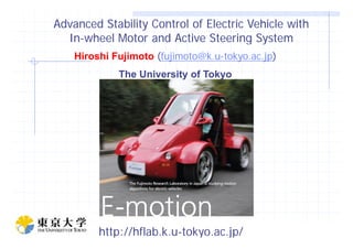
1. Advanced Stability Control of Electric Vehicle withAdvanced Stability Control of Electric Vehicle with
InIn--wheel Motor and Active Steering Systemwheel Motor and Active Steering SystemInIn wheel Motor and Active Steering Systemwheel Motor and Active Steering System
Hiroshi Fujimoto ((fujimoto@k.ufujimoto@k.u--tokyo.ac.jptokyo.ac.jp))
The University of Tokyo
Slide 1
H.FujimotoH.Fujimoto ((Univ.TokyoUniv.Tokyo))http://hflab.k.u-tokyo.ac.jp/
2. Hori/Fujimoto
Lab.
Dept. Advanced Energy Dept. Electrical Eng.
Frontier Sciences (Kashiwa) Grad. School of Eng. (Hongo)
Research Field: Control Engineering, Motion Control, Electric Vehicle,Research Field: Control Engineering, Motion Control, Electric Vehicle,
Wireless Power Transfer,Wireless Power Transfer, NanoNano--scale Servo, Power Electronics, Robotics,scale Servo, Power Electronics, Robotics,
Lab Members: 8 staffs (P, AP, Assistant P, 2 PDs, Engineer, 2 secretaries)
33 students (9 Ph.D, 19 M.S., 4 B.S., 1 R.S. , including 13 international
students)students)
EV Garage (250EV Garage (250㎡㎡))
ff ㎡㎡EV test field (2600EV test field (2600㎡㎡))
Slide 2
H.FujimotoH.Fujimoto ((Univ.TokyoUniv.Tokyo))
Kashiwa New CampusKashiwa New Campus
(40 min from center of Tokyo)(40 min from center of Tokyo)
3. Motion Control of EVs over ICVs
[Y.Hori, TIE ‘04]
Advantages of motors →High Control Perf.
f
■ Quick torque response N
i
f
Torque of Motors (1ms)
>> Torque of Engines (500ms)
S
i
B
>> Torque of Engines (500ms)
→ Anti-slip Controlp
■Measurable torque
→ Estimate of Road Cond.
■I di id l h l t l b IWM
Slide 3
H.FujimotoH.Fujimoto ((Univ.TokyoUniv.Tokyo))
■Individual wheel control by IWMs
→ Vehicle Stability Control in 2D
4. ContentsContents
1.1. IntroductionIntroduction
l d l f ll d l f l2.2. Development and Control of Original EV FPEV2Development and Control of Original EV FPEV2--KanonKanon
3.3. Vehicle Stability Control with Wheel Side Force SensorVehicle Stability Control with Wheel Side Force Sensor
4.4. Range Extension Control SystemRange Extension Control System
55 ConclusionConclusion5.5. ConclusionConclusion
Slide 4
H.FujimotoH.Fujimoto ((Univ.TokyoUniv.Tokyo))
5. In-wheel motors
Outer rotor type
Big torque generation
F t R
Direct drive system
No Transmission Loss of Gear
Hi h Effi i d S ll N i Front Rear
Maker Toyo Denki Seizo K.K., Ltd
Motor type Outer rotor type
High Efficiency and Small Noise
Quick response
Estimation by reaction force
Motor type Outer rotor type
Direct drive system
Rated torque 110[Nm] 137[Nm][ ] [ ]
Max torque 500[Nm] 340[Nm]
Rated power 6.0[kW] 4.3[kW]
Max power 20.0[kW] 10.7[kW]
Max speed 1113[rpm] 1500[rpm]
Slide 5
H.FujimotoH.Fujimoto ((Univ.TokyoUniv.Tokyo))
Motor mass 32[kg] 26[kg]
Cooling Natural air cooling
7. Active Front/RearActive Front/Rear
Stee ing S stemStee ing S stem
• 2 DC Motors (Maxon 250W) for Steering
Steering SystemSteering System •Front steering shaft is removable.
→Steer-by-wire
Slide 7
H.FujimotoH.Fujimoto ((Univ.TokyoUniv.Tokyo))
8. Development of Original EVDevelopment of Original EV
Slide 8
H.FujimotoH.Fujimoto ((Univ.TokyoUniv.Tokyo))
9. Principle of Driving Force EstimationPrinciple of Driving Force Estimation
m
Motion Equation of WheelMotion Equation of Wheel
r
m
d
Radius of wheelRadius of wheel
TJ
drFTJ
dt
d
dt
Inertia of wheelInertia of wheel
FFdd :Drive.Force:Drive.Force
Angular AccelAngular Accel
Motor torqueMotor torque
→→Measured byMeasured by
Inertia of wheelInertia of wheel
→→ConstantConstant
Angular Accel.Angular Accel.
→→Measured byMeasured by
SensorsSensors
CurrentCurrent
Driving Force FDriving Force Fdd can be estimated by this equation.can be estimated by this equation.
I t it i l l t d lti ith 0 1I t it i l l t d lti ith 0 1
Slide 9
H.FujimotoH.Fujimoto ((Univ.TokyoUniv.Tokyo))
In our system, it is calculated realtime with 0.1msIn our system, it is calculated realtime with 0.1ms
sampling.sampling.
10. AntiAnti--slip Controlslip Control
+ Wheel Speed
Dynamics of EV
+Accel. Signal
Wheel SpeedTorque Command
-
Swithc
Inverse Dynamics on Grip
+-gain
Slip Torque
Toque on adhesion
w.r.t wheel speed
ControllerController
Slide 10
H.FujimotoH.Fujimoto ((Univ.TokyoUniv.Tokyo))Without controlWithout control With controlWith control
11. Direct Yaw Control (DYC)Direct Yaw Control (DYC)
Slide 11
H.FujimotoH.Fujimoto ((Univ.TokyoUniv.Tokyo))
Yaw rate
12. DYC resultsDYC results
Without controlWithout controlWithout controlWithout control
Wi hWi h ll
Counter
steering
WithWith controlcontrol
g
Slide 12
H.FujimotoH.Fujimoto ((Univ.TokyoUniv.Tokyo))
With controlWith controlWithout controlWithout control
13. SlipSlip--ratio Control with Regenerative Brakingratio Control with Regenerative Braking
Mechanical Braking OnlyMechanical Braking Only Electric and Mechanical BrakingElectric and Mechanical Braking
Slide 13
H.FujimotoH.Fujimoto ((Univ.TokyoUniv.Tokyo))
14. Collaboration with Mitsubishi MotorsCollaboration with Mitsubishi Motors
Slide 14
H.FujimotoH.Fujimoto ((Univ.TokyoUniv.Tokyo))
15. ContentsContents
1.1. IntroductionIntroduction
l d l f ll d l f l2.2. Development and Control of Original EV FPEV2Development and Control of Original EV FPEV2--KanonKanon
3.3. Vehicle Stability Control with Wheel Side Force SensorVehicle Stability Control with Wheel Side Force Sensor
i.i. Lateral Force SensorLateral Force Sensor
iiii YawYaw rate Control by IWMs and Active Front/Rearrate Control by IWMs and Active Front/Rearii.ii. YawYaw--rate Control by IWMs and Active Front/Rearrate Control by IWMs and Active Front/Rear
SteeringSteering
44 R E i C l SR E i C l S4.4. Range Extension Control SystemRange Extension Control System
5.5. ConclusionConclusion
Slide 15
H.FujimotoH.Fujimoto ((Univ.TokyoUniv.Tokyo))
16. Research and Development of Yaw ControlResearch and Development of Yaw Control
ESC:Electronic Stability Control
S bili h hi l i b lli b 4 h l b kSystem to stabilize the vehicle motion by controlling yaw-rate by 4 wheel brake
independently. One of the active safety technologies. ESCs have already been
implemented in many commercialize cars.
A study of dynamics performance improvement by rear right and left
implemented in many commercialize cars.
independent drive system [Sugano (Mazda)]
Friction circle estimation and integrated control of 4 wheels independent dive
and 4WS [Ono (Toyota CRL)]
El t i C t l T S lit 4WDElectric Control Torque Split 4WD [Nissan]
Development of 4 wheel driving force control system [Mori (Honda)]
Integrated Vehicle Motion Control System“S-AWC” [Miura (Mitsubishi Motors)]
Motion Control of Electric Vehicle ith Tire Workload [I (B id t )]Motion Control of Electric Vehicle with Tire Workload [Iwano (Bridgestone)]
Effects of Model Response on Model Following Type of Combined Lateral Force
and Yaw Moment Control Performance for Active Vehicle Handling Safety
[O.Mokhiamar (Kanagawa U)]
Slide 16
H.FujimotoH.Fujimoto ((Univ.TokyoUniv.Tokyo))
[O o a a ( a aga a U)]
Mini-max Optimal Distribution of Lateral and Driving/Braking Forces
[Nishihara (Kyoto Univ)]
17. Wheel Lateral Force SensorWheel Lateral Force Sensor Slip Angle
• Lateral force detection by sensors in Hub-unit
• Possible to measure lateral force under suspension• Possible to measure lateral force under suspension
Velocity
Lateral Force
Normally
unknown
– Expected Big Contribution to Active Safety
– Intelligent wheels by these sensors and in-wheel
motors (and steer-by-wire)motors (and steer-by-wire)
• Recent development in Japan
– NSK : Sensing by wheel speed sensor and encorders
Slide 17
H.FujimotoH.Fujimoto ((Univ.TokyoUniv.Tokyo))
– NTN : Sensing by strain gauge
– J-Tekt
18. ContentsContents
1.1. IntroductionIntroduction
l d l f ll d l f l2.2. Development and Control of Original EV FPEV2Development and Control of Original EV FPEV2--KanonKanon
3.3. Vehicle Stability Control with Wheel Side Force SensorVehicle Stability Control with Wheel Side Force Sensor
i.i. Lateral Force SensorLateral Force Sensor
iiii YawYaw rate Control by IWMs and Active Front/Rearrate Control by IWMs and Active Front/Rearii.ii. YawYaw--rate Control by IWMs and Active Front/Rearrate Control by IWMs and Active Front/Rear
SteeringSteering
44 R E i C l SR E i C l S4.4. Range Extension Control SystemRange Extension Control System
5.5. ConclusionConclusion
Slide 18
H.FujimotoH.Fujimoto ((Univ.TokyoUniv.Tokyo))
19. Equation of Motion for 4 wheels independent drive/steering
・Longitudinal Motion Ü Ð Ü ÖÆ Æܼ
Ý Ð Ý Ö
・Lateral Motion
Æ Æ
Ð
ݼ
Ð
ÅÞ
・Yawing Motion
ÜÖÖ
ÜÖÐ
ÆÖ ÆÖÐÖ
ÅÞ
ÝÖÐ ÝÖÖ
)1( f Yawing Motion
Ö
(Driving/Braking Force Diff.)
)1,( rf
(Moment by Lateral Force)
Active steering or 4 wheel
・Sum of squares workload
minimization (Abe03)
Slide 19
H.FujimotoH.Fujimoto ((Univ.TokyoUniv.Tokyo))
independent vehicles have redundancy
in control input.
minimization (Abe03)
・Minimax (Nishihara06)
・Workload equalization (Ono07)
20. Load change in decelerating turning
Force saturation
Decrease of yaw-moment caused
by saturation destabilizes vehicleForce saturation
on rear left
y
motion.
Slide 20
H.FujimotoH.Fujimoto ((Univ.TokyoUniv.Tokyo))
21. Yaw-control of front/rear independent steering and rear IWMs
[Ando, Fujimoto, AMC10][Ando, Fujimoto, AMC10]
Ü Ð Ü ÖÆ Æܼ
Ý Ð Ý Ö
A x
FF 22 ÜÖÖÆÖ ÆÖÐ
Ð
ݼ
Ð
ÅÞ
z
yx
F
FF
η
22
Workload
ÜÖÖ
ÜÖÐ
Ö ÆÖ
Ö
ÐÖ
ÝÖÐ ÝÖÖ
FF Tyijxij
22
Objective function: sum of squares of workload
Ö
Friction circleFriction circle
ÜÞ
Æ
Wxx
F
J T
rljrfi zij
yijxij
,,,
2
O i l di ib i
Ý
Optimal distribution
Slide 21
H.FujimotoH.Fujimoto ((Univ.TokyoUniv.Tokyo))
Example of forceExample of force
saturationsaturation
22. Conventional (YMO): torque diff. only Optimal method: torque diff. and
front/rear steering/ g
Test by decelerating turning
Accelerates to 30km/h →step-type steering ( =0.06rad)fp yp g ( )
Decelerating turning with braking force -800N
C d i l t t t i di
Slide 22
H.FujimotoH.Fujimoto ((Univ.TokyoUniv.Tokyo))
Command signals: constant turning radius
fyf
l
V
a
l
V
2
*,*
23. Movie of Experimentsp
Torque diff and active F/R steerTorque difference only
Slide 23
H.FujimotoH.Fujimoto ((Univ.TokyoUniv.Tokyo))
Red: Force Vector Locus,Blue: wheel load,Blue dashed: Amplitude of force
24. Control input in experimentsControl input in experiments
Torque diff and active F/R steerTorque difference only
SteeringSteering
Torque
Command
Slide 24
H.FujimotoH.Fujimoto ((Univ.TokyoUniv.Tokyo))
25. Experimental results (yawExperimental results (yaw--rate, workload)rate, workload)
Torque diff and active F/R steerTorque difference only
Yaw
raterate
E li tiEqualization
of each wheel
workload
Workload
Slide 25
H.FujimotoH.Fujimoto ((Univ.TokyoUniv.Tokyo))
26. ContentsContents
1.1. IntroductionIntroduction
l d l f ll d l f l2.2. Development and Control of Original EV FPEV2Development and Control of Original EV FPEV2--KanonKanon
3.3. Vehicle Stability Control with Wheel Side Force SensorVehicle Stability Control with Wheel Side Force Sensor
4.4. Range Extension Control SystemRange Extension Control System
55 ConclusionConclusion5.5. ConclusionConclusion
Slide 26
H.FujimotoH.Fujimoto ((Univ.TokyoUniv.Tokyo))
27. Critical Problem of EVs
Critical issues for EVsCritical issues for EVs Mileage per chargeMileage per chargeCritical issues for EVsCritical issues for EVs Mileage per chargeMileage per charge
Comparison of ICV and electric vehicleComparison of ICV and electric vehicle
mileagemileage capacitycapacity cruising ragecruising rage
Gasoline vehicleGasoline vehicle ((ii) 21 km/L) 21 km/L ((gasoline 35Lgasoline 35L)) 735km735km
Electric vehicleElectric vehicle((ii--MiEVMiEV))88 km/kWhkm/kWh ((battery capacity 16 kWhbattery capacity 16 kWh)) 130km130km
[M.[M. KamachiKamachi, AVEC08], AVEC08]
EV’s cruising range is shorter than ICV’s range.EV’s cruising range is shorter than ICV’s range.
・・High efficiency motorHigh efficiency motor
・・Novel driving method by two reduction gearNovel driving method by two reduction gear
In order to solve this problemIn order to solve this problem・・・・・・
[K. Sakai, JIASC09][K. Sakai, JIASC09]
[A Sorniotti AVEC10][A Sorniotti AVEC10]
Slide 27
H.FujimotoH.Fujimoto ((Univ.TokyoUniv.Tokyo))
・・Novel driving method by two reduction gearNovel driving method by two reduction gear [A. Sorniotti, AVEC10][A. Sorniotti, AVEC10]
28. Range Extension Control System: RECSRange Extension Control System: RECS
Try to enhance the cruising range of EV’s by control technologiesTry to enhance the cruising range of EV’s by control technologies
(Assumption: EV has multiple motors)(Assumption: EV has multiple motors)
33 types of RECStypes of RECS developeddeveloped
••RECS I: Optimal torqueRECS I: Optimal torque distributiondistribution
••RECS II: Minimization the corneringRECS II: Minimization the cornering resistanceresistance
[Fujimoto,[Fujimoto, SumiyaSumiya IECON2011]IECON2011]
••RECS II: Minimization the corneringRECS II: Minimization the cornering resistanceresistance
••RECS III: Minimization motor outputRECS III: Minimization motor output [[EgamiEgami, Fujimoto, IECON2011], Fujimoto, IECON2011]
••Total optimization (RECS I + III) [Fujimoto,Total optimization (RECS I + III) [Fujimoto, EgamiEgami, IECON2012], IECON2012]p ( ) [ j ,p ( ) [ j , gg , ], ]
B ttB tt
RECS IIIRECS III
BatteryBattery
(+(+
Chopper)Chopper)
Inv.Inv. 11 MM11
……
……
V hi lV hi l
V
Inv.Inv. 44 MM44
……
……
VehicleVehicle
Slide 28
H.FujimotoH.Fujimoto ((Univ.TokyoUniv.Tokyo))
44 44
RECS IRECS I RECS IIRECS II
29. RECS I: Optimal torque distributionRECS I: Optimal torque distribution
Assumption: Front and rear independent motors Straight roadAssumption: Front and rear independent motors Straight roadAssumption: Front and rear independent motors. Straight roadAssumption: Front and rear independent motors. Straight road
The sum of the torque only needs toThe sum of the torque only needs to
satisfy the driver demands.satisfy the driver demands.
Torque distributionTorque distribution
Same accelerationSame acceleration
FrontFront RearRear
Slide 29
H.FujimotoH.Fujimoto ((Univ.TokyoUniv.Tokyo))
29Efficiency map of motor + inverterEfficiency map of motor + inverter
Optimize overall efficiency byOptimize overall efficiency by distibutiondistibution
30. Experiment of RECS IExperiment of RECS I
Experimental conditionsExperimental conditions
••Speed command:Speed command:
••Total torque command:Total torque command:
E l i hE l i h h i dh i d••Evaluation on theEvaluation on the chassis dynamometerchassis dynamometer
opt
Extended mileageExtended mileage
••1 kWh1 kWh 500 m500 m••1 kWh1 kWh 500 m500 m
••16kWh16kWh 8 km8 km
Slide 30
H.FujimotoH.Fujimoto ((Univ.TokyoUniv.Tokyo))
30
31. Collaboration with Mitsubishi Motors
Front MotorFront MotorFront MotorFront Motor
Rear MotorRear Motor
Prototype PHEV with 2 onPrototype PHEV with 2 on--board motorsboard motors
・・2 motors has different efficiency map.2 motors has different efficiency map.
・・2 differential gears for F/R wheels2 differential gears for F/R wheels
Proposed methodProposed method
1.0[kW]1.0[kW] reductionreduction
・・2 differential gears for F/R wheels2 differential gears for F/R wheels
・・Engine is stopped.Engine is stopped. Evaluate as Battery EVEvaluate as Battery EV
EV cruising range extensionEV cruising range extensionEV cruising range extensionEV cruising range extension
Cruising distance [km/kWh]Cruising distance [km/kWh] (at 50km/h constant speed)(at 50km/h constant speed)
Slide 31
H.FujimotoH.Fujimoto ((Univ.TokyoUniv.Tokyo))
1.52km extend per 1kWh1.52km extend per 1kWh
24.2km extend per 16kWh24.2km extend per 16kWh
32. RECSII: Cornering resistance minimization
RECS on curving road by left and right independent motorsRECS on curving road by left and right independent motors
c p
Mi i i f t t i lMi i i f t t i l bb N
c
Cornering resistanceCornering resistance
Minimize front steering angleMinimize front steering angle byby zN
Cornering resistanceCornering resistance
is reducedis reduced
<Conventional><Conventional> <Proposed><Proposed>
Cornering resistanceCornering resistance
Mileage per charge is extended!Mileage per charge is extended!
pc
Cornering resistanceCornering resistance
Driving forceDriving force
Slide 32
H.FujimotoH.Fujimoto ((Univ.TokyoUniv.Tokyo))
: yaw: yaw--moment generated by driving forcemoment generated by driving force
difference between left and right motorsdifference between left and right motors
zN
33. Cruse distance (km/kWh)Cruse distance (km/kWh)( / )( / )
<Conventional><Conventional> <Proposed><Proposed>
Slide 33
H.FujimotoH.Fujimoto ((Univ.TokyoUniv.Tokyo))
33
••V=15 [km/h]V=15 [km/h],,R=8 [m]R=8 [m]
Input power ofInput power of inveterinveter Front Steering AngleFront Steering Angle
34. Control Technologies of EV Developed inControl Technologies of EV Developed in Hori/FujimotoHori/Fujimoto Lab.Lab.
Advanced Safty
•Slip-ratio control
•Yaw-rage controlYaw rage control
•Slip-angle control
•…..
Driving Comfort
Pit hi t l
Range Extension
Control System
•Pitching control
•Roll control •Optimal Distribution
•Minimize Resistance
Slide 34
H.FujimotoH.Fujimoto ((Univ.TokyoUniv.Tokyo))
Minimize Resistance
35. ConclusionConclusion
1.1. SmallSmall--scale EV “FPEV2scale EV “FPEV2--Kanon” are designed and developedKanon” are designed and developed
with active front/rear steering and direct drive inwith active front/rear steering and direct drive in--wheelwheel
motors.motors.
2.2. Control theories developed with FPEV2Control theories developed with FPEV2--Kanon was applied toKanon was applied to
the prototype EVs ofthe prototype EVs of industiresindustires..the prototype EVs ofthe prototype EVs of industiresindustires..
3.3. Developed technologies are available not only Battery EVsDeveloped technologies are available not only Battery EVs
but also (Plugbut also (Plug--in) hybrid vehicles and FCEVs.in) hybrid vehicles and FCEVs.
Slide 35
H.FujimotoH.Fujimoto ((Univ.TokyoUniv.Tokyo))
36. New Developing EV (FPEV4 Sawyer)New Developing EV (FPEV4 Sawyer)
Main UnitMain Unit
LiLi--ionion BatteryBattery
L/R Individual OnL/R Individual On--board Motorboard Motor
(N of Turns:(N of Turns: 42T/21T)42T/21T)
InIn--wheel Motorwheel Motor
(N of Turns:(N of Turns: 12T/8T)12T/8T)
SubSub--unitunit
(N of Turns:(N of Turns: 42T/21T)42T/21T) (N of Turns:(N of Turns: 12T/8T)12T/8T)
Left/Right Individual OnLeft/Right Individual On--OnOn--board motor /board motor / InIn--wheel motorswheel motorsNonNon--driven Unitdriven Unit
Drive Unit in SubDrive Unit in Sub--unit which is installed both rear and frontunit which is installed both rear and front
>M fi ti i d ith f i i>M fi ti i d ith f i i
board Motorboard MotorDifferential GearDifferential Gear
=>Many configurations are examined with fair comparison=>Many configurations are examined with fair comparison
Provide common test platform (e.g. OnProvide common test platform (e.g. On--board motor +board motor +
Drive shaft vibrationDrive shaft vibration supressionsupression control = IWM?)control = IWM?)
Active Front and Rear Steering, Steer by wireActive Front and Rear Steering, Steer by wire
Slide 36
H.FujimotoH.Fujimoto ((Univ.TokyoUniv.Tokyo))
36
g, yg, y
Suspension geometry is tunableSuspension geometry is tunable
Lateral force sensorsLateral force sensors
Test driveTest drive@@EV test field in KashiwaEV test field in Kashiwa