SlideShare une entreprise Scribd logo
1  sur  100
Télécharger pour lire hors ligne
SEMANTIC WEB SERVICES FOR COMPUTATIONAL MECHANICS


                                        by


                             Thiti Vacharasintopchai


A dissertation proposal submitted in partial fulfillment of the requirements for the
                         degree of Doctor of Engineering


           Examination Commitee:       Dr. William Barry (Chairman)
                                       Prof. Worsak Kanok-Nukulchai
                                       Prof. Vilas Wuwongse
                                       Dr. Voratas Kachitvichyanukul


                        Nationality:   Thai
                  Previous Degrees:    B. Eng. (Civil Engineering)
                                       Chulalongkorn University
                                       Bangkok, Thailand
                                       M. Eng. (Structural Engineering)
                                       Asian Institute of Technology
                                       Bangkok, Thailand

                Scholarship Donor:     Royal Thai Government Followship


                          Asian Institute of Technology
                          School of Civil Engineering
                                    Thailand
                                November 2003


                                         i
ii
TABLE OF CONTENTS

Chapter   Title                                                           Page

          Title Page                                                         i
          Table of Contents                                                iii
          List of Figures                                                   v
          List of Tables                                                   vii

  1       Introduction                                                       1
          1.1 Background                                                     1
          1.2 Problem Statement                                              4
          1.3 Objectives                                                     4
          1.4 Scope                                                          5
          1.5 Research Approach                                              5
          1.6 Contributions                                                  5

  2       FEM and the Need towards Distributed Computing                     7
          2.1 Formulation of the Finite Element Method                       7
          2.2 Parallel Computing and Applications in Computational
              Mechanics                                                     10
          2.3 Towards an Application of Distributed Computing Technique     10

  3       Distributed Computing                                             13
          3.1 Distributed Computing Concepts                                13
          3.2 Methods of Problem Decomposition                              13
              3.2.1 Data Distribution                                       13
              3.2.2 Algorithmic Distribution                                14
              3.2.3 Load Balancing                                          16
          3.3 Applications in Scientific Computing                           16
              3.3.1 SETI@home Project                                       17
              3.3.2 Grid Computing                                          18

  4       Web Services                                                      21
          4.1 The Web Services Architecture                                 21
          4.2 Applications of Web Services in Scientific Computing           23

  5       The Semantic Web                                                  25
          5.1 General                                                       25
          5.2 Resource Description Framework (RDF)                          28
              5.2.1 Introduction                                            28
              5.2.2 An RDF Statement                                        28
              5.2.3 Identification of Resources                              28
              5.2.4 The RDF Model                                           28
              5.2.5 Defining RDF Vocabularies                                29
          5.3 DAML+OIL                                                      31
          5.4 DAML-S: Semantic Markup for Web Services                      36
          5.5 Inferences – Making Use of Resources and Ontologies           38

  6       XML Declarative Description                                       41
          6.1 Declarative Description Theory                                41

                                   iii
6.1.1 Specialization Systems                          41
        6.1.2 Declarative Descriptions                        42
        6.1.3 Semantics of Declarative Descriptions           42
        6.1.4 Equivalent Transformations                      43
    6.2 XML Declarative Description                           44
        6.2.1 XML Elements and XML Expressions                44
        6.2.2 Formulation of XML Declarative Description      45
        6.2.3 XML Equivalent Transformation                   46
    6.3 Ontology Modeling and Inference with XDD              49

7   Methodology                                               55
    7.1 A Semantic Web Services Framework for Computational
        Mechanics                                             55
    7.2 An Overview of the Research Tasks                     58
    7.3 Infrastructure Design and Development                 58
        7.3.1 Construction of Domain Ontologies               58
        7.3.2 Construction of Ontology Mapping Facilities     59
        7.3.3 Construction of Service Enactment Facilities    62
    7.4 Application Web Services Development                  63
        7.4.1 Design of XML Schemas and Ontologies            65
        7.4.2 Construction of DAML-S Ontology Instances and
                WSDL Documents                                65
        7.4.3 Implementation and Deployment of Application
                Web Services                                  66
    7.5 Illustrative Applications of the Framework            66

    References                                                83

    Index                                                     91


                            iv
LIST OF FIGURES

Figure   Title                                                                 Page

 3.1     Problem Decomposition: Data Distribution                                14
 3.2     Problem Decomposition: Algorithmic Distribution                         15
 3.3     Problem Decomposition: Hybrid Distribution Method 1                     15
 3.4     Problem Decomposition: Hybrid Distribution Method 2                     16
 3.5     Model of the NASA X-38 Crew Return Vehicle (Barnard et al.,
         1999)                                                                   19
 3.6     Mach Contours for the X-38 Crew Return Vehicle (Barnard
         et al., 1999)                                                           19

 4.1     Conceptual Web Services Model (Basha et al., 2002)                      22
 4.2     Roles of SOAP, WSDL and UDDI in Web Services Architec-
         ture (Basha et al., 2002)                                               23

 5.1     Example of an HTML Document                                             26
 5.2     HTML Document in Figure 5.1 as Rendered on a Web Browser                26
 5.3     Example of an RDF Description                                           27
 5.4     A Simple RDF Statement (adapted from W3C, 2003b)                        29
 5.5     Several RDF Statements about Resources (adapted from W3C,
         2003b)                                                                  30
 5.6     A Vehicle Class Hierarchy (adapted from W3C, 2003b)                     31
 5.7     An RDF/XML Encoding that Corresponds to Figure 5.6 (W3C,
         2003b)                                                                  32
 5.8     An Instance of a Class Defined in Figures 5.6 and 5.7 (W3C, 2003b)       32
 5.9     Definition of Properties Corresponding to Classes in Figures 5.6
         and 5.7 (adapted from W3C, 2003b)                                       33
 5.10    An Instance of a Class using Properties Defined in Figure 5.9
         (W3C, 2003b)                                                            34
 5.11    An Example of daml:Restriction Construct                                36
 5.12    Upper Levels of DAML-S Ontology (DAML-S, 2003b)                         39
 5.13    Semantic Web Stack Diagram (W3C, 2002)                                  40
 5.14    Definition of XML Namespace                                              40

 6.1     Typical Structure and Syntax of an XET Program (Anutariya
         et al., 2002)                                                           48
 6.2     XDD Description Modeling the Ontology Definitions of Class
         Person (Suwanapong, 2001)                                               50
 6.3     XDD Description Modeling the Ontology Instances of Class
         Person (Suwanapong, 2001)                                               50
 6.4     XDD Description Modeling the Ontology Axiom daml:inverseOf
         (Suwanapong, 2001)                                                      51
 6.5     An XET Program Corresponding to the XDD Descriptions in
         Figures 6.2 to 6.4 (Part 1 of 2)                                        52
 6.6     An XET Program Corresponding to the XDD Descriptions in
         Figures 6.2 to 6.4 (Part 2 of 2)                                        53
 6.7     Information Derived from the XDD Descriptions in Figures 6.2 to 6.4
         (Suwanapong, 2001)                                                      54

                                    v
7.1    An Overview of the Proposed Semantic Web Services for Com-
       putational Mechanics Framework                                       67
7.2    The Multi-tier System Architecture adopted in the SWSCM
       Framework (adapted from Cyran, 2002)                                 68
7.3    Example of a Material Ontology                                       69
7.4    The DAML-S Ontology                                                  70
7.5    A Service Profile Hierarchy for Computational Mechanics Ap-
       plication Web Services                                               71
7.6    A Hierarchy of Matrices Involved in Computational Mechanics          71
7.7    DAML-S Ontology Instance Describing Science.net Matrix
       Inversion Service                                                    72
7.8    DAML-S Ontology Instance Describing NumMethods.org Ma-
       trix Inversion Service                                               72
7.9    DAML-S Ontology Instance Describing Optimize.com Matrix
       Inversion Service                                                    73
7.10   DAML-S Ontology Instance Describing NumericalRecipe.net
       Matrix Inversion Service                                             73
7.11   WSDL Description of a Matrix Inversion Web Service by Num-
       Methods.org (adapted from Sintopchai et al., 2003) (Part 1 of 2)     74
7.12   WSDL Description of a Matrix Inversion Web Service by Num-
       Methods.org (adapted from Sintopchai et al., 2003) (Part 2 of 2)     75
7.13   Model of a Structure to be Analyzed by a Structural Analysis Agent   76
7.14   Example of an Input Data that Represents the Model in Fig-
       ure 7.13 (Part 1 of 2)                                               77
7.15   Example of an Input Data that Represents the Model in Fig-
       ure 7.13 (Part 2 of 2)                                               78
7.16   DAML-S Ontology Instance Describing Finite Element Ser-
       vice by Structural Analysis Agent B                                  79
7.17   Preliminary Schedule for the Proposed Research Tasks                 80


                                 vi
LIST OF TABLES

Table   Title                                                                Page

 5.1    Comparison between RDF(S) and DAML+OIL (DAML, 2002)                    34

 6.1    Definition of the XML Expression Alphabet (Wuwongse et al.,
        2000)                                                                  45
 6.2    Definition of the Basic Specialization Mapping Operator νX
        (Wuwongse et al., 2000)                                                47

 7.1    Examples of Mathematical and Physical Ontologies Related
        to Key Operations in Computational Mechanics                           60
 7.2    Examples of Conceptual Ontologies Related to Key Opera-
        tions in Computational Mechanics                                       61
 7.3    Examples of Axioms Related to Key Operations in Computa-
        tional Mechanics                                                       61
 7.4    Summary of Matrix Inversion Service Profiles in Figures 7.7 to 7.10     63
 7.5    Preliminary List of Application Web Services to be Developed           64
 7.6    Expenditure Estimates for the Proposed Research                        81


                                 vii
viii
CHAPTER 1
                                     INTRODUCTION

1.1   Background
         In performing the analysis of structures using numerical methods, computers must
be closely guided by human users. For example, consider the case of finite element anal-
yses, at first we have to examine a real world problem and model it as a problem domain
and boundary conditions subjected to applied forces. We may have to consult many design
codes or experimental results to obtain the forces for the analysis. Next, we have to discretize
the problem domain, either manually or through the help of automatic meshing software be-
fore letting the computer compute and assemble the element stiffness matrices, apply the
boundary conditions and solve for nodal solutions. We also have to use our experience and
judgment to select the element types and the constitutive models for the material and problem
being considered, examine the accuracy of the analysis results and, if necessary, repeat the
entire process to obtain accurate results. Moreover, for large and complex analyses, running
an entire process may take hours or days and special visualization techniques such as ani-
mating graphics or virtual reality may be needed to effectively interpret the analysis results.
This situation may be more complicated in the case that there exist incompatibilities between
input and output data format of software components employed, and may be tedious, take a
lot of time, and lead to inaccurate analyses if performed by inexperienced users.
         Solutions are available to improve the performance and user-friendliness of structural
analysis software. One could be modifying or inventing a new formulation of the analysis
method. Another could be using computer technologies to improve computing performance
and the interaction between computers and users. One example of the former is the develop-
ment of meshless methods such as the element-free Galerkin method (EFGM) (Belytschko
et al., 1994) which is an analysis procedure that avoids the need for meshing by employing
a moving least-squares technique (Lancaster and Salkauskas, 1981) in approximating the
field quantities of interest. An example of the latter is the application of parallel computing
techniques into the finite element analysis procedure, cf. Adeli and Kamal (1993) and Ya-
gawa et al. (1991), so that complex analyses are performed in shorter time. Improvement
of user-friendliness in structural analysis software may come at the cost of an increase in
computational requirement, thus in some cases combination of the two solutions is also con-
sidered. For example, a parallel computing technique was employed to make analyses using
EFGM analyses more practical to users (Barry and Vacharasintopchai, 2001b).
         Distributed computing technologies, in particular, Web Services (W3C, 2003d) and
the Semantic Web (Berners-Lee et al., 2001), are available in computer science to help unify
and utilize the scattered resources, such as personal computers, clusters, supercomputers,
databases or knowledge-bases, and can be applied in structural engineering to make numer-
ical analysis of structures performed in a fast, accurate and more automated manner. With
Web Services and the Semantic Web, we wil not have to be actively involved in the analyses
by feeding the computers all the data and elaborate instructions, but instead be involved in a
less active way by giving simple instructions to the computers, watching them work for us,
and making a final decision on the results. With the advent of high-speed networks and the
maturity of researches in artificial intelligence, the Internet is not just a hyper-library for us
to search for information nor a communication tool for us to send emails or messages. We
could use the Internet as a very large platform for scientific computations with the help of
intelligent software agents that collaborate to accomplish a given task.
         Web Services and the Semantic Web, two technologies built on top of the Internet,

                                               1
are technologies that “will transform the web from a collection of information into a dis-
tributed computational device” (Fensel and Bussler, 2002). Web services are a new breed
of Web application that enables collaboration on the Web. They are self-contained, self-
describing, modular applications that can be published, located, and invoked across the Web.
Web services perform functions, which can be anything from simple requests to complicated
processes. Once a Web service is deployed, other applications (and other Web services) can
discover and invoke the deployed service (Tidwell, 2000). The Semantic Web, on the other
hand, is a technology that enables computers accessing data on the Web to be intelligent. Up
to now, the World Wide Web has developed rapidly as a medium of documents for people
rather than of information that can be manipulated automatically by computers. By augment-
ing Web pages with data targeted at computers and by adding documents designed solely for
computers, the Web will be transformed into the Semantic Web where computers can find the
meaning of semantic data by following hyperlinks to definitions of key terms and rules for
reasoning about them logically (Berners-Lee et al., 2001). The combination of Web Services
and Semantic Web technologies, termed Semantic Web Services (McIlraith et al., 2001), will
enable automated discovery, execution, composition, and interoperation of web services to
accomplish any tasks requested by human users. Automation is not achieved by humans
hard-coding programs into software agents but rather by the agents themselves through rea-
soning processes that lead to understanding. Such reasoning and automated operation are
based on ontologies, which are the formal, explicit specifications of shared conceptualiza-
tions of the world (Broekstra et al., 2002) and, like web pages, can be individually published
and linked to other ontologies across the Internet.
        In terms of numerical analysis of structures, Semantic Web Services may be applied
to assist human users in the analysis and design of structures as in, but not limited to, the
following scenario:

   • At first one examines a real world problem, defines the problem domain for the analy-
     sis, and inputs the data as well as important analysis keywords into a structural analysis
     software agent, which is a web service that performs analysis of structures on behalf
     of human users or other agents. The keywords may be related to material types such
     as mild steel, aluminum, reinforced concrete or ASTM1 A36 steel, material charac-
     teristics such as linear elastic, elastoplastic, viscoelastic, or viscoplastic, modes of
     analysis such as static, dynamic, buckling, or fracture, or boundary conditions such as
     cantilever, simply-supported, three-edge fixed supported, building codes such as the
     Uniform Building Code (UBC) and the National Building Code (NBC), and design
     specifications such as the American Institute of Steel Construction (AISC) specifica-
     tions, the American Concrete Institute (ACI) specifications, and the British Standards
     (BS) specifications.

   • Next, the agent consults its ontology to understand the user’s request and construct a
     set of problem parameters to perform an analysis. For example, if the user instructs
     the agent to

           find the maximum service stresses of an ASTM A36 steel plate with dimen-
           sions of 1.00 m wide by 200 cm long with a quarter inch thickness simply
           supported on all edges and subjected to the residential floor live load spec-
           ified in the latest version of UBC code,
  1 American   Society for Testing and Materials

                                                   2
the agent would consult its ontology to identify the parameters required for a typical
  stress analysis, which are the nodal coordinates, modulus of elasticity, Poisson’s ratio,
  vector of applied forces, and boundary conditions, and then prepare the parameters
  to perform the analysis accordingly. Specifications of the boundary conditions, i.e.
  simply-supported, are available in the boundary condition ontology. Specifications
  of the design live load, i.e. UBC residential live load on floors, are available in the
  building code ontologies accessible to the agent. In the same manner, modulus of
  elasticity, yield stress, and ultimate strength of the ASTM A36 steel are also specified
  in the ASTM standard material ontology. If the keywords used in the building code
  ontologies or material ontologies are different from the ones that the agent knows, the
  agent can infer from the ontologies that define those keywords and identify the one that
  specifies the parameter needed. Differences among units of measurements, i.e. meters,
  centimeters and inches, will also be arbitrated since the agent can identify meters,
  centimeters, and inches as units of lengths and consult the measurement ontology.

• The agent would consult its process ontology and understand that maximum stresses in
  typical analyses can be derived from nodal displacement solutions obtained by a finite
  element analysis. Inferences on the process ontology also suggests the agent that, to
  perform a finite element analysis, it needs to discretize the problem domain, which, in
  this case, is the geometry of the plate given by the user, into a mesh consisting of a
  number of nodes and their connectivities. After discretization, it needs a global stiff-
  ness matrix, which is constructed by assembling the element stiffness matrices derived
  from nodal coordinates and material properties, and a global force vector, which is
  constructed by assembling the element force vectors derived from nodal coordinates
  and specifications of forces, including the live load it obtained from the building code
  ontology.

• The agent would consult the process ontology further that once it obtains the global
  stiffness matrix and the global force vector, it needs to set up a linear system of equa-
  tions, apply the boundary conditions obtained from the boundary condition ontology,
  and solve the system of equations to obtain the vector of nodal displacements. It then
  needs to find the derivatives of the nodal displacements to obtain stresses in the plate
  and search for the maximum values of stresses as requested by the human user.

• During the analysis, the agent is aware that it cannot solve the linear system of equa-
  tions nor search for the maximum values of stresses efficiently because the agent was
  originally designed to solve some other types of problems. Therefore, it seeks the help
  of other agents. It starts by making a request to a service registry for a list of available
  software agents that offer solutions to linear system of equations and the ones that can
  identify maximum values from a list of given floating point numbers. The service reg-
  istry would return to the agent the requested list which includes the estimated time to
  get results from the agents, the characteristics of the input, e.g. dense matrices, sparse
  matrices, banded matrices, and the formats of input and output data. The agent would
  consult the list, reason and select the best third-party agent for each operation, prepare
  the suitable input data for each agent, request them to perform the computations on its
  behalf, convert the results back to its own format, and utilize the results in its struc-
  tural analysis procedure in the same manner as it would do with the results from its
  own subroutines.


                                            3
1.2   Problem Statement
       Semantic Web Services, which is the combination of Web Services and the Semantic
Web technologies, can be used to improve the performance and user-friendliness of structural
analysis software as well as the collaboration among them by enabling intelligent agent-
based analyses of structures in a parallel and distributed manner. The realization of such a
paradigm with an example described at the end of Section 1.1 involves issues in the following
areas:

   1. Representation of knowledge in scientific computing and structural engineering

   2. Modeling of structural analysis processes such as the processes in the finite element
      methods or meshless methods

   3. Description of software agents for automatic discovery and delegation of analysis tasks

   4. Design of languages and mechanisms for communications among software agents

   5. Design of the services registry broker to support automatic discovery and collaboration
      of software agents.

         Knowledge and tools in structural engineering and computer science, and in par-
ticular, computational mechanics and artificial intelligence, are required in this study. The
former are required to construct ontologies in scientific computing and structural engineering
as well as to model structural analysis processes. The latter are required to properly design
and construct the ontologies as well as to reason on them.

1.3   Objectives
        The primary objective of this study is to construct and implement a framework for a
user-friendly intelligent structural analysis paradigm that enables collaboration of structural
analysis software agents on sequential and parallel computers by means of the Semantic Web
Services technology. To fulfill the primary objective, the following secondary objectives are
to be achieved:

   1. To capture and construct the domain ontologies in scientific computing and structural
      engineering, which include

       (a) the ontology on quantities such as scalars, vectors, matrices, tensors and the op-
           erations on them
       (b) the ontology on measurements such as lengths, forces, masses and the conver-
           sions between different units such as SI units and US customary units
       (c) the ontology on material properties such as strength properties and elastoplastic
           or viscoplastic properties
       (d) the ontology on geometric properties such as those of points, lines, triangles,
           rectangles, boxes, and tetrahedra.
       (e) the ontology in computational mechanics domain such as nodes, displacements,
           stresses, strains, and boundary conditions.

                                              4
2. To capture and construct the process ontologies in computational mechanics such as
      discretization, formulation of shape functions, formulations of element stiffness ma-
      trices and their assembly, applications of the boundary conditions, solutions of the
      system of equations, and calculations of stresses and strains

   3. To examine and apply available techniques in computer science, which include de-
      scriptions of software agents, agent communication languages, and services registry
      brokering, to create a mechanism that enables automatic discovery and collaboration
      among the structural analysis software agents.

   4. To demonstrate and evaluate the usability of the framework by implementing the pro-
      posed components and applying them to selected classes of analysis problems.

1.4   Scope
        The goal of this study is to propose a framework for Semantic Web Services in com-
putational mechanics and to provide an implementation to demonstrate its usability. The
study will involve semantic collaboration of structural analysis software agents located on
sequential and parallel computer clusters on the Internet to solve problems in linear elasticity
and elastoplasticity. The SI and the US customary units of measurements, loadings from the
UBC building code, load factors from ACI and AISC structural design manuals, and material
properties specified in ASTM standards will be supported in the implementation by means of
ontologies. In the computer science aspect, networking security issues will not be taken into
account. Implementation of the software components will utilize efficient and appropriate
algorithms. However, exhaustive searches and uses of the most optimal ones will be of less
concern.

1.5   Research Approach
         Semantic Web Services is an area in the Extensible Markup Language (XML) (Bray
et al., 2000; Fallside, 2001; Thompson et al., 2001; Biron and Malhotra, 2001) family of tech-
nologies. Therefore, all software components that comprise the structural analysis agents and
the services registry broker will be based on state-of-the-art XML technologies and will be
implemented in the Java programming language which is the prevalent programming lan-
guage among the XML community. The Message-Passing Interface (MPI) software library
(MPI, 1995) for parallel programming will be used in the implementation of the software
components on parallel computer clusters. Modeling of processes, representation of knowl-
edge, and inference capabilities of the software agents will be by means of XML Declarative
Description (Wuwongse et al., 2001) and XML Equivalent Transformation (XET) (Anutariya
et al., 2002), which are a unified modeling language for the Semantic Web and the associated
computation and inference engine, respectively.

1.6   Contributions
        This study will try to improve human-to-machine and machine-to-machine collabora-
tion on structural analysis problems across the Internet using Web and artificial intelligence
technologies. The result of this study will be a framework that turns the Internet into a
large platform for numerical analysis of structures where distributed software agents or web
services individually developed and located on heterogeneous computer platforms, e.g. per-
sonal computers, parallel computer clusters, and supercomputers, with different specializa-

                                               5
tions can cooperate on analysis tasks in a unified manner using the shared conceptualizations
defined by ontologies. This framework would improve knowledge sharing and collaboration
among researchers and implementors in structural engineering field. It may be further linked
with other works in the Semantic Web and Web Services research and commercial areas,
thus making numerical analysis of structures more accessible and applicable to the public.


                                             6
CHAPTER 2
           FEM AND THE NEED TOWARDS DISTRIBUTED COMPUTING

2.1   Formulation of the Finite Element Method
         The finite element method (FEM) is a numerical procedure for analyzing structures
and continua. Usually the problems addressed are too complicated to be solved satisfactorily
by classical analytical methods. The finite element procedure produces many simultaneous
algebraic equations, which are generated and solved on computers ranging from personal
computers to mainframe and super computers (Cook et al., 1989).
         The formulation of typical displacement-based finite element methods from Cook
et al. (1989) is presented in this section. In the displacement-based finite element method,
displacements are taken as the dependent variables with the total potential energy of a body
Π p as the associated functional. An admissible displacement field is defined in a piecewise
fashion such that displacements within any elements are interpolated from nodal degree of
freedoms (d.o.f.) of that element. The total potential energy functional is then evaluated in
terms of nodal d.o.f. Using the principle of stationary potential energy, we write dΠ p = 0 and
obtain a simultaneous system of algebraic equations to be solved for nodal d.o.f. Detailed
derivation of the displacement-based finite element method is as follows:
         The total potential energy in a linearly elastic body is described as:

                      1 T
           Πp =         ε E ε − εT E ε0 + εT σ0    dV −       uT F dV −       uT Φ dS − DT P    (2.1)
                  V   2                                   V               S

in which      u = u v w T , the displacement field
             ε = εx εy εz γxy γyz γzx T , the strain field
             E = the material property matrix
       ε0 , σ0 = initial strains and initial stresses
             F = Fx Fy Fz T , body forces
            Φ = Φx Φy Φz T , surface tractions
            D = nodal d.o.f. of the structure
             P = loads applied to d.o.f. by external agencies
         S,V = surface area and volume of the structure

        The material property matrices E for isotropic materials are given as

            (1 − ν)c      νc        νc
                                                    
                                           0 0 0
           νc         (1 − ν)c     νc     0 0 0
           νc            νc     (1 − ν)c 0 0 0 
                                                    
      E =                                                  (in three dimensions)            (2.2a)
              0          0          0     G 0 0    
           0             0          0     0 G 0
               0          0          0     0 0 G
                            E                        E
       where c =                       and G =             ,
                     (1 + ν)(1 − 2ν)              2(1 + ν)


                          1−ν  ν
                                                   
                                                  0
                E         ν
      E=                      1−ν                 0          (for plane strain conditions),   (2.2b)
         (1 + ν)(1 − 2ν)                     1−2ν
                           0   0               2


                                                  7
1 ν
                                   
                                  0
                E 
           E=        ν 1          0                (for plane stress conditions).       (2.2c)
              1 − ν2             1−ν
                     0 0          2

E and ν in the above expressions are Young’s modulus of elasticity and Poisson’s ratio,
respectively.
        Displacements within an element are interpolated from element nodal d.o.f. d,

                                            u = Nd                                         (2.3)

where N is the shape function matrix.
      For 4-noded plane rectangular bilinear element (2.3) is specialized as
                                                                  
                                                                 u1 
                                                                  
                                                                 v1 
                                                                  
                                                                  
                    u       N1 0 N2 0 N3 0 N4 0
                                                                  
                        =                                          u2                      (2.4)
                    v       0 N1 0 N2 0 N3 0 N4  .             .
                                                                 .
                                                                  
                                                                  
                                                                 v 
                                                                     4

where subscripts 1 . . . 4 respectively denote the first node to the fourth node of the plane
element. For an element of 2a wide by 2b long, each Lagrange’s shape function Ni above
has the form
                                            (a ± x)(b ± y)
                                       Ni =                                            (2.5)
                                                 4ab
        For 8-noded solid rectangular trilinear element (2.3) is specialized as
                                                                    
                                                                    u1 
                                                                    
                                                                   v1 
                                                                    
                                                                 
                     u         N1 0 0 N2 0 0 . . . w 
                                                                    
                                                                    1
                         v =  0 N1 0 0 N2 0 . . . u                                  (2.6)
                                                                    2
                         w        0 0 N1 0 0 N2 . . .  . 
                                                                  . 
                                                                    . 
                                                                    
                                                                    
                                                                    
                                                                   w 
                                                                      8

where subscripts 1 . . . 8 respectively denote the first node to the eight node of the brick ele-
ment. For an element of 2a wide by 2b long by 2c thick, each Ni above has the form
                                         (a ± x)(b ± y)(c ± z)
                                  Ni =                                                     (2.7)
                                                 8abc
       The strains are obtained from displacements by differentiation. Thus

                        ε = ∂u    yields ε = Bd,       where     B = ∂N                    (2.8)

        Relation between strains and displacements in the equation above is given in two and
three dimension respectively by
                                                             ∂          
                                                                   0 0
                                                  εx   ∂x ∂
                                                  
                                                   0
                                                  εy 
                                                                     0  
             ∂                                                  ∂y
                              
            εx           0
                                                                         
                       ∂x                           0 0 ∂ u
                                                   
                                                     εz
                                                  
                            ∂ u
              εy =  0 ∂y                                =  ∂ ∂ ∂z  v
                                                                         
                                          and                                           (2.9)
                     
                                  v              γxy   ∂y ∂x 0   
             γxy       ∂    ∂
                                                             
                                                                        w
                                                 γyz 
                                                  
                       ∂y ∂x                       0 ∂ ∂ 
                                                   
                                                                   ∂z ∂y 
                                                    γzx
                                                  
                                                  
                                                               ∂       ∂
                                                               ∂z  0 ∂x
                                                8
Substitution of (2.3) and (2.8) into (2.1) yields

                                    1 numel T          numel
                             Πp =      ∑
                                    2 n=1
                                           d n kn d n − ∑ d n ren − DT P
                                                             T
                                                                                                     (2.10)
                                                        n=1

where summation symbols indicate that we include contributions from all numel elements of
the structure. Element stiffness matrix k and element load vector re are derived, respectively,
from
                                      k=      B T EB dV                                 (2.11)
                                                      Ve

               re =        B T E ε0 dV −           B T σ0 dV +        N T F dV +          N T Φ dS   (2.12)
                      Ve                      Ve                 Ve                  Se
where Ve denotes the volume of an element and Se denotes its surface. In the surface integral,
N is evaluated on Se .
       Every d.o.f. in an element vector d also appears in the vector of global d.o.f. D. Thus,
when k and re of every element are expanded to structure size, D can replace d in (2.10).
Equation (2.10) becomes
                                          1
                                   Π p = DT K D − DT R                                   (2.13)
                                          2
where
                                 numel                                    numel
                            K=    ∑      kn          and       R = P+      ∑      re n               (2.14)
                                  n=1                                      n=1
      Summations indicate assembly of element matrices by addition of overlapping terms.
Making Π p in (2.13) stationary with respect to small changes in the Di we obtains
                                                   ∂Π p
                                                        =0                                           (2.15)
                                                    ∂D
                                                     KD = R                                          (2.16)

Matrix equation (2.16) is a set of simultaneous algebraic equations to be solved for d.o.f. D.
        From the formulation presented above, the finite element procedure for linear elastic
problems is summarized. Given a description of the problem which consists of a problem
domain, a specification of body forces, surface tractions, initial stresses, initial strains, and
prescribed boundary conditions, the problem domain is divided into a finite number of parts
or elements identified by nodes and their connectivities. The goal of the displacement-based
finite element procedure is to obtain the displacement at the nodes D by solving the simulta-
neous system of equations (2.16). The global stiffness matrix K and the global load vector in
this equation are assembled from their element counterparts, which are the element stiffness
matrices and the element load vectors obtained by evaluating Equations (2.11) and (2.12),
respectively. The global stiffness matrix K is singular by its nature. It cannot be inverted
nor can a unique set of nodal displacements D be obtained by solving the equations. The
physical reason for this is that rigid-body motion is still possible. Without supports, the
structure will float away even if the smallest external load is applied. Thus, prescribed dis-
placement boundary conditions are applied to the system of equations after assemblies to
make them solvable. Once the nodal displacements are obtained, strains within an element
are derived from ε = Bd in Equation (2.8). Stresses are obtained by multiplying the strain
vector by the corresponding material property matrices E presented earlier. For nonlinear
problems in elastoplasticity, Equation (2.16) becomes K (D) D = R(D) and displacements
are incrementally solved in an iterative manner.

                                                           9
Accuracy of the finite element methods depends on many factors such as the basis
of shape functions used for interpolation, the fineness of discretization of the problem do-
main, and constitutive models of the materials. More accurate constitutive models gives
more accurate responses of a structure to given applied loads whereas finer discretizations
and higher order of bases make responses of the structure closer to the ones that would be
obtained if it was a continuum. For large and complex analysis problems such as nonlinear
analyses of three dimensional bodies, the increased accuracy may come at the expense of a
significantly increase in analysis time, which could be hours or days. Thus, techniques from
computer science such as parallel and distributed computing are often applied to improve the
performance of computer-aided structural analyses. The next sections present an overview
of parallel computing technique and a discussion which leads to the need for an application
of distributed computing techniques in structural engineering.

2.2   Parallel Computing and Applications in Computational Mechanics
        Parallel computing is a field in computer science that deals with how to accomplish
a task faster by dividing it into a set of subtasks assigned to multiple workers (Kumar et al.,
1994). It differs but is closely related to distributed computing which is the field that deals
with techniques to spread a computational task across several programs, processes or pro-
cessors (Brown, 1994). Distributed computing is mainly concerned with problems such as
reliability, security, and heterogeneity which are generally regarded lightly in parallel com-
puting, however, the basic task of developing programs that can run on many computers at
the same time is a parallel computing problem (Foster, 1995).
        Parallel software needs a parallel computing platform to run. In the past, the platform
is available on expensive time-shared parallel supercomputers such as Cray-1 or IBM SP-2
(Foster, 1995) only. This made parallel computing a field that not all people can have access
to. Beginning in 1990s the development of cluster computing technology which enables per-
sonal computers connected to a high-speed local area network to form a virtual parallel com-
puter has made it possible for the public to have access to parallel computing environments.
Toolkits such as the Parallel Virtual Machine (PVM) library (PVM, 2002) and the Message
Passing Interface (MPI) library (MPI, 1995) enable the communication and coordination of
processors by means of message passing. The libraries provide routines to initiate and con-
figure a messaging environment as well as sending and receiving of data between processors
comprising a virtual parallel computer (Baker and Buyya, 1999). A parallel computer based
on the message-passing cluster technology is classified as the Multiple Instruction stream,
Multiple Data stream (MIMD) type in parallel computing taxonomy (Kumar et al., 1994;
Foster, 1995). Cluster-type parallel computer is now a less expensive alternative platform
for parallel scientific computing with applications ranging from biomedicine (Warfield et al.,
2002), computational fluid dynamics (Gropp et al., 2001), fracture mechanics (Heber et al.,
2001) to meshless analysis of structures (Barry and Vacharasintopchai, 2001b).

2.3   Towards an Application of Distributed Computing Technique
        History suggests that as a particular technology satisfies known applications, new
applications will arrive that are enabled by that technology and that will demand the devel-
opment of new technology (Foster, 1995). A personal computer in 2001 is as fast as a su-
percomputer of 1990 (Foster, 2002a). But in 1990 analysts were satisfied with approximate
solutions while in 2001 analysis of large structures with minor details taken into account are
preferred. In some applications, only one personal computer or one small cluster of personal

                                              10
computers may not be powerful enough to solve a problem. One parallel supercomputer may
not deliver enough power for real-time simulation of natural phenomena with increasingly
complex problem formulation. More computational power from many computers may be
needed to perform the analysis in a given amount of time. In some tasks, special analysis en-
gines or visualization modules may be required but are not accessible on a local computer. In
some cases, knowledge or information necessary for an analysis may not be available locally.
Computational power, proprietary analysis or visualization modules, and knowledge or in-
formation are collectively termed resources. In order to utilize the scattered resources such
that the ever-increasing application demand is satisfied, a technique in distributed computing
from computer science is necessary. The next chapter presents an overview of developments
in distributed computing.


                                             11
12
CHAPTER 3
                              DISTRIBUTED COMPUTING

3.1   Distributed Computing Concepts
       Distributed computing is an area in computer science that deals with the spreading of
a computational task across several programs, processes or processors (Brown, 1994). There
are many forms of distributed computing with many different reasons for each and a wide
range of research activity in the area. The forms of distributed computing can be classified
by the benefits that they offer. Based on Brown (1994), the benefits are listed as follows:

   1. By splitting the solution to a specific problem into a number of steps, we can use
      existing general-purpose programs to handle some of these steps, and so reduce the
      amount of new code we have to write. We may often be able to avoid writing any new
      code altogether. This benefit is referred to as tool building.

   2. By using several processors concurrently, we can solve the problem more quickly than
      if we used a single processor. This benefit is referred to as concurrency.

   3. If the problem itself is sometimes of the form “Do A, B and C in parallel”, the most
      natural solution may be to use separate parallel processes to perform A, B and C.
      Forcing the solution into a strictly sequential form for execution by a single process is
      unnatural and makes it harder to understand. This benefit is referred to as parallelism.

   4. Sometimes, the resources needed to solve the problem are themselves spread around
      among several computers on a network. In distribute computing context, we can view
      the network as a whole as a collection of shared resources. This benefit is referred to
      as resource sharing.

3.2   Methods of Problem Decomposition
        To benefit from distributed computing techniques, a problem has to be decomposed
into pieces so that the solution may be distributed. In the following, various methods to
decompose a problem, as described in (Brown, 1994), will be presented.

3.2.1 Data Distribution
         The first way of distributing an application is to divide the input data set into pieces,
and hand each piece to a separate process, as shown in Figure 3.1. This is known as data
distribution or domain decomposition. Data distribution divides the input data set among
several processors. The code is replicated on each processor and each does the same op-
erations but on a different piece of data. Depending on the amount of input data and the
nature of the problem, there will be an upper limit on the number of processors which can be
usefully employed and a lower limit on the smallest amount of data that can sensibly be pro-
cessed on each processor. The limits are related to ordering and synchronization of the tasks
distributed to each processor. Consider a number of tasks with many processors processing
data on each task. Some data may need to be processed by other tasks and we cannot have
all of these tasks performed simultaneously. Information from other processors performing
the same task may be necessary to process a set of data on a given processor, and thus a
processor may have to wait for other processors in processing a set of data. The former is
an issue on ordering whereas the latter is an issue on synchronization. Two terms are used

                                               13
Processor A         Processor B         Processor C


                  Figure 3.1: Problem Decomposition: Data Distribution


to categorize problems based on their synchronization requirements. Loosely coupled prob-
lems are problems that do not require frequent synchronization of activity and the exchange
of data among processors while tightly coupled problems are the opposite. The coupling
degree is very important for problems that involve a large number of processors because it
determines the extent to which one can achieve a speed-up which is linearly related to the
number of processors.

3.2.2 Algorithmic Distribution
        The second way for distributing a problem solution is algorithmic distribution or
functional decomposition. In this method, various tasks are operated in a pipeline manner,
as illustrated in Figure 3.2. An analogy for algorithmic distribution is the production lines
in manufacturing factories. The key characteristic of algorithmic distribution is that each
processor sees the same data items but performs a different operation on them. In a multi-
processor implementation, this is the situation when each processor is running different code.
The number of processors that can be employed in this way is limited by the number of steps
(or processes) in the pipeline, and is usually quite small. It does not grow as the size of the
input data set increases. Loose synchronization is inherited with algorithmic distribution.
In Figure 3.2, when Process A receives so much input data that its production rate cannot
match the input capacity of Process B, Process B will have to wait for Process A. This causes
a bottleneck problem and data distribution techniques may be employed in the process or the
whole pipeline, as shown in Figures 3.3 and 3.4 to alleviate this problem.

                                              14
Process A             Process B             Process C


  Figure 3.2: Problem Decomposition: Algorithmic Distribution


    Process A1
    Process A2            Process B             Process C
    Process A3


Figure 3.3: Problem Decomposition: Hybrid Distribution Method 1


                              15
Process A1              Process B1              Process C1


                  Process A2              Process B2              Process C2


            Figure 3.4: Problem Decomposition: Hybrid Distribution Method 2


3.2.3 Load Balancing
        When a computing task is to be spread across multiple processors for concurrent ex-
ecution, it is desirable to make sure that each processor has an equal amount of work to
do. If some processors are given less work than the others, they will finish sooner and be
idle until the others are done. In some applications using data distribution, load balancing is
easily achieved by giving each processor an equal amount of input data. This would work if
each data item is equally expensive to process and each process has the same performance or
production rate but it is not generally true for all applications and environments. For many
applications each data item does not take equal time to process and the performance of each
processor on a network is typically not equal. Thus, a load balancing strategy needs to be
employed to maximize the performance of the whole distributed computing system. One
approach for load balancing on data distribution is to divide the data into many more pieces
than the number of processors, and allow the processors to get themselves a new piece of data
when they are ready. This approach is sometimes called a processor farm and was, for exam-
ple, implemented in Barry and Vacharasintopchai (2001a). Load balancing for a pipelined,
algorithmic decomposition of a problem is more difficult than its data decomposition coun-
terpart because we cannot usually fine tune the workload of each processor by adjusting the
boundaries between the tasks that they perform. In this case, the hybrid methods discussed
earlier may be employed to achieve better load balancing among processors.

3.3   Applications in Scientific Computing
        With the advent of numerical methods, analyses of natural phenomena have relied
heavily on the use of digital computers. Procedures for such analyses involve discrete mod-
els that depend on sizes of the problems and desired accuracy of the solutions, rather than
in closed forms usually found in the past. In some applications, as sizes of the problems

                                              16
grow centralized computing cannot be used to solve the problems efficiently. Researchers
and practitioners have then turned to distributed computing as a means to solve the problems
in a more natural and efficient way. Up to now, scientific computing has been a predom-
inantly application-driven area for distributed computing. In this section, two important
achievements in this area, namely, the SETI@home project and grid computing, will be
summarized.

3.3.1 SETI@home Project
         SETI@home Project (Anderson et al., 2002), a famous project for its application of
public-resource computing, is a project in a research area called the Search for Extraterres-
trial Intelligence (SETI). SETI is an area whose goal is to detect intelligent life outside the
Earth. SETI@home project is based on the radio SETI approach which uses radio telescopes
to listen for narrow-bandwidth radio signals from space. The signals are not known to occur
naturrally, so a detection would provide evidence of extraterrestrial technology. In contrast
to radio SETI projects in the past that used special-purpose supercomputers located at the
telescope to perform data analysis, the project uses a virtual supercomputer composed of a
large number of personal computers connected to the Internet.
         During the design of the SETI@home project, the designers were aware of the poten-
tially high network bandwidth associated with the analysis. Network bandwidth consump-
tion increases as the frequency range and the resolution of the search is increased. Therefore,
they limited the frequency range and resolution of the search to the ones that are just enough
to capture a significant sign of intelligence. It was reported that, compared to other radio
SETI projects, SETI@home covers a narrower frequency range but does a more thorough
search in that range.
         The computational strategy of SETI@home can be described as follows. At the cen-
tral server complex, the radio signal data is divided into work units of the same sizes. These
work units are distributed by a multithreaded data/result server to a client program running
on the participants’ computers via the Internet using a HTTP-based protocol. The reason
for a HTTP-based protocol is to facilitate the clients whose Internet connections are behind
firewalls. The client program, downloadable from SETI@home web site, computes a result,
which is a set of candidate signals, returns it to the server for post-processing, and gets an-
other work unit. All clients work on their own without any communication among them and
need Internet connections only while downloading the source data from the server or vice
versa. The client program can be configured to compute only when the host is idle or to com-
pute constantly at a low priority. The program periodically writes its state to a disk file and
reads the file on startup so that progress is made even if the host is frequently turned off. The
project also does redundant calculation by assigning each work unit to be processed multi-
ple times. By employing an approximate consensus policy at the central server to choose a
canonical result for a particular work unit, results from faulty processors and from malicious
users can be identified and discarded. A relational database management system is employed
to manage information about source data, work units, results, users, and other aspect of the
project.
         SETI@home has proven to be a socially successful distributed computing project.
The project began in 1998 with 400,000 participants and the number of participants had
grown to over 3.8 millions by July 2002. Between July 2001 and July 2002 SETI@home
participants processed 221 million work units in 12 months and the average throughput was
27.36 Tera FLOPS or 27.36 × 10¹² floating point operations per second.


                                              17
3.3.2 Grid Computing
         Grid computing is a recent field in distributed computing. The term grid was intro-
duced in the 1990s to denote a proposed distributed computing infrastructure for advanced
science and engineering (Foster et al., 2001). The grid is a new class of computing infras-
tructure built on the Internet and the World Wide Web. It provides scalable, secure and
high-performance mechanisms for discovering and negotiating access to remote comput-
ing resources (Foster, 2002a). Through resource sharing among geographically distributed
groups, it is possible for scientific communities to collaborate on a very large scale. Foster
(2002b) gave a definition of the grid as a hardware and software infrastructure that provides
dependable, consistent, pervasive, and inexpensive access to high-end computational capa-
bilities. In Foster et al. (2001), the definition was refined to address social and policy issues.
It was stated that grid computing is concerned with the coordinated resource sharing and
problem solving in dynamic, multi-institutional virtual organizations and that the sharing is
not primarily in file exchange but rather is the direct access to computers, software, data,
and other resources, as required by a range of collaborative problem-solving and resource-
brokering strategies.
         Many distributed computing technologies have emerged over the past decade as a
result of the prosperity of the Internet. Currently these technologies are of great interests
to the commerial and the scientific communities and some of them have been termed grids.
To help distinguish grid computing technologies from the rest, Foster (2002b) proposed an
identification checklist and explained that a grid computing technology must possess the
following properties:

   1. Coordination of resources that are not subjected to centralized control: A grid must
      integrate and coordinate resources and users that live in different control domains, e.g.
      different administrative units of the same company, different companies, or different
      countries.

   2. Uses of standard, open, general-purpose protocols and interfaces: A grid must be built
      from multi-purpose protocols and interfaces that address fundamental issues such as
      authentication, authorization, resource discovery and resource access. It is important
      that these protocols and interfaces be standard and open to prevent application-specific
      systems.

   3. Delivery of nontrivial qualities of service: A grid must allow its constituent resources
      to be used in a coordinated fashion to deliver various qualities of service, relating
      for example to response time, throughput, availability, and security, including co-
      allocation of multiple resource types to meet complex user demands and result in the
      synergy of the combined system.

        A list of major projects in grid computing can be found in Foster (2003a) and Foster
(2003b). Two large-scale grid deployments that are worth-mentioning and are being under-
taken within the scientific community are NASA’s Information Power Grid (IPG, 2003) and
the TeraGrid (Catlett, 2002). The Information Power Grid is a project funded by the Com-
puting, Information, and Communications Technology (CICT) program at NASA Ames Re-
search Center to link the resources between NASA Ames Research Center, NASA Glenn
Research Center, National Science Foundation (NSF) Partnerships for Advanced Computa-
tional Infrastructure (PACI) program at the National Center for Supercomputing Applica-
tions, the NSF PACI program at the San Diego Supercomputing Center, Argonne National

                                              18
Figure 3.5: Model of the NASA X-38 Crew Return Vehicle (Barnard et al., 1999)


   Figure 3.6: Mach Contours for the X-38 Crew Return Vehicle (Barnard et al., 1999)


Laboratory, and Information Sciences Institute in the United States. The TeraGrid is a project
being constructed to link major academic sites in the U.S. which include California Institute
of Technology (Caltech) for data collection analysis facilities, Argonne National Labora-
tory (ANL) for visualization facilities, San Diego Supercomputing Center (SDSC) for data
storage facilities, National Center for Supercomputing Applications (NCSA) and Pittsburg
Supercomputing Center (PSC) for computational facilities. The work described in Barnard
et al. (1999) is an example of computational fluid dynamics (CFD) experiments performed
on the Information Power Grid. In this work, a virtual machine comprised of parallel su-
percomputers, linked by a grid infrastructure, was chosen to execute a CFD application in-
volving the accurate prediction of high-speed viscous flow around a geometrically-complex
three-dimensional body shown in Figures 3.5 and 3.6. Problems of this nature challenge the
capabilities of the most advanced single-processor platforms available. Large-scale multi-
processor computer systems offer a powerful tool to solve large and complex problems; but
they may still not suffice, and gaining exclusive access to them is difficult in practice.
         Most major grid projects utilize the community-based, open-source Globus Toolkit
(Foster, 2002a), which provides the basic infrastructure for grid operations. The Globus
Toolkit has now become the de facto standard for grid computing (Globus, 2003a). Spon-
sored by the U.S. Department of Defense, Department of Energy, National Science Foun-
dation, NASA, IBM, Microsoft and Cisco Systems Corporation (Globus, 2003b; Ungaro,
2003), the project has been announced for support by at least 12 companies. The grid com-

                                             19
munity has also formed their own organization called the Global Grid Forum. Currently
with more than 5,000 members world-wide, the Global Grid Forum is a significant body for
setting standards and development in the field (GGF, 2003).


                                          20
CHAPTER 4
                                          WEB SERVICES

4.1     The Web Services Architecture
         Web Services (W3C, 2003d) is a new distributed computing architecture that uses the
Internet as the medium for communication. The fundamental concept of Web Services is to
build computer software by making use of Remote Procedure Calls (RPC) to objects or sub-
routines over the Internet or a network. It differs from other previous distributed computing
technologies in the use of platform-independent standards such as the Hypertext Transfer
Protocol (HTTP) (Fielding et al., 1999) and the eXtensible Markup Language (XML) (Bray
et al., 2000; Fallside, 2001; Thompson et al., 2001; Biron and Malhotra, 2001) which allow
service providers to completely hide the implementation details from the clients. The clients
need to know the Unified Resource Locator (URL) (Berners-Lee et al., 1994) of the service
and the data types used for the method1 calls but does not need to know how the service is
implemented in order to make use of it (Basha et al., 2002). The architecture of Web Services
as described in (Basha et al., 2002) is presented as follows. Web Services architecture make
extensive use of the XML language. The readers are referred to standard textbooks on XML
such as Harold (2001) for detailed information.
         A typical model of Web Services architecture is illustrated in Figure 4.1. Three
roles, namely, service provider, service consumer and service registry, and three operations,
namely, publishing, finding and binding, are involved in the Web Services model. Descrip-
tions of the roles are as follows:

Service Provider – A service provider is an entity that creates the Web Service. Typically,
      the service provider exposes certain functionality in their organization as a Web Ser-
      vice for any organization to invoke. To reach full potential of a Web Service, the
      service provider needs to do two tasks. First, it needs to describe the Web Service
      in a standard format understandable by all organizations that will be using that Web
      Service. Next, it needs to publish the details about its Web Service in a central registry
      that is publicly available to everyone.

Service Consumer – A service consumer is any organization that uses the Web Service
      provided by a service provider. The service consumer can know the functionality of a
      Web Service from the description made available by the service provider. To retrieve
      these details, the service consumer makes a search in the registry where the service
      provider had published its Web Service description. The service consumer is able to
      get from the service description the description of the mechanism to bind to the service
      provider’s Web Service and in turn to invoke that Web Service.

Service Registry – A service registry is a central location where the service provider can
      list its Web Services, and where a service consumer can search for Web Services.
      Service providers usually publish their Web Service capabilities in the service registry
      for service consumers to find and then bind to their Web Service. Information such as
      organization details, the Web Services that it provides, and the brief details about each
      Web Service including technical details is typically stored in the service registry.

      As mentioned above, three operations fundamental to Web Services architecture are
“finding”, “binding”, and “publishing”. The architecture aims to achieve inter-application
   1A   subroutine in object-oriented programming paradigm

                                                   21
Find                  Service Registry            Publish


                 Service                           Bind         Service Provider
                Consumer
                                                                          Web Service
                                                                          Description


                 Figure 4.1: Conceptual Web Services Model (Basha et al., 2002)


communication irrespective of the programming language the application is written in, the
platform the application is running on, etc. To make this happen, the standards for each
of these three operations and a standard way for a service provider to describe their Web
Service irrespective of the programming languge used are needed. These standards are listed
as follows:

   • A standard way to describe Web Services – The Web Service Description Language
     (WSDL) (W3C, 2001) is a standard that uses XML format to describe Web Services.
     The WSDL document for a Web Service defines the methods that are present in the
     Web Service, the input/output parameters for each of the methods, the data types, the
     network transport protocol used and URL of the end point at which the Web Service
     will be hosted.

   • A standard protocol to publish or find Web Services – The Universal Description,
     Discovery, and Integration (UDDI) standard (OASIS, 2002) provides a way for service
     providers to publish details about their organization and the Web Services that they
     provide to a central registry. It also provides a standard for service consumers to find
     service providers and details about their Web Services. Publication of the details is the
     “description” part of the UDDI and finding of such details is the “discovery” part of it.
   • A standard protocol for applications to bind to Web Services – The Simple Object
     Access Protocol (SOAP) (W3C, 2000) is a lightweight2 XML mechanism used to
     exchange information between applications regardless of the operating systems, pro-
     gramming languages, or object models employed in developments of the applications.

         The roles of SOAP, WSDL and UDDI within the context of Web Services architec-
ture is presented in Figure 4.2. Each of the layered blocks in the figure builds upon the block
beneath it. The labels shown on the left identify the concepts in the architecture and those
on the right identify actual technologies being used in the implementations. The Transport
Network layer is responsible for making Web Services accessible by using any of the trans-
port protocols available such as the Hypertext Transfer Protocol (HTTP) and the Simple Mail
  2 with   small amount of overhead instructions

                                                   22
Service Publication/Discovery                         UDDI


                 Service Description                            WSDL


                   XML Messaging                                SOAP


                                                    HTTP, SMTP, FTP or HTTPS
                 Transport Network
                                                                TCP/IP


Figure 4.2: Roles of SOAP, WSDL and UDDI in Web Services Architecture (Basha et al.,
2002)


Transfer Protocol (SMTP) (Klensin, 2001). The XML Messaging layer defines the message
format that is used for application communication, with SOAP as the standard commonly
used by Web Services. The Service Description layer provides a mechanism for a service
provider to describe the functionality that a Web Service provides. The Service Publication
                                               TM
and Discovery layer acts like a Yellow Pages where service providers publish the links to
their WSDL documents describing the Web Services they provide and the instructions to
                                                                                TM
make use of them. Service consumers, on the contrary, use these Yellow Pages to search
for Web Services suitable for their needs and make use of them according to the instructions
given by service providers.

4.2   Applications of Web Services in Scientific Computing
         Web Services has been involved in many area of scientific computing ranging from
computational infrastructure developments (Chiu et al., 2002; van Engelen, 2003) to finite
element analysis a coupled fluid, thermal, and mechanical fracture problem (Chew et al.,
2003). Chiu et al. (2002) investigated the limitations of SOAP for high-performance scien-
tific computing and presented an improved implementation of the SOAP specification more
suitable to applications in this area. van Engelen (2003) investigated the usability, interoper-
ability, and performance issues of SOAP/XML-based Web Services for scientific computing
and addressed key issues important for deployment of high-performance and mission-critical
services. It was reported that a successful deployment of Web Services in scientific comput-
ing may be achieved by limiting the communication overhead of XML encoding through
defining optimized XML data representations and by applying message chunking, compres-
sion, routing, and streaming techniques in the communication between services. In Chew
et al. (2003), crack propagation of a rocket engine segment subjected to high Reynolds num-
ber, chemically reacting gas flow was studied. One of the most significant efforts in this area
is the standardization attempt by the Global Grid Forum to create the Open Grid Service
Architecture specification (OGSA) (Foster and Gannon, 2003), which is the global standard
for interoperations among the grid community. According to Foster and Gannon (2003),

                                              23
SOAP and WSDL, two important components of Web Services, are adopted in this standard.
Since there are already a significant number of scientific computing projects that rely on
grid computing infrastructures, with NASA’s Information Power Grid and the TeraGrid as
key projects in the area, imposition of such a standard implies a significant increase in the
number of scientific computing applications that rely on Web Services technology.


                                            24
CHAPTER 5
                                        THE SEMANTIC WEB

5.1   General
        The World Wide Web has turned into a hyper-library where accesses to the very large
collection of information are ubiquitous, in both academic and non-academic worlds. The
success of the Web may be reflected by the ever-increasing electronic versions of documents
such as books, magazines, and journals. Since its invention in 1992 (Berners-Lee et al.,
1992), HyperText Markup Language (HTML) (W3C, 1999a) has been the standard for pub-
lication of documents on the Web. HTML is a collection of tags that are used to specify
how a document is to be displayed on web browsers. Examples of HTML tags are those
presented in Figure 5.1, such as <title>, <b>, and <table> that tell web browsers to dis-
play the title of a web page, a text in bold typeface, and a table with specified numbers of
rows and columns, respectively. One drawback of using HTML as the sole representation of
documents is that, from the point of view of computers, no semantics1 can be extracted from
such documents. Pieces of information embedded inside a document can be extracted by hu-
mans reading them on web browsers but, to computers, the document itself does not provide
much information other than a stream of characters with extra specifications on how they are
to be rendered on web browsers. The HTML code in Figure 5.1 would be rendered as a table
of mechanical properties for steel, aluminum, and copper as shown in Figure 5.2. Humans
would have no trouble understanding that the modulus of elasticity of steel, aluminum, and
copper, are 200 GPa, 70 GPa, and 120 GPa, respectively. With some basic background in en-
gineering, human readers would also understand that these moduli of elasticity are specific
properties of materials, which are used to relate stresses to strains developed inside them.
Computers, on the other hand, would have no clue what the contents of this table mean and,
as a consequence, could not make any use of them unless programmers explicitly specify
how information from a particular HTML code of a particular web site can be extracted and
used. In the example in Figure 5.1, to extract the modulus of elasticity of aluminum from the
table, the computer may be programmed to use a pattern matching technique to

       get the character string (not a number) that lies between the second pair of
      <td>, </td> tags located inside the pair of <tr>, </tr> tags whose first
      pair of <td>, </td> tags contains the string aluminum.

        The example above is for the case that involves only one document on the Web. In
the real world, searching for information on the Web often involves multiple documents and
data sources. This means that, in a non-automated way, humans would have to read and
examine these web pages and extract the embedded information, or, in an automated way,
programmers would have to examine various patterns of HTML codes and provide hard-
coded routines to extract information from various web pages. These tasks are tedious if
they involve ten to twenty documents from restricted searches on web sites and are next
to impossible on unrestricted searches over the Internet, where a search for “mechanical
                       TM
properties” on Google returns hundreds thousands of web pages, with a potential that the
HTML code of each one is constantly being changed due to the decentralized architecture of
the Web.
        The Semantic Web (Berners-Lee et al., 2001), a vision for the next generation of the
World Wide Web, is the Web in which information presented are useful not only for humans
  1 the   relationship between words or symbols and their intended meanings (Microsoft, 1997)

                                                     25
<html>
       <head>
         <title>Material Properties</title>
       </head>
 5     <body>
         <b>Mechanical properties</b> of materials are presented as follows:
         <br/>
         <table>
           <tr>
10           <td>Material</td>
             <td>Young’s Modulus (GPa)</td>
             <td>Yield Stress (MPa)</td>
           </tr>
           <tr>
15           <td>Steel</td>
             <td>200</td>
             <td>240</td>
           </tr>
           <tr>
20           <td>Aluminum</td>
             <td>70</td>
             <td>60</td>
           </tr>
           <tr>
25           <td>Copper</td>
             <td>120</td>
             <td>260</td>
           </tr>
         </table>
30     </body>
     </html>


                         Figure 5.1: Example of an HTML Document


               '                                                                  $
                   Mechanical properties of materials are presented as follows:
                   Material Young's Modulus (GPa) Yield Stress (MPa)
                   Steel    200                   240
                   Aluminum 70                    60
                   Copper   120                   260


               &                                                                  %
           Figure 5.2: HTML Document in Figure 5.1 as Rendered on a Web Browser


                                               26
<rdf:RDF
      xmlns:rdf="http://www.w3.org/1999/02/22-rdf-syntax-ns#">
      <rdf:Description about="http://www.computings.org">
        <Creator>Glenn Smith</Creator>
5     </rdf:Description>
    </rdf:RDF>


                            Figure 5.3: Example of an RDF Description


    but also machines. According to an article by Tim Berners-Lee, the inventor of the Web,
    and his colleagues (Berners-Lee et al., 2001), by augmenting Web pages with data targeted
    at computers and by adding documents solely for computers, we would be able to transform
    the Web into the Semantic Web where computers find the meaning of semantic data on a
    web page by following hyperlinks to definitions of key terms and rules for reasoning about
    them logically. Computers will be able to understand pieces of information on web pages
    rather than merely presenting them to users, and will be able to manipulate such information
    on their own. Explicit representation of the semantics underlying data, programs, pages, and
    other web resources, will enable a knowledge-based web that provides a qualitatively new
    level of service. Automated services will improve in their capacity to assist us in achieving
    our goals by understanding more of the content on the Web and thus provide more accurate
    filtering, categorization, and search of information sources (Ding et al., 2002). Eventually,
    computers could then be able to help us make better use the enormous information scattered
    on the Internet in a more efficient and less tedious way.
            According to (Berners-Lee et al., 2001), for the Semantic Web to function, computers
    must have access to structured collections of information and sets of inference rules that they
    can use to conduct automated reasoning. In artificial intelligence, such collections are called
    knowledge representation systems. Enabling such systems on the Web involves syntactic and
    semantic descriptions of data.
            Syntactic description is achieved by making use of the eXtensible Markup Langauge
    (XML) which allows users to add arbitrary structure to their documents by using tags, the
    hidden labels such as <youngs modulus> or <yield stress> that annotate web pages or
    sections of text on a page. Computer programs can make use of these tags in many ways but
    programmers would also have to know in advance the intended meaning of each tag, which
    is created, adopted, or used by document writers, as XML does not say anything about these
    meanings.
            Semantic description, the meaning description of an XML tag, is expressed by on-
    tology representation languages such as the Resource Description Framework (RDF) (W3C,
    1999c) and DAML+OIL (DAML, 2001). Ontologies are encoded in sets of triples in a gram-
    matical form like the subject, verb and object of an elementary sentence. The triples can be
    written using XML tags. For example, in RDF, a document makes assertions that a particular
    thing (such as a person) has properties (such as “is the author of”) with certain values (such
    as a Web page). An example of RDF descriptions using XML tags is shown in Figure 5.3.
            In the following sections, RDF and DAML+OIL ontology representation languages
    as well as the mechanisms to make inferences on ontologies will be presented.

                                                  27
5.2    Resource Description Framework (RDF)
5.2.1 Introduction
        The Resource Description Framework (RDF) is an XML application2 for representing
information about resources on the World Wide Web. RDF was first developed for represent-
ing metadata about Web resources, such as the title, author, and modification date of a Web
page, but, by generalizing the concept of a Web resource, RDF can also be used to represent
information about things that can be identified on the Web, even if they cannot be directly
retrieved on the Web. Intended for situations in which information needs to be processed by
applications rather than being displayed to people, RDF provides a common framework for
expressing the information such that it can be exchanged without loss of meaning. In the
following, concepts about RDF, as described in W3C (2003b), will be presented.

5.2.2 An RDF Statement
        RDF is based on the idea that the things being described have properties which have
values, and that resources can be described by making statements that specify those prop-
erties and values. For a particular statement, the part that identifies the thing the statement
is about is called the subject. The part that identifies the property of charateristic of the
subject that the statement specifies is called the predicate. The part that identifies the value
of that property is called the object. RDF statements may be represented in both graphical
and non-graphical ways. Figure 5.3 presented earlier is an RDF statement about the au-
thor of a Web site encoded in RDF/XML, which is the XML version of RDF representation
and is the machine-processable way to represent an RDF statement. The English statement
corresponding to the figure is “http://www.computings.org has a Creator whose value
is Glenn Smith.” The subject for this statement is http://www.computings.org. The
predicate is Creator and the object is Glenn Smith.

5.2.3 Identification of Resources
         RDF uses Uniform Resource Identifiers (URIs) (Berners-Lee et al., 1998), the gen-
eralization of the Uniform Resource Locators (URLs) (Berners-Lee et al., 1994) commonly
used on web browsers, as the basis of its mechanism to uniquely identify subjects, predi-
cates, and objects in statements. To be precise, RDF uses URI references (URIref), which
is a URI with an optional fragment identifier separated by the symbol #. For example, the
URI reference http://www.computings.org/peoples.html#85740 consists of the URI
http://www.computings.org/peoples.html, which is a web page that contains informa-
tion about many people, and the fragment identifier 85740, which specifically identifies the
information about people whose identification number is 85740. RDF defines a resource as
anything that is identifiable by a URI reference. According to the specification (Berners-Lee
et al., 1998) URIs and URIrefs can be used to identify things that can be accessed online
as well as the ones that cannot. Thus, using URIrefs allows RDF to describe practically
anything, and to state relationships between them as well.

5.2.4 The RDF Model
       Although RDF may be represented in graphical and non-graphical ways, RDF state-
ments are fundamentally modeled as graphs. RDF models statements as nodes and arcs in
a graph. An RDF statement is represented by (1) a node for the subject, (2) a node for the
   2
    A markup language defined by XML. XML is a meta-markup language or the language that is used to
define markup languages (Harold, 2001).

                                               28
http://www.computings.org/index.html


                                http://purl.org/dc/elements/1.1/creator


                            http://www.computings.org/staffid/85740


            Figure 5.4: A Simple RDF Statement (adapted from W3C, 2003b)


object, and (3) an arc for the predicate, directed from the subject node to the object node.
Groups of statements are represented by corresponding groups of nodes and arcs.
        Figure 5.4 shows an example of a simple RDF statement. Figure 5.5 shows a group
of RDF statements that modify the statement in Figure 5.4 with the following statements:

      http://www.computings.org/index.html has a creation-date whose value
      is August 16, 1999.
      http://www.computings.org/index.html has a language whose value is
      English.
      The name of the staff specified by http://www.computings.org/staffid/
      85740 is Glenn Smith. He is 27 years old.

        Objects in RDF statements may be either URIrefs or literals, which are constant val-
ues of character strings to represent property values. Literals may not be used as subjects or
predicates in RDF statements. In RDF graphs, nodes that are URIrefs are shown as ellipses
whereas nodes that are literals are shown as boxes.
        URIrefs are used in Figures 5.4 and 5.5 to explicitly specify, for example, that the
predicate creator is to be strictly interpreted by the definition in http://purl.org/dc/
elements/1.1/creator, and the object is strictly the staff of Computings.org whose iden-
tification number is 85740. Using URIrefs as subjects, predicates, and objects in RDF state-
ments supports the development and use of a shared vocabulary on the Web, since people
can discover and begin using vocabularies already used by others to describe things, thus
reflecting a shared understanding of concepts.

5.2.5 Defining RDF Vocabularies
        RDF provides a way to express statements about resources using named properties
and values. However, it lacks the capability to define terms or vocabularies to describe
specific classes of resources nor the properties to be used specifically on them. Such classes
and properties can be described as an RDF vocabulary by using RDF Schema (RDFS) (W3C,
2003c). RDF Schema provides the facilities needed to describe classes and properties, and
to indicate which classes and properties are expected to be used together. It provides a type
system for RDF, which is similar in some aspects to the type systems in object-oriented
programming languages. RDF Schema allows resources to be defined as instances of one or
more classes and allows classes to be organized in a hierarchical fashion.

                                                 29
http://www.computings.org/index.html


                                                                 http://purl.org/dc/elements/1.1/creator
http://www.computings.org/terms/creation-date

                                 http://www.computings.org/terms/language


   August 16, 1999                                                      http://www.computings.org/staffid/85740


                                         English
                                                                http://www.computings.org/terms/name

                                                                                               http://www.computings.org/terms/age


                                                                        Glenn Smith
                                                                                                                   27


     Figure 5.5: Several RDF Statements about Resources (adapted from W3C, 2003b)


Classes
        RDF Schema uses classes to refer to the kinds of things to be described. A class in
RDF Schema corresponds to the generic concept of a type or category, or a class in object-
oriented programming languages. RDF classes can be used to represent any category of
things, ranging from people, Web pages, document types, to abstract concepts. Classes
are described by using the RDF Schema resources rdfs:Class and rdfs:Resource, and the
properties rdf:type and rdfs:subClassOf. The resources that belong to a class are called the
instances to that class. As an illustration, a hierarchy of classes in RDF Schema in graph
notation and the corresponding RDF/XML encoding are presented in Figures 5.6 and 5.7.
An RDF/XML encoding that represents an instance of a class defined in the figures is also
shown in Figure 5.8.
Properties
        RDF Schema uses the RDF class rdf:Property, and the RDF Schema properties rdfs:-
domain, rdfs:range, and rdfs:subPropertyOf to specifically describe properties that character-
ize classes of things. All properties in RDF are described as instances of class rdf:Property.
RDF Schema also provides vocabulary for describing how properties and classes are in-
tended to be used together in RDF data, with the RDF Schema properties rdfs:range and
rdfs:domain as the most important information to describe application-specific properties.
        The rdfs:range property is used to restrict that the values of a particular property are
instances of a specified class or given by a specific type of literals. The rdfs:domain prop-
erty is used to indicate that a particular property applies to a specified class. Data types
of literals specified in rdfs:range are defined externally to RDF and RDF Schema. Data
types may be defined by XML Schema data typing mechanisms (Biron and Malhotra, 2001)
and are referred to in RDF statements by their URIrefs. Statements with rdfs:range serve
to document the existence of data types and to indicate explicitly that they are to be used
in the schemas. Similar to classes, RDF Schema also provides a way to make specializa-
tion on properties. The specialization relationship between two properties is described by

                                                              30
Semantic Web Services for Computational Mechanics

Contenu connexe

En vedette

Gestion fichiers
Gestion fichiersGestion fichiers
Gestion fichiersPLATEL Carl
 
Masculinity Mark Limmer
Masculinity   Mark LimmerMasculinity   Mark Limmer
Masculinity Mark Limmerguest99fbb
 
Parent Engagement Ny Style M. Howlett & J. Maloney
Parent Engagement Ny Style   M. Howlett & J. MaloneyParent Engagement Ny Style   M. Howlett & J. Maloney
Parent Engagement Ny Style M. Howlett & J. Maloneyguest99fbb
 

En vedette (6)

Gestion fichiers
Gestion fichiersGestion fichiers
Gestion fichiers
 
Masculinity Mark Limmer
Masculinity   Mark LimmerMasculinity   Mark Limmer
Masculinity Mark Limmer
 
Roger Ingham
Roger InghamRoger Ingham
Roger Ingham
 
Parent Engagement Ny Style M. Howlett & J. Maloney
Parent Engagement Ny Style   M. Howlett & J. MaloneyParent Engagement Ny Style   M. Howlett & J. Maloney
Parent Engagement Ny Style M. Howlett & J. Maloney
 
Weblog and Digital Library in Knowledge Management
Weblog and Digital Library in Knowledge ManagementWeblog and Digital Library in Knowledge Management
Weblog and Digital Library in Knowledge Management
 
An Improved People-Search Technique for Directed Social Network Graphs
An Improved People-Search Technique for Directed Social Network GraphsAn Improved People-Search Technique for Directed Social Network Graphs
An Improved People-Search Technique for Directed Social Network Graphs
 

Similaire à Semantic Web Services for Computational Mechanics

msword
mswordmsword
mswordbutest
 
A Parallel Implementation of the Element-Free Galerkin Method on a Network of...
A Parallel Implementation of the Element-Free Galerkin Method on a Network of...A Parallel Implementation of the Element-Free Galerkin Method on a Network of...
A Parallel Implementation of the Element-Free Galerkin Method on a Network of...Dr. Thiti Vacharasintopchai, ATSI-DX, CISA
 
FYP%3A+P2P+Bluetooth+Communication+Framework+on+Android%0A
FYP%3A+P2P+Bluetooth+Communication+Framework+on+Android%0AFYP%3A+P2P+Bluetooth+Communication+Framework+on+Android%0A
FYP%3A+P2P+Bluetooth+Communication+Framework+on+Android%0ATianwei_liu
 
070105618001 070105618006-070105618015-070105618021
070105618001 070105618006-070105618015-070105618021070105618001 070105618006-070105618015-070105618021
070105618001 070105618006-070105618015-070105618021sanaskumar008
 
Surface Networks: New techniques for their automated extraction, generalisati...
Surface Networks: New techniques for their automated extraction, generalisati...Surface Networks: New techniques for their automated extraction, generalisati...
Surface Networks: New techniques for their automated extraction, generalisati...sanjay_rana
 
Programacion multiobjetivo
Programacion multiobjetivoProgramacion multiobjetivo
Programacion multiobjetivoDiego Bass
 
Mit press a semantic web primer - 2004 !! - (by laxxuss)
Mit press   a semantic web primer - 2004 !! - (by laxxuss)Mit press   a semantic web primer - 2004 !! - (by laxxuss)
Mit press a semantic web primer - 2004 !! - (by laxxuss)okeee
 
Erp implementation methodologies_ph_d_book
Erp implementation methodologies_ph_d_bookErp implementation methodologies_ph_d_book
Erp implementation methodologies_ph_d_booknages waran
 
129 sample 1_st few pages for final doc
129  sample 1_st few pages for final doc129  sample 1_st few pages for final doc
129 sample 1_st few pages for final docsshaili
 
Silibus tij3043 (2012) students
Silibus tij3043 (2012)  studentsSilibus tij3043 (2012)  students
Silibus tij3043 (2012) studentsnakomuri
 
Semantic web-primer
Semantic web-primerSemantic web-primer
Semantic web-primerokeee
 
Sw 5semantic web-primer
Sw 5semantic web-primerSw 5semantic web-primer
Sw 5semantic web-primerokeee
 

Similaire à Semantic Web Services for Computational Mechanics (20)

A Structural Engineering Support System using Semantic Computing
A Structural Engineering Support System using Semantic ComputingA Structural Engineering Support System using Semantic Computing
A Structural Engineering Support System using Semantic Computing
 
msword
mswordmsword
msword
 
A Parallel Implementation of the Element-Free Galerkin Method on a Network of...
A Parallel Implementation of the Element-Free Galerkin Method on a Network of...A Parallel Implementation of the Element-Free Galerkin Method on a Network of...
A Parallel Implementation of the Element-Free Galerkin Method on a Network of...
 
FYP%3A+P2P+Bluetooth+Communication+Framework+on+Android%0A
FYP%3A+P2P+Bluetooth+Communication+Framework+on+Android%0AFYP%3A+P2P+Bluetooth+Communication+Framework+on+Android%0A
FYP%3A+P2P+Bluetooth+Communication+Framework+on+Android%0A
 
070105618001 070105618006-070105618015-070105618021
070105618001 070105618006-070105618015-070105618021070105618001 070105618006-070105618015-070105618021
070105618001 070105618006-070105618015-070105618021
 
Vol1
Vol1Vol1
Vol1
 
Surface Networks: New techniques for their automated extraction, generalisati...
Surface Networks: New techniques for their automated extraction, generalisati...Surface Networks: New techniques for their automated extraction, generalisati...
Surface Networks: New techniques for their automated extraction, generalisati...
 
Programacion multiobjetivo
Programacion multiobjetivoProgramacion multiobjetivo
Programacion multiobjetivo
 
Final report
Final reportFinal report
Final report
 
Mit press a semantic web primer - 2004 !! - (by laxxuss)
Mit press   a semantic web primer - 2004 !! - (by laxxuss)Mit press   a semantic web primer - 2004 !! - (by laxxuss)
Mit press a semantic web primer - 2004 !! - (by laxxuss)
 
Erp implementation methodologies_ph_d_book
Erp implementation methodologies_ph_d_bookErp implementation methodologies_ph_d_book
Erp implementation methodologies_ph_d_book
 
2011 updated titles [ skiveprojects ]
2011 updated titles [ skiveprojects ]2011 updated titles [ skiveprojects ]
2011 updated titles [ skiveprojects ]
 
2011 updated titles [ skiveprojects ]
2011 updated titles [ skiveprojects ]2011 updated titles [ skiveprojects ]
2011 updated titles [ skiveprojects ]
 
2011 updated titles [ skiveprojects ]
2011 updated titles [ skiveprojects ]2011 updated titles [ skiveprojects ]
2011 updated titles [ skiveprojects ]
 
2011 updated titles [ skiveprojects ]
2011 updated titles [ skiveprojects ]2011 updated titles [ skiveprojects ]
2011 updated titles [ skiveprojects ]
 
Table of contents
Table of contentsTable of contents
Table of contents
 
129 sample 1_st few pages for final doc
129  sample 1_st few pages for final doc129  sample 1_st few pages for final doc
129 sample 1_st few pages for final doc
 
Silibus tij3043 (2012) students
Silibus tij3043 (2012)  studentsSilibus tij3043 (2012)  students
Silibus tij3043 (2012) students
 
Semantic web-primer
Semantic web-primerSemantic web-primer
Semantic web-primer
 
Sw 5semantic web-primer
Sw 5semantic web-primerSw 5semantic web-primer
Sw 5semantic web-primer
 

Plus de Dr. Thiti Vacharasintopchai, ATSI-DX, CISA

Data Security and Data Governance: Foundation and Case Studies - November 12,...
Data Security and Data Governance: Foundation and Case Studies - November 12,...Data Security and Data Governance: Foundation and Case Studies - November 12,...
Data Security and Data Governance: Foundation and Case Studies - November 12,...Dr. Thiti Vacharasintopchai, ATSI-DX, CISA
 
Blockchain and Cryptocurrency Lecture for Accounting Students นักศึกษาบัญชี, ...
Blockchain and Cryptocurrency Lecture for Accounting Students นักศึกษาบัญชี, ...Blockchain and Cryptocurrency Lecture for Accounting Students นักศึกษาบัญชี, ...
Blockchain and Cryptocurrency Lecture for Accounting Students นักศึกษาบัญชี, ...Dr. Thiti Vacharasintopchai, ATSI-DX, CISA
 
Data Security and Data Governance: Foundation and Case Studies - November 4, ...
Data Security and Data Governance: Foundation and Case Studies - November 4, ...Data Security and Data Governance: Foundation and Case Studies - November 4, ...
Data Security and Data Governance: Foundation and Case Studies - November 4, ...Dr. Thiti Vacharasintopchai, ATSI-DX, CISA
 
Smart Cities - A New Professional Platform for Modern Engineers เมืองอัจฉริย...
Smart Cities - A New Professional Platform for Modern Engineers  เมืองอัจฉริย...Smart Cities - A New Professional Platform for Modern Engineers  เมืองอัจฉริย...
Smart Cities - A New Professional Platform for Modern Engineers เมืองอัจฉริย...Dr. Thiti Vacharasintopchai, ATSI-DX, CISA
 
Construction 4.0 & Drones in Action - ดร.ธิติ วัชรสินธพชัย
Construction 4.0 & Drones in Action - ดร.ธิติ วัชรสินธพชัยConstruction 4.0 & Drones in Action - ดร.ธิติ วัชรสินธพชัย
Construction 4.0 & Drones in Action - ดร.ธิติ วัชรสินธพชัยDr. Thiti Vacharasintopchai, ATSI-DX, CISA
 
Knowledge Management (KM) in Business - ม.เทคโนโลยีสุรนารี - 18 ส.ค. 63
Knowledge Management (KM) in Business - ม.เทคโนโลยีสุรนารี - 18 ส.ค. 63Knowledge Management (KM) in Business - ม.เทคโนโลยีสุรนารี - 18 ส.ค. 63
Knowledge Management (KM) in Business - ม.เทคโนโลยีสุรนารี - 18 ส.ค. 63Dr. Thiti Vacharasintopchai, ATSI-DX, CISA
 
Smart City: A New Professional Platform for Modern Engineers - AIT Graduates ...
Smart City: A New Professional Platform for Modern Engineers - AIT Graduates ...Smart City: A New Professional Platform for Modern Engineers - AIT Graduates ...
Smart City: A New Professional Platform for Modern Engineers - AIT Graduates ...Dr. Thiti Vacharasintopchai, ATSI-DX, CISA
 
ระบบการจัดการห้องสมุดดิจิทัล : คุณสมบัติ ความสามารถ การใช้งาน ประโยชน์
ระบบการจัดการห้องสมุดดิจิทัล : คุณสมบัติ ความสามารถ การใช้งาน ประโยชน์ระบบการจัดการห้องสมุดดิจิทัล : คุณสมบัติ ความสามารถ การใช้งาน ประโยชน์
ระบบการจัดการห้องสมุดดิจิทัล : คุณสมบัติ ความสามารถ การใช้งาน ประโยชน์Dr. Thiti Vacharasintopchai, ATSI-DX, CISA
 
แนวทางการสร้างทรัพยาการสารสนเทศดิจิทัล (Digital Library Collection)
แนวทางการสร้างทรัพยาการสารสนเทศดิจิทัล (Digital Library Collection)แนวทางการสร้างทรัพยาการสารสนเทศดิจิทัล (Digital Library Collection)
แนวทางการสร้างทรัพยาการสารสนเทศดิจิทัล (Digital Library Collection)Dr. Thiti Vacharasintopchai, ATSI-DX, CISA
 
การประยุกต์ใช้ DSpace Open Source ในการจัดการความรู้ขององค์กร
การประยุกต์ใช้ DSpace Open Source ในการจัดการความรู้ขององค์กรการประยุกต์ใช้ DSpace Open Source ในการจัดการความรู้ขององค์กร
การประยุกต์ใช้ DSpace Open Source ในการจัดการความรู้ขององค์กรDr. Thiti Vacharasintopchai, ATSI-DX, CISA
 
การประยุกต์ใช้ DSpace Open Source ในการจัดการความรู้ขององค์กร
การประยุกต์ใช้ DSpace Open Source ในการจัดการความรู้ขององค์กรการประยุกต์ใช้ DSpace Open Source ในการจัดการความรู้ขององค์กร
การประยุกต์ใช้ DSpace Open Source ในการจัดการความรู้ขององค์กรDr. Thiti Vacharasintopchai, ATSI-DX, CISA
 
Weblog, Digital Library, and Semantic Web Services Approach to Computer-Aided...
Weblog, Digital Library, and Semantic Web Services Approach to Computer-Aided...Weblog, Digital Library, and Semantic Web Services Approach to Computer-Aided...
Weblog, Digital Library, and Semantic Web Services Approach to Computer-Aided...Dr. Thiti Vacharasintopchai, ATSI-DX, CISA
 

Plus de Dr. Thiti Vacharasintopchai, ATSI-DX, CISA (17)

Civil Engineers and the Development of Smart City
Civil Engineers and the Development of Smart CityCivil Engineers and the Development of Smart City
Civil Engineers and the Development of Smart City
 
Data Security and Data Governance: Foundation and Case Studies - November 12,...
Data Security and Data Governance: Foundation and Case Studies - November 12,...Data Security and Data Governance: Foundation and Case Studies - November 12,...
Data Security and Data Governance: Foundation and Case Studies - November 12,...
 
Blockchain and Cryptocurrency Lecture for Accounting Students นักศึกษาบัญชี, ...
Blockchain and Cryptocurrency Lecture for Accounting Students นักศึกษาบัญชี, ...Blockchain and Cryptocurrency Lecture for Accounting Students นักศึกษาบัญชี, ...
Blockchain and Cryptocurrency Lecture for Accounting Students นักศึกษาบัญชี, ...
 
Data Security and Data Governance: Foundation and Case Studies - November 4, ...
Data Security and Data Governance: Foundation and Case Studies - November 4, ...Data Security and Data Governance: Foundation and Case Studies - November 4, ...
Data Security and Data Governance: Foundation and Case Studies - November 4, ...
 
Smart Cities - A New Professional Platform for Modern Engineers เมืองอัจฉริย...
Smart Cities - A New Professional Platform for Modern Engineers  เมืองอัจฉริย...Smart Cities - A New Professional Platform for Modern Engineers  เมืองอัจฉริย...
Smart Cities - A New Professional Platform for Modern Engineers เมืองอัจฉริย...
 
Construction 4.0 & Drones in Action - ดร.ธิติ วัชรสินธพชัย
Construction 4.0 & Drones in Action - ดร.ธิติ วัชรสินธพชัยConstruction 4.0 & Drones in Action - ดร.ธิติ วัชรสินธพชัย
Construction 4.0 & Drones in Action - ดร.ธิติ วัชรสินธพชัย
 
Knowledge Management (KM) in Business - ม.เทคโนโลยีสุรนารี - 18 ส.ค. 63
Knowledge Management (KM) in Business - ม.เทคโนโลยีสุรนารี - 18 ส.ค. 63Knowledge Management (KM) in Business - ม.เทคโนโลยีสุรนารี - 18 ส.ค. 63
Knowledge Management (KM) in Business - ม.เทคโนโลยีสุรนารี - 18 ส.ค. 63
 
Smart City: A New Professional Platform for Modern Engineers - AIT Graduates ...
Smart City: A New Professional Platform for Modern Engineers - AIT Graduates ...Smart City: A New Professional Platform for Modern Engineers - AIT Graduates ...
Smart City: A New Professional Platform for Modern Engineers - AIT Graduates ...
 
ระบบการจัดการห้องสมุดดิจิทัล : คุณสมบัติ ความสามารถ การใช้งาน ประโยชน์
ระบบการจัดการห้องสมุดดิจิทัล : คุณสมบัติ ความสามารถ การใช้งาน ประโยชน์ระบบการจัดการห้องสมุดดิจิทัล : คุณสมบัติ ความสามารถ การใช้งาน ประโยชน์
ระบบการจัดการห้องสมุดดิจิทัล : คุณสมบัติ ความสามารถ การใช้งาน ประโยชน์
 
แนวทางการสร้างทรัพยาการสารสนเทศดิจิทัล (Digital Library Collection)
แนวทางการสร้างทรัพยาการสารสนเทศดิจิทัล (Digital Library Collection)แนวทางการสร้างทรัพยาการสารสนเทศดิจิทัล (Digital Library Collection)
แนวทางการสร้างทรัพยาการสารสนเทศดิจิทัล (Digital Library Collection)
 
การประยุกต์ใช้ DSpace Open Source ในการจัดการความรู้ขององค์กร
การประยุกต์ใช้ DSpace Open Source ในการจัดการความรู้ขององค์กรการประยุกต์ใช้ DSpace Open Source ในการจัดการความรู้ขององค์กร
การประยุกต์ใช้ DSpace Open Source ในการจัดการความรู้ขององค์กร
 
การประยุกต์ใช้ DSpace Open Source ในการจัดการความรู้ขององค์กร
การประยุกต์ใช้ DSpace Open Source ในการจัดการความรู้ขององค์กรการประยุกต์ใช้ DSpace Open Source ในการจัดการความรู้ขององค์กร
การประยุกต์ใช้ DSpace Open Source ในการจัดการความรู้ขององค์กร
 
Introducing Architectural Precast Concrete Structures - Part 2
Introducing Architectural Precast Concrete Structures - Part 2Introducing Architectural Precast Concrete Structures - Part 2
Introducing Architectural Precast Concrete Structures - Part 2
 
Low-rise vs. Tall Buildings: What is Safer during Earthquake in Bangkok?
Low-rise vs. Tall Buildings: What is Safer during Earthquake in Bangkok?Low-rise vs. Tall Buildings: What is Safer during Earthquake in Bangkok?
Low-rise vs. Tall Buildings: What is Safer during Earthquake in Bangkok?
 
Introducing Architectural Precast Concrete Structures - Part 1
Introducing Architectural Precast Concrete Structures - Part 1Introducing Architectural Precast Concrete Structures - Part 1
Introducing Architectural Precast Concrete Structures - Part 1
 
Weblog, Digital Library, and Semantic Web Services Approach to Computer-Aided...
Weblog, Digital Library, and Semantic Web Services Approach to Computer-Aided...Weblog, Digital Library, and Semantic Web Services Approach to Computer-Aided...
Weblog, Digital Library, and Semantic Web Services Approach to Computer-Aided...
 
Semantic Web Services Framework for Computational Interoperability
Semantic Web Services Framework for Computational InteroperabilitySemantic Web Services Framework for Computational Interoperability
Semantic Web Services Framework for Computational Interoperability
 

Dernier

The basics of sentences session 2pptx copy.pptx
The basics of sentences session 2pptx copy.pptxThe basics of sentences session 2pptx copy.pptx
The basics of sentences session 2pptx copy.pptxheathfieldcps1
 
BAG TECHNIQUE Bag technique-a tool making use of public health bag through wh...
BAG TECHNIQUE Bag technique-a tool making use of public health bag through wh...BAG TECHNIQUE Bag technique-a tool making use of public health bag through wh...
BAG TECHNIQUE Bag technique-a tool making use of public health bag through wh...Sapna Thakur
 
Measures of Dispersion and Variability: Range, QD, AD and SD
Measures of Dispersion and Variability: Range, QD, AD and SDMeasures of Dispersion and Variability: Range, QD, AD and SD
Measures of Dispersion and Variability: Range, QD, AD and SDThiyagu K
 
The Most Excellent Way | 1 Corinthians 13
The Most Excellent Way | 1 Corinthians 13The Most Excellent Way | 1 Corinthians 13
The Most Excellent Way | 1 Corinthians 13Steve Thomason
 
Ecosystem Interactions Class Discussion Presentation in Blue Green Lined Styl...
Ecosystem Interactions Class Discussion Presentation in Blue Green Lined Styl...Ecosystem Interactions Class Discussion Presentation in Blue Green Lined Styl...
Ecosystem Interactions Class Discussion Presentation in Blue Green Lined Styl...fonyou31
 
Nutritional Needs Presentation - HLTH 104
Nutritional Needs Presentation - HLTH 104Nutritional Needs Presentation - HLTH 104
Nutritional Needs Presentation - HLTH 104misteraugie
 
CARE OF CHILD IN INCUBATOR..........pptx
CARE OF CHILD IN INCUBATOR..........pptxCARE OF CHILD IN INCUBATOR..........pptx
CARE OF CHILD IN INCUBATOR..........pptxGaneshChakor2
 
Introduction to Nonprofit Accounting: The Basics
Introduction to Nonprofit Accounting: The BasicsIntroduction to Nonprofit Accounting: The Basics
Introduction to Nonprofit Accounting: The BasicsTechSoup
 
Software Engineering Methodologies (overview)
Software Engineering Methodologies (overview)Software Engineering Methodologies (overview)
Software Engineering Methodologies (overview)eniolaolutunde
 
Arihant handbook biology for class 11 .pdf
Arihant handbook biology for class 11 .pdfArihant handbook biology for class 11 .pdf
Arihant handbook biology for class 11 .pdfchloefrazer622
 
Sports & Fitness Value Added Course FY..
Sports & Fitness Value Added Course FY..Sports & Fitness Value Added Course FY..
Sports & Fitness Value Added Course FY..Disha Kariya
 
Mastering the Unannounced Regulatory Inspection
Mastering the Unannounced Regulatory InspectionMastering the Unannounced Regulatory Inspection
Mastering the Unannounced Regulatory InspectionSafetyChain Software
 
9548086042 for call girls in Indira Nagar with room service
9548086042  for call girls in Indira Nagar  with room service9548086042  for call girls in Indira Nagar  with room service
9548086042 for call girls in Indira Nagar with room servicediscovermytutordmt
 
Activity 01 - Artificial Culture (1).pdf
Activity 01 - Artificial Culture (1).pdfActivity 01 - Artificial Culture (1).pdf
Activity 01 - Artificial Culture (1).pdfciinovamais
 
Beyond the EU: DORA and NIS 2 Directive's Global Impact
Beyond the EU: DORA and NIS 2 Directive's Global ImpactBeyond the EU: DORA and NIS 2 Directive's Global Impact
Beyond the EU: DORA and NIS 2 Directive's Global ImpactPECB
 
Separation of Lanthanides/ Lanthanides and Actinides
Separation of Lanthanides/ Lanthanides and ActinidesSeparation of Lanthanides/ Lanthanides and Actinides
Separation of Lanthanides/ Lanthanides and ActinidesFatimaKhan178732
 
BASLIQ CURRENT LOOKBOOK LOOKBOOK(1) (1).pdf
BASLIQ CURRENT LOOKBOOK  LOOKBOOK(1) (1).pdfBASLIQ CURRENT LOOKBOOK  LOOKBOOK(1) (1).pdf
BASLIQ CURRENT LOOKBOOK LOOKBOOK(1) (1).pdfSoniaTolstoy
 
1029-Danh muc Sach Giao Khoa khoi 6.pdf
1029-Danh muc Sach Giao Khoa khoi  6.pdf1029-Danh muc Sach Giao Khoa khoi  6.pdf
1029-Danh muc Sach Giao Khoa khoi 6.pdfQucHHunhnh
 
social pharmacy d-pharm 1st year by Pragati K. Mahajan
social pharmacy d-pharm 1st year by Pragati K. Mahajansocial pharmacy d-pharm 1st year by Pragati K. Mahajan
social pharmacy d-pharm 1st year by Pragati K. Mahajanpragatimahajan3
 

Dernier (20)

The basics of sentences session 2pptx copy.pptx
The basics of sentences session 2pptx copy.pptxThe basics of sentences session 2pptx copy.pptx
The basics of sentences session 2pptx copy.pptx
 
BAG TECHNIQUE Bag technique-a tool making use of public health bag through wh...
BAG TECHNIQUE Bag technique-a tool making use of public health bag through wh...BAG TECHNIQUE Bag technique-a tool making use of public health bag through wh...
BAG TECHNIQUE Bag technique-a tool making use of public health bag through wh...
 
Measures of Dispersion and Variability: Range, QD, AD and SD
Measures of Dispersion and Variability: Range, QD, AD and SDMeasures of Dispersion and Variability: Range, QD, AD and SD
Measures of Dispersion and Variability: Range, QD, AD and SD
 
The Most Excellent Way | 1 Corinthians 13
The Most Excellent Way | 1 Corinthians 13The Most Excellent Way | 1 Corinthians 13
The Most Excellent Way | 1 Corinthians 13
 
Ecosystem Interactions Class Discussion Presentation in Blue Green Lined Styl...
Ecosystem Interactions Class Discussion Presentation in Blue Green Lined Styl...Ecosystem Interactions Class Discussion Presentation in Blue Green Lined Styl...
Ecosystem Interactions Class Discussion Presentation in Blue Green Lined Styl...
 
Nutritional Needs Presentation - HLTH 104
Nutritional Needs Presentation - HLTH 104Nutritional Needs Presentation - HLTH 104
Nutritional Needs Presentation - HLTH 104
 
CARE OF CHILD IN INCUBATOR..........pptx
CARE OF CHILD IN INCUBATOR..........pptxCARE OF CHILD IN INCUBATOR..........pptx
CARE OF CHILD IN INCUBATOR..........pptx
 
Introduction to Nonprofit Accounting: The Basics
Introduction to Nonprofit Accounting: The BasicsIntroduction to Nonprofit Accounting: The Basics
Introduction to Nonprofit Accounting: The Basics
 
Software Engineering Methodologies (overview)
Software Engineering Methodologies (overview)Software Engineering Methodologies (overview)
Software Engineering Methodologies (overview)
 
Arihant handbook biology for class 11 .pdf
Arihant handbook biology for class 11 .pdfArihant handbook biology for class 11 .pdf
Arihant handbook biology for class 11 .pdf
 
Mattingly "AI & Prompt Design: Structured Data, Assistants, & RAG"
Mattingly "AI & Prompt Design: Structured Data, Assistants, & RAG"Mattingly "AI & Prompt Design: Structured Data, Assistants, & RAG"
Mattingly "AI & Prompt Design: Structured Data, Assistants, & RAG"
 
Sports & Fitness Value Added Course FY..
Sports & Fitness Value Added Course FY..Sports & Fitness Value Added Course FY..
Sports & Fitness Value Added Course FY..
 
Mastering the Unannounced Regulatory Inspection
Mastering the Unannounced Regulatory InspectionMastering the Unannounced Regulatory Inspection
Mastering the Unannounced Regulatory Inspection
 
9548086042 for call girls in Indira Nagar with room service
9548086042  for call girls in Indira Nagar  with room service9548086042  for call girls in Indira Nagar  with room service
9548086042 for call girls in Indira Nagar with room service
 
Activity 01 - Artificial Culture (1).pdf
Activity 01 - Artificial Culture (1).pdfActivity 01 - Artificial Culture (1).pdf
Activity 01 - Artificial Culture (1).pdf
 
Beyond the EU: DORA and NIS 2 Directive's Global Impact
Beyond the EU: DORA and NIS 2 Directive's Global ImpactBeyond the EU: DORA and NIS 2 Directive's Global Impact
Beyond the EU: DORA and NIS 2 Directive's Global Impact
 
Separation of Lanthanides/ Lanthanides and Actinides
Separation of Lanthanides/ Lanthanides and ActinidesSeparation of Lanthanides/ Lanthanides and Actinides
Separation of Lanthanides/ Lanthanides and Actinides
 
BASLIQ CURRENT LOOKBOOK LOOKBOOK(1) (1).pdf
BASLIQ CURRENT LOOKBOOK  LOOKBOOK(1) (1).pdfBASLIQ CURRENT LOOKBOOK  LOOKBOOK(1) (1).pdf
BASLIQ CURRENT LOOKBOOK LOOKBOOK(1) (1).pdf
 
1029-Danh muc Sach Giao Khoa khoi 6.pdf
1029-Danh muc Sach Giao Khoa khoi  6.pdf1029-Danh muc Sach Giao Khoa khoi  6.pdf
1029-Danh muc Sach Giao Khoa khoi 6.pdf
 
social pharmacy d-pharm 1st year by Pragati K. Mahajan
social pharmacy d-pharm 1st year by Pragati K. Mahajansocial pharmacy d-pharm 1st year by Pragati K. Mahajan
social pharmacy d-pharm 1st year by Pragati K. Mahajan
 

Semantic Web Services for Computational Mechanics

  • 1. SEMANTIC WEB SERVICES FOR COMPUTATIONAL MECHANICS by Thiti Vacharasintopchai A dissertation proposal submitted in partial fulfillment of the requirements for the degree of Doctor of Engineering Examination Commitee: Dr. William Barry (Chairman) Prof. Worsak Kanok-Nukulchai Prof. Vilas Wuwongse Dr. Voratas Kachitvichyanukul Nationality: Thai Previous Degrees: B. Eng. (Civil Engineering) Chulalongkorn University Bangkok, Thailand M. Eng. (Structural Engineering) Asian Institute of Technology Bangkok, Thailand Scholarship Donor: Royal Thai Government Followship Asian Institute of Technology School of Civil Engineering Thailand November 2003 i
  • 2. ii
  • 3. TABLE OF CONTENTS Chapter Title Page Title Page i Table of Contents iii List of Figures v List of Tables vii 1 Introduction 1 1.1 Background 1 1.2 Problem Statement 4 1.3 Objectives 4 1.4 Scope 5 1.5 Research Approach 5 1.6 Contributions 5 2 FEM and the Need towards Distributed Computing 7 2.1 Formulation of the Finite Element Method 7 2.2 Parallel Computing and Applications in Computational Mechanics 10 2.3 Towards an Application of Distributed Computing Technique 10 3 Distributed Computing 13 3.1 Distributed Computing Concepts 13 3.2 Methods of Problem Decomposition 13 3.2.1 Data Distribution 13 3.2.2 Algorithmic Distribution 14 3.2.3 Load Balancing 16 3.3 Applications in Scientific Computing 16 3.3.1 SETI@home Project 17 3.3.2 Grid Computing 18 4 Web Services 21 4.1 The Web Services Architecture 21 4.2 Applications of Web Services in Scientific Computing 23 5 The Semantic Web 25 5.1 General 25 5.2 Resource Description Framework (RDF) 28 5.2.1 Introduction 28 5.2.2 An RDF Statement 28 5.2.3 Identification of Resources 28 5.2.4 The RDF Model 28 5.2.5 Defining RDF Vocabularies 29 5.3 DAML+OIL 31 5.4 DAML-S: Semantic Markup for Web Services 36 5.5 Inferences – Making Use of Resources and Ontologies 38 6 XML Declarative Description 41 6.1 Declarative Description Theory 41 iii
  • 4. 6.1.1 Specialization Systems 41 6.1.2 Declarative Descriptions 42 6.1.3 Semantics of Declarative Descriptions 42 6.1.4 Equivalent Transformations 43 6.2 XML Declarative Description 44 6.2.1 XML Elements and XML Expressions 44 6.2.2 Formulation of XML Declarative Description 45 6.2.3 XML Equivalent Transformation 46 6.3 Ontology Modeling and Inference with XDD 49 7 Methodology 55 7.1 A Semantic Web Services Framework for Computational Mechanics 55 7.2 An Overview of the Research Tasks 58 7.3 Infrastructure Design and Development 58 7.3.1 Construction of Domain Ontologies 58 7.3.2 Construction of Ontology Mapping Facilities 59 7.3.3 Construction of Service Enactment Facilities 62 7.4 Application Web Services Development 63 7.4.1 Design of XML Schemas and Ontologies 65 7.4.2 Construction of DAML-S Ontology Instances and WSDL Documents 65 7.4.3 Implementation and Deployment of Application Web Services 66 7.5 Illustrative Applications of the Framework 66 References 83 Index 91 iv
  • 5. LIST OF FIGURES Figure Title Page 3.1 Problem Decomposition: Data Distribution 14 3.2 Problem Decomposition: Algorithmic Distribution 15 3.3 Problem Decomposition: Hybrid Distribution Method 1 15 3.4 Problem Decomposition: Hybrid Distribution Method 2 16 3.5 Model of the NASA X-38 Crew Return Vehicle (Barnard et al., 1999) 19 3.6 Mach Contours for the X-38 Crew Return Vehicle (Barnard et al., 1999) 19 4.1 Conceptual Web Services Model (Basha et al., 2002) 22 4.2 Roles of SOAP, WSDL and UDDI in Web Services Architec- ture (Basha et al., 2002) 23 5.1 Example of an HTML Document 26 5.2 HTML Document in Figure 5.1 as Rendered on a Web Browser 26 5.3 Example of an RDF Description 27 5.4 A Simple RDF Statement (adapted from W3C, 2003b) 29 5.5 Several RDF Statements about Resources (adapted from W3C, 2003b) 30 5.6 A Vehicle Class Hierarchy (adapted from W3C, 2003b) 31 5.7 An RDF/XML Encoding that Corresponds to Figure 5.6 (W3C, 2003b) 32 5.8 An Instance of a Class Defined in Figures 5.6 and 5.7 (W3C, 2003b) 32 5.9 Definition of Properties Corresponding to Classes in Figures 5.6 and 5.7 (adapted from W3C, 2003b) 33 5.10 An Instance of a Class using Properties Defined in Figure 5.9 (W3C, 2003b) 34 5.11 An Example of daml:Restriction Construct 36 5.12 Upper Levels of DAML-S Ontology (DAML-S, 2003b) 39 5.13 Semantic Web Stack Diagram (W3C, 2002) 40 5.14 Definition of XML Namespace 40 6.1 Typical Structure and Syntax of an XET Program (Anutariya et al., 2002) 48 6.2 XDD Description Modeling the Ontology Definitions of Class Person (Suwanapong, 2001) 50 6.3 XDD Description Modeling the Ontology Instances of Class Person (Suwanapong, 2001) 50 6.4 XDD Description Modeling the Ontology Axiom daml:inverseOf (Suwanapong, 2001) 51 6.5 An XET Program Corresponding to the XDD Descriptions in Figures 6.2 to 6.4 (Part 1 of 2) 52 6.6 An XET Program Corresponding to the XDD Descriptions in Figures 6.2 to 6.4 (Part 2 of 2) 53 6.7 Information Derived from the XDD Descriptions in Figures 6.2 to 6.4 (Suwanapong, 2001) 54 v
  • 6. 7.1 An Overview of the Proposed Semantic Web Services for Com- putational Mechanics Framework 67 7.2 The Multi-tier System Architecture adopted in the SWSCM Framework (adapted from Cyran, 2002) 68 7.3 Example of a Material Ontology 69 7.4 The DAML-S Ontology 70 7.5 A Service Profile Hierarchy for Computational Mechanics Ap- plication Web Services 71 7.6 A Hierarchy of Matrices Involved in Computational Mechanics 71 7.7 DAML-S Ontology Instance Describing Science.net Matrix Inversion Service 72 7.8 DAML-S Ontology Instance Describing NumMethods.org Ma- trix Inversion Service 72 7.9 DAML-S Ontology Instance Describing Optimize.com Matrix Inversion Service 73 7.10 DAML-S Ontology Instance Describing NumericalRecipe.net Matrix Inversion Service 73 7.11 WSDL Description of a Matrix Inversion Web Service by Num- Methods.org (adapted from Sintopchai et al., 2003) (Part 1 of 2) 74 7.12 WSDL Description of a Matrix Inversion Web Service by Num- Methods.org (adapted from Sintopchai et al., 2003) (Part 2 of 2) 75 7.13 Model of a Structure to be Analyzed by a Structural Analysis Agent 76 7.14 Example of an Input Data that Represents the Model in Fig- ure 7.13 (Part 1 of 2) 77 7.15 Example of an Input Data that Represents the Model in Fig- ure 7.13 (Part 2 of 2) 78 7.16 DAML-S Ontology Instance Describing Finite Element Ser- vice by Structural Analysis Agent B 79 7.17 Preliminary Schedule for the Proposed Research Tasks 80 vi
  • 7. LIST OF TABLES Table Title Page 5.1 Comparison between RDF(S) and DAML+OIL (DAML, 2002) 34 6.1 Definition of the XML Expression Alphabet (Wuwongse et al., 2000) 45 6.2 Definition of the Basic Specialization Mapping Operator νX (Wuwongse et al., 2000) 47 7.1 Examples of Mathematical and Physical Ontologies Related to Key Operations in Computational Mechanics 60 7.2 Examples of Conceptual Ontologies Related to Key Opera- tions in Computational Mechanics 61 7.3 Examples of Axioms Related to Key Operations in Computa- tional Mechanics 61 7.4 Summary of Matrix Inversion Service Profiles in Figures 7.7 to 7.10 63 7.5 Preliminary List of Application Web Services to be Developed 64 7.6 Expenditure Estimates for the Proposed Research 81 vii
  • 9. CHAPTER 1 INTRODUCTION 1.1 Background In performing the analysis of structures using numerical methods, computers must be closely guided by human users. For example, consider the case of finite element anal- yses, at first we have to examine a real world problem and model it as a problem domain and boundary conditions subjected to applied forces. We may have to consult many design codes or experimental results to obtain the forces for the analysis. Next, we have to discretize the problem domain, either manually or through the help of automatic meshing software be- fore letting the computer compute and assemble the element stiffness matrices, apply the boundary conditions and solve for nodal solutions. We also have to use our experience and judgment to select the element types and the constitutive models for the material and problem being considered, examine the accuracy of the analysis results and, if necessary, repeat the entire process to obtain accurate results. Moreover, for large and complex analyses, running an entire process may take hours or days and special visualization techniques such as ani- mating graphics or virtual reality may be needed to effectively interpret the analysis results. This situation may be more complicated in the case that there exist incompatibilities between input and output data format of software components employed, and may be tedious, take a lot of time, and lead to inaccurate analyses if performed by inexperienced users. Solutions are available to improve the performance and user-friendliness of structural analysis software. One could be modifying or inventing a new formulation of the analysis method. Another could be using computer technologies to improve computing performance and the interaction between computers and users. One example of the former is the develop- ment of meshless methods such as the element-free Galerkin method (EFGM) (Belytschko et al., 1994) which is an analysis procedure that avoids the need for meshing by employing a moving least-squares technique (Lancaster and Salkauskas, 1981) in approximating the field quantities of interest. An example of the latter is the application of parallel computing techniques into the finite element analysis procedure, cf. Adeli and Kamal (1993) and Ya- gawa et al. (1991), so that complex analyses are performed in shorter time. Improvement of user-friendliness in structural analysis software may come at the cost of an increase in computational requirement, thus in some cases combination of the two solutions is also con- sidered. For example, a parallel computing technique was employed to make analyses using EFGM analyses more practical to users (Barry and Vacharasintopchai, 2001b). Distributed computing technologies, in particular, Web Services (W3C, 2003d) and the Semantic Web (Berners-Lee et al., 2001), are available in computer science to help unify and utilize the scattered resources, such as personal computers, clusters, supercomputers, databases or knowledge-bases, and can be applied in structural engineering to make numer- ical analysis of structures performed in a fast, accurate and more automated manner. With Web Services and the Semantic Web, we wil not have to be actively involved in the analyses by feeding the computers all the data and elaborate instructions, but instead be involved in a less active way by giving simple instructions to the computers, watching them work for us, and making a final decision on the results. With the advent of high-speed networks and the maturity of researches in artificial intelligence, the Internet is not just a hyper-library for us to search for information nor a communication tool for us to send emails or messages. We could use the Internet as a very large platform for scientific computations with the help of intelligent software agents that collaborate to accomplish a given task. Web Services and the Semantic Web, two technologies built on top of the Internet, 1
  • 10. are technologies that “will transform the web from a collection of information into a dis- tributed computational device” (Fensel and Bussler, 2002). Web services are a new breed of Web application that enables collaboration on the Web. They are self-contained, self- describing, modular applications that can be published, located, and invoked across the Web. Web services perform functions, which can be anything from simple requests to complicated processes. Once a Web service is deployed, other applications (and other Web services) can discover and invoke the deployed service (Tidwell, 2000). The Semantic Web, on the other hand, is a technology that enables computers accessing data on the Web to be intelligent. Up to now, the World Wide Web has developed rapidly as a medium of documents for people rather than of information that can be manipulated automatically by computers. By augment- ing Web pages with data targeted at computers and by adding documents designed solely for computers, the Web will be transformed into the Semantic Web where computers can find the meaning of semantic data by following hyperlinks to definitions of key terms and rules for reasoning about them logically (Berners-Lee et al., 2001). The combination of Web Services and Semantic Web technologies, termed Semantic Web Services (McIlraith et al., 2001), will enable automated discovery, execution, composition, and interoperation of web services to accomplish any tasks requested by human users. Automation is not achieved by humans hard-coding programs into software agents but rather by the agents themselves through rea- soning processes that lead to understanding. Such reasoning and automated operation are based on ontologies, which are the formal, explicit specifications of shared conceptualiza- tions of the world (Broekstra et al., 2002) and, like web pages, can be individually published and linked to other ontologies across the Internet. In terms of numerical analysis of structures, Semantic Web Services may be applied to assist human users in the analysis and design of structures as in, but not limited to, the following scenario: • At first one examines a real world problem, defines the problem domain for the analy- sis, and inputs the data as well as important analysis keywords into a structural analysis software agent, which is a web service that performs analysis of structures on behalf of human users or other agents. The keywords may be related to material types such as mild steel, aluminum, reinforced concrete or ASTM1 A36 steel, material charac- teristics such as linear elastic, elastoplastic, viscoelastic, or viscoplastic, modes of analysis such as static, dynamic, buckling, or fracture, or boundary conditions such as cantilever, simply-supported, three-edge fixed supported, building codes such as the Uniform Building Code (UBC) and the National Building Code (NBC), and design specifications such as the American Institute of Steel Construction (AISC) specifica- tions, the American Concrete Institute (ACI) specifications, and the British Standards (BS) specifications. • Next, the agent consults its ontology to understand the user’s request and construct a set of problem parameters to perform an analysis. For example, if the user instructs the agent to find the maximum service stresses of an ASTM A36 steel plate with dimen- sions of 1.00 m wide by 200 cm long with a quarter inch thickness simply supported on all edges and subjected to the residential floor live load spec- ified in the latest version of UBC code, 1 American Society for Testing and Materials 2
  • 11. the agent would consult its ontology to identify the parameters required for a typical stress analysis, which are the nodal coordinates, modulus of elasticity, Poisson’s ratio, vector of applied forces, and boundary conditions, and then prepare the parameters to perform the analysis accordingly. Specifications of the boundary conditions, i.e. simply-supported, are available in the boundary condition ontology. Specifications of the design live load, i.e. UBC residential live load on floors, are available in the building code ontologies accessible to the agent. In the same manner, modulus of elasticity, yield stress, and ultimate strength of the ASTM A36 steel are also specified in the ASTM standard material ontology. If the keywords used in the building code ontologies or material ontologies are different from the ones that the agent knows, the agent can infer from the ontologies that define those keywords and identify the one that specifies the parameter needed. Differences among units of measurements, i.e. meters, centimeters and inches, will also be arbitrated since the agent can identify meters, centimeters, and inches as units of lengths and consult the measurement ontology. • The agent would consult its process ontology and understand that maximum stresses in typical analyses can be derived from nodal displacement solutions obtained by a finite element analysis. Inferences on the process ontology also suggests the agent that, to perform a finite element analysis, it needs to discretize the problem domain, which, in this case, is the geometry of the plate given by the user, into a mesh consisting of a number of nodes and their connectivities. After discretization, it needs a global stiff- ness matrix, which is constructed by assembling the element stiffness matrices derived from nodal coordinates and material properties, and a global force vector, which is constructed by assembling the element force vectors derived from nodal coordinates and specifications of forces, including the live load it obtained from the building code ontology. • The agent would consult the process ontology further that once it obtains the global stiffness matrix and the global force vector, it needs to set up a linear system of equa- tions, apply the boundary conditions obtained from the boundary condition ontology, and solve the system of equations to obtain the vector of nodal displacements. It then needs to find the derivatives of the nodal displacements to obtain stresses in the plate and search for the maximum values of stresses as requested by the human user. • During the analysis, the agent is aware that it cannot solve the linear system of equa- tions nor search for the maximum values of stresses efficiently because the agent was originally designed to solve some other types of problems. Therefore, it seeks the help of other agents. It starts by making a request to a service registry for a list of available software agents that offer solutions to linear system of equations and the ones that can identify maximum values from a list of given floating point numbers. The service reg- istry would return to the agent the requested list which includes the estimated time to get results from the agents, the characteristics of the input, e.g. dense matrices, sparse matrices, banded matrices, and the formats of input and output data. The agent would consult the list, reason and select the best third-party agent for each operation, prepare the suitable input data for each agent, request them to perform the computations on its behalf, convert the results back to its own format, and utilize the results in its struc- tural analysis procedure in the same manner as it would do with the results from its own subroutines. 3
  • 12. 1.2 Problem Statement Semantic Web Services, which is the combination of Web Services and the Semantic Web technologies, can be used to improve the performance and user-friendliness of structural analysis software as well as the collaboration among them by enabling intelligent agent- based analyses of structures in a parallel and distributed manner. The realization of such a paradigm with an example described at the end of Section 1.1 involves issues in the following areas: 1. Representation of knowledge in scientific computing and structural engineering 2. Modeling of structural analysis processes such as the processes in the finite element methods or meshless methods 3. Description of software agents for automatic discovery and delegation of analysis tasks 4. Design of languages and mechanisms for communications among software agents 5. Design of the services registry broker to support automatic discovery and collaboration of software agents. Knowledge and tools in structural engineering and computer science, and in par- ticular, computational mechanics and artificial intelligence, are required in this study. The former are required to construct ontologies in scientific computing and structural engineering as well as to model structural analysis processes. The latter are required to properly design and construct the ontologies as well as to reason on them. 1.3 Objectives The primary objective of this study is to construct and implement a framework for a user-friendly intelligent structural analysis paradigm that enables collaboration of structural analysis software agents on sequential and parallel computers by means of the Semantic Web Services technology. To fulfill the primary objective, the following secondary objectives are to be achieved: 1. To capture and construct the domain ontologies in scientific computing and structural engineering, which include (a) the ontology on quantities such as scalars, vectors, matrices, tensors and the op- erations on them (b) the ontology on measurements such as lengths, forces, masses and the conver- sions between different units such as SI units and US customary units (c) the ontology on material properties such as strength properties and elastoplastic or viscoplastic properties (d) the ontology on geometric properties such as those of points, lines, triangles, rectangles, boxes, and tetrahedra. (e) the ontology in computational mechanics domain such as nodes, displacements, stresses, strains, and boundary conditions. 4
  • 13. 2. To capture and construct the process ontologies in computational mechanics such as discretization, formulation of shape functions, formulations of element stiffness ma- trices and their assembly, applications of the boundary conditions, solutions of the system of equations, and calculations of stresses and strains 3. To examine and apply available techniques in computer science, which include de- scriptions of software agents, agent communication languages, and services registry brokering, to create a mechanism that enables automatic discovery and collaboration among the structural analysis software agents. 4. To demonstrate and evaluate the usability of the framework by implementing the pro- posed components and applying them to selected classes of analysis problems. 1.4 Scope The goal of this study is to propose a framework for Semantic Web Services in com- putational mechanics and to provide an implementation to demonstrate its usability. The study will involve semantic collaboration of structural analysis software agents located on sequential and parallel computer clusters on the Internet to solve problems in linear elasticity and elastoplasticity. The SI and the US customary units of measurements, loadings from the UBC building code, load factors from ACI and AISC structural design manuals, and material properties specified in ASTM standards will be supported in the implementation by means of ontologies. In the computer science aspect, networking security issues will not be taken into account. Implementation of the software components will utilize efficient and appropriate algorithms. However, exhaustive searches and uses of the most optimal ones will be of less concern. 1.5 Research Approach Semantic Web Services is an area in the Extensible Markup Language (XML) (Bray et al., 2000; Fallside, 2001; Thompson et al., 2001; Biron and Malhotra, 2001) family of tech- nologies. Therefore, all software components that comprise the structural analysis agents and the services registry broker will be based on state-of-the-art XML technologies and will be implemented in the Java programming language which is the prevalent programming lan- guage among the XML community. The Message-Passing Interface (MPI) software library (MPI, 1995) for parallel programming will be used in the implementation of the software components on parallel computer clusters. Modeling of processes, representation of knowl- edge, and inference capabilities of the software agents will be by means of XML Declarative Description (Wuwongse et al., 2001) and XML Equivalent Transformation (XET) (Anutariya et al., 2002), which are a unified modeling language for the Semantic Web and the associated computation and inference engine, respectively. 1.6 Contributions This study will try to improve human-to-machine and machine-to-machine collabora- tion on structural analysis problems across the Internet using Web and artificial intelligence technologies. The result of this study will be a framework that turns the Internet into a large platform for numerical analysis of structures where distributed software agents or web services individually developed and located on heterogeneous computer platforms, e.g. per- sonal computers, parallel computer clusters, and supercomputers, with different specializa- 5
  • 14. tions can cooperate on analysis tasks in a unified manner using the shared conceptualizations defined by ontologies. This framework would improve knowledge sharing and collaboration among researchers and implementors in structural engineering field. It may be further linked with other works in the Semantic Web and Web Services research and commercial areas, thus making numerical analysis of structures more accessible and applicable to the public. 6
  • 15. CHAPTER 2 FEM AND THE NEED TOWARDS DISTRIBUTED COMPUTING 2.1 Formulation of the Finite Element Method The finite element method (FEM) is a numerical procedure for analyzing structures and continua. Usually the problems addressed are too complicated to be solved satisfactorily by classical analytical methods. The finite element procedure produces many simultaneous algebraic equations, which are generated and solved on computers ranging from personal computers to mainframe and super computers (Cook et al., 1989). The formulation of typical displacement-based finite element methods from Cook et al. (1989) is presented in this section. In the displacement-based finite element method, displacements are taken as the dependent variables with the total potential energy of a body Π p as the associated functional. An admissible displacement field is defined in a piecewise fashion such that displacements within any elements are interpolated from nodal degree of freedoms (d.o.f.) of that element. The total potential energy functional is then evaluated in terms of nodal d.o.f. Using the principle of stationary potential energy, we write dΠ p = 0 and obtain a simultaneous system of algebraic equations to be solved for nodal d.o.f. Detailed derivation of the displacement-based finite element method is as follows: The total potential energy in a linearly elastic body is described as: 1 T Πp = ε E ε − εT E ε0 + εT σ0 dV − uT F dV − uT Φ dS − DT P (2.1) V 2 V S in which u = u v w T , the displacement field ε = εx εy εz γxy γyz γzx T , the strain field E = the material property matrix ε0 , σ0 = initial strains and initial stresses F = Fx Fy Fz T , body forces Φ = Φx Φy Φz T , surface tractions D = nodal d.o.f. of the structure P = loads applied to d.o.f. by external agencies S,V = surface area and volume of the structure The material property matrices E for isotropic materials are given as (1 − ν)c νc νc   0 0 0  νc (1 − ν)c νc 0 0 0  νc νc (1 − ν)c 0 0 0    E =  (in three dimensions) (2.2a)  0 0 0 G 0 0   0 0 0 0 G 0 0 0 0 0 0 G E E where c = and G = , (1 + ν)(1 − 2ν) 2(1 + ν) 1−ν ν   0 E  ν E= 1−ν 0  (for plane strain conditions), (2.2b) (1 + ν)(1 − 2ν) 1−2ν 0 0 2 7
  • 16. 1 ν   0 E  E= ν 1 0  (for plane stress conditions). (2.2c) 1 − ν2 1−ν 0 0 2 E and ν in the above expressions are Young’s modulus of elasticity and Poisson’s ratio, respectively. Displacements within an element are interpolated from element nodal d.o.f. d, u = Nd (2.3) where N is the shape function matrix. For 4-noded plane rectangular bilinear element (2.3) is specialized as   u1    v1      u N1 0 N2 0 N3 0 N4 0   = u2 (2.4) v 0 N1 0 N2 0 N3 0 N4  .  . .     v  4 where subscripts 1 . . . 4 respectively denote the first node to the fourth node of the plane element. For an element of 2a wide by 2b long, each Lagrange’s shape function Ni above has the form (a ± x)(b ± y) Ni = (2.5) 4ab For 8-noded solid rectangular trilinear element (2.3) is specialized as    u1      v1         u N1 0 0 N2 0 0 . . . w     1 v =  0 N1 0 0 N2 0 . . . u (2.6)  2 w 0 0 N1 0 0 N2 . . .  .     .   .        w  8 where subscripts 1 . . . 8 respectively denote the first node to the eight node of the brick ele- ment. For an element of 2a wide by 2b long by 2c thick, each Ni above has the form (a ± x)(b ± y)(c ± z) Ni = (2.7) 8abc The strains are obtained from displacements by differentiation. Thus ε = ∂u yields ε = Bd, where B = ∂N (2.8) Relation between strains and displacements in the equation above is given in two and three dimension respectively by ∂  0 0  εx   ∂x ∂     0  εy    0     ∂ ∂y   εx  0  ∂x    0 0 ∂ u    εz   ∂ u εy =  0 ∂y  =  ∂ ∂ ∂z  v  and (2.9)  v γxy   ∂y ∂x 0    γxy ∂ ∂     w γyz    ∂y ∂x   0 ∂ ∂     ∂z ∂y  γzx     ∂ ∂ ∂z 0 ∂x 8
  • 17. Substitution of (2.3) and (2.8) into (2.1) yields 1 numel T numel Πp = ∑ 2 n=1 d n kn d n − ∑ d n ren − DT P T (2.10) n=1 where summation symbols indicate that we include contributions from all numel elements of the structure. Element stiffness matrix k and element load vector re are derived, respectively, from k= B T EB dV (2.11) Ve re = B T E ε0 dV − B T σ0 dV + N T F dV + N T Φ dS (2.12) Ve Ve Ve Se where Ve denotes the volume of an element and Se denotes its surface. In the surface integral, N is evaluated on Se . Every d.o.f. in an element vector d also appears in the vector of global d.o.f. D. Thus, when k and re of every element are expanded to structure size, D can replace d in (2.10). Equation (2.10) becomes 1 Π p = DT K D − DT R (2.13) 2 where numel numel K= ∑ kn and R = P+ ∑ re n (2.14) n=1 n=1 Summations indicate assembly of element matrices by addition of overlapping terms. Making Π p in (2.13) stationary with respect to small changes in the Di we obtains ∂Π p =0 (2.15) ∂D KD = R (2.16) Matrix equation (2.16) is a set of simultaneous algebraic equations to be solved for d.o.f. D. From the formulation presented above, the finite element procedure for linear elastic problems is summarized. Given a description of the problem which consists of a problem domain, a specification of body forces, surface tractions, initial stresses, initial strains, and prescribed boundary conditions, the problem domain is divided into a finite number of parts or elements identified by nodes and their connectivities. The goal of the displacement-based finite element procedure is to obtain the displacement at the nodes D by solving the simulta- neous system of equations (2.16). The global stiffness matrix K and the global load vector in this equation are assembled from their element counterparts, which are the element stiffness matrices and the element load vectors obtained by evaluating Equations (2.11) and (2.12), respectively. The global stiffness matrix K is singular by its nature. It cannot be inverted nor can a unique set of nodal displacements D be obtained by solving the equations. The physical reason for this is that rigid-body motion is still possible. Without supports, the structure will float away even if the smallest external load is applied. Thus, prescribed dis- placement boundary conditions are applied to the system of equations after assemblies to make them solvable. Once the nodal displacements are obtained, strains within an element are derived from ε = Bd in Equation (2.8). Stresses are obtained by multiplying the strain vector by the corresponding material property matrices E presented earlier. For nonlinear problems in elastoplasticity, Equation (2.16) becomes K (D) D = R(D) and displacements are incrementally solved in an iterative manner. 9
  • 18. Accuracy of the finite element methods depends on many factors such as the basis of shape functions used for interpolation, the fineness of discretization of the problem do- main, and constitutive models of the materials. More accurate constitutive models gives more accurate responses of a structure to given applied loads whereas finer discretizations and higher order of bases make responses of the structure closer to the ones that would be obtained if it was a continuum. For large and complex analysis problems such as nonlinear analyses of three dimensional bodies, the increased accuracy may come at the expense of a significantly increase in analysis time, which could be hours or days. Thus, techniques from computer science such as parallel and distributed computing are often applied to improve the performance of computer-aided structural analyses. The next sections present an overview of parallel computing technique and a discussion which leads to the need for an application of distributed computing techniques in structural engineering. 2.2 Parallel Computing and Applications in Computational Mechanics Parallel computing is a field in computer science that deals with how to accomplish a task faster by dividing it into a set of subtasks assigned to multiple workers (Kumar et al., 1994). It differs but is closely related to distributed computing which is the field that deals with techniques to spread a computational task across several programs, processes or pro- cessors (Brown, 1994). Distributed computing is mainly concerned with problems such as reliability, security, and heterogeneity which are generally regarded lightly in parallel com- puting, however, the basic task of developing programs that can run on many computers at the same time is a parallel computing problem (Foster, 1995). Parallel software needs a parallel computing platform to run. In the past, the platform is available on expensive time-shared parallel supercomputers such as Cray-1 or IBM SP-2 (Foster, 1995) only. This made parallel computing a field that not all people can have access to. Beginning in 1990s the development of cluster computing technology which enables per- sonal computers connected to a high-speed local area network to form a virtual parallel com- puter has made it possible for the public to have access to parallel computing environments. Toolkits such as the Parallel Virtual Machine (PVM) library (PVM, 2002) and the Message Passing Interface (MPI) library (MPI, 1995) enable the communication and coordination of processors by means of message passing. The libraries provide routines to initiate and con- figure a messaging environment as well as sending and receiving of data between processors comprising a virtual parallel computer (Baker and Buyya, 1999). A parallel computer based on the message-passing cluster technology is classified as the Multiple Instruction stream, Multiple Data stream (MIMD) type in parallel computing taxonomy (Kumar et al., 1994; Foster, 1995). Cluster-type parallel computer is now a less expensive alternative platform for parallel scientific computing with applications ranging from biomedicine (Warfield et al., 2002), computational fluid dynamics (Gropp et al., 2001), fracture mechanics (Heber et al., 2001) to meshless analysis of structures (Barry and Vacharasintopchai, 2001b). 2.3 Towards an Application of Distributed Computing Technique History suggests that as a particular technology satisfies known applications, new applications will arrive that are enabled by that technology and that will demand the devel- opment of new technology (Foster, 1995). A personal computer in 2001 is as fast as a su- percomputer of 1990 (Foster, 2002a). But in 1990 analysts were satisfied with approximate solutions while in 2001 analysis of large structures with minor details taken into account are preferred. In some applications, only one personal computer or one small cluster of personal 10
  • 19. computers may not be powerful enough to solve a problem. One parallel supercomputer may not deliver enough power for real-time simulation of natural phenomena with increasingly complex problem formulation. More computational power from many computers may be needed to perform the analysis in a given amount of time. In some tasks, special analysis en- gines or visualization modules may be required but are not accessible on a local computer. In some cases, knowledge or information necessary for an analysis may not be available locally. Computational power, proprietary analysis or visualization modules, and knowledge or in- formation are collectively termed resources. In order to utilize the scattered resources such that the ever-increasing application demand is satisfied, a technique in distributed computing from computer science is necessary. The next chapter presents an overview of developments in distributed computing. 11
  • 20. 12
  • 21. CHAPTER 3 DISTRIBUTED COMPUTING 3.1 Distributed Computing Concepts Distributed computing is an area in computer science that deals with the spreading of a computational task across several programs, processes or processors (Brown, 1994). There are many forms of distributed computing with many different reasons for each and a wide range of research activity in the area. The forms of distributed computing can be classified by the benefits that they offer. Based on Brown (1994), the benefits are listed as follows: 1. By splitting the solution to a specific problem into a number of steps, we can use existing general-purpose programs to handle some of these steps, and so reduce the amount of new code we have to write. We may often be able to avoid writing any new code altogether. This benefit is referred to as tool building. 2. By using several processors concurrently, we can solve the problem more quickly than if we used a single processor. This benefit is referred to as concurrency. 3. If the problem itself is sometimes of the form “Do A, B and C in parallel”, the most natural solution may be to use separate parallel processes to perform A, B and C. Forcing the solution into a strictly sequential form for execution by a single process is unnatural and makes it harder to understand. This benefit is referred to as parallelism. 4. Sometimes, the resources needed to solve the problem are themselves spread around among several computers on a network. In distribute computing context, we can view the network as a whole as a collection of shared resources. This benefit is referred to as resource sharing. 3.2 Methods of Problem Decomposition To benefit from distributed computing techniques, a problem has to be decomposed into pieces so that the solution may be distributed. In the following, various methods to decompose a problem, as described in (Brown, 1994), will be presented. 3.2.1 Data Distribution The first way of distributing an application is to divide the input data set into pieces, and hand each piece to a separate process, as shown in Figure 3.1. This is known as data distribution or domain decomposition. Data distribution divides the input data set among several processors. The code is replicated on each processor and each does the same op- erations but on a different piece of data. Depending on the amount of input data and the nature of the problem, there will be an upper limit on the number of processors which can be usefully employed and a lower limit on the smallest amount of data that can sensibly be pro- cessed on each processor. The limits are related to ordering and synchronization of the tasks distributed to each processor. Consider a number of tasks with many processors processing data on each task. Some data may need to be processed by other tasks and we cannot have all of these tasks performed simultaneously. Information from other processors performing the same task may be necessary to process a set of data on a given processor, and thus a processor may have to wait for other processors in processing a set of data. The former is an issue on ordering whereas the latter is an issue on synchronization. Two terms are used 13
  • 22. Processor A Processor B Processor C Figure 3.1: Problem Decomposition: Data Distribution to categorize problems based on their synchronization requirements. Loosely coupled prob- lems are problems that do not require frequent synchronization of activity and the exchange of data among processors while tightly coupled problems are the opposite. The coupling degree is very important for problems that involve a large number of processors because it determines the extent to which one can achieve a speed-up which is linearly related to the number of processors. 3.2.2 Algorithmic Distribution The second way for distributing a problem solution is algorithmic distribution or functional decomposition. In this method, various tasks are operated in a pipeline manner, as illustrated in Figure 3.2. An analogy for algorithmic distribution is the production lines in manufacturing factories. The key characteristic of algorithmic distribution is that each processor sees the same data items but performs a different operation on them. In a multi- processor implementation, this is the situation when each processor is running different code. The number of processors that can be employed in this way is limited by the number of steps (or processes) in the pipeline, and is usually quite small. It does not grow as the size of the input data set increases. Loose synchronization is inherited with algorithmic distribution. In Figure 3.2, when Process A receives so much input data that its production rate cannot match the input capacity of Process B, Process B will have to wait for Process A. This causes a bottleneck problem and data distribution techniques may be employed in the process or the whole pipeline, as shown in Figures 3.3 and 3.4 to alleviate this problem. 14
  • 23. Process A Process B Process C Figure 3.2: Problem Decomposition: Algorithmic Distribution Process A1 Process A2 Process B Process C Process A3 Figure 3.3: Problem Decomposition: Hybrid Distribution Method 1 15
  • 24. Process A1 Process B1 Process C1 Process A2 Process B2 Process C2 Figure 3.4: Problem Decomposition: Hybrid Distribution Method 2 3.2.3 Load Balancing When a computing task is to be spread across multiple processors for concurrent ex- ecution, it is desirable to make sure that each processor has an equal amount of work to do. If some processors are given less work than the others, they will finish sooner and be idle until the others are done. In some applications using data distribution, load balancing is easily achieved by giving each processor an equal amount of input data. This would work if each data item is equally expensive to process and each process has the same performance or production rate but it is not generally true for all applications and environments. For many applications each data item does not take equal time to process and the performance of each processor on a network is typically not equal. Thus, a load balancing strategy needs to be employed to maximize the performance of the whole distributed computing system. One approach for load balancing on data distribution is to divide the data into many more pieces than the number of processors, and allow the processors to get themselves a new piece of data when they are ready. This approach is sometimes called a processor farm and was, for exam- ple, implemented in Barry and Vacharasintopchai (2001a). Load balancing for a pipelined, algorithmic decomposition of a problem is more difficult than its data decomposition coun- terpart because we cannot usually fine tune the workload of each processor by adjusting the boundaries between the tasks that they perform. In this case, the hybrid methods discussed earlier may be employed to achieve better load balancing among processors. 3.3 Applications in Scientific Computing With the advent of numerical methods, analyses of natural phenomena have relied heavily on the use of digital computers. Procedures for such analyses involve discrete mod- els that depend on sizes of the problems and desired accuracy of the solutions, rather than in closed forms usually found in the past. In some applications, as sizes of the problems 16
  • 25. grow centralized computing cannot be used to solve the problems efficiently. Researchers and practitioners have then turned to distributed computing as a means to solve the problems in a more natural and efficient way. Up to now, scientific computing has been a predom- inantly application-driven area for distributed computing. In this section, two important achievements in this area, namely, the SETI@home project and grid computing, will be summarized. 3.3.1 SETI@home Project SETI@home Project (Anderson et al., 2002), a famous project for its application of public-resource computing, is a project in a research area called the Search for Extraterres- trial Intelligence (SETI). SETI is an area whose goal is to detect intelligent life outside the Earth. SETI@home project is based on the radio SETI approach which uses radio telescopes to listen for narrow-bandwidth radio signals from space. The signals are not known to occur naturrally, so a detection would provide evidence of extraterrestrial technology. In contrast to radio SETI projects in the past that used special-purpose supercomputers located at the telescope to perform data analysis, the project uses a virtual supercomputer composed of a large number of personal computers connected to the Internet. During the design of the SETI@home project, the designers were aware of the poten- tially high network bandwidth associated with the analysis. Network bandwidth consump- tion increases as the frequency range and the resolution of the search is increased. Therefore, they limited the frequency range and resolution of the search to the ones that are just enough to capture a significant sign of intelligence. It was reported that, compared to other radio SETI projects, SETI@home covers a narrower frequency range but does a more thorough search in that range. The computational strategy of SETI@home can be described as follows. At the cen- tral server complex, the radio signal data is divided into work units of the same sizes. These work units are distributed by a multithreaded data/result server to a client program running on the participants’ computers via the Internet using a HTTP-based protocol. The reason for a HTTP-based protocol is to facilitate the clients whose Internet connections are behind firewalls. The client program, downloadable from SETI@home web site, computes a result, which is a set of candidate signals, returns it to the server for post-processing, and gets an- other work unit. All clients work on their own without any communication among them and need Internet connections only while downloading the source data from the server or vice versa. The client program can be configured to compute only when the host is idle or to com- pute constantly at a low priority. The program periodically writes its state to a disk file and reads the file on startup so that progress is made even if the host is frequently turned off. The project also does redundant calculation by assigning each work unit to be processed multi- ple times. By employing an approximate consensus policy at the central server to choose a canonical result for a particular work unit, results from faulty processors and from malicious users can be identified and discarded. A relational database management system is employed to manage information about source data, work units, results, users, and other aspect of the project. SETI@home has proven to be a socially successful distributed computing project. The project began in 1998 with 400,000 participants and the number of participants had grown to over 3.8 millions by July 2002. Between July 2001 and July 2002 SETI@home participants processed 221 million work units in 12 months and the average throughput was 27.36 Tera FLOPS or 27.36 × 10¹² floating point operations per second. 17
  • 26. 3.3.2 Grid Computing Grid computing is a recent field in distributed computing. The term grid was intro- duced in the 1990s to denote a proposed distributed computing infrastructure for advanced science and engineering (Foster et al., 2001). The grid is a new class of computing infras- tructure built on the Internet and the World Wide Web. It provides scalable, secure and high-performance mechanisms for discovering and negotiating access to remote comput- ing resources (Foster, 2002a). Through resource sharing among geographically distributed groups, it is possible for scientific communities to collaborate on a very large scale. Foster (2002b) gave a definition of the grid as a hardware and software infrastructure that provides dependable, consistent, pervasive, and inexpensive access to high-end computational capa- bilities. In Foster et al. (2001), the definition was refined to address social and policy issues. It was stated that grid computing is concerned with the coordinated resource sharing and problem solving in dynamic, multi-institutional virtual organizations and that the sharing is not primarily in file exchange but rather is the direct access to computers, software, data, and other resources, as required by a range of collaborative problem-solving and resource- brokering strategies. Many distributed computing technologies have emerged over the past decade as a result of the prosperity of the Internet. Currently these technologies are of great interests to the commerial and the scientific communities and some of them have been termed grids. To help distinguish grid computing technologies from the rest, Foster (2002b) proposed an identification checklist and explained that a grid computing technology must possess the following properties: 1. Coordination of resources that are not subjected to centralized control: A grid must integrate and coordinate resources and users that live in different control domains, e.g. different administrative units of the same company, different companies, or different countries. 2. Uses of standard, open, general-purpose protocols and interfaces: A grid must be built from multi-purpose protocols and interfaces that address fundamental issues such as authentication, authorization, resource discovery and resource access. It is important that these protocols and interfaces be standard and open to prevent application-specific systems. 3. Delivery of nontrivial qualities of service: A grid must allow its constituent resources to be used in a coordinated fashion to deliver various qualities of service, relating for example to response time, throughput, availability, and security, including co- allocation of multiple resource types to meet complex user demands and result in the synergy of the combined system. A list of major projects in grid computing can be found in Foster (2003a) and Foster (2003b). Two large-scale grid deployments that are worth-mentioning and are being under- taken within the scientific community are NASA’s Information Power Grid (IPG, 2003) and the TeraGrid (Catlett, 2002). The Information Power Grid is a project funded by the Com- puting, Information, and Communications Technology (CICT) program at NASA Ames Re- search Center to link the resources between NASA Ames Research Center, NASA Glenn Research Center, National Science Foundation (NSF) Partnerships for Advanced Computa- tional Infrastructure (PACI) program at the National Center for Supercomputing Applica- tions, the NSF PACI program at the San Diego Supercomputing Center, Argonne National 18
  • 27. Figure 3.5: Model of the NASA X-38 Crew Return Vehicle (Barnard et al., 1999) Figure 3.6: Mach Contours for the X-38 Crew Return Vehicle (Barnard et al., 1999) Laboratory, and Information Sciences Institute in the United States. The TeraGrid is a project being constructed to link major academic sites in the U.S. which include California Institute of Technology (Caltech) for data collection analysis facilities, Argonne National Labora- tory (ANL) for visualization facilities, San Diego Supercomputing Center (SDSC) for data storage facilities, National Center for Supercomputing Applications (NCSA) and Pittsburg Supercomputing Center (PSC) for computational facilities. The work described in Barnard et al. (1999) is an example of computational fluid dynamics (CFD) experiments performed on the Information Power Grid. In this work, a virtual machine comprised of parallel su- percomputers, linked by a grid infrastructure, was chosen to execute a CFD application in- volving the accurate prediction of high-speed viscous flow around a geometrically-complex three-dimensional body shown in Figures 3.5 and 3.6. Problems of this nature challenge the capabilities of the most advanced single-processor platforms available. Large-scale multi- processor computer systems offer a powerful tool to solve large and complex problems; but they may still not suffice, and gaining exclusive access to them is difficult in practice. Most major grid projects utilize the community-based, open-source Globus Toolkit (Foster, 2002a), which provides the basic infrastructure for grid operations. The Globus Toolkit has now become the de facto standard for grid computing (Globus, 2003a). Spon- sored by the U.S. Department of Defense, Department of Energy, National Science Foun- dation, NASA, IBM, Microsoft and Cisco Systems Corporation (Globus, 2003b; Ungaro, 2003), the project has been announced for support by at least 12 companies. The grid com- 19
  • 28. munity has also formed their own organization called the Global Grid Forum. Currently with more than 5,000 members world-wide, the Global Grid Forum is a significant body for setting standards and development in the field (GGF, 2003). 20
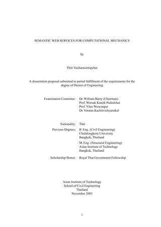
  • 29. CHAPTER 4 WEB SERVICES 4.1 The Web Services Architecture Web Services (W3C, 2003d) is a new distributed computing architecture that uses the Internet as the medium for communication. The fundamental concept of Web Services is to build computer software by making use of Remote Procedure Calls (RPC) to objects or sub- routines over the Internet or a network. It differs from other previous distributed computing technologies in the use of platform-independent standards such as the Hypertext Transfer Protocol (HTTP) (Fielding et al., 1999) and the eXtensible Markup Language (XML) (Bray et al., 2000; Fallside, 2001; Thompson et al., 2001; Biron and Malhotra, 2001) which allow service providers to completely hide the implementation details from the clients. The clients need to know the Unified Resource Locator (URL) (Berners-Lee et al., 1994) of the service and the data types used for the method1 calls but does not need to know how the service is implemented in order to make use of it (Basha et al., 2002). The architecture of Web Services as described in (Basha et al., 2002) is presented as follows. Web Services architecture make extensive use of the XML language. The readers are referred to standard textbooks on XML such as Harold (2001) for detailed information. A typical model of Web Services architecture is illustrated in Figure 4.1. Three roles, namely, service provider, service consumer and service registry, and three operations, namely, publishing, finding and binding, are involved in the Web Services model. Descrip- tions of the roles are as follows: Service Provider – A service provider is an entity that creates the Web Service. Typically, the service provider exposes certain functionality in their organization as a Web Ser- vice for any organization to invoke. To reach full potential of a Web Service, the service provider needs to do two tasks. First, it needs to describe the Web Service in a standard format understandable by all organizations that will be using that Web Service. Next, it needs to publish the details about its Web Service in a central registry that is publicly available to everyone. Service Consumer – A service consumer is any organization that uses the Web Service provided by a service provider. The service consumer can know the functionality of a Web Service from the description made available by the service provider. To retrieve these details, the service consumer makes a search in the registry where the service provider had published its Web Service description. The service consumer is able to get from the service description the description of the mechanism to bind to the service provider’s Web Service and in turn to invoke that Web Service. Service Registry – A service registry is a central location where the service provider can list its Web Services, and where a service consumer can search for Web Services. Service providers usually publish their Web Service capabilities in the service registry for service consumers to find and then bind to their Web Service. Information such as organization details, the Web Services that it provides, and the brief details about each Web Service including technical details is typically stored in the service registry. As mentioned above, three operations fundamental to Web Services architecture are “finding”, “binding”, and “publishing”. The architecture aims to achieve inter-application 1A subroutine in object-oriented programming paradigm 21
  • 30. Find Service Registry Publish Service Bind Service Provider Consumer Web Service Description Figure 4.1: Conceptual Web Services Model (Basha et al., 2002) communication irrespective of the programming language the application is written in, the platform the application is running on, etc. To make this happen, the standards for each of these three operations and a standard way for a service provider to describe their Web Service irrespective of the programming languge used are needed. These standards are listed as follows: • A standard way to describe Web Services – The Web Service Description Language (WSDL) (W3C, 2001) is a standard that uses XML format to describe Web Services. The WSDL document for a Web Service defines the methods that are present in the Web Service, the input/output parameters for each of the methods, the data types, the network transport protocol used and URL of the end point at which the Web Service will be hosted. • A standard protocol to publish or find Web Services – The Universal Description, Discovery, and Integration (UDDI) standard (OASIS, 2002) provides a way for service providers to publish details about their organization and the Web Services that they provide to a central registry. It also provides a standard for service consumers to find service providers and details about their Web Services. Publication of the details is the “description” part of the UDDI and finding of such details is the “discovery” part of it. • A standard protocol for applications to bind to Web Services – The Simple Object Access Protocol (SOAP) (W3C, 2000) is a lightweight2 XML mechanism used to exchange information between applications regardless of the operating systems, pro- gramming languages, or object models employed in developments of the applications. The roles of SOAP, WSDL and UDDI within the context of Web Services architec- ture is presented in Figure 4.2. Each of the layered blocks in the figure builds upon the block beneath it. The labels shown on the left identify the concepts in the architecture and those on the right identify actual technologies being used in the implementations. The Transport Network layer is responsible for making Web Services accessible by using any of the trans- port protocols available such as the Hypertext Transfer Protocol (HTTP) and the Simple Mail 2 with small amount of overhead instructions 22
  • 31. Service Publication/Discovery UDDI Service Description WSDL XML Messaging SOAP HTTP, SMTP, FTP or HTTPS Transport Network TCP/IP Figure 4.2: Roles of SOAP, WSDL and UDDI in Web Services Architecture (Basha et al., 2002) Transfer Protocol (SMTP) (Klensin, 2001). The XML Messaging layer defines the message format that is used for application communication, with SOAP as the standard commonly used by Web Services. The Service Description layer provides a mechanism for a service provider to describe the functionality that a Web Service provides. The Service Publication TM and Discovery layer acts like a Yellow Pages where service providers publish the links to their WSDL documents describing the Web Services they provide and the instructions to TM make use of them. Service consumers, on the contrary, use these Yellow Pages to search for Web Services suitable for their needs and make use of them according to the instructions given by service providers. 4.2 Applications of Web Services in Scientific Computing Web Services has been involved in many area of scientific computing ranging from computational infrastructure developments (Chiu et al., 2002; van Engelen, 2003) to finite element analysis a coupled fluid, thermal, and mechanical fracture problem (Chew et al., 2003). Chiu et al. (2002) investigated the limitations of SOAP for high-performance scien- tific computing and presented an improved implementation of the SOAP specification more suitable to applications in this area. van Engelen (2003) investigated the usability, interoper- ability, and performance issues of SOAP/XML-based Web Services for scientific computing and addressed key issues important for deployment of high-performance and mission-critical services. It was reported that a successful deployment of Web Services in scientific comput- ing may be achieved by limiting the communication overhead of XML encoding through defining optimized XML data representations and by applying message chunking, compres- sion, routing, and streaming techniques in the communication between services. In Chew et al. (2003), crack propagation of a rocket engine segment subjected to high Reynolds num- ber, chemically reacting gas flow was studied. One of the most significant efforts in this area is the standardization attempt by the Global Grid Forum to create the Open Grid Service Architecture specification (OGSA) (Foster and Gannon, 2003), which is the global standard for interoperations among the grid community. According to Foster and Gannon (2003), 23
  • 32. SOAP and WSDL, two important components of Web Services, are adopted in this standard. Since there are already a significant number of scientific computing projects that rely on grid computing infrastructures, with NASA’s Information Power Grid and the TeraGrid as key projects in the area, imposition of such a standard implies a significant increase in the number of scientific computing applications that rely on Web Services technology. 24
  • 33. CHAPTER 5 THE SEMANTIC WEB 5.1 General The World Wide Web has turned into a hyper-library where accesses to the very large collection of information are ubiquitous, in both academic and non-academic worlds. The success of the Web may be reflected by the ever-increasing electronic versions of documents such as books, magazines, and journals. Since its invention in 1992 (Berners-Lee et al., 1992), HyperText Markup Language (HTML) (W3C, 1999a) has been the standard for pub- lication of documents on the Web. HTML is a collection of tags that are used to specify how a document is to be displayed on web browsers. Examples of HTML tags are those presented in Figure 5.1, such as <title>, <b>, and <table> that tell web browsers to dis- play the title of a web page, a text in bold typeface, and a table with specified numbers of rows and columns, respectively. One drawback of using HTML as the sole representation of documents is that, from the point of view of computers, no semantics1 can be extracted from such documents. Pieces of information embedded inside a document can be extracted by hu- mans reading them on web browsers but, to computers, the document itself does not provide much information other than a stream of characters with extra specifications on how they are to be rendered on web browsers. The HTML code in Figure 5.1 would be rendered as a table of mechanical properties for steel, aluminum, and copper as shown in Figure 5.2. Humans would have no trouble understanding that the modulus of elasticity of steel, aluminum, and copper, are 200 GPa, 70 GPa, and 120 GPa, respectively. With some basic background in en- gineering, human readers would also understand that these moduli of elasticity are specific properties of materials, which are used to relate stresses to strains developed inside them. Computers, on the other hand, would have no clue what the contents of this table mean and, as a consequence, could not make any use of them unless programmers explicitly specify how information from a particular HTML code of a particular web site can be extracted and used. In the example in Figure 5.1, to extract the modulus of elasticity of aluminum from the table, the computer may be programmed to use a pattern matching technique to get the character string (not a number) that lies between the second pair of <td>, </td> tags located inside the pair of <tr>, </tr> tags whose first pair of <td>, </td> tags contains the string aluminum. The example above is for the case that involves only one document on the Web. In the real world, searching for information on the Web often involves multiple documents and data sources. This means that, in a non-automated way, humans would have to read and examine these web pages and extract the embedded information, or, in an automated way, programmers would have to examine various patterns of HTML codes and provide hard- coded routines to extract information from various web pages. These tasks are tedious if they involve ten to twenty documents from restricted searches on web sites and are next to impossible on unrestricted searches over the Internet, where a search for “mechanical TM properties” on Google returns hundreds thousands of web pages, with a potential that the HTML code of each one is constantly being changed due to the decentralized architecture of the Web. The Semantic Web (Berners-Lee et al., 2001), a vision for the next generation of the World Wide Web, is the Web in which information presented are useful not only for humans 1 the relationship between words or symbols and their intended meanings (Microsoft, 1997) 25
  • 34. <html> <head> <title>Material Properties</title> </head> 5 <body> <b>Mechanical properties</b> of materials are presented as follows: <br/> <table> <tr> 10 <td>Material</td> <td>Young’s Modulus (GPa)</td> <td>Yield Stress (MPa)</td> </tr> <tr> 15 <td>Steel</td> <td>200</td> <td>240</td> </tr> <tr> 20 <td>Aluminum</td> <td>70</td> <td>60</td> </tr> <tr> 25 <td>Copper</td> <td>120</td> <td>260</td> </tr> </table> 30 </body> </html> Figure 5.1: Example of an HTML Document ' $ Mechanical properties of materials are presented as follows: Material Young's Modulus (GPa) Yield Stress (MPa) Steel 200 240 Aluminum 70 60 Copper 120 260 & % Figure 5.2: HTML Document in Figure 5.1 as Rendered on a Web Browser 26
  • 35. <rdf:RDF xmlns:rdf="http://www.w3.org/1999/02/22-rdf-syntax-ns#"> <rdf:Description about="http://www.computings.org"> <Creator>Glenn Smith</Creator> 5 </rdf:Description> </rdf:RDF> Figure 5.3: Example of an RDF Description but also machines. According to an article by Tim Berners-Lee, the inventor of the Web, and his colleagues (Berners-Lee et al., 2001), by augmenting Web pages with data targeted at computers and by adding documents solely for computers, we would be able to transform the Web into the Semantic Web where computers find the meaning of semantic data on a web page by following hyperlinks to definitions of key terms and rules for reasoning about them logically. Computers will be able to understand pieces of information on web pages rather than merely presenting them to users, and will be able to manipulate such information on their own. Explicit representation of the semantics underlying data, programs, pages, and other web resources, will enable a knowledge-based web that provides a qualitatively new level of service. Automated services will improve in their capacity to assist us in achieving our goals by understanding more of the content on the Web and thus provide more accurate filtering, categorization, and search of information sources (Ding et al., 2002). Eventually, computers could then be able to help us make better use the enormous information scattered on the Internet in a more efficient and less tedious way. According to (Berners-Lee et al., 2001), for the Semantic Web to function, computers must have access to structured collections of information and sets of inference rules that they can use to conduct automated reasoning. In artificial intelligence, such collections are called knowledge representation systems. Enabling such systems on the Web involves syntactic and semantic descriptions of data. Syntactic description is achieved by making use of the eXtensible Markup Langauge (XML) which allows users to add arbitrary structure to their documents by using tags, the hidden labels such as <youngs modulus> or <yield stress> that annotate web pages or sections of text on a page. Computer programs can make use of these tags in many ways but programmers would also have to know in advance the intended meaning of each tag, which is created, adopted, or used by document writers, as XML does not say anything about these meanings. Semantic description, the meaning description of an XML tag, is expressed by on- tology representation languages such as the Resource Description Framework (RDF) (W3C, 1999c) and DAML+OIL (DAML, 2001). Ontologies are encoded in sets of triples in a gram- matical form like the subject, verb and object of an elementary sentence. The triples can be written using XML tags. For example, in RDF, a document makes assertions that a particular thing (such as a person) has properties (such as “is the author of”) with certain values (such as a Web page). An example of RDF descriptions using XML tags is shown in Figure 5.3. In the following sections, RDF and DAML+OIL ontology representation languages as well as the mechanisms to make inferences on ontologies will be presented. 27
  • 36. 5.2 Resource Description Framework (RDF) 5.2.1 Introduction The Resource Description Framework (RDF) is an XML application2 for representing information about resources on the World Wide Web. RDF was first developed for represent- ing metadata about Web resources, such as the title, author, and modification date of a Web page, but, by generalizing the concept of a Web resource, RDF can also be used to represent information about things that can be identified on the Web, even if they cannot be directly retrieved on the Web. Intended for situations in which information needs to be processed by applications rather than being displayed to people, RDF provides a common framework for expressing the information such that it can be exchanged without loss of meaning. In the following, concepts about RDF, as described in W3C (2003b), will be presented. 5.2.2 An RDF Statement RDF is based on the idea that the things being described have properties which have values, and that resources can be described by making statements that specify those prop- erties and values. For a particular statement, the part that identifies the thing the statement is about is called the subject. The part that identifies the property of charateristic of the subject that the statement specifies is called the predicate. The part that identifies the value of that property is called the object. RDF statements may be represented in both graphical and non-graphical ways. Figure 5.3 presented earlier is an RDF statement about the au- thor of a Web site encoded in RDF/XML, which is the XML version of RDF representation and is the machine-processable way to represent an RDF statement. The English statement corresponding to the figure is “http://www.computings.org has a Creator whose value is Glenn Smith.” The subject for this statement is http://www.computings.org. The predicate is Creator and the object is Glenn Smith. 5.2.3 Identification of Resources RDF uses Uniform Resource Identifiers (URIs) (Berners-Lee et al., 1998), the gen- eralization of the Uniform Resource Locators (URLs) (Berners-Lee et al., 1994) commonly used on web browsers, as the basis of its mechanism to uniquely identify subjects, predi- cates, and objects in statements. To be precise, RDF uses URI references (URIref), which is a URI with an optional fragment identifier separated by the symbol #. For example, the URI reference http://www.computings.org/peoples.html#85740 consists of the URI http://www.computings.org/peoples.html, which is a web page that contains informa- tion about many people, and the fragment identifier 85740, which specifically identifies the information about people whose identification number is 85740. RDF defines a resource as anything that is identifiable by a URI reference. According to the specification (Berners-Lee et al., 1998) URIs and URIrefs can be used to identify things that can be accessed online as well as the ones that cannot. Thus, using URIrefs allows RDF to describe practically anything, and to state relationships between them as well. 5.2.4 The RDF Model Although RDF may be represented in graphical and non-graphical ways, RDF state- ments are fundamentally modeled as graphs. RDF models statements as nodes and arcs in a graph. An RDF statement is represented by (1) a node for the subject, (2) a node for the 2 A markup language defined by XML. XML is a meta-markup language or the language that is used to define markup languages (Harold, 2001). 28
  • 37. http://www.computings.org/index.html http://purl.org/dc/elements/1.1/creator http://www.computings.org/staffid/85740 Figure 5.4: A Simple RDF Statement (adapted from W3C, 2003b) object, and (3) an arc for the predicate, directed from the subject node to the object node. Groups of statements are represented by corresponding groups of nodes and arcs. Figure 5.4 shows an example of a simple RDF statement. Figure 5.5 shows a group of RDF statements that modify the statement in Figure 5.4 with the following statements: http://www.computings.org/index.html has a creation-date whose value is August 16, 1999. http://www.computings.org/index.html has a language whose value is English. The name of the staff specified by http://www.computings.org/staffid/ 85740 is Glenn Smith. He is 27 years old. Objects in RDF statements may be either URIrefs or literals, which are constant val- ues of character strings to represent property values. Literals may not be used as subjects or predicates in RDF statements. In RDF graphs, nodes that are URIrefs are shown as ellipses whereas nodes that are literals are shown as boxes. URIrefs are used in Figures 5.4 and 5.5 to explicitly specify, for example, that the predicate creator is to be strictly interpreted by the definition in http://purl.org/dc/ elements/1.1/creator, and the object is strictly the staff of Computings.org whose iden- tification number is 85740. Using URIrefs as subjects, predicates, and objects in RDF state- ments supports the development and use of a shared vocabulary on the Web, since people can discover and begin using vocabularies already used by others to describe things, thus reflecting a shared understanding of concepts. 5.2.5 Defining RDF Vocabularies RDF provides a way to express statements about resources using named properties and values. However, it lacks the capability to define terms or vocabularies to describe specific classes of resources nor the properties to be used specifically on them. Such classes and properties can be described as an RDF vocabulary by using RDF Schema (RDFS) (W3C, 2003c). RDF Schema provides the facilities needed to describe classes and properties, and to indicate which classes and properties are expected to be used together. It provides a type system for RDF, which is similar in some aspects to the type systems in object-oriented programming languages. RDF Schema allows resources to be defined as instances of one or more classes and allows classes to be organized in a hierarchical fashion. 29
  • 38. http://www.computings.org/index.html http://purl.org/dc/elements/1.1/creator http://www.computings.org/terms/creation-date http://www.computings.org/terms/language August 16, 1999 http://www.computings.org/staffid/85740 English http://www.computings.org/terms/name http://www.computings.org/terms/age Glenn Smith 27 Figure 5.5: Several RDF Statements about Resources (adapted from W3C, 2003b) Classes RDF Schema uses classes to refer to the kinds of things to be described. A class in RDF Schema corresponds to the generic concept of a type or category, or a class in object- oriented programming languages. RDF classes can be used to represent any category of things, ranging from people, Web pages, document types, to abstract concepts. Classes are described by using the RDF Schema resources rdfs:Class and rdfs:Resource, and the properties rdf:type and rdfs:subClassOf. The resources that belong to a class are called the instances to that class. As an illustration, a hierarchy of classes in RDF Schema in graph notation and the corresponding RDF/XML encoding are presented in Figures 5.6 and 5.7. An RDF/XML encoding that represents an instance of a class defined in the figures is also shown in Figure 5.8. Properties RDF Schema uses the RDF class rdf:Property, and the RDF Schema properties rdfs:- domain, rdfs:range, and rdfs:subPropertyOf to specifically describe properties that character- ize classes of things. All properties in RDF are described as instances of class rdf:Property. RDF Schema also provides vocabulary for describing how properties and classes are in- tended to be used together in RDF data, with the RDF Schema properties rdfs:range and rdfs:domain as the most important information to describe application-specific properties. The rdfs:range property is used to restrict that the values of a particular property are instances of a specified class or given by a specific type of literals. The rdfs:domain prop- erty is used to indicate that a particular property applies to a specified class. Data types of literals specified in rdfs:range are defined externally to RDF and RDF Schema. Data types may be defined by XML Schema data typing mechanisms (Biron and Malhotra, 2001) and are referred to in RDF statements by their URIrefs. Statements with rdfs:range serve to document the existence of data types and to indicate explicitly that they are to be used in the schemas. Similar to classes, RDF Schema also provides a way to make specializa- tion on properties. The specialization relationship between two properties is described by 30