Boost Fertility New Invention Ups Success Rates.pdf
3 dmobilenavigationdesign
1. Nurminen,A., & Oulasvirta, A. (2008). Designing interactions for navigation in
3D mobile maps. In L. Meng, A. Zipf, S. Winter (Eds.), Map-based Mobile Ser-
vices: Design, Interaction and Usability, Springer, Lecture Notes in Geoinfor-
mation and Cartography, London, pp. 198-224.
THIS IS THE AUTHOR’S COPY OF THE PAPER, PLEASE CONSULT THE
BOOK FOR CITATION
1 Designing Interactions for Navigation in 3D
Mobile Maps
Antti NURMINEN1, Antti OULASVIRTA2
1Helsinki University of Technology, Finland
2Helsinki Institute for Information Technology HIIT, Finland
Abstract. Due to their intuitiveness, 3D mobile maps have recently emerged as
an alternative to 2D mobile maps. However, designing interactions for naviga-
tion in a 3D environment using a mobile device is non-trivial. Challenges are
posed by the severe limitations of the mobile user interface and of the capacities
of the mobile user. This chapter analyses the problem of degrees of freedom:
how to make navigation quicker and more intuitive by the means of restricting
and guiding movement, yet enabling unrestricted access to all reasonable
points-of-interests. Insights from empirical studies of mobile map interaction
are presented, in the form of a model of interactive search, to draw requirements
for interaction design. Then, the design of controls, landmarks, cameras, inter-
est fields, routes, paths etc. are analysed and several higher-level navigation
metaphors are discussed. We propose ways to support spatial updating, rapid
alignment of physical and virtual spaces, and overcoming the keyhole problem.
A working prototype system is used to illustrate different solutions alongside
with alternative designs, weighing their pros and cons.
1.1 Introduction
Recent advances in the processing capabilities and interface technologies of mobile
devices have brought about a situation where 3D mobile maps are increasingly realis-
tic. During the past five or so years, several developers have presented working proto-
types of 3D mobile maps and empirically compared them to 2D maps. Various user
benefits have been identified, such as fun, recognisability, efficiency, intuitiveness,
and decreased memory load (e.g., Burigat and Chittaro 2005, Laakso 2002, Oulas-
virta, Nurminen, and Nivala submitted, Rakkolainen and Vainio 2001, Vainio and Ko-
tala 2002).
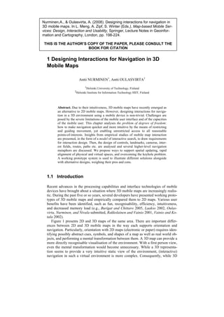
Figure 1 presents 2D and 3D maps of the same area. There are important differ-
ences between 2D and 3D mobile maps in the way each supports orientation and
navigation. Particularly, orientation with 2D maps (electronic or paper) requires iden-
tifying possibly abstract cues, symbols, and shapes of a map as well as real world ob-
jects, and performing a mental transformation between them. A 3D map can provide a
more directly recognisable visualisation of the environment. With a first person view,
even the mental transformation would become unnecessary. While a 3D representa-
tion seems to provide a very intuitive static view of the environment, (interactive)
navigation in such a virtual environment is more complex. Consequently, while 3D
2. visualisations appear as an appealing option for designers, a major problem lies within
the meaningful and efficient control over such visualisations.
Furthermore, there are non-trivial design problems arising from the characteristics
of mobile human-computer interaction (HCI). The key challenge in design is the
problem of degrees of freedom (DOFs): how to balance freedom of movement with
efficiency of navigation. The number of DOFs needed to completely control a 3D
view exceeds the amount of input controls in mobile devices, and the problem is ac-
centuated by the fact that mobile devices have small displays, which implies that
more motion is needed to gather the same amount of information. Moreover, as mo-
bile users’ capability to invest uninterrupted attention in a mobile device is known to
be compromised (Oulasvirta et al. 2005), the interface should allow them to display
what ever is currently needed as quickly and easily as possible, without complicated
manoeuvring that requires all of the user’s attention.
This book chapter summarises three years of research and development efforts on
m-LOMA, a 3D mobile map of an urban environment (the city centre of Helsinki)
(Nurminen 2006). Our goal has been to create an efficient interface for navigating in a
3D view with the limited resources available. We first review general goals for de-
signing a 3D navigation interface specifically for mobile devices. A model of user in-
teraction with 3D maps is then presented. Subsequently, we formalise the problem of
mapping controls to manoeuvring, and proceed to present mobile input devices along
with those of their innate and practical problems that should be considered in the in-
teraction design. We then present and discuss several manoeuvring schemes. The
main part of the text concerns real and simulated cases and introduces a set of rules,
tools, and metaphors that can ease navigation.
Fig. 1. A 2D and a 3D map of the same area.
1.2 Definitions
The term 3D map has been used widely in the literature, assuming an intuitive defini-
tion. However, this term can be applied to representations whose source data is purely
two-dimensional. Correspondingly, a data set which is in fact three-dimensional can
be visaulised in various fashions resembling a 2D map.
Based on our observations, we have identified two processes involved in producing
3D maps. First, a three-dimensional representation of a physical environment is
3. formed. This representation can be a data structure, such as a 3D model, where three-
dimensional shapes and visual characteristics are stored. The modelling process can
simplify the real-world geometry and its visual features, but maintains the spatial rela-
tions of objects. Metadata can be included in the representation. Second, this repre-
sentation is visualised as a two-dimensional image, depicting the three-dimensional
aspects of the original environment and conveying the spatial relations of the physical
structures of the area. The selected visualisation strategy to yield a final map may de-
pend on context and purpose, emphasising different characteristics of the environ-
ment. We define a 3D map to be a two-dimensional visualisation of a three-
dimensional representation of a physical environment, emphasising the three-
dimensional characteristics of this environment.
3D maps may have a variety of characterstics, depending on their contents, pur-
pose, visualisation and other features. Table 1 presents a common set of such attrib-
utes. In addition, there may be other run-time selectable features and modes, such as
perspective or orthogonal projection, first-person view, or visualisation styles. For ex-
ample, thematic visualisation could employ cartographic conventions to colour the
buildings based on their type (landmark, office building, shopping mall) instead of
applying textures to the façades (Plesa and Cartwright 2007).
By our definition, a photograph is not a 3D map, as it is not created by a two-stage
process, even though it is visually indistinguishable from the theoretical ideal map. A
2D road map with a perspective projection would not be a 3D map, as the data struc-
tures are not truly three-dimensional. Such a map could be called a “2.5D” map. 3D
geometry, portrayed directly from above with orthogonal projection, could be classi-
fied as a 2D map, unless the visualisation provides clearly three-dimensional charac-
teristics, such as shadows. Classification of maps based on procedural models would
depend on the resulting model geometry and the chosen visualisation method.
Attribute Explanation
The data set and its visualisation exactly match the real world;
Ideal
a single image is indistinguishable from a photograph.
Map data is visualised in a realistic manner, in an attempt to
Realistic approach the ideal representation. Typically, this involves use
of textures created from the real environment by digitisation.
Visualisation is performed on-the-fly instead of displaying
Real-time rendered
pre-rendered animation sequences or images.
Allows users to control the position and direction of the vir-
Navigable
tual camera.
A navigable, real-time rendered 3D map, responding to users’
Interactive
queries and providing navigation-assisting features.
Contains time dependent elements other than the virtual cam-
Dynamic era, such as positions of GPS tracked users, public transporta-
tion etc.
Emphasises the computerised means in producing the 3D
Electronic
view instead of a drawing or painting.
4. Urban/outdoor/indoor Description of the represented environment.
Electronic, running on a mobile, battery-operated device, such
Mobile as a PDA or smart phone. Also implies navigability, interac-
tivity and real-time rendering.
A stereo projection system, where a separate view is produced
Immersive for each eye to achieve an illusion of being immersed in the
environment.
Table 1. Common 3D map attributes.
1.3 General requirements for mobile navigation interfaces
The design of a mobile map suited for users’ needs is a challenging task, and may re-
quire several trade-offs (Meng and Reichenbacher 2005). With mobile 3D maps, the
situation is further accentuated. This section summarises user requirements for the de-
sign of mobile navigation interfaces. A real-life example of cumbersome interaction is
presented.
1.3.1 Support for use in multitasking situations
When a user operating an application is completely concentrating on the task, un-
aware of the existence of the interface, the interface is said to be transparent to the
user (Norman 1988). This should be achieved also for 3D navigation. Mobile users
have short attention spans, in extreme mobile situations in the order of just few sec-
onds (Oulasvirta et al. 2005). Therefore, the mobile application should provide
prompt aid. Moreover, users’ operative modalities are often limited; for example, they
may need to operate with one finger only, or may not hear anything due to environ-
mental noise. In addition, users may have limited time or motivation to learn complex
controls. To summarise, we assign three goals for mobile controls in pursue of trans-
parency:
• minimise cognitive load (as defined by working memory load, amount or dura-
tion of cognitive task processing, or complexity of mental computations),
• minimise motor effort and procedural complexity,
• minimise use of time.
1.3.2 Support for navigation
While experiencing a city, the user may be performing one of the many tasks related
to navigation. She may be exploring the environment, observing interesting features,
searching for something, or conducting a naïve search, that is, extensively and at
times exhaustively searching the environment (Darken and Sibert 1996). Or, she may
already know the approximate position of a target, proceeding for a closer look, on a
5. primed search (Darken and Sibert 1996). Perhaps a route has been provided, and the
user is attempting to maintain orientation while manoeuvring towards the target, or is
spotting the next turn point. While the user moves and observes the environment, she
simultaneously develops a cognitive map (Downs and Stea 1977). At all times, the
user attempts to maintain a sense of orientation and avoid any situations that might
lead to disorientation.
To support navigation, we assign the following goals for the 3D view:
• maximise information that helps orientation,
• maximise information that helps performing the current task,
• minimise information that leads to disorientation,
• maximise information that helps forming an accurate cognitive map.
Fulfilling these objectives ensures that the user
• does not get lost,
• is able to find and visit all places of interest,
• is able to re-visit places,
• feels familiar with the space.
1.3.3 Support for embodied interaction
In general, what makes mobile maps distinct and different from typical virtual envi-
ronments (VEs)—such as virtual reality and desktop-based navigation systems—is
that the user is physically embedded in the world that the virtual model represents.
The dual presence is not symmetric: the roles of eye, head and body movements for
acquiring information are emphasised in physical environments (PEs), whereas VEs
are typically associated with decreased field of view and low fidelity of landmarks
and non-visual cues. There are four implications of this.
First, what makes mobile maps different from VEs and map artefacts is the strong
influence of the keyhole property (Woods and Watts 1997). The keyhole property
means that “the number of potential views is much greater than the physical size of
the available viewports” (p. 619). Since direct recognition is often not possible be-
cause of this property unless the target happens to be on the display, users have to
move within the space or spaces to achieve a position in which the target can be
found. In contrast to VEs, mobile maps assume search within two spaces instead of
just one.
Second, because of the keyhole property, the alignment of the representation with
the represented space is often difficult. Alignment is important for orientation, be-
cause human spatial knowledge is known to be viewpoint-dependent. This also con-
cerns knowledge of dynamic scenes (Garsoffky, Schwan, and Hesse 2002). Hence,
when objects in a map do not correspond to stored representations, the user has to
transform or rotate the representation, which entails mental or physical effort (Levine
1982). Mou and McNamara (2002) elaborate this view by arguing that spatial memo-
ries are defined with respect to intrinsic frames of reference, which are selected on the
basis of egocentric experience and environmental cues. The availability of cues is ex-
actly where 3D maps differ from other representations. It is also worth mentioning
that viewpoint-dependence of spatial knowledge may be exaggerated in the case of
6. mobile maps where the size of display is small. Presson, DeLange, and Hazelrigg
(1989) claim that small displays do not "afford", as does movement in PE, large spa-
tial arrays to be coded by the perceptual system during movement. Moreover, they do
not support as much perceptual exploration and scanning (cf. Roskos-Ewoldsen et al.
1998).
Third, because the use of mobile maps is supposed to be possible when the user is
moving, the map’s support for spatial updating—the mechanisms involved in locating
positions in space relative to oneself after a given spatial transformation—is empha-
sised (Wraga 2003). Wang and Brockmole (2003) have examined what happens when
the environment is divided into nested structures (e.g., city consisting of district con-
sisting of blocks). They noted that spatial updating is not carried out in all structures
simultaneously nor with the same accuracy. When switching to a new environment,
one often loses track of one's position relative to old environments. Providing alterna-
tive views in 3D might support the user in updating and re-constructing such struc-
tures when needed.
Fourth, the small scale of transformations (e.g. Golledge 1999) in mobile maps
may lower the informativeness and recognisability of objects. Only recognisable ob-
jects can be utilised as landmarks that help the tasks of mapping and orientation.
Therefore, 2D is different from 3D by trading off informativeness of an object to in-
formativeness of an area. Witmer, Sadowski, and Finkelstein (2002) showed that add-
ing aerial views enhances users’ ability to navigate through VE. Furthermore, in order
to help in understanding the relationship between the virtual and the physical, land-
marks in the virtual model also have to be distinctive (stand out), which depends on
the visual as well as the structural qualities of the view (Sorrows and Hirtle 1999).
In Section 1.5, several solutions to these problems are presented and analysed.
1.3.4 3D navigation with direct controls: example from a field study
To exemplify an inefficient search strategy, let us present a case of manoeuvring in an
urban canyon with direct mapping of controls to the navigation state (See 1.5.1.). The
case is taken from our field experiment (Oulasvirta, Nurminen, and Nivala submit-
ted), at a time when the subject has completed about half of the tasks. In that experi-
ment, the subjects were shown a target building in the virtual space and asked to
move to the corresponding object in the physical space.
7. A B C
D E F
Fig. 2. Analysis of a real navigation episode. Explanation given in text.
(Adopted from Oulasvirta, Nurminen, and Nivala submitted)
A test subject1 located at A attempts to manoeuvre a 3D map view from A to B
(Figure 2A), to spot a landmark known to her in advance. The 3D map is running on a
PDA with initial orientation of Figure 2B. The map view is controlled by the PDA's
joypad, which switches the viewpoint forward or backward, and rotates it left or right,
as long as the control is held down. Manipulating the joypad moves the viewpoint at a
constant speed and rotates it at a constant angular velocity. Additional controls affect
elevation and pitch, but roll is fixed to a constant up direction. Thus, the subject has
four degrees of freedom available for controlling the viewpoint. In the beginning of
this task, the subject orients to the environment, spotting a recognisable façade (Fig-
ure 2D in m-LOMA and 2C in the real world). The subject then determines a direc-
tion of movement and starts to manoeuvre along a road. After two blocks, the subject
finds the target landmark and stops. Figure 2E presents the path and points of orienta-
1 The subject had trained the controls 15 mins during a training session, and about 30 mins dur-
ing similar tasks at field before this one, without prior experiences of 3D games or 3D maps.
8. tion resulting from performing the task. Figure 2F presents the related joypad state as
a function of time. To perform this simple task, the user performed a total of 20 rota-
tions and 10 forward movements, using only two degrees of freedom from the avail-
able four. The subject did not move backward. The task took 135 seconds to com-
plete, and the controls were used in two sequences: 5 seconds during initial
orientation and 29 seconds during manoeuvring towards the target. The remainder of
the time, the subject observed the environment and waited for a car and a tram to pass
(the tram remained in view for almost a minute). All actions on controls were per-
formed sequentially.
The presented case contains three of the four stages of navigation presented by
Downs and Stea (1977): 1) the initial orientation at start, 2) manoeuvring towards a
target and 3) recognising the target. The final stage, 4) maintaining the orientation to
the target, is not relevant, as the distance to travel after the target has come into view
is short and the route straightforward. The task appears simple, but the actual ma-
noeuvring by the subject is unnecessarily complex. At several points, the viewpoint
approaches a wall, and correcting the orientation provides only a temporary solution,
as yet another correction must soon take place. Even when the subject simply rotates
around one axis, a number of button presses is required to find a suitable view.
This real episode taken from our data clearly illustrates the fact that four degrees of
freedom are too much for the majority of users. In Section 1.5 we will go through
several interface solutions that address this problem. We shall make a distinction be-
tween manoeuvring—actions towards a subgoal such as the orientation or moving one
block, and micro-manoeuvring—corrective or adjusting actions that happen within a
manoeuvre (such as rotating back and forth several times to find a suitable view or di-
rection of travel).
1.4 A model of interactive search on mobile maps
Before turning to concrete design solutions to the DOF problem, we need to explain
some aspects of how users interact with mobile maps in real life situations. The model
of Oulasvirta, Nurminen, and Nivala (submitted) is rephrased here.
In their influential paper, Kirsh and Maglio (1994) distinguished between two
kinds of action: pragmatic and epistemic. The former refers to action that transforms
the physical problem space, for example moving a disk from one pole to another in
the Tower of Hanoi task. The latter refers to action that does not directly contribute to
the solving of the problem; rather, its objective is to have an effect on the cognitive
state of the agent itself. Epistemic action can have three functions:
1. to reduce time complexity (how long something takes),
2. to reduce space complexity (how much cognitive processing is required),
3. to reduce uncertainty (how certain is an outcome) in the problem.
For example, Tetris players often quickly rotate a zoid around one or several times
after it appears in an attempt to see how the zoid fits the landscape beneath it. This in
effect changes the task from mental rotation (slow) to recognition (fast).
9. 1.4.1 Pragmatic search action
Fig. 3. A model of interactive search with mobile maps as pragmatic action
Figure 3 presents the model of pragmatic search (cf. Jul and Furnas 1997). In the
core of the model are 1) a match process taking care of the comparison between the
target description (kept in mind) and the perceived space and 2) a motor action proc-
ess that transforms the space according to the cue-search strategy. The search-action
loop involves acting based on a selected strategy for searching for a cue (e.g., search-
ing for a certain rooftop shape by scanning horizontally while keeping view toward
rooftops). Carrying out the strategy produces a change in the state of the world. This
new state is perceived and a new match is attempted. A failed match process leads
back into the search-action loop. Importantly, search action can take place both in the
virtual and the physical world, unlike in VEs where the search always takes place in
the virtual space. When the current strategy does not produce satisfactory matches, it
has to be changed. This triggers the hypothesis-restructuring loop, which involves ac-
quiring a new target description by choosing a new cue in the source environment
(e.g., noticing that the target building is the lowest one). This does not always happen
as an internal process, but is often manifested in the subject physically returning to a
position where a new description of the target can be extracted or the earlier one
elaborated.
10. 1.4.2 Epistemic search action
Below, we report a total of seven behaviours, observed by Oulasvirta, Nurminen, and
Nivala (submitted), that can be interpreted as epistemic action rather than pragmatic
action (for visualisations of related search paths, see Figure 4):
1. Scanning the immediate context of the target, in order to elaborate the de-
scription of the target held in working memory (e.g., by looking at colours of
neighbouring buildings).
2. Scanning for landmarks such as statues, in order to elaborate the description
of the target or to use prior semantic and spatial information.
3. Egocentric positioning (locating oneself in the map), in order to utilize the
(stronger) representations of the PE in action for the VE.
4. Circling (walking around a full circle in VE) and viewing the buildings, thus
creating initial mental representations to support search later on.
5. Exploring the proximal area (e.g., moving around in an area of few blocks
from the starting position) in the first experimental trial to familiarise oneself
with the model, thus reducing search costs in the subsequent trials.
6. Peeking around a corner to identify action alternatives and familiarise one-
self with the surroundings, thus elaborating a representation of the vicinity
and reducing uncertainty in the upcoming trial.
7. Rotating: the view is quickly rotated horizontally in the beginning of the trial
to see the surrounding buildings. May serve egocentric positioning, landmark
search etc. (Similar to tactics 4, 5, and 6.)
But what is actually achieved by such epistemic actions from the perspective of the
task of finding a given target? We posit that there are three main functions of epis-
temic actions in interacting with a mobile map:
1. Improving cue descriptions. In some of the epistemic actions, the user scans
the target and its immediate neighbourhood. This can result in elaboration of
the mental representation of the target, which in turn can facilitate the subse-
quent match process (i.e., reduction of uncertainty).
2. Improving match process. Some of the epistemic strategies can be explained
as attempts to shift the processing burden from the limited and effortful
short-term working memory system by switching from mental computation
and maintenance to recognition. This strategy reduces uncertainty and de-
creases the time complexity of the task.
3. Improving search strategy and search action. Naturally, richer representa-
tions of the environment can participate in strategy selection and implemen-
tation of search action. For example, having a hypothesis of the target’s posi-
tion in relation to a landmark helps decisions on where to look. This can
make exhaustive scanning unnecessary. Such epistemic actions as exploring
and peeking in effect enhance the user’s possibility to know where to search
for the target by narrowing down the number of alternatives.
Implications of this descriptive user model to design are discussed in Section 1.5.
11. A B
C D
Fig. 4. Visualisations of users’ epistemic actions when searching a target. A) Learning
the model by exploring it from a top-down view; B) Walking around in a city square
and peeking around corners; C) Diving to street-level; D) Scanning, diving and scan-
ning at multiple levels, and walking around at the street level. From the movement log
data of the experiment of Oulasvirta, Nurminen, and Nivala (submitted).
1.5 Designing controls
An integral part of interaction design of navigation is the assignment of interface con-
trols to movement and action in the mobile map environment. Typical mobile devices
capable of running 3D graphics include personal digital assistants (PDAs) and smart
phones (see Figure 5). The controls offered by PDAs commonly include a touch
screen, a few buttons, and a joypad. The touch screen essentially provides a direct
pointing mechanism on a 2D plane, and a two-dimensional analog input. The touch
screen is operated by a stylus (a pointing stick). The buttons and the joypad are simple
discrete inputs. A direct text input method may be missing due to the lack of buttons,
12. but in that case, it is compensated by a virtual keyboard, operable by the stylus. A
smart phone commonly provides only discrete buttons. Usually a few of the buttons
are assigned to serve menu selections, and the rest are used either in typing text or di-
alling. Sometimes a joypad is provided for easier menu navigation. Exceptions to the-
ses prototypical examples exist, such as Nokia's Communicators, which include a full
keyboard. Some even contain both a keyboard and a touch screen, such as the Palm
Treo 650. Sometimes, a small keyboard can be attached to a PDA.
When a control state is propagated to, and received by an application, it is called an
input event. Mobile operating systems commonly prevent input events to be generated
in parallel, in a forced attempt to reduce possible control DOFs to 1; if one button is
down, the next possible event is the up event from that button. Platform-dependent
software development kits provide information to override this restriction.
Fig. 5. Mobile devices differ in the availability and layout of interfaces.
1.5.1 Mapping controls to navigation
The use of controls can be described as a mapping from control space G to navigation
space N. The navigation space can be described by a navigation state, which contains
all the variables related to navigation, including the camera position and orientation,
but also other variables such as speed, field of view (FOV) etc. The mapping can also
be called the function g of the input i, g: G N. We will call the number of relevant
user actions the control DOF and the navigation DOF the number of variables avail-
able for movement. The mapping provides movement on a guide manifold, a con-
strained subspace of the navigation space (Hanson and Wernert 1997). Discrete con-
trol inputs can be used for providing either a single event or multiple independent
discrete events. The mapping can depend on time, possibly in a nonlinear manner. A
2D input can be used similarly for a single 2D event, a discrete sequence of such
events (x, y)j, or a time dependent input (x,y,t). The motion derivatives (x’,y’) can also
be used as an input. If a control is given cyclic behaviour, the mappings depend on the
current cycle c of the inputs, g: Gci N. In this case, one button can control two or
more functions, each button release advancing the function to next on the cycle.
13. 1.5.2 Control delays
Physical controls provide a multitude of error sources. A single binary discrete event
may simply not occur when a button malfunctions. Time-dependent events are prone
to errors in timing. This can be caused either by the user or by the device. The user
simply may not be able to estimate timings accurately, but the same may be true for
the device. For example, with the Symbian operating system, the accuracy of the sys-
tem clock currently available to applications is less than 20ms (1/64s). There might be
constant minimum delays between events, caused by an operating system or a device
controller, or the controller output may be sampled at discrete intervals, causing
seemingly random output timings if the sampling rate is too low. Event propagation
from the OS to the application may also depend on available CPU, which may be
sparse during 3D rendering. For example, when a user presses a rotate button, render-
ing may start immediately, but when the button is released, it can take a while before
the rendering engine receives the event. If the user was attempting to aim at a certain
location, the possible crosshair would have passed the target. Combining these prob-
lems may yield a temporal, context-dependent inaccuracy of worse than 100ms.
While a coherent delay can be anticipated by a user, incoherent temporal errors are
difficult to adapt to. Moreover, all such delays contribute to degradation of user ex-
perience and, consequently, of usability. Therefore, identifying least-latency control
mechanisms is among the very first tasks of 3D interaction design for mobile devices.
1.6 Designing for navigation
Navigation is a process involving both mental and physical action, both way-finding
and movement (Darken and Sibert 1996). All movement requires manoeuvring, per-
forming a series of operations to achieve subgoals. Whereas manoeuvring in a 2D
view can be mapped to a few input controls in a relatively straightforward manner,
movement in a 3D world cannot. In addition to 3D position, one needs to specify 3D
orientation as well. Direct control over such a view would require simultaneous speci-
fication of at least six degrees of freedom. Generally, producing decent motion re-
quires even more variables, but a mobile device only has a few controls, of which the
user might want to use only one at a time. We assess that developing interaction for a
mobile 3D map depends heavily on solving this problem.
Therefore, when designing mobile maps, designers have to implement both carto-
graphic (amount of information presented, symbolisation, generalisation, simplifica-
tion) and interaction solutions, and this latter part is often overlooked. The model of
pragmatic action presented above suggests that the key way to minimise the possibil-
ity of choosing a failing strategy is to guide and direct the user to use those cues that
are known to be efficient in that particular model (e.g., for m-LOMA, façades of
buildings are more effective than street geometry). Similarly, designers can deliber-
ately make it more difficult to use those cues that are inefficient. Here, This design
strategy is called guidance.
Second, the model of epistemic action suggests supporting 1) the elaboration of the
target description, 2) the construction of a representation of the area in the PE, 3) the
14. use of prior knowledge, and 4) transforming the locus of task processing from work-
ing memory to perceptual modules. However, if guidance was optimally effective,
one could argue that users would not need to relapse to epistemic action and other
“corrective” behaviours. This, we believe, is not the case. Because of substantial indi-
vidual differences in representing the environment and in the use of cues and land-
marks (e.g., Waller 1999), and because information needs vary between situations, the
best solutions are those that support flexible switches between efficient strategies.
Manoeuvring in a VE can be realised with various levels of control over move-
ment. Table 2 presents a set of manoeuvring classes, in decreasing order of navigation
freedom. Beyond simply mapping controls to explicit manoeuvring, one can apply
metaphors in order to create higher-level interaction schemes. Research on virtual en-
vironments has provided several metaphors (see Stuart 1996). Many but not all of
them are applicable to mobile 3D maps, partly due to restrictions of the input methods
and partly due to the limited capacities of the user. Several methods exist for assisting
or constraining manoeuvring, for guiding the user's attention, or for offloading unnec-
essary micro-manoeuvring. For certain situations, pre-animated navigation sequences
can be launched via shortcuts. With external navigation technologies, manoeuvring
can be completely automatic. It is essential that the special circumstances and poten-
tial error sources typical to mobile maps are taken into consideration in navigation de-
sign. Selecting a navigation scheme or metaphor may also involve striking a balance
between support for direct search for the target (pragmatic action) on the one hand
and updating cognitive maps of the area (epistemic action) on the other. In what fol-
lows, several designs are presented, analysed, and elaborated in the framework of
navigation stages (Downs and Stea 1977) from the user's perspective.
Manoeuvring class Freedom of control
The user controls motion with a mapping depending on the
Explicit
current navigation metaphor.
The navigation system provides automatic supporting move-
Assisted ment and orientation triggered by features of the environment,
current navigation mode, and context.
The navigation space is restricted and cannot span the entire
Constrained
3D space of the virtual environment.
Animated view transition is triggered by user interaction, de-
Scripted pending on environment, current navigation mode, and con-
text.
Movement is driven by external inputs, such as a GPS device
Automatic
or electronic compass.
Table 2. Manoeuvring classes in decreasing order of navigation freedom.
15. 1.6.1 Orientation and landmarks
The first stage of any navigation task is initial orientation. At this stage, the user does
not necessarily possess any prior information of the environment, and her current po-
sition becomes the first anchor in her cognitive map. To match this physical position
with a 3D map view, external information may be necessary. If a GPS device is avail-
able, the viewpoint can be commanded to move to this position. If the map program
contains a set of common start points potentially known to the user, such as railway
stations or major bus stops, a selection can be made from a menu. With a street data-
base, the user can walk to the nearest intersection and enter the corresponding street
names. When the exact position is known, the viewpoint can be set to the current po-
sition, perhaps at street level for a first-person view. After resolving the initial posi-
tion, we further encourage assigning a visual marker, for example an arrow, to point
towards the start point. If the user's attempts at localisation fail, she can still perform
an exhaustive search in the 3D map to find cues that match her current view in physi-
cal world.
For orientation purposes, landmarks are essential in establishing key locations in an
environment (Evans 1980, Lynch 1960, Vinson 1999). Landmarks are usually consid-
ered to be objects that have distinguishable features and a high contrast against other
objects in the environment. They are often visible from long distances, sometimes al-
lowing maintenance of orientation throughout entire navigation episodes. These prop-
erties make them useful for epistemic actions like those described in Section 1.4. To
facilitate a simple perceptual match process, a 3D map should reproduce landmarks in
a directly recognisable manner. In addition, a 3D engine should be able to render
them from very far distances to allow visual searches over entire cities and to anchor
large scale spatial relations.
Given a situation where the start point has been discovered, or the user has located
landmarks in the 3D map that are visible to her in PE, the user still needs to match the
two worlds to each other. With two or more landmarks visible, or a landmark and lo-
cal cues, the user can perform a mental transformation between the map and the envi-
ronment, and triangulate her position (Levine, Marchon and Hanley 1984). Locating
landmarks on a 3D map may require excessive micro-manoeuvring, even if they are
visible from the physical viewpoint. As resolving the initial orientation is of such im-
portance, we suggest assigning a direct functionality to it. The landmark view would
automatically orient the view towards landmarks or cues as an animated view transi-
tion, with one triggering control (a virtual or real button, or a menu entry). If the cur-
rent position is known, for example with GPS, the landmark view should present both
the landmark and the position. Without knowledge of the current position, the same
control would successively move the camera to a position where the next landmark is
visible. Implementation of such functionality would require annotating the 3D model
with landmark information.
Sometimes, no major landmarks are visible or in the vicinity. In this case, other
cues must be used for matching the virtual and real environments, such as edges or
areas, street names, topological properties, building façades, etc. Local cues can be
unique and clearly distinguishable, such as statues. Some local cues, such as restau-
rant logos, are easy to spot in the environment even though they are not unique. We
suggest populating the 3D environment with local cues, minor landmarks, and provid-
16. ing the system with related annotation information. Again, a single control would
trigger camera animation to view the local cues. As this functionality draws the atten-
tion of the user to local cues, it requires knowledge of the user's approximate position
to be effective.
As landmarks are often large objects, we suggest assigning landmark annotation to
entire entities, not only to single points. An efficient 3D engine with visibility infor-
mation available can enhance the landmark view functionality by prioritising those
landmarks that are at least partially visible to the user in PE.
1.6.2 Manoeuvring and exploring
After initial orientation is obtained, the user can proceed with any navigational task,
such as a primed search (Darken and Sibert 1996). In a primed search, the target's ap-
proximate position is resolved in advance: a point of interest could be selected from a
menu, the user could know the address and make a query for coordinates, a content
database could be searched for keywords, or the user could have a general idea of the
location or direction based on her cognitive map. A primed search consists of the sec-
ond and the last of navigational stages, that is, manoeuvring close to the target and
recognising the target during a local browse. We suggest assigning another marker ar-
row to the target.
The simplest form of navigation would be immediately teleporting the viewpoint to
the destination. Unfortunately, instant travel is known to cause disorientation (Bow-
man et al. 1997). The commonly suggested way of travelling to long distances in gen-
erally straightforward direction is the steering metaphor, where the camera moves at
constant speed, or is controlled by accelerations. By controlling the acceleration, the
user can define a suitable speed, but doesn't need to use the controls to maintain it, re-
lieving motor resources for orientation. Orientation could indeed be more directly
controlled while steering, in order to observe the environment. In an urban environ-
ment, moving forward in a straight line would involve positioning the viewpoint
above rooftops in order to avoid entering buildings.
If the user is not yet willing to travel to a destination, she could start exploring the
environment as epistemic action, to familiarise herself with it. Again, controls could
be assigned according to the steering metaphor. For a better overall view of the envi-
ronment, the user should be allowed to elevate the virtual camera to a top-down view,
requiring an additional control to turn the view towards the ground. This view would
allow her to observe the spatial relationships of the environment in a metrically accu-
rate manner. If the user wishes to become acquainted with the target area without un-
necessary manoeuvring, the click-and-fly paradigm can be applied, where the user se-
lects a target, and an animated view transition takes her there. Animated view
transitions should also be possible when start and end points are defined, for instance
by selecting them from a list of known destinations or by having direct shortcuts as-
signed to them.
17. 1.6.3. Maintaining orientation
When a user is navigating in an environment, during exploration or on a primed
search towards a target, she should constantly observe the environment to enrich her
cognitive map. Frequent observations are necessary for maintaining orientation, and
learning the environment decreases the user's dependency of artificial navigational
aids. Where major landmarks provide a frame of reference, local (minor) landmarks
help making route decisions (Steck and Mallot 1998).
Following the work of Hanson and Wernert (1997), we suggest using interest fields
as a subtle approach to drawing the user's attention to cues in the environment. When
the user manoeuvres in an environment, an assisted camera scheme points the camera
towards landmarks or local cues such as statues or restaurants with noticeable logos.
The attentive camera metaphor (Hughes and Lewis 2000) suits this automatic orienta-
tion well. It orients the view towards interesting cues, but lets the movement continue
in the original direction. When the angular distance between movement vector and
view vector becomes large, the view returns to pointing forward. In addition, the as-
sisted camera could support orientation (Buchholz, Bohnet, and Döllner 2005, Kiss
and Nijholt 2003). When the camera is elevated, this scheme automatically orients the
camera slightly downwards, in order to avoid filling the view with sky. The user can
intervene in the suggested assistance and prevent it with a single click on a control
opposite the orientation direction.
In cases where distinguishable local cues are missing, the local position and orien-
tation can be verified directly with features that have been included in the 3D model,
such as building façades. Individually textured façades provide a simple way of
matching PE and VE almost anywhere. Unfortunately, not all façades provide distin-
guishable features (or are otherwise memorable), to which end the guidance provided
by the system should prioritise other cues, if present.
During the initial orientation, the user was provided with a button that triggers a
scripted action for viewing the closest landmark. When she is manoeuvring, the inter-
est fields will mainly be guiding her attention to new local cues, or she can verify her
position from other features such as building façades. However, such local informa-
tion will not necessarily develop her cognitive map, and neglecting to frequently ob-
serve known anchor positions can lead to disorientation. Therefore, it is advisable to
reorient the view to known landmarks from time to time. The user can achieve this us-
ing the same landmark view operation that was used initially, showing one or more
landmarks, and then returning to normal navigation mode. Or, the system can suggest
this action automatically, as an assisting feature.
An example of the assisted camera scheme is provided in Figures 6A-6D. When
the user first approaches a landmark, the system provides the view presented in Figure
6A (at the user’s discretion). The user’s current position is marked with a red dot. Fig.
6B presents the user’s path, depicted with a long arrow. As the user approaches a cor-
ner, the view is automatically oriented towards the landmark (6C), and returned to
normal view as the user proceeds forward. After a while, the system suggests looking
backward (Figure 6D). In Figure 6A, note the two other landmarks in the horizon.
Figure 6D includes two local cues, a statue and a bar’s logo. Automatic orientation in
such a manner requires optimisation of the view's orientation value based not only on
elevation, but the presence of visible cues and landmarks.
18. A B
C D
Fig. 6. An assisted camera scheme. When approaching a landmark (the tower), a
quick overall view (A) is suggested. As the landmark comes into view, an automatic
glimpse is provided (B and C). When the landmark has been passed, an overall view
is suggested again (D).
19. 1.6.4 Constrained manoeuvring
Manoeuvring above rooftops appears to provide a simple, unconstrained 3D naviga-
tion space. However, one of the strengths of a 3D map is the possibility of providing a
first person view at street level. Unfortunately, manoeuvring at that level will imme-
diately lead to the problem of entering buildings through their façades, which is
known to cause disorientation. The solution is a collision avoidance scheme that
keeps the viewpoint outside objects. The simplest form of collision avoidance merely
prevents movement when a potential collision is detected, which causes micro-
manoeuvring as the user must correct her position and orientation before continuing.
A better solution would be to allow movement along a colliding surface, but even
then the view would be filled by the façade, again causing disorientation (Smith and
Marsh 2004).
We suggest applying street topology in order to limit the navigation space. Given a
street vector database that contains street centrelines, and matching the coordinate
system with the 3D model, the view is forced to remain along the street vectors, stay-
ing at a distance from building façades. We will call this manoeuvring scheme the
tracks mode. Manoeuvring in this mode consists of moving along tracks and selecting
from available tracks at crossings.
The usual assisted camera scheme keeps the camera pointed towards local cues. In
addition, when the user orients towards façades, the assisted camera maximises the in-
formation value by moving the camera away from that surface, inside the building
behind if necessary (Figure 7). The 3D engine should allow such motion, and avoid
rendering the inner façade of the penetrated wall. Alternatively, the field-of-view can
be widened, but that may lead to unwanted perspective distortions, depending on the
situation.
1.6.5 Reaching a destination
At the end of a primed search, the user needs to pinpoint the exact goal of the search.
This may require naïve search within the vicinity of the target. It may be sufficient to
perform this search in the PE, but the user might also conduct it as epistemic action in
the 3D map before arriving at the location. The search can be performed using the
above-mentioned manoeuvring methods, perhaps at street level. Alternatively, the
user can select a pivot point, around which the search is performed in a target-
oriented manner. In this case, the navigation subspace is cylindrical and the view cen-
tred on a pivot point. An explicit manoeuvring scheme in a cylindrical navigation
space would require 3 DOFs, namely radius, rotation, and elevation. A similar spheri-
cal control mapping would involve radius and angular location on the sphere surface.
20. Fig. 7. Virtual rails keep the user in the middle of the street (left). When rotating, the
distance to the opposing façade is adjusted (left) in order to provide a better view
(right)
1.6.6 Complementary views
The previous sections provide cases where viewpoint is sometimes set at street level,
sometimes at rooftop level, and sometimes in the sky looking down. These viewpoints
are informationally complementary, each associated with different interaction modes
designed particularly for finding those cues that are informative in that view. We sug-
gest two alternatives: as already mentioned, the explicit manoeuvring scheme would
include controls for elevation and pitch, which would be aided by the assistance
scheme that maximises the orientation value of the view, orienting the view down-
wards as the elevation increases. As a second alternative, we suggest assigning a con-
trol that triggers an animated view transition between a street level (small scale: first-
person view), rooftop level (medium scale: local cues visible) and top-down view
(large scale: spatial relations). Assigned to a single control, this would be a cyclic ac-
tion. With two controls, the direction of animation can be selected. Figure 8 presents a
rooftop view and a top-down view. In addition, separate 2D map views would be use-
ful, for example to better convey the street topology. Rakkolainen and Vainio (2001)
even suggest simultaneous use of 2D and 3D maps.
1.6.7 Routing
Given a topological street database, routing functionality can be implemented for ex-
ample using the A* search algorithm (Hart et al. 1968). When start and end points are
set, a route along the streets can be calculated and visualised. Figure 8 presents a route
with start and end points marked by arrows and the route visualised as a semitrans-
parent wall.
Routing offloads parts of the way-finding process of the user, letting her concen-
trate on the local cues necessary for following the pre-calculated path. While the user
still could navigate freely, following a route naturally suits our constrained manoeu-
vring scheme. Given a route, the path is now essentially one-dimensional, and re-
21. quires very little interaction from the user. With a GPS device, movement along the
route would be automatic. An assisted camera scheme would constantly provide
glimpses at local cues, minimising the need to orient the view. At each crossing, the
assisted camera scheme would orient the view towards the correct direction.
As support for epistemic action, a separate control could be assigned to launch a
walkthrough of the route, in order for the user to familiarise herself with local cues re-
lated to important decision points such as crossings.
During navigation, the user would mostly be involved in simple recognition proc-
esses, observing cues of the local environment. Our primary suggestion is to offer a
street-level view, minimising the need for spatial transformations. Secondarily, route
navigation could be target-oriented, the viewpoint orbiting at rooftop level around a
pivot point. In this case, controls would affect the movement of the pivot point and
the supposed current location. A GPS could control the position of the pivot point
automatically. To maintain orientation, the user should be encouraged to keep observ-
ing large scale features such as landmarks as well, as suggested in the previous sec-
tion.
Fig. 8. Route guiding mode. Route visualisation in bird’s eye and top-down views.
1.6.8 Visual aids
The examples above have presented a few artificial visual aids for navigation in addi-
tion to a realistic 3D model: marker arrows, a GPS position point, and route visualisa-
tion. The markers could also display the distance and the name or logo of the target.
We also suggest further visual cues: for example, the arrows in our system are solid
when the assigned point is visible and outlined when it is not (Fig. 8). In addition to
the assisted camera scheme, temporary markers could be assigned to cues that lie too
far away from the orientation of the view provided by the attentive camera, with
transparency depicting the angular distance. When users encounter subjectively sali-
22. ent cues, they should be allowed to mark them as landmarks, and assign a marker as a
spatial bookmark.
As overlay information, the current manoeuvring metaphor, camera assistance
status, or street address could be rendered on the display. A graphical compass could
also help in orientation. Figure 8 presents markers with distance, a compass and cur-
rent navigation mode (the most recent setting). In addition, location-based content
could be integrated into the system, represented for example by billboards. If these
billboards were to present graphical company logos in easily recognisable manner,
they could be used as local cues for the assisted camera scheme.
1.7 Input mechanisms
In the previous section we implicitly assumed that all interaction except for animated
view transitions would involve time-dependent, explicit manoeuvring. As long as a
button is being pressed, it will affect the related navigation variables. We now present
two alternate mechanisms to complete the interaction palette, and proceed to design
an integrated navigation solution.
1.7.1 Discrete manoeuvring
With explicit, continuous manoeuvring, the user is constantly involved with the con-
trols. The requirement to navigate both in the PE and the VE at the same time may be
excessively straining, especially with an unrestricted, unassisted navigation scheme as
described in Section 1.3. Especially at street level, each intersection poses a chal-
lenge, as the user must stop at the correct position and orient herself accurately to-
wards the next road before proceeding. The tracks mode helps by constraining the
navigation space, but the user still needs to constantly manage the controls in order to
manoeuvre the camera. In the case of route following, the essentially one-dimensional
route may suffice, as the user mainly just proceeds forward.
As an alternative to continuous manoeuvring, discrete navigation can provide short
animated transitions between positions, requiring user attention only at certain inter-
vals. Step sizes can be configured. At crossings, angular discretisation can depend on
the directions of the streets. A simple angular discretisation scheme is presented in
Figure 9, where rotation of the view will continue until it is aligned with one of the
preset directions. The need for accuracy is reduced as the system is pre-configured.
The user may be able to foresee what actions will soon be required, for example when
approaching a crossing. Therefore, the system should cache the user's commands and
execute them in order.
The downside of discrete manoeuvring is the lack of freedom to explicitly define
position and orientation, which may reduce the possibility to observe cues in the envi-
ronment. Thus, the importance of an assisted camera scheme is emphasised, as with-
out automatic orientation towards cues, the user might not notice them.
23. Fig. 9. Possible viewing and movement directions in a crossing with discrete ma-
noeuvring.
1.7.2 Impulse drive
A compromise between explicit, continuous manoeuvring and explicit, discrete ma-
noeuvring would be floating, similar to steering, where controls would give the virtual
camera impulses. Each impulse would increase the first derivative of a navigation
variable, such as speed of movement or rotation. Continuous thrust would provide a
constant second derivative, such as acceleration. Both the impulse and thrust should
be configurable by the user. By setting the thrust to zero, acceleration would still be
possible with a series of impulses. In all cases, a single impulse opposite the direction
of motion would stop the movement. In addition, friction would act as a small nega-
tive second derivative (deceleration) to all navigation variables, preventing infinite
movement.
1.7.3 2D controls
Several mobile devices include a touch screen, operated by a stylus. As an input de-
vice, a touch screen produces 2D position events. A single event can be used to oper-
ate software UI components, or as a direct pointing paradigm. A series of events
could be produced by pressing and moving the stylus on the display. Such a control
could drive navigation variables in a seemingly analogous manner, given that the
events are consistent and sufficiently frequent (see Section 1.5.2).
1.8. Navigation interface
Navigation in a 3D space with limited controls is a challenging optimisation task for
the interface designer. The previous sections have introduced a set of navigation tasks
and cases, with several supporting navigation designs and mechanisms. A real appli-
24. cation must strike a balance between these solutions to yield a complete, integrated
navigation interface.
1.8.1 Combined navigation functions
Table 3 presents a collection of the discussed functions and provides a selection
method for each function. Shortcuts are offered only to functions that are needed rela-
tively often. Certain functions should be allowed to affect each other. For example, if
a route is defined and tracks are turned on, movement is limited to the route. Also, we
turn off collision detection in orbiting mode. Available combinations are also affected
by current modes. If the viewpoint is tied to the GPS, steering or floating are not
available, but orbiting and selection of the level of view (street level view, bird’s eye
view or top-down view) are possible.
1.8.2. Control mappings
Mapping manoeuvring methods to controls depends on the available inputs. Figures
10 A through C present sample mappings for common PDA hardware buttons for di-
rect movement, steering, and orbiting. Bindings and shortcuts for a touch screen are
presented in Figure 10D. We reserve the lower part of the screen for a menu and
shortcuts. The icons from the left present shortcuts to help, landmark view, routing
widget, direct/orbit mode, fly to GPS, view transition, tracks mode and 2D map.
Touch screen margins are mapped to pitch (left), elevation (right), pan (low) and
zoom (up) in direct manoeuvring mode. Stylus movement in the centre of the screen
in direct mode moves the viewpoint forward, backward or rotates it. Movement or ro-
tation continues if the stylus reaches any of the margin areas. As a touch screen al-
lows direct pointing, we have also implemented context-sensitive menus (Figure 11).
Using the fly to functionality, the user can perform a point-and-fly scripted action. The
menus allow, among other things, insertion of start and end points for routing and
triggering the scripted action fly along route (the epistemic action of an assisted walk-
through). Currently, PDA hardware buttons are assigned to discrete movement, as the
touch screen provides an analog interface.
Mappings for a smart phone are presented in Figure 12. Currently, all controls are
assigned to explicit manoeuvring. Other functions are only available via a menu,
launched by a hardware button. In smart phones, movement is currently set to be con-
tinuous for explicit manoeuvring, and discrete for the tracks mode.
The presented mappings are provided as en example from our implementation of a
3D map. It is advisable to let users configure the bindings to their liking, for example
via a configuration file.
25. Navigation type Function/mode Selection method Comment
Explicit Direct/steering/orbiting Shortcut/menu If following route,
orbit around route
points.
Explicit Discrete Menu N/A for floating;
configure impulse
and thrust.
Assisted Assisted camera Menu Assistance interven-
tion possible via an
action against as-
sisted motion.
Constrained Tracks Shortcut/menu Triggers animated
transition to nearest
road, or to route, if
defined.
If route defined, ties
viewpoint to route.
Constrained Route definition Widget When start and end
Point-and-define points defined, al-
ways generate a
route
Constrained Collision detection Menu Assisted camera may
temporarily turn off.
Off in orbiting mode
Scripted Landmark view Shortcut/menu
Scripted View mode up Shortcut/menu Street/bird/top-down
view
Scripted View mode down Shortcut/menu Street/bird/top-down
view
Scripted Fly to start Shortcut/menu/point- If start point defined
and-fly
Scripted Fly to end Shortcut/menu/point- If end point defined
and-fly
Scripted Route walkthrough Widget/shortcut/menu If route defined
Scripted Fly to GPS Shortcut/menu If GPS enabled
Ties viewpoint to
GPS (street/bird/top-
down and orbiting
applicable).
Scripted Fly to … Menu: POI selection
Widget: address
Widget: coordinates
Point-and-fly
Automatic GPS Menu: enable GPS Triggers fly to GPS
and bird view.
Enables GPS tag and
assigns a marker.
Table 3. Navigation functions.
26. A D
_
B
C
Fig. 10. Current controls in the PDA version of m-loma for A) direct movement, B)
steering movement, and C) target-oriented movement, and D) active areas for stylus
input.
A B
Fig. 11. Context menus for A) a building and B) for a route marker arrow.
27. Fig. 12. Explicit, direct manoeuvring controls for a smart phone.
1.9 Implementation notes
Several of the presented techniques require efficient implementation in order to be af-
fordable. For example, straightforward implementation of collision avoidance may
require substantial computational resources not available in mobile devices. In addi-
tion, certain functionalities depend on content management along with support from
the 3D map engine. For example, landmark positions and possibly even their geome-
try may need to be known to the system. In order to function according to expecta-
tions, the assisted camera scheme requires visibility information, which may not be
available without implementing highly sophisticated solutions. Real-time rendering of
large, richly textured 3D models on mobile devices is itself a substantial technical
challenge. Nurminen (2006) provides technical details on the m-LOMA system im-
plementation.
Summary
3D maps provide several potential improvements over their 2D counterparts. Orienta-
tion can be performed visually by direct comparison between the map and the envi-
ronment. During navigation, focus can be shifted from labels (street names) to direct
visual cues. The success of this shift depends on the design of the cues and the user
interface. Nevertheless, three-dimensionality in itself does not necessarily prove eas-
ier navigation, unless the visualisation and user interface suit the navigation tasks.
We have asserted goals and problems for navigation with mobile 3D maps, con-
centrating on manoeuvring in urban environments. The problems have been identified
and a model has been presented as a solution framework. Interaction guidelines have
been provided for 3D navigation. Using common navigation tasks as cases, we have
applied these guidelines to yield a collection of interaction designs. 3D navigation is a
28. complex problem and design solutions can be contradictory. Navigation efficiency is
also highly context sensitive. An optimal 3D user interface is always a compromise,
but we believe that the designs presented here lead to a positive user experience. Our
future work concerns testing these solutions in the field.
It may seem that many of the challenges can be solved by technological advances.
For example, urban positioning may be based on WLAN technologies or artificial
GPS signal generators. 3D hardware will speed up rendering, and may release re-
sources for better I/O management. However, GPS positioning may not be accurate or
reliable in urban canyons, software-based rendering speed even with an optimised 3D
engine may not suffice, and interface technologies such as mobile touch screens may
not function perfectly. In any case, we are heading toward better solutions which will
eventually enable creating host of new applications for urban pedestrians.
Acknowledgements
The m-LOMA 3D map project has been supported by EU Interreg IIIA. The Acad-
emy of Finland supported the work of the second author. We thank the lead pro-
grammers Ville Helin and Nikolaj Tatti. We also thank Sara Estlander who helped in
the proofreading of this manuscript.
References
Bowman, D., Koller, D., and Hodges, L. (1997): Travel in immersive virtual environments: An
evaluation of viewpoint motion control techniques. In Proceedings of VRAIS'97, pp. 45-52.
Buchholz, H., Bohnet, J., and Döllner, J. (2005): Smart and physically-based navigation in 3D
geovirtual environments. In Proceedings of Information Visualization 2005, IEEE, pp.
629-635.
Burigat, S., and Chittaro, L. (2005): Location-aware visualization of VRML models in GPS-
based mobile guides. In Proceedings of the 10th International Conference on 3D Web
Technology (Web3D 2005), New York: ACM Press, pp. 57-64.
Darken, R.P., and Sibert, J.L. (1996): Navigating large virtual spaces. International Journal of
Human-Computer Interaction, Vol. 8, pp. 49-71.
Downs, R., and Stea, D. (1977): Maps in Minds. New York: Harper and Row.
Evans, G.W. (1980): Environmental cognition. Psychological Bulletin, Vol. 88, pp.259-287.
Garsoffky, B., Schwan, S., and Hesse, F.W. (2002): Viewpoint dependency in the recognition
of dynamic scenes. Journal of Experimental Psychology: Learning, Memory, and Cogni-
tion, Vol. 28 No. 6, pp. 1035-1050.
Golledge, R.G. (1999): Human wayfinding and cognitive maps. In Wayfinding behavior. Cog-
nitive mapping and other spatial processes, R.G. Golledge, Ed. Baltimore: John Hopkins
University Press.
Hart, P., Nilsson, N., and Raphael, B. (1968): A Formal Basis for the Heuristic Determination
of Minimum Cost Paths. IEEE Transactions on Systems Science and Cybernetics, Vol. 4
No. 2, pp. 100-107.
Hanson, A.J., and Wernert, E.A. (1997): Constrained 3D navigation with 2D controllers. IEEE
Visualization, pp. 175-182
29. Hughes, S., and Lewis, M. (2000): Attentive Camera Navigation in Virtual Environments.
IEEE International Conference on Systems, Man & Cybernetics.
Jul, S., and Furnas, G.W. (1997): Navigation in Electronic Worlds: A CHI 97 Workshop.
SIGCHI Bulletin, Vol. 29 No. 4, pp. 44-49.
Kirsh, D., and Maglio, P. (1994): On distinguishing epistemic from pragmatic action. Cognitive
Science, Vol. 18, pp. 513-549.
Kiss, S., and Nijholt A. (2003): Viewpoint adaptation during navigation based on
stimuli from the virtual environment. In Proceedings of Web3D 2003, New York: ACM Press,
pp. 19-26
Laakso, K. (2002): Evaluating the use of navigable three-dimensional maps in mobile devices.
An unpublished Master’s Thesis, Helsinki University of Technology. Helsinki: Department
of Electrical and Communications Engineering.
Levine, M. (1982): You-are-here maps: Psychological considerations. Environment and Behav-
ior, Vol. 14 No. 2, pp. 221-237.
Levine, M., Marchon, I., and Hanley, G. (1984). The Placement and Misplacement of You-Are-
Here Maps. Environment and Behaviour. Vol. 16 No. 2, pp. 632-656.
Lynch, K. (1960): The Image of the City. Cambridge: M.I.T.Press.
Smith, S.P., and Marsh, T. (2004): Evaluating design guidelines for reducing user disorienta-
tion in a desktop virtual environment. Virtual Reality, Vol. 8 No. 1, pp. 55-62.
Meng, L., and Reichenbacher, T. (2005): Map-based mobile services. In Map-based mobile
services – Theories, Methods and Implementations, Meng, L., Zipf, T and Reichenbacher,
T. (eds): Springer, pp. 1-10.
Mou, W., and McNamara, T.P. (2002): Intrinsic frames of reference in spatial memory. Journal
of Experimental Psychology: Learning, Memory, and Cognition, Vol. 28, pp. 162–170.
Norman, D. (1988): The Psychology of Everyday Things. New York: Basic Books.
Nurminen, A. (2006): m-Loma—a mobile 3D city map. In Proceedings of Web3D 2006, New
York: ACM Press, pp. 7-18.
Plesa, M.A., and Cartwright, W. (2007). Evaluating the Effectiveness of Non-Realistic 3D
Maps for Navigation with Mobile Devices. In Mobile Maps, Meng, L. and Zipf, A. (eds.)
Presson, C.C., DeLange, N., and Hazelrigg, M.D. (1989): Orientation specificity in spatial
memory: What makes a path different from a map of the path? Journal of Experimental
Psychology: Learning, Memory, and Cognition, Vol. 15, pp. 887–897.
Oulasvirta, A., Nurminen, A., and Nivala, A-M. (submitted): Interacting with 3D and 2D mo-
bile maps: An exploratory study.
Oulasvirta, A., Tamminen, S., Roto, V., and Kuorelahti, J. (2005). Interaction in 4-second
bursts: The fragmented nature of attentional resources in mobile HCI. In Proceedings of
the 2005 SIGCHI Conference on Human Factors in Computing Systems (CHI 2005), New
York: ACM Press, pp. 919-928.
Rakkolainen, I., and T. Vainio (2001): A 3D city info for mobile users. Computers and Graph-
ics, Special Issue on Multimedia Appliances, Vol. 25 No. 4, pp. 619-625.
Roskos-Ewoldsen, B., McNamara, T.P., Shelton, A.L., and Carr, W. (1998): Mental representa-
tions of large and small spatial layouts are orientation dependent. Journal of Experimental
Psychology: Learning, Memory, and Cognition, Vol. 24, pp. 215–226.
Sorrows, M.E., and Hirtle, S.C., (1999): The nature of landmarks for real and electronic spaces.
In Spatial Information Theory, Freksa, C. and D.M. Mark, Eds. Lecture Notes in Computer
Science, Vol. 1661. Berlin: Springer, pp. 37-50.
Stuart, R. (1996): The Design of Virtual Environments. McGraw-Hill.
30. Vainio, T., and Kotala, O. (2002): Developing 3D information systems for mobile users: Some
usability issues. In Proceedings of the The Second Nordic Conference on Human-
Computer Interaction (NordiCHI’02), New York: ACM Press.
Waller, D.A. (1999): An assessment of individual differences in spatial knowledge of real and
virtual environments. Unpublished doctoral dissertation, Washington D.C.: University of
Washington.
Wang, R.F., and Brockmole, J.R. (2003): Human navigation in nested environments. Journal of
Experimental Psychology: Learning, Memory, and Cognition, Vol. 29 No. 3, pp. 398-404.
Witmer, B.G., Sadowski, W.J., and Finkelstein, N.M. (2002): VE-based training strategies for
acquiring survey knowledge. Presence: Teleoperators and Virtual Environments, Vol. 11,
pp. 1–18.
Woods, D.D., and Watts, J.C. (1997): How not to have to navigate through too many displays.
In Handbook of Human-Computer Interaction, 2nd edition, Helander, M. G., Landauer, T.
K. and Prabhu, P., Eds. Amsterdam: Elsevier Science.
Wraga, M. (2003): Thinking outside the body: An advantage for spatial updating during imag-
ined versus physical self-rotation. Journal of Experimental Psychology: Leaning, Memory,
and Cognition, Vol. 29 No. 5, pp. 993-1005.