Atlas drenaje ganglionar de Martínez - Monge
•
1 j'aime•4,154 vues

Atlas drenaje ganglionar

Recommandé
Contenu connexe
Tendances
Tendances (20)
Similaire à Atlas drenaje ganglionar de Martínez - Monge
Similaire à Atlas drenaje ganglionar de Martínez - Monge (20)
Plus de Teresa Muñoz Migueláñez
Plus de Teresa Muñoz Migueláñez (15)
Dernier
Dernier (20)
Atlas drenaje ganglionar de Martínez - Monge
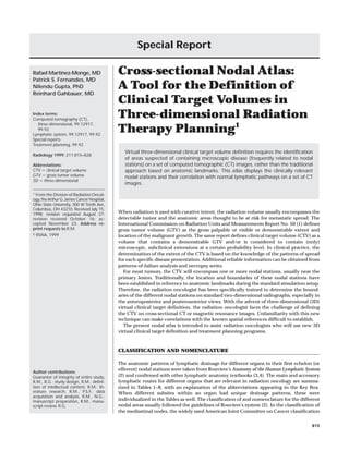
- 1. Special Report Rafael Martinez-Monge, MD Patrick S. Fernandes, MD Nilendu Gupta, PhD Reinhard Gahbauer, MD Index terms: Computed tomography (CT), three-dimensional, 99.12917, 99.92 Lymphatic system, 99.12917, 99.92 Special reports Treatment planning, 99.92 Radiology 1999; 211:815–828 Abbreviations: CTV ϭ clinical target volume GTV ϭ gross tumor volume 3D ϭ three-dimensional Cross-sectional Nodal Atlas: A Tool for the Definition of Clinical Target Volumes in Three-dimensional Radiation Therapy Planning1 Virtual three-dimensional clinical target volume definition requires the identification of areas suspected of containing microscopic disease (frequently related to nodal stations) on a set of computed tomographic (CT) images, rather than the traditional approach based on anatomic landmarks. This atlas displays the clinically relevant nodal stations and their correlation with normal lymphatic pathways on a set of CT images. 1 From the Division of Radiation Oncology, the Arthur G. James Cancer Hospital, Ohio State University, 300 W Tenth Ave, Columbus, OH 43210. Received July 15, 1998; revision requested August 27; revision received October 16; accepted November 23. Address reprint requests to R.M. RSNA, 1999 When radiation is used with curative intent, the radiation volume usually encompasses the detectable tumor and the anatomic areas thought to be at risk for metastatic spread. The International Commission on Radiation Units and Measurements Report No. 50 (1) defines gross tumor volume (GTV) as the gross palpable or visible or demonstrable extent and location of the malignant growth. The same report defines clinical target volume (CTV) as a volume that contains a demonstrable GTV and/or is considered to contain (only) microscopic, subclinical extensions at a certain probability level. In clinical practice, the determination of the extent of the CTV is based on the knowledge of the patterns of spread for each specific disease presentation. Additional reliable information can be obtained from patterns-of-failure analysis and necropsy series. For most tumors, the CTV will encompass one or more nodal stations, usually near the primary lesion. Traditionally, the location and boundaries of these nodal stations have been established in reference to anatomic landmarks during the standard simulation setup. Therefore, the radiation oncologist has been specifically trained to determine the boundaries of the different nodal stations on standard two-dimensional radiographs, especially in the anteroposterior and posteroanterior views. With the advent of three-dimensional (3D) virtual clinical target definition, the radiation oncologist faces the challenge of defining the CTV on cross-sectional CT or magnetic resonance images. Unfamiliarity with this new technique can make correlations with the known spatial references difficult to establish. The present nodal atlas is intended to assist radiation oncologists who will use new 3D virtual clinical target definition and treatment planning programs. CLASSIFICATION AND NOMENCLATURE Author contributions: Guarantor of integrity of entire study, R.M., R.G.; study design, R.M.; definition of intellectual content, R.M.; literature research, R.M., P.S.F.; data acquisition and analysis, R.M., N.G.; manuscript preparation, R.M.; manuscript review, R.G. The anatomic patterns of lymphatic drainage for different organs to their first echelon (or efferent) nodal stations were taken from Rouviere’s Anatomy of the Human Lymphatic System (2) and confirmed with other lymphatic anatomy textbooks (3,4). The main and accessory lymphatic routes for different organs that are relevant in radiation oncology are summarized in Tables 1–8, with an explanation of the abbreviations appearing in the Key Box. When different subsites within an organ had unique drainage patterns, these were individualized in the Tables as well. The classification of and nomenclature for the different nodal areas usually followed the guidelines of Rouviere’s system (2). In the classification of the mediastinal nodes, the widely used American Joint Committee on Cancer classification 815
- 2. Key Box for Abbreviations in Tables and Figures Abbreviation APWN ATL AxN BTL CIN CN CPN DN EIN GL HMN HN HPL IGL IIN IJN IMN IN IPN IRN JVN LCP LGN LPN LRH LUP MN NL PAN PAuN PCL PecN PEN Nodal Group Abbreviation Aortopulmonary window nodes Anterior tongue lymphatics Axillary nodes Base tongue lymphatics Common iliac nodes Celiac axis nodes Cervical pretracheal nodes Diaphragmatic nodes External iliac nodes Glottic lymphatics High mediastinal nodes Hepatic nodes Hard palate lymphatic plexus Infraglottic lymphatics Internal iliac nodes Internal jugular nodes Internal mammary nodes Superficial inguinal nodes, deep inguinal nodes Internal pudendal nodes Inferior rectal nodes Juxtavertebral nodes Left cervical paratracheal nodes Left gastric nodes Left paraaortic nodes Left renal hilum nodes Left upper paratracheal nodes Mastoid nodes Nasopharyngeal lymphatic plexus Preaortic nodes Preauricular nodes Postcricoid lymphatic plexus Pectoral nodes Paraesophageal nodes PFL PG&N PHN PL PLN PPL PRL PSL PsRN PiL PTrN PVgL PVL PVsN RAN RCP RRH RLP RPN RUP SAN ScIN SCN SGL SMaN SMeN SMN SN SPL SplN SRN SVL TL Nodal Group Pyriform fossa lymphatics Parotid gland and nodes Hilar nodes Parametrial lymphatic plexus Prelaryngeal nodes Periprostatic lymphatic plexus Perirectal lymphatic plexus Paranasal sinuses lymphatics Superior posterior pharyngeal wall lymphatics and retropharyngeal nodes Inferior posterior pharyngeal wall lymphatics Mediastinal pretracheal nodes Paravaginal lymphatic plexus Perivesical lymphatic plexus Prevascular nodes Retroaortic nodes Right cervical paratracheal nodes Right hilum renal nodes Right lower paratracheal nodes Right paraaortic nodes Right upper paratracheal nodes Spinal accessory nodes Supraclavicular nodes Subcarinal nodes Supraglottic lymphatic plexus Submandibular nodes Submental nodes Superior mesenteric nodes Sacral nodes Soft palate lymphatics Splenic nodes Superior rectal nodes Seminal vesicles lymphatic plexus Tonsil lymphatic plexus TABLE 1 Head and Neck Lymphatic System (I) was chosen instead (5). The nodal areas represented are listed in the Key Box. When clinically relevant, some nodal stations were further divided into subgroups, which are noted as lowercase letters after the abbreviation codes provided in the Tables and the Figures. The nonparenthesized lowercase letters indicate differentiated subgroups, usually in the direction of the zzЈ axis. Parenthesized letters indicate subgroup subdivision, usually in the direction of the xxЈ axis (shown only for inguinal and external iliac nodes). LOCALIZATION OF NODAL STATIONS The different nodal stations were outlined and labeled on five different sets of consecutive and equidistant CT images (head and neck, thorax, abdomen, male pelvis, and female pelvis) (Figs 1–6). We elected to use CT images because they are the customary image support in most 3D virtual clinical target definition programs. The nodal stations on the crosssectional images were localized by ex816 • Radiology • June 1999 Anatomic Site Lacrimal gland First Echelon Nodal Group Preauricular nodes Parotid nodes Submandibular nodes Eyelids, conjunctiva Preauricular nodes Parotid nodes Submandibular nodes Pinna Preauricular nodes Parotid nodes Mastoid nodes Internal jugular nodes External auditory canal Parotid nodes Internal jugular nodes Middle ear Preauricular nodes Retropharyngeal nodes Internal jugular nodes External nose Submandibular nodes Nasal cavity Retropharyngeal nodes Internal jugular nodes Paranasal sinuses Retropharyngeal nodes Internal jugular nodes Lip, upper Submandibular nodes Submental nodes Preauricular nodes Lip, lower Submandibular nodes Submental nodes Cheek, cutaneous Submandibular nodes Submental nodes Parotid nodes Buccal mucosa Submandibular nodes Tongue, apex Submental nodes Internal jugular nodes Tongue, lateral and posterior Submandibular nodes Internal jugular nodes Subgroup Category Abbreviation Main Main Main Main Main Main Main Main Main Upper Main Main Upper Main Main Main Upper Main Main Main Upper Main Main Upper Main Main Accessory Accessory Main Main Main Main Main Main Main Upper, middle Main Main Upper Main PAuN PG&N SMaN PAuN PG&N SMaN PAuN PG&N MN IJNu PG&N IJNu PAuN PsRN IJNu SMaN PsRN IJNu PsRN IJNu SMaN SMeN PAuN SMaN SMeN SMaN SMeN PG&N SMaN SMeN IJNu, m SMaN IJNu Martinez-Monge et al
- 3. Figure 1. CT images depict head and neck nodal stations at levels hn01 through hn09 on the topogram in Figure 7. Volume 211 • Number 3 Cross-sectional Nodal Atlas for Definition of Clinical Target Volumes • 817
- 4. TABLE 2 Head and Neck Lymphatic System (II) Anatomic Site Floor of mouth Lower gum Upper gum Hard palate, soft palate inferior Soft palate, superior Tonsil Nasopharynx Pyriform fossa Posterior cricoid Posterior pharyngeal wall, superior Posterior pharyngeal wall, inferior Supraglottic larynx Infraglottic larynx Trachea Thyroid Parotid gland Submandibular gland Sublingual gland trapolating information from crosssectional anatomy atlases (6), lymphatic atlases (3), and vascular atlases (4). To allow easy correlation, the five sets of CT images were connected with a recognizable bone structure on a topogram (Fig 7). REPRESENTATION OF THE ANATOMY OF THE LYMPHATIC SYSTEM IN THE NODAL ATLAS The initial lymphatic system is composed of capillary lymphatics, which originate in the intima of the tissue and are immersed in the ground substance of the tissue space. These capillaries anastomose in networks to form the peripheral lym- 818 • Radiology • June 1999 First Echelon Nodal Group Submental nodes Submandibular nodes Internal jugular nodes Submandibular nodes Submental nodes Internal jugular nodes Submandibular nodes Retropharyngeal nodes Internal jugular nodes Submandibular nodes Retropharyngeal nodes Retropharyngeal nodes Internal jugular nodes Internal jugular nodes Retropharyngeal nodes Internal jugular nodes Spinal accessory nodes Internal jugular nodes Internal jugular nodes Retropharyngeal nodes Internal jugular nodes Internal jugular nodes Internal jugular nodes Internal jugular nodes Cervical pretracheal nodes Prelaryngeal nodes Cervical pretracheal nodes Cervical paratracheal nodes Prelaryngeal nodes Cervical pretracheal nodes Cervical paratracheal nodes Internal jugular nodes Retropharyngeal nodes Parotid nodes Submandibular nodes Submandibular nodes Internal jugular nodes Submandibular nodes Internal jugular nodes Subgroup Upper, middle Upper, middle Upper Upper Upper Upper Upper, middle Upper, middle Upper Middle Upper, middle Middle, lower Cervical Cervical Cervical Cervical Cervical Upper, middle, lower Upper Upper Category Abbreviation Main Main Main Main Main Main Main Main Main Accessory Accessory Main Main Main Main Main Main Main Main Main Main Main SMeN SMaN IJNu, m SMaN SMeN IJNu, m SMaN PsRN IJNu SMaN PsRN PsRN IJNu IJNu PsRN IJNu SAN IJNu, m IJNu, m PsRN IJNu IJNm Main Main Main Main Main Main Accessory Main Main Main IJNu, m IJNm, l CPN PLN CPN LCP, RCP PLN CPN LCP, RCP IJNu, m, l Accessory Main Main Main Main Main Main PsRN PG&N SMaN SMaN IJNu SMaN IJNu phatic plexuses. These plexuses are only represented in the atlas for certain organs that are frequently irradiated while intact (prostate, rectum, some head and neck subsites, etc) to facilitate the recognition of the organ or site and its spatial relationship with the surrounding nodal stations. The lymphatic plexuses drain to the first echelon lymph nodal stations through precollecting and collecting ducts. Sometimes, there are intercalating lymph nodes in the path of the collecting ducts. In general, no intermediate paths between the organ of interest and the first echelon nodal station have been represented in the atlas to avoid unnecessary complexity. However, some clinically relevant intercalating nodes have been rep- resented (superior and inferior rectal nodes and internal pudendal nodes). The first nodal station reached by the lymphatic drainage of a given organ is called the first echelon nodal group. The first echelon lymph nodes connect to each other through postlymphonodal collecting ducts and finally drain to more central efferent lymph nodes or directly into the venous system through the main lymphatic trunks, depending on anatomic location. As a rule, the first echelon nodal stations for all the different organs of the head and neck, thorax, abdomen, and pelvis are represented. These are listed in the Tables 1–8. One exception to this rule has been the case of the small bowel and most of the large bowel. Due to the Martinez-Monge et al
- 5. Figure 2. CT images depict head and neck nodal stations at the levels hn10 through hn18 on the topogram in Figure 7. Volume 211 • Number 3 Cross-sectional Nodal Atlas for Definition of Clinical Target Volumes • 819
- 6. TABLE 3 Thoracic Lymphatic System Anatomic Site Lung; RUL anteromedial Lung; RUL posterolateral, RML, RLL superior Lung; RLL inferior Lung; LUL superior Lung; LUL inferior, LLL superior, LLL middle Lung, LLL inferior Costal pleura, superior Costal pleura, middle Costal pleura, inferior Right diaphragm, subperitoneal Left diaphragm, subperitoneal Right and left diaphragm, subpleural Breast anatomic mobility of these organs, the efferent pre- and paraaortic nodal groups (fixed structures with reproducible location), rather than the first echelon nodal groups (juxtaintestinal and paracolic), are represented in the atlas. Patterns of anomalous nodal spread, such as retrograde spread, are not shown in this atlas. ERRORS IN LOCALIZATION OF NODAL STATIONS Lymphography is the technique of choice to visualize nodal groups. However, its decline in the field of diagnostic radiol- 820 • Radiology • June 1999 Category Abbreviation Right paratracheal nodes First Echelon Nodal Group Upper, lower Subgroup Main RUP, RLP Right paratracheal nodes Right hilar nodes Subcarinal nodes Right hilar nodes Subcarinal nodes Left upper paratracheal nodes Prevascular nodes Aortopulmonary window nodes Left upper paratracheal nodes Prevascular nodes Aortopulmonary window nodes Left hilar nodes Subcarinal nodes Left hilar nodes Subcarinal nodes Supraclavicular nodes Internal jugular nodes Juxtavertebral nodes Internal mammary nodes Axillary nodes Juxtavertebral nodes Internal mammary nodes Diaphragmatic nodes Retroaortic nodes Paraesophageal nodes Retroaortic nodes Diaphragmatic nodes Paraesophageal nodes Retroaortic nodes Axillary nodes Internal mammary nodes Supraclavicular nodes Pectoral nodes Upper, lower Main Main Main Main Main Main RUP, RLP PHNr SCN PHNr SCN LUP Main Main PVsN APWN Main Main Main Main Main LUP PVsN APWN PHNl SCN Main Main Main Lower Main Any level Main Any level Main Main Any level Main Any level Main Right lateral Main Suprarenal, thoracic Main Inferior Main Suprarenal, thoracic Main Main Anterior, lateral Main Inferior Main Suprarenal Main Any level Main Accessory Accessory ogy has led to the decline of its use as a tool for radiation therapy planning, and it has been virtually abandoned for both purposes. However, currently used standard radiation ports still follow the boundaries determined during the lymphographic era. During standard simulation, the different nodal stations are not actually seen on the simulation radiographs; therefore, a margin of normal tissue is taken around the CTV to allow for any localization uncertainties. Three-dimensional virtual clinical target definition, like standard simulation, lacks visualization of nodal stations. However, because localization errors on cross-sectional im- PHNl SCN SclN IJNl JVNs, m, i IMNs, m, i AxN JVNs, , m, i IMNs, m, i DNlat RANsr, t PENi RANsr, t DNa, lat PENi RANsr AxN IMNs, m, i SclN PecN ages are minimized (as are the associated increases in CTV uncertainty and size of the planning taget volume), this problem is not as great. During 3D virtual clinical target definition, only a few of the nodal stations represented in the atlas are visible on a CT image. So, the exact location of a given station in an individual is difficult to determine. Furthermore, the internal structure of the lymphatic system (different normal variants among subjects) precludes any categorical statement (2–4). Therefore, we chose to outline wide areas rather than discrete locations for each nodal station to account for the differences in normal anatomic Martinez-Monge et al
- 7. Figure 3. CT images depict the nodal stations in the thorax (th). Volume 211 • Number 3 Cross-sectional Nodal Atlas for Definition of Clinical Target Volumes • 821
- 8. TABLE 4 Gastrointestinal Lymphatic System (I) Anatomic Site First Echelon Nodal Group Gastric cardia Left gastric nodes Gastric lesser cur- Left gastric nodes vature Gastric antrum Hepatic nodes and pylorus Greater omentum Hepatic nodes Gastric greater curvature Duodenum Pancreas Spleen Liver Gallbladder and cystic duct Hepatic duct Common bile duct Splenic nodes Subgroup Category Abbreviation Juxtacardiac Gastropancreatic Lesser curvature Right gastroepiploic Infrapyloric Suprapyloric Right gastroepiploic Infrapyloric Suprapyloric Suprapancreatic Hepatic nodes Main Main Main Main Main Main Main Main Main Main Postpancreaticoduodenal Main Main Main Main Main Main Main Main Main Main Main Main Main Main Main Main Main Main Main Main Main Main Main Main Main Main HNp HNp HNpd SMN HNp HNpd HNha SplNs SplNh LGNlc SMN SMN SMN RPNs LPNs SplNh HNha CN LGNlc DNa, lat PENi RRH, LRH HNha HNha HNha HNha Main Infrapyloric Retropyloric Pancreaticoduodenal Superior mesenteric nodes Postpancreaticoduodenal Hepatic nodes Infrapyloric, suprapyloric Pancreaticoduodenal Hepatic artery Splenic nodes Suprapancreatic Splenic hilum Left gastric nodes Gastropancreatic Superior mesenteric nodes Root of mesentery Middle colic Postpancreaticoduodenal Right paraaortic nodes Superior Left paraaortic nodes Superior Splenic nodes Splenic hilum Hepatic nodes Gallbladder, hepatic artery Celiac axis nodes Left gastric nodes Lesser curvature Diaphragmatic nodes Anterior, lateral Paraesophageal nodes Inferior Renal hilum nodes Hepatic nodes Gallbladder Foramen of Winslow Hepatic nodes Foramen of Winslow Hepatic nodes Foramen of Winslow LGNc LGNlc LGNlc HNrg HNp HNp HNrg HNp HNp SplNs HNpd TABLE 5 Gastrointestinal Lymphatic System (II) Anatomic Site Jejunum, ileum Cecum and appendix Ascending colon Transverse colon, right Transverse colon, left Descending colon Sigmoid colon Rectum Efferent Nodal Group* Subgroup Superior mesenteric nodes Superior mesenteric nodes Superior mesenteric nodes Superior mesenteric nodes Superior mesenteric nodes Left paraaortic nodes Any level Category Abbreviation Main Main Main Main Main Main SMN SMN SMN SMN SMN LPNsr, s, m, i, LRH Superior mesenteric nodes Main SMN Preaortic nodes Inferior mesenteric Main PANs, m Left paraaortic nodes Superior, middle Main LPNs, m Preaortic nodes Inferior mesenteric Main PANs, m Internal iliac nodes Accessory IIN Sacral nodes Accessory SN * In the small and large intestine, the first echelon nodal group is represented by the juxtaintestinal (small-bowel) or paracolic (large-bowel) nodes located in the mesenteric border of the organ. Because of the mobility of these organs, the efferent nodal groups (fixed structures with reproducible location), rather than the first echelon nodal groups, are represented in the atlas. 822 • Radiology • June 1999 Martinez-Monge et al
- 9. Figure 4. CT images depict the nodal stations in the abdomen (ab). variability and nodal interconnection. Another difficult problem is the mobility of the nodal stations located proximally in the limbs (inguinal, axilla). The location of these nodal groups will vary greatly, depending on simulation positioning. The cross-sectional images provided in this atlas were taken during standard CT positioning and may differ from images taken for radiation planning in special positions. The topograms with bone landmarks may help in correlating the cross sections provided in this atlas with the reference points of the actual patients. Volume 211 • Number 3 SYSTEMATIC VERSUS NONSYSTEMATIC DESCRIPTION This atlas is strongly biased toward the radiation oncology standpoint. Some nodal areas have been arbitrarily discarded because they are rarely relevant in radiation oncology. We elected to ignore the distal and intermediate nodal stations of the extremities and the nodal stations of muscular groups. Tumors that spread to these nodal stations represent a very small percentage of the overall clinical practice in radiation oncology. We also chose not to represent lymph nodal stations pertaining to mobile structures (mesenteric nodes of the small bowel and most of the large bowel) because of spatial unpredictability. For these anatomic locations, only the efferent pre- and paraaortic nodal groups have been represented. ATLAS LIMITATIONS This atlas cannot be used as a tool to diagnose or predict nodal involvement. It Cross-sectional Nodal Atlas for Definition of Clinical Target Volumes • 823
- 10. only provides a guide to the general anatomic pathways of nodal drainage of the normal organs shown. It cannot help forecast individual spread patterns. When used for 3D virtual clinical target definition, this nodal atlas can help in accurately defining the location of the different nodal stations that are to be included in the CTV. Deciding which nodal stations should be included in the CTV depends on the level of spread probability that is clinically assumable for that specific disease manifestation and the normal tissue complication probability for that intended dose level. These two issues are a matter of clinical judgment that is beyond the general purpose of this atlas. POTENTIAL ADVANTAGES A nodal atlas allows systematic definition of CTVs in those clinical situations in which the irradiation of nodal areas is clinically relevant, which may facilitate reliable intercommunication among institutions. The current tendency, however, is to define CTVs on a nonanatomic basis, probably due to the lack of a common anatomic language. Some ongoing radiation therapy protocols have elected to define the corresponding CTVs as a volume around the GTV. The CTV is then defined mathematically as a margin around the GTV. Although reproducible among institutions, this definition carries the important risk of including in the CTV some areas with a minimal probability of tumor involvement or areas that may be at higher risk for treatment toxicity. A nodal atlas allows a better spatial understanding of the valuable information contained in the surgical pathology reports. For those patients undergoing postoperative radiation therapy, the decision-making process essentially depends on the surgical findings. Improving the ability to locate high-risk areas (as defined by the surgical information) on a cross-sectional image must necessarily improve the quality in treatment planning and delivery. We are currently evaluating the potential for redesigning radiation plans on the basis of nodal information from surgical series and 3D reconstruction with the aid of this atlas. 824 • Radiology • June 1999 TABLE 6 Lymphatic System of the Urinary Tract Anatomic Site First Echelon Nodal Group Right perirenal tissue Left perirenal tissue Right kidney Interaortic nodes Preaortic nodes Left paraaortic nodes Preaortic nodes Right renal hilum nodes Retroaortic nodes Left kidney Left renal hilum nodes Left paraaortic nodes Suprarenal glands Renal hilum nodes Paraaortic nodes Juxtavertebral nodes Paraesophageal nodes Ureter, superior Paraaortic nodes segment Common iliac nodes External iliac nodes Ureter, middle Paraaortic nodes segment Common iliac nodes Ureter, inferior Common iliac nodes segment External iliac nodes Internal iliac nodes Bladder External iliac nodes Internal iliac nodes Common iliac nodes Bulbomembranous External iliac nodes urethra Subgroup Category Superior Superior Superior Superior Main Accessory Main Accessory Main Superior Main Main Superior Main Main Suprarenal Main Inferior Accessory Inferior Accessory Superior Main Accessory Any level (central, medial) Accessory Middle Main Main Main Any level (central, medial) Main Main Any level (central, medial) Main Accessory Accessory Middle, inferior (medial) Main Abbreviation RANs PANs LPNs PANs RRH RANs LRH LPNs RRH, LRH LPNsr, RPNsr JVNi PENi RPNs, LPNs CIN EINs, m, i(c, m) RPNm, LPNm CIN CIN EINs, m, i(c, m) IIN EINs, m, i(c, m) IIN CIN EINm, i(m) TABLE 7 Lymphatic System of the Male Genital Organs Anatomic Site Scrotum Perineum Penis, skin Penis, glans Penis, corpora cavernosa/penile urethra Right testicle/epididymis First Echelon Nodal Group Any level Inferior (medial) Superior (medial) Superior (medial) Right paraaortic nodes Superior, middle, inferior Superior, middle, inferior Any level (central) Preaortic nodes Left testicle/epididymis External iliac nodes Left renal hilum nodes Left paraortic nodes Preaortic nodes Ductus deferens External iliac nodes External iliac nodes Seminal vesicles Internal iliac nodes External iliac nodes Prostate/prostatic urethra Subgroup Superficial inguinal nodes Superficial inguinal nodes Superficial inguinal nodes Superficial inguinal nodes Deep inguinal nodes External iliac nodes Internal iliac nodes Superficial inguinal nodes Internal iliac nodes External iliac nodes Internal iliac nodes Sacral nodes Inferior (medial) Superior (medial) Superior Superior, middle, inferior Any level (central) Superior, middle (central), inferior (central, lateral) Any level (medial, central) Any level (central) Category Abbreviation Main Main Main Main Main Accessory Accessory Main INs, i(m, l) INi(m) INs(m) INs(m) INs, i(d) EINi(m) IIN INs(m) Main RPNs, m, i Main PANs, m, i Accessory Main Main Accessory EINs, m, i(c) LRH LPNs PANs, m, i Accessory EINs, m, i(c) Main EINs, m(c), i(c, l) Main Main IIN EINs, m, i(m, c) Main Main IIN EINs, m, i(c) Main Main IIN SN Martinez-Monge et al
- 11. Figure 5. CT images depict the nodal stations in the male pelvis (mp). Volume 211 • Number 3 Cross-sectional Nodal Atlas for Definition of Clinical Target Volumes • 825
- 12. Figure 6. CT images depict the nodal stations in the female pelvis (fp). 826 • Radiology • June 1999 Martinez-Monge et al
- 13. Figure 7. Topograms show the levels to which the CT images in Figures 1–6 correspond. Volume 211 • Number 3 Cross-sectional Nodal Atlas for Definition of Clinical Target Volumes • 827
- 14. TABLE 8 Gynecologic Lymphatic System Anatomic Site Right ovary First Echelon Nodal Group Right paraaortic nodes External iliac nodes Left renal hilum Left paraaortic nodes Preaortic nodes External iliac nodes Right fallopian tube Right paraaortic nodes External iliac nodes Internal iliac nodes Left fallopian tube Left paraaortic nodes External iliac chain Internal iliac nodes Cervix uteri External iliac nodes Subgroup Superior, middle, inferior Superior (central) Left ovary Corpus uteri Vagina Vulva Clitoris Greater vestibular glands Internal iliac nodes Sacral nodes Right paraaortic nodes Preaortic nodes Left paraaortic nodes External iliac nodes Superficial inguinal nodes External iliac nodes Internal iliac nodes Sacral nodes Superficial inguinal nodes Superficial inguinal nodes Deep inguinal nodes Superficial inguinal nodes Finally, the atlas-based 3D definition of CTVs has the potential to improve the 828 • Radiology • June 1999 Superior Superior Any level (central) Inferior Superior (central) Superior Superior (central) Superior, middle (medial, central) Inferior Middle Middle Superior (central) Superior (medial) Any level (central, medial) Superior (medial) Any level Superior (medial) Category Abbreviation Main RPNs, m, i Accessory Main Main Main Accessory Main Accessory Accessory Main Accessory Accessory Main EINs(c) LRH LPNs PANs EINs, m, i(c) RPNi EINs(c) IIN LPNs EINs(c) IIN EINs, m(m, c) Main Main Main Main Main Accessory Accessory Main IIN SN RPNi PANm LPNm EINs(c) INs(m) EINs, m, i(c, m) Main Accessory Main Main Main Main IIN SN INs(m) INs, i(m, l) INs, i(d) INs(m) therapeutic ratio. Nodal groups with a very low probability of metastatic involve- ment can be excluded from the CTV, thus expanding beam arrangement possibilities and allowing increased treatment intensity. We are also currently evaluating the volumetric implications (normal tissue dose-volume histograms) of using 3D virtual simulation with either a nodal atlas or standard bone landmarks. The present atlas should aid the radiation oncologist in accurately locating on cross-sectional images the different nodal stations that will correspond to the chosen clinical target volume. Acknowledgments: The authors thank John Croyle for his help in the preparation of the graphic matrix of the illustrations and David Carpenter for editorial assistance. References 1. International Commission on Radiation Units and Measurements. Prescribing, recording and reporting photon beam therapy. ICRU Report 50. Washington, DC: International Commission on Radiation Units and Measurements, 1993. 2. Rouviere H. Anatomy of the human lymphatic system. Ann Arbor, Mich: Edwards, 1938. 3. Donini I, Battezatti M. The lymphatic system. Padua, Italy and London, England: Piccin Medical Books, 1972. 4. Uflacker R. Atlas of vascular anatomy. Baltimore, Md: Williams & Wilkins, 1997. 5. American Joint Committee on Cancer. AJCC cancer staging manual. 5th ed. Philadelphia, Pa: Lippincott-Raven, 1997. 6. Ellis H, Logan B, Dixon A. Human cross sectional anatomy. Oxford, England: Butterworth-Heinemann, 1991. Martinez-Monge et al