3. AUTOMATIC TRANSMISSION SERVICE GROUP
Technical Service Information
3
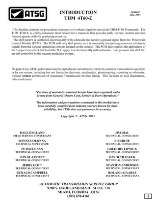
THM 4T60-E COMPONENT APPLICATION CHART
INPUT
CLUTCH
ON
ON ON ON
ON
OFF
OFF
OFF
OFF
OFF
OFF OFF
OFF
ON
ON 2.92
2.92
2.92
2.92
2.38
1.56
1.56
1.56
1.00
1.00
0.70
ON
ON
ON
ON
ON
ON
ON
ON
ON
ON
ON
ON
Hold Hold
Hold
Hold
Hold
Hold
Hold
Hold
Hold
Hold
Hold
O/R
O/R
O/R
O/R
O/R
O/R
Hold
Hold
Hold
ON
ON
ON
ON
ON
ON
ON ON
ON
ON
ON
ON
ON
ON ON
ON ON
ON
ON
ON
ONON
ON
ON
ON
ON
ON
ON
ON
ON
ON
ON
Park/Neut
D4-1st
D3-1st
D2-1st
LO-1st
Reverse
D2-2nd
D3-2nd
D3-3rd
D4-2nd
D4-3rd
D4-4th
2ND
CLUTCH
3RD
CLUTCH
4TH
CLUTCH
FORWARD
BAND
REVERSE
BAND
INPUT
SPRAG
1-2
ROLR
3RD
ROLR
SOLND
"A"
SOLND
"B"
GEAR
RATIO
D-2
BAND
Fourth
Clutch
Second
Clutch
Input
Clutch
Third
Clutch
3rd Roller
Clutch Or Sprag
1-2 Roller
Clutch
Input
Sprag
Reverse
Band
Forward
Band
2-1 Manual
Band
Figure 1
4. - Park position enables the engine to be started while
preventing the vehicle from rolling either forward or
backward. For safety reasons, the vehicle's parking brake
should be used in addition to the transaxle "Park" position.
Since the final drive differential and output shaft are
mechanically locked to the case through the parking pawl
and final drive ring gear, "Park" position should not be
selecteduntilthevehiclehascometoacompletestop.
- Reverse enables the vehicle to be operated in a
rearwarddirection.
- Neutral position enables the engine to start and
operate without driving the vehicle. If necessary, this
position should be selected to restart the engine while the
vehicleismovingforward.
- Overdrive position should be used for all normal
driving conditions for maximum efficiency and fuel
economy. Overdrive range allows the transaxle to operate
in each of the four forward gear ratios. Downshifts to a
lower gear, are available for safe passing by pressing the
accelerator, or by manually selecting a lower gear with the
selector lever.
The transaxle should not be operated in Overdrive when
towing a trailer or driving in mountainous terrain. Under
these conditions, that put an extra load on the engine, the
transaxle should be driven in a lower manual gear selection
for maximum efficiency.
- Manual 3rd can be selected for conditions where it
may be desirable to use only three forward gear ratios.
These conditions include towing a trailer and driving on
hilly terrain as described above. This range is also helpful
for engine braking when descending slight grades.
Upshifts and downshifts are the same as in Overdrive
range for 1st, 2nd and 3rd gears, but the transaxle will not
shift into 4th gear.
- Manual 2nd adds more performance for congested
traffic and hilly terrain. The transaxle still starts out in 1st
gear, but this position prevents the transaxle from shifting
above 2nd gear. Manual 2 can also be selected to retain
2nd gear for acceleration and/or engine braking as desired.
Manual 2 can be selected at any vehicle speed. If transaxle
is in 3rd or 4th gear when Manual 2 is selected, it will
immediately shift to 2nd gear.
- Manual 1st can be selected at any vehicle speed. If the
transaxle is in 3rd or 4th gear it will immediately shift into
2nd gear. When vehicle speed slows to below
approximately 35mph, the transaxle will then downshift
into 1st gear. This is beneficial for maintaining maximum
enginebrakingwhendescendingsteepgrades.
AUTOMATIC TRANSMISSION SERVICE GROUP
Technical Service Information
4
GENERAL DESCRIPTION
EXPLANATION OF GEAR RANGES
The THM 4T60-E is a fully automatic 4 speed front wheel drive
transaxle. It consists primarily of a four element torque
converter, two planetary gear sets, various multi-disc clutches, a
differentialassembly,andacontrolvalvebody.
The four element torque converter contains a pump, a turbine, a
pressure plate splined to the turbine, and a stator assembly. The
torque converter acts as a fluid coupling to smoothly transmit
power from the engine to the transaxle. It also hydraulically
provides additional torque multiplication when required. The
pressure plate, when applied, provides a mechanical "direct
drive"couplingoftheenginetothetransaxle.
The two planetary gear sets provide the four forward gear ratios
and reverse. Changing of the gear ratios is fully automatic and is
accomplished through the use of various electronic engine
sensors that provide input signals to the Powertrain Control
Module (PCM). The PCM interprets these signals to control
current to the various shift solenoids, converter clutch solenoids,
orswitchesinsidethetransaxle,asshowninFigure2.
By using electronics, the PCM controls shift points and torque
converter apply and release, to provide proper gear ranges for
maximumfueleconomyandvehicleperformance.
Four multiple-disc clutches, two sprags, a roller clutch, and three
bands provide the friction elements required to obtain the
variousgearratioswiththeplanetarygearsets.
A hydraulic system which consists of the control valve body,
pressurized by a vane type pump, provides the working pressure
neededtooperatethefrictionelementsandautomaticcontrols.
Several electronic switches, solenoids and sensors, as shown in
Figure 2, are working in conjunction with the vehicles PCM or
Electronic Control Module (ECM), control various shift points
andtheapplyandreleaseoftheconverterclutch.
P R N D D 2 1
The transaxle can be operated in any one of the seven
differentpositionsshownbelowontheshiftquadrant.
P
R
N
D
2
1
D
5. AUTOMATIC TRANSMISSION SERVICE GROUP
Technical Service Information
5
ELECTRICAL COMPONENTS
The THM 4T60-E transaxle incorporates electronic controls that
utilizes the Powertrain Control Module (PCM) to command shift
points and, TCC apply and release. Electrical signals from
numerous sensors provides information to the PCM about
vehicle speed, throttle position, engine coolant temperature, gear
range selection and braking. The PCM uses this information to
determine the precise moment to energize or de-energize various
solenoids located inside the transaxle. Accordingly, the
transaxle is enabled to shift into the appropriate gear and apply or
release the torque converter. This type of control provides for
consistantandpreciseshiftpointsformaximumeffeciency.
If for any reason the entire electronic control system to the
transaxle becomes disabled, both shift solenoids will be off,
which is failsafe mode. This operating state of the solenoids
permits the transaxle to operate in 3rd gear providing the gear
selectorleverisintheOverdriveorD3Range.
However, if the gear selector lever is moved to the D2 or D1
range, with both solenoids disabeled, the transaxle will operate
in 2nd gear. The purpose for this is to allow the transaxle to
hydraulically function in these two ranges despite the disabled
electronicsystem.
Another feature of the THM 4T60-E is the manual hydraulic
override of the electronic control system. When D3 or D2 range
is selected, the 3-4 shift valve or the 2-3 shift valve is
hydraulically forced to move. The transaxle can now be
operated in the selected gear range, regardless of the state of the
shiftsolenoids.
When D1 (Manaul 1st) is selected however, the gear selection is
completely electronic for safety, durability and pleaseability
concerns. This means that the PCM must electronically
command the solenoids to be in 1st gear, for Manual 1st gear
operationtobeachieved.
Figure 2
6. AUTOMATIC TRANSMISSION SERVICE GROUP
Technical Service Information
6
COIL ASM.
PWM FLUID
FEED
CONNECTOR
EXH
METERING BALLPWM
FLUID
EXHAUST
CONNECTOR
COIL ASM.
FLUID
FEED
TCC/PWM Solenoid
Shift "A", "B" & TCC Solenoids
ON/OFF (Normally Open)
Shift Controls
Shift Solenoid "A"
Shift Solenoid "B"
TCC CONTROLS
TCC (ON/OFF) Solenoid
TCC (PWM) Solenoid
ELECTRICAL COMPONENTS (Cont'd)
The THM 4T60-E uses two ON/OFF (Normally Open) shift
solenoids with a two port design that provides for all forward
gear ranges. These shift solenoids work together in a
combination of ON or OFF sequences to direct fluid pressures to
the various shift valves and thus apply components. The
component chart in Figure 1 shows the solenoid state for each
gear range.
The PCM controls the ground signal for shift solenoid "A" to
control the solenoid ON or OFF, according to transaxle and
vehicle operation. When the solenoid is OFF, filtered line
pressure to the solenoid is exhausted (See Figure 3). When
energized (ON), the exhaust port is blocked, stopping the
exhaust of line pressure through the solenoid. Pressure on the
end of the 1-2 shift valve moves the valve against spring force,
sending line presure into the solenoid "A" passage to the 3-4 shift
valve.
The PCM controls the ground signal for shift solenoid "B" to
control the solenoid ON or OFF, according to transaxle and
vehicle operation. When the solenoid is OFF, filtered line
pressure to the solenoid is exhausted (See Figure 3). When
energized (ON), the exhaust port is blocked, stopping the
exhaust of line pressure through the solenoid, and directing it
into the solenoid "B" passage. Solenoid "B" fluid pressure is
then fed to the 4-3 manual downshift valve and the 3-2 manual
downshift valve.
Most THM 4T60-E transaxles use two solenoids to control the
apply and release of the TCC. The 1st solenoid is the pressure
controlling solenoid (See Figure 4). It is a Pulse Width
Modulated (PWM) solenoid that acts on the converter clutch
regulator valve.
The 2nd solenoid is an ON/OFF solenoid and identical to the two
shift solenoids, as shown in Figure 3.
The PCM controls the ground signal for solenoid to control the
solenoid ON or OFF, according to transaxle and vehicle
operation. The only difference in operation is the ignition
voltage is supplied through the normally closed brake switch to
theTCCsolenoid,onmostmodels.
When the solenoid is OFF, and if the transaxle is operating in 2nd
(some models), 3rd or 4th gear, TCC signal fluid is exhausted
through the solenoid (See Figure 3). When energized (ON), the
exhaust port is blocked, sending TCC signal fluid pressure to
move the converter clutch valve against spring force and line
pressure at the opposite end of the valve.
The PCM controls the TCC/PWM solenoid by varying its
operating duty cycle (ON/OFF time) from 0% to 100%. Until
the transaxle is operating in 2nd (some models) or 3rd gear, the
PWM solenoid is OFF. In this state, filtered PWM feed pressure
flows at maximum pressure through the solenoid and into the
PWM passage (See Figure 4).
When the solenoid is energized, it operates at 32 Hz and from 0%
to 100% duty cycle, depending on vehicle operation. The PWM
solenoid is enabled to modulate the amount of PWM feed
pressure passing through the solenoid and sending it to the
converter clutch regulator valve. At 0% duty cycle, the TCC will
apply at maximum capacity while 100% duty cycle applies it at
minimum capacity.
Figure 3
Figure 4
8. AUTOMATIC TRANSMISSION SERVICE GROUP
Technical Service Information
8
Throttle Position Sensor (TPS)
Coolant Temperature Sensor (CTS)
Park/Neutral Switch
Brake Switch
Engine Speed
Cruise Control
ELECTRICAL COMPONENTS (Cont'd)
The PCM monitors the variable voltage input signal from this
sensor to calculate throttle position or angle. These input signals
are then used by the PCM to determine the appropriate shift
schedule for the transaxle and TCC apply and release.
The Coolant Temperature Sensor (CTS) provides variable
resistance information to the PCM to determine engine coolant
temperature. When the engine is cold, resistance will be high,
and when the engine is hot, resistance through the sensor will be
low. The PCM measures this resistance and will not command
TCC apply until the engine coolant temperature is appropriate
for the particular calibration.
The Park/Neutral Switch, or PRNDL Switch, mounted on the
transaxle manual shaft, provides the gear range selected
information to the PCM. This information also allows the
engine to be started in only Park or Neutral.
On some models, the Brake Switch controls the TCC and cruise
control operation by opening the circuit to disengage the TCC
solenoid from the power feed source when the brake pedal is
depressed. On some models, the brake switch is simply an
ON/OFF discreet input to the PCM.
Monitored by the PCM through the ignition module and is used
to determine wide open throttle shift patterns and TCC apply and
release.
When this device is in operation, it provides a smooth pattern by
requiring a time limit to be met during a 3-2 or 2-3 shift, and a 4-3
or 3-4 shift.
Ohms Resistance Chart
Component
Shift Solenoid "A"
Shift Solenoid "B"
TCC ON/OFF Solenoid
TCC PWM Solenoid
Vehicle Speed Sensor
TFT Sensor
Resistance @ 68°F
20-30 Ohms
20-30 Ohms
20-30 Ohms
10-15 Ohms
981-1864 Ohms
See Charts Below
SENSORRESISTANCE
CHANNEL PLATE TEMPERATURE SENSOR
RESISTANCE VS. TEMPERATURE
TEMPERATURE °C
-40 -30 -20 -10 0 10 20 30 40 50 60 70 80 90 100 110 120 130 140 150
189.3
240.6
309.3
402.6
530.9
710.2
964.7
1331
1870
2676
3911
5844
8935
14006
22571
37498
64305
114023
209812
402382
SENSORRESISTANCE
SPACER PLATE TEMPERATURE SENSOR
RESISTANCE VS. TEMPERATURE
TEMPERATURE °C
-40 -30 -20 -10 0 10 20 30 40 50 60 70 80 90 100 110 120 130 140 150
47.20
59.80
76.80
99.90
132
177
241
332
467
667
973
1459
2237
3515
5671
9423
16176
28677
52684
100707
Figure 7
9. AUTOMATIC TRANSMISSION SERVICE GROUP
Technical Service Information
9
Figure 8
AB
C D
E
FG
AB
C D
E
FG
TEMP SENSOR
BRACKET
10. AUTOMATIC TRANSMISSION SERVICE GROUP
Technical Service Information
10
1991-1995 WIRE SCHEMATICS
1991-1993
1991-1993
1991-1993
1994-1995
1994-1995
1994-1995
Figure 9
Note the difference in the
Pin Functions
for the 1994-Up Models
AB
C D
E
FG
AB
C D
E
FG
AB
C D
E
FG
MODELS CMW
11. AUTOMATIC TRANSMISSION SERVICE GROUP
Technical Service Information
11
AB
C D
E
FG
AB
C D
E
FG
AB
C D
E
FG
Ohms Resistance Chart
Component
Shift Solenoid "A"
Shift Solenoid "B"
TCC ON/OFF Solenoid
TCC PWM Solenoid
Vehicle Speed Sensor
TFT Sensor
Resistance @ 68°F
20-30 Ohms
20-30 Ohms
20-30 Ohms
10-15 Ohms
981-1864 Ohms
See Charts Page 8
CAUTION - - CAUTION - - CAUTION
The addition of the temperature sensor in the 1994
model 4T60-E transaxles required that the pin
functions be completely re-assigned. Since the
temperature sensor required 2 pins on the 7 way
electrical connector and only one was available, it
became necessary to combine the 12 volt power
source to 1 pin, instead of the prior 2 pins.
The wiring schematics provided in Figures 9 and 10
reflect these changes, and this makes the internal
wire harness Non-interchangeable.
Extra care is needed when checking the resistance
through the external case connector, to ensure that
you are on the proper pin cavities.
Example:
Notice in Figure 9 that Pin "A", for the 1991-1993
models, carries the 12 Volts from the brake switch in
to the TCC Apply Solenoid.
Notice also in Figure 9 that Pin "A", for the 1994-
1995 models, carries the ground signal from the
PCM in to Shift Solenoid "A".
Lets assume that you want to check resistance for
Shift Solenoid "A".
On 1991-1993 models you would use pin cavities
"E" and "F".
On 1994-1995 models you would use pin cavities
"E" and "A".
INTERNAL WIRE SCHEMATICS
Figure 10
1996 MODELS
1996 MODELS
1996 MODELS
15. AUTOMATIC TRANSMISSION SERVICE GROUP
Technical Service Information
15
THM 4T60-E LINE PRESSURE CHART
P.S.I.
@ 18 In. Vac.
74-95
165-205
255-315
165-205
74-95
158-170
RANGE
P, R, N, @ 1250 RPM
D1, @ 1250 RPM
D4, D3, D2, @ 1250 RPM
P.S.I.
@ 0 In. Vac.
Hydra-matic
Hydra-matic
Hydra-matic
Hydra-matic
24200113
24200113
24200113
24200113GMPT-B730
GMPT-B730
GMPT-B730
GMPT-B730
6
6
6
2
A
A
D A
D
X
X
W
W
1
1
4 22
MAD
E IN
U.S
.A.
226
lllll ll ll ll ll ll
l
l
l
l
l
l
l
l
l
l
l
l
l
l
l
l
l
l
l
l
l
l
l
l
ll
ll
llll ll
LINE PRESSURE TEST
Minimum Line Pressure Maximum Line Pressure
Special Note:
1. Disconnect and plug the vacuum supply line at
thevacuummodulator.
2. Install vacuum pump to modulator and apply
18 Inches of vacuum to the modulator.
3. Set parking brake, apply foot brake, start engine
and record pressure readings in all gear ranges,
with engine running at the proper RPM.
4. Compare recorded pressure readings with the
informationprovidedinchartbelow.
1. Disconnect and plug the vacuum supply line at
thevacuummodulator.
2. For the maximum line pressure test we want
0 Inches of vacuum to the modulator.
3. Set parking brake, apply foot brake, start engine
and record pressure readings in all gear ranges,
with engine running at the proper RPM.
4. Compare recorded pressure readings with the
informationprovidedinchartbelow.
Line pressure is boosted by manual valve position Only in the D1 position on this transaxle. All other manual
lever positions rely on vacuum drop to raise line pressure.
Line pressure should increase instantly with throttle opening due to a decrease in vacuum supply to the vacuum
modulator. After the tests above have been performed, the vacuum line should be reconnected to the vacuum
modulator and verify that line pressure increases with throttle opening using the vehicles vacuum supply line. If
pressure does not respond properly, it is usually due to carbon build up at the supply line where it enters the
intake manifold, or an exhaust system restriction.
Figure 16
VACUUM PUMP
350 POUND LINE
PRESSURE GUAGE
16. AUTOMATIC TRANSMISSION SERVICE GROUP
Technical Service Information
16
THM 4T60-E OIL PUMP PASSAGES "FRONT SIDE"
THM 4T60-E OIL PUMP PASSAGES "REAR SIDE"
Figure 17
Figure 18
17. AUTOMATIC TRANSMISSION SERVICE GROUP
Technical Service Information
17
THM 4T60-E OIL PUMP COVER PASSAGES
THM 4T60-E TURBINE AND PUMP DRIVE SHAFT PASSAGES
Figure 19
Figure 20
18. AUTOMATIC TRANSMISSION SERVICE GROUP
Technical Service Information
18
THM 4T60-E VALVE BODY PASSAGES "PUMP SIDE"
Figure 21
19. AUTOMATIC TRANSMISSION SERVICE GROUP
Technical Service Information
19
THM 4T60-E VALVE BODY PASSAGES "SPACER PLATE SIDE"
Figure 22
21. AUTOMATIC TRANSMISSION SERVICE GROUP
Technical Service Information
21
THERMOSTATIC
ELEMENT
LOCATED ON
SPACER PLATE
THERMOSTATIC
ELEMENT
LOCATED ON
BOTTOM CASE
THERMOSTATIC
ELEMENT PLATE
FLUID COLD FLUID HOT
FLUID HOT 32°C (90°F)FLUID HOT 18°C (0°F)
THERMOSTATIC ELEMENTS
The THM 4T60-E transaxle utilizes two types of thermostatic elements to control
fluid flow to various components inside the transaxle. These thermostatic
elements contain temperature sensitive bi-metal strips that react to fluid
temperature changes and open or close a fluid passage.
This thermostatic element is located on the valve body spacer plate assembly and
is designed to control, through an orifice, D4 fluid pressure that feeds the forward
servo apply passage. Forward servo apply fluid is then routed to the forward servo
assembly to apply the forward band.
The position of this thermo element varies from a fully open position when fluid
temperature is at 18°C (0°F) to a fully closed position at 32°C (90°F). At low
temperatures, the thermo element is fully open to provide a large feed orifice for
D4 fluid to enter the drive servo apply circuit. As the fluid warms up and flows
easier, the thermo element begins to close and restrict the feed orifice. When the
fluid is warm, the thermo element is fully closed forcing D4 fluid through a single
orifice to stroke the forward band servo assembly.
This thermostatic element is located on the case and is designed to control the fluid
level in the case side cover pan. At low temperatures, the thermostatic element
exerts very little pressure on the thermo element plate allowing fluid to drain into
the sump. As the temperature of the fluid increases, the thermo element begins to
apply pressure to the thermo element plate, thereby trapping fluid in the case side
cover pan. This level of transaxle fluid is necessary in order to maintain the
operation of the hydraulic system.
It should be noted that when checking fluid level in a THM 4T60-E transaxle, it
will be higher on the fluid level indicator when the fluid is cold. Conversely, the
fluid level will drop when checked at operating temperatures. This event is a
result of the thermostatic element functioning as explained.
Forward Servo Thermo Element
Case Thermo Element
Figure 24
22. AUTOMATIC TRANSMISSION SERVICE GROUP
Technical Service Information
22
THM 4T60-E CHANNEL PLATE PASSAGES "VALVE BODY SIDE"
Figure 25
27. AUTOMATIC TRANSMISSION SERVICE GROUP
Technical Service Information
27
THM 4T60-E DRIVEN SPROCKET SUPPORT PASSAGES
Figure 31
Figure 32
Input Clutch Feed
Third Clutch Feed
28. AUTOMATIC TRANSMISSION SERVICE GROUP
Technical Service Information
28
TRANSAXLE DISASSEMBLY
External Components
1. Clean the transaxle exterior thoroughly before
beginninganyofthedisassemblyprocess.
2. Ensure the work area is adequate andclean
for the layout and inspection of components.
3. Remove the torque converter assembly from
the transaxle, as shown in Figure 33.
4. Install a suitable fixture on the transaxle so it
can be rotated in a bench fixture, such as the
oneshown inFigure34.
5. Rotate the transaxle with the extension housing
facingdownwardtoallowfluiddrainage.
6. Remove the "O" ring from the turbine shaft
using a small screwdriver (See Figure 34).
7. Remove the vacuum modulator retaining bolt
and bracket, as shown in Figure 35.
8. Remove and discard the vacuum modulator.
9. Remove the modulator valve from the transaxle
case bore using a magnet (See Figure 35).
10. Remove output speed sensor from extension
housing,asshown inFigure36.
11.Usingthesupportfixtureasapivotpoint,push
thereverseservocoverdownwiththelarge
screwdriverandremovethesnapringusinga
smallerscrewdriver,asshowninFigure37.
Caution: The reverse servo is under pressure.
12. Revove the reverse servo cover "O" ring by
pulling it out and cutting it with sidecutters, as
shown inFigure38.
13.Revovethereverseservoassemblyfromcase
asshown inFigure39.
Figure 33
Figure 34 Figure 35
Continued on Page 30.
29. AUTOMATIC TRANSMISSION SERVICE GROUP
Technical Service Information
29
OUTPUT
SPEED
SENSOR
REVERSE SERVO COVER
REVERSE SERVO
RETURN SPRING
REVERSE SERVO
PISTON ASSEMBLY
SERVO COVER "O" RING
SERVO COVER SNAP RING
Figure 36
Figure 37
Figure 38
Figure 39
30. AUTOMATIC TRANSMISSION SERVICE GROUP
Technical Service Information
30
TRANSAXLE DISASSEMBLY (Cont'd)
External Components (Cont'd)
14. Using an 8mm socket attached to the speed
handle, loosen the forward servo cover bolts,
asshown inFigure40.
Note: Loosen only, servo is under pressure.
15. Apply pressure to the servo cover using the
snap-ring screwdriver with its end against the
edge of bench, as shown in Figure 41.
16. With pressure applied, use your free hand to
completely remove the bolts, and slowly relieve
the pressure and remove the forward servo
assembly (SeeFigure41).
Figure 41
Figure 40
Figure 42
12 FORWARD SERVO COVER BOLTS (3)
31. AUTOMATIC TRANSMISSION SERVICE GROUP
Technical Service Information
31
Figure 43 Figure 44
TRANSAXLE DISASSEMBLY (Cont'd)
Bottom Pan Components
1. Remove the 20 bottom pan bolts and remove
bottom pan, as shown in Figure 42.
2. Remove and discard bottom pan gasket, as
shown inFigure42.
3. Remove and discard the bottom pan filter, as
shown inFigure42.
4. Remove the oil scoop scavenger using a 13mm
socket on speed handle (See Figure 42).
5. Remove only the four accumulator assembly
bolts that are shown in Figure 43, item 131.
6. Remove the three 2-1 manual servo cover bolts
asshown inFigure43.
7. Pry out the final drive lube pipe retaining clip,
asshown inFigure43.
8. Remove the complete accumulator housing,
feed pipes and 2-1 manual servo cover as an
assembly, as shown in Figure 44, and set aside
forcomponentrebuild.
9. Remove the 2-1 manual servo assembly, as
shown in Figure 44, and set aside for the
componentrebuildprocess.
10. Remove and discard the lathe-cut forward
servo seal, as shown in Figure 44.
131
103 104
129
PRY OUT
CLIP
132
103 MANUAL SERVO RETAINING BOLTS (3)
104 2-1 MANUAL SERVO COVER
129 FINAL DRIVE LUBE PIPE RETAINING CLIP
131 ACCUMULATOR RETAINING BOLTS (4)
132 ACCUMULATOR ASSEMBLY
Continued on Page 32.
32. AUTOMATIC TRANSMISSION SERVICE GROUP
Technical Service Information
32
TRANSAXLE DISASSEMBLY (Cont'd)
Figure 47Figure 46
Internal Components
11. Rotate the transaxle so that the side cover is
facing up, as shown in Figure 45.
12. Remove the 6 nuts and conical washers from
side cover, if equipped (See Figure 45).
13. Remove the 17 side cover to case retaining
bolts,asshown inFigure45.
Special Note: Some models are equipped with
a stamped steel side cover with retaining nuts
and conical washers, as shown in Figure 45.
Other modelsareequippedwithstructural
(castaluminum)sidecoversthatdonotuse
theretainingnutsandconicalwashers,as
shown inFigure46.
14. Remove and discard the side cover to case and
side cover to channel plate gaskets, as shown
inFigures45and46.
15. Remove the internal wiring harness using a
smallscrewdrivertoremoveconnectorsfrom
solenoids,asshown inFigure47.
Note: Noticethatdifferentmodelshavethe
temperaturesensor indifferentlocations.
50 SIDE COVER TO CHANNEL PLATE NUT (6) (SOME MODELS)
51 CONICAL WASHER (6) (SOME MODELS)
52 SIDE COVER BOLT AND CONICAL WASHER ASSEMBLY (17)
53 CASE SIDE COVER (SOME MODELS)
54 SIDE COVER TO CASE GASKET
55 SIDE COVER TO CHANNEL PLATE GASKET (SOME MODELS)
53 STRUCTURAL CASE SIDE COVER (SOME MODELS)
54 SIDE COVER TO CASE GASKET
58 SIDE COVER TO CASE STUD (SOME MODELS)
59 SIDE COVER TO CHANNEL PLATE GASKET (SOME MODELS)
Figure 45
33. AUTOMATIC TRANSMISSION SERVICE GROUP
Technical Service Information
33
Figure 48
Figure 50
Figure 49
Internal Components (Cont'd)
16. Remove the oil pump retaining bolts that are
indicatedinFigure48.
17. Remove the oil pump assembly from transaxle,
as shown in Figure 49, and set aside for the
componentrebuildprocess.
18. Remove the valve body retaining bolts that are
indicatedinFigure50.
Continued on Page 34.
34. AUTOMATIC TRANSMISSION SERVICE GROUP
Technical Service Information
34
TRANSAXLE DISASSEMBLY (Cont'd)
Figure 51
Internal Components (Cont'd)
227 OIL PUMP DRIVE SHAFT ASSEMBLY
300 VALVE BODY ASSEMBLY
369 CHANNEL PLATE TO SPACER PLATE GASKET
370 VALVE BODY SPACER PLATE
371 SPACER PLATE TO VALVE BODY GASKET
372 CHECKBALL, .250" DIAMETER (5)
373 CHECKBALL, .375" DIAMETER
374 SOLENOID FILTERS
400 CHANNEL PLATE ASSEMBLY
410 VALVE BODY ALIGNMENT SLEEVE
Figure 52
372 CHECKBALLS, .250" DIAMETER
19. Remove the valve body assembly, as shown in
Figure 51, and set aside for component rebuild.
20. Remove the checkballs and the valve body
spacer plate, as shown in Figure 51.
21. Remove and discard the valve body gaskets, as
shown inFigure51.
22. Remove the valve body alignment sleeve from
the channel plate, as shown in Figure 51.
23. Remove the oil pump drive shaft, as shown in
Figure 51, remove and discard the sealing ring
frompumpdriveshaft.
24. Remove the checkballs from the channel plate,
asshown inFigure52.
25. Rotate transaxle to position shown in Figure 53
and remove the four extension housing bolts
andremoveextensionhousing.
26. Remove and discard the extension housing to
case "O" ring seal (See Figure 53)
27. Remove the output shaft retaining clip using
tool shown in Figure 54. For a cross-section
view,refertoFigure55.
28. Remove the final drive carrier assembly, as
shown in Figure 56, and set aside for the
componentrebuildsection.
29. Remove the parking gear and final drive sun
gear shaft, as shown in Figure 56.
30. Again, rotate transaxle so that the channel plate
isfacingup.
Continued on Page 36.
35. AUTOMATIC TRANSMISSION SERVICE GROUP
Technical Service Information
35
Figure 54
Figure 53
Figure 56
Figure 55
3 TRANSAXLE CASE
5 EXTENSION HOUSING TO CASE BOLT M10 X 1.5 X 35 (4)
6 EXTENSION HOUSINGASSEMBLY
8 EXTENSION HOUSING TO CASE SEAL
689 FINAL DRIVE SUN GEAR SHAFT
695 RING GEAR TO PARK GEAR THRUST BEARING
696 PARKING GEAR
697 FINAL DRIVE SUN GEAR
700 FINAL DRIVE CARRIER ASSEMBLY
714 FINAL DRIVE THRUST WASHER (SELECTIVE)
715 FINAL DRIVE TO CASE THRUST BEARING
36. AUTOMATIC TRANSMISSION SERVICE GROUP
Technical Service Information
36
TRANSAXLE DISASSEMBLY (Cont'd)
Figure 57
Figure 58
Internal Components (Cont'd)
3 TRANSAXLE CASE
27 SIDE COVER RESERVOIR OIL WEIR
400 CHANNEL PLATE ASSEMBLY
434 CHANNEL PLATE TO CASE BOLT M8 X 1.25 X 45 (5)
435 CHANNEL PLATE TO CASE BOLT M8 X 1.25 X 50 (1)
436 CHANNEL PLATE TO CASE BOLT M8 X 1.25 X 30 (4)
450 TEMP SENSOR (SOME MODELS)
804 MANUAL DETENT SPRING AND ROLLER
805 MANUAL DETENT SPRING BOLT M6 X 1.0 X 16 (1)
Figure 59
Figure 60
802 INSIDE MANUAL DETENT LEVER
804 INSIDE DETENT LEVER SPRING AND ROLLER
402 MANUAL VALVE LINK
403 MANUAL VALVE LINK RETAINER
400 CHANNEL PLATE ASSEMBLY
404 MANUAL VALVE
31. Remove the side cover reservoir oil weir from
case,asshown inFigure57.
32. Loosen the manual detent spring retaining bolt
and swing manual detent spring and roller, as
shown inFigure58.
33. Unhook the manual valve link by pulling back
on the link retainer with your fingers and then
unhooking the link, as shown in Figure 59.
34. Remove the remaining channel plate to case
retaining bolts, shown in Figure 57, and lift off
the channel plate while ensuring manual valve
is held in place, as shown in Figure 60.
Remove Oil Weir
Before Removing
Channel Plate
804 802
403402
37. AUTOMATIC TRANSMISSION SERVICE GROUP
Technical Service Information
37
Figure 61 Figure 63
Figure 62
505 4TH CLUTCH HUB TO DRIVEN SPROCKET THRUST WASHER
506 DRIVEN SPROCKET
507 DRIVE CHAIN ASSEMBLY
508 DRIVEN SPROCKET TO 2ND CLUTCH DRUM THRUST WASHER
514 DRIVE SPROCKET TO CHANNEL PLATE THRUST WASHER
516 DRIVE SPROCKET
520 TURBINE SHAFT "O" RING
608 DRIVE CHAIN OIL SCOOP
500 4TH CLUTCH STEEL PLATES
501 4TH CLUTCH FRICTION PLATES
502 4TH CLUTCH APPLY PLATE
504 4TH CLUTCH HUB AND SHAFT
608 DRIVE CHAIN OIL SCOOP
TRANSAXLE DISASSEMBLY (Cont'd)
Internal Components (Cont'd)
35. Set the channel plate assembly aside for the
componentrebuildsection. Explodedviewof
channel plate components shown in Figure 61.
36. Remove and discard the channel plate to case
gaskets(SeeFigures60and61).
37. Remove the 4th clutch plates and apply plate,
asshown inFigure62.
38. Remove the 4th clutch hub and shaft assembly,
asshown inFigure62.
39. Remove the drive chain oil scoop, as shown in
Figure62.
40. Ensure that the turbine shaft "O" ring has been
removed,asshown inFigure63.
41. Remove the drive and driven sprockets and the
drive chain as an assembly, by lifting straight
up evenly, as shown in Figure 63.
Note: Theblackmasterlinkshouldbefacing
up. Ifnot,reassembledrivechainthesame
wayasfoundsothatsetwearpatternremains
thesametoreducenoiseconcerns.
Continued on Page 38.
608
508
505
608
500
502
504
501
506507
516
514
520
38. AUTOMATIC TRANSMISSION SERVICE GROUP
Technical Service Information
38
TRANSAXLE DISASSEMBLY (Cont'd)
Figure 64
Figure 66
Internal Components (Cont'd)
Figure 67
434 CHANNEL PLATE BOLTS
609 DRIVEN SPROCKET SUPPORT
611 DSS/2ND CLUTCH DRUM WASHER
42. If it has not already been done, remove internal
wire harness from case connector at this time,
asshown inFigure64.
43. Remove the output shaft assembly, as shown in
Figure65.
44. Using two of the channel plate bolts or two of
the pump bolts, remove the driven sprocket
support,asshown inFigure66.
45. Install removal tool J-33381 into input housing
as shown in Figure 68, and remove the input
housing, 2nd clutch drum, both sprags and the
inputsun gearasanassembly.
46. Set all of these assemblies aside for component
rebuildsectioninthismanual.
47. If the reverse band is still in the transaxle case,
remove it at this time as shown in Figure 67.
48. Remove the reverse reaction drum, as shown in
Figure69.
49. Remove the front planetary carrier, as shown in
Figure70.
50.Removetherearplanetarycarrierandthrust
bearing,asshown inFigure71.
434
609
611
INTERNAL
HARNESS
OUTPUT
SHAFT
CASE
CONNECTOR
Figure 65
Continued on Page 40.
REVERSE
BAND
39. AUTOMATIC TRANSMISSION SERVICE GROUP
Technical Service Information
39
Figure 68 Figure 71
Figure 69
Figure 70
617 2ND CLUTCH HOUSING ASSEMBLY
629 SPROCKET SUPPORT TO INPUT HOUSING THRUST BEARING
630 THRUST BEARING TO INPUT HOUSING SELECTIVE WASHER
632 INPUT HOUSING ASSEMBLY
653 3RD ROLLER CLUTCH ASSEMBLY
665 INPUT SPRAG ASSEMBLY
668 INPUT SUN GEAR
FRONT PLANETARY
CARRIER ASSEMBLY
675 674
617
629
630
J-33381632
653
665668
REVERSE
REACTION
DRUM
674 REAR PLANETARY TO FRONT PLANETARY THRUST BEARING
675 REAR PLANETARY CARRIER ASSEMBLY
40. AUTOMATIC TRANSMISSION SERVICE GROUP
Technical Service Information
40
TRANSAXLE DISASSEMBLY (Cont'd)
Figure 72
Figure 73 Figure 74
Internal Components (Cont'd)
676 REACTION CARRIER TO SUN GEAR DRUM THRUST BEARING
678 REACTION SUN GEAR DRUM ASSEMBLY
680 2-1 MANUAL BAND ASSEMBLY
681 1-2 ROLLER CLUTCH SUPPORT AND DRUM ASSEMBLY
688 FORWARD BAND ASSEMBLY
691 1-2 SUPPORT TO FINAL DRIVE RING THRUST WASHER
692 FINAL DRIVE RING GEAR SNAP RING
693 FINAL DRIVE RING GEAR ASSEMBLY
694 PARKING PAWL (PART OF RING GEAR ASSEMBLY)
51. Remove the reaction carrier to reaction sun
gear drum thrust bearing (See Figure 72).
52. Remove the reaction sun gear drum assembly,
asshown inFigure72.
53. Remove the manual 2-1 band assembly from
the case, as shown in Figure 72.
54. Using special tool J-38358, remove the 1-2
roller clutch support and drum assembly, as
shown inFigure72.
55. Remove the forward band assembly from the
case,asshown inFigure72.
56. Using the snap-ring screwdriver, as shown in
Figure 73, remove the final drive ring gear snap
ringfromthecase.
57.Removethefinaldriveringgearfromthecase
byliftingstraightup (SeeFigure73).
58. The thrust washer shown in Figure 73 may be
a thrust bearing. The bearing was replaced by
thewasherin1994models.
59. Remove the case park linkage components
usingFigure75asaguide.
688
680
678
676
681
691
692
693
694
J-28585
J-38358
100
3
36
35
806
3 TRANSAXLE CASE
35 TRANSAXLE ELECTRICAL CASE CONNECTOR
36 TRANSAXLE CASE CONNECTOR "O" RING
100 BOTTOM PAN OIL FILTER SEAL
806 MANUAL SHAFT OIL SEAL
41. AUTOMATIC TRANSMISSION SERVICE GROUP
Technical Service Information
41
Figure 75
800 PARKING LOCK ACTUATOR ASSEMBLY
801 MANUAL SHAFT TO CASE RETAINING PIN
802 INSIDE DETENT LEVER
803 INSIDE DETENT LEVER RETAINING NUT
804 MANUAL DETENT SPRING AND ROLLER ASSEMBLY
805 MANUAL DETENT SPRING RETAINING BOLT
806 MANUAL SHAFT SEAL
807 MANUAL SHAFT
808 PARK ACTUATOR GUIDE RETAINING PIN
809 PARK ACTUATOR GUIDE
810 PARK ACTUATOR GUIDE "O" RING SEAL
COMPONENT REBUILD SECTION
Transaxle Case Assembly
Component Rebuild Continued on Page 42.
1. Clean all case parts thoroughly with cleaning
solutionanddrywithcompressedair.
2. Inspect all case parts thoroughly for any wear
and/ordamage.
3.Installnew"O"ringsealontotransaxlecase
connector,asshowninFigure74,andlube
withsmallamountofTrans-Jel®
4.Installcaseconnectorintothetransaxlecase
untilitsnapsintoposition(SeeFigure74).
5.Installnewoilfiltersealintothecasebore
usingthepropersealinstaller(SeeFigure74).
6.Installnewmanualshaftsealandlubricate
withsmallamountofTrans-Jel®,asshownin
Figure74. Usea15mmdeepsockettotap
thesealintopositionincase.
7. Install new "O" ring on park actuator guide,
lubewithsmallamountofTrans-Jel®.
8. Install acutator guide into the transaxle case, as
shown in Figure 75, align slot for retaining pin.
9. Install actuator guide retaining pin, as shown
inFigure75.
10. Install manual shaft into case and carefully
through the manual shaft seal, align the slot for
retaining pin, and install the retaining pin, as
shown inFigure75.
11. Install park lock actuator rod onto the inside
detentlever (SeeFigure75).
12. Install the assembly into the acuator guide and
inside detent lever over the manual shaft, as
shown inFigure75.
13. Install the retaining nut onto the manual shaft
and torque nut to 32 N·m (24 ft.lb.).
14. Remove the converter seal from transaxle case
using the tools shown in Figure 76.
15. Install a new converter seal using the proper
seal driver, as shown in Figure 76.
16. If it becomes necessary to replace the drive
sprocket support bearing, use the special tools
andproceduresinFigure77.
17. The transaxle case is now ready for the final
assemblyprocess.
42. AUTOMATIC TRANSMISSION SERVICE GROUP
Technical Service Information
42
J-23907
J-26941
J-28667
J-8092
522
522
522
524
521
Figure 76
Figure 77
COMPONENT REBUILD (Cont'd)
REMOVE
INSTALL
Final Drive Assembly
1. Place the final drive carrier into a clean oil pan
to ensure that no needle roller bearings are lost.
2. Remove the final drive carrier spiral snap ring
as shown in Figure 78, using small screwdriver.
3. Remove planet pinion pin, pinion gear, pinion
needle roller bearings, thrust washers and the
spacer, as shown in Figures 79 and 80.
Note: Ensure that planet pinion is re-installed
the same direction as removed. If pinion gear
is installed upside down, it may cause noise
because of the change in set wear pattern.
4. Remove the sun gear to carrier thrust bearing
asshown inFigure79.
Note:Thisthrustbearingis"trapped"in
some ratios,and mustbere-installedbefore
youinstallthelastpiniongear.
5. Apply Trans-Jel® to the inside of the pinion
gear and install spacer on the pinion pin, as
shown inFigure81.
6. Pinion needle bearing spacer must be installed
between the two rows of needle roller bearings,
asshown inFigure82.
7. Install needle roller bearings, one at a time, into
planet pinion, as shown in Figure 82, install a
washer on the bottom and repeat process for the
otherside.
8. Occasionally twist the pinion shaft so needle
bearings will line up and allow all needles to be
installed,asshown inFigure82.
9. Repeat steps 5 thru 8 above until all pinions are
loadedwithneedlebearings.
Figure 78
699
699 SPIRAL RETAINING SNAP RING
43. AUTOMATIC TRANSMISSION SERVICE GROUP
Technical Service Information
43
Figure 80 Figure 82
Figure 81
Figure 79
700 FINAL DRIVE CARRIER
708 PINION THRUST WASHER (STEEL)
709 PINION NEEDLE ROLLER BEARINGS
710 PINION NEEDLE BEARING SPACER
711 FINAL DRIVE PLANETARY PINION
712 FINAL DRIVE PINION PIN
709
708
708
708
J-36850
700
711
712 710
700 FINAL DRIVE CARRIER
708 PINION THRUST WASHER (STEEL)
709 PINION NEEDLE ROLLER BEARINGS
710 PINION NEEDLE BEARING SPACER
711 FINAL DRIVE PLANETARY PINION
712 FINAL DRIVE PINION PIN
708 PINION THRUST WASHER (STEEL)
709 PINION NEEDLE ROLLER BEARINGS
710 PINION NEEDLE BEARING SPACER
711 FINAL DRIVE PLANETARY PINION
712 FINAL DRIVE PINION PIN
44 PER PINION (22 EACH ROW) FOR 3.06 AND 3.33 RATIOS
36 PER PINION (18 EACH ROW) FOR 2.84 RATIO
700
712
711
710
708
708
708
708
712
710
711
709
NEEDLE BEARING ROLLERS REQUIRED
709
709
OIL PAN
698 SUN GEAR TO CARRIER THRUST BEARING
708 PINION THRUST WASHER (STEEL)
709 PINION NEEDLE ROLLER BEARINGS
710 PINION NEEDLE BEARING SPACER
711 FINAL DRIVE PLANETARY PINION
712 FINAL DRIVE PINION PIN
698
712
708
709
709
708
711
710
Continued on Page 44.
10. Install two of the pre-assembled pinion gears
into the carrier with the washers towards the
outside,asshown inFigure83.
44. AUTOMATIC TRANSMISSION SERVICE GROUP
Technical Service Information
44
Figure 83
COMPONENT REBUILD (Cont'd)
Final Drive Assembly (Cont'd)
Figure 84 Figure 85
699
713
700
699 SPIRAL RETAINING SNAP RING
713 SPEED SENSOR ROTOR (5 DIFFERENT TOOTH COUNTS)
700 FINAL DRIVE DIFFERENTIAL ASSEMBLY
UNIVERSAL
PULLER
12. Install the remaining pinion gears and pinion
pins,asshown inFigure83.
13. Install the spiral snap ring that retains pinion
pins in the final drive carrier (See Figure 84).
14. If it becomes necessary to remove the speed
sensor rotor from the carrier, use the puller
shown in Figure 85 to remove it with a thick
flat washer to prevent damage to the carrier.
NOTE: Do Not Remove Unless Damaged.
15. Install new speed sensor rotor with a plastic
mallet. It may be necessary to warm the rotor
beforeinstallation.
Note: There are currently 5 different tooth
counts on these rotors so ensure that you
installthecorrectrotor.
16. Install thrust washers onto the differential side
gears and install them into carrier, as shown in
Figure86.
17. Install thrust washers onto differential pinion
gears and retain with Trans-Jel®, as shown in
Figure86.
18. Install pinion gears with washers into carrier
and slide pinion shaft through pinion gears for
alignment,andthenremovepinionshaft.
19. Rotate pinion gears into position in carrier and
installpinionshaftthroughcarrier.
20. Install pinion shaft retaining pin into carrier, as
shown inFigure86.
21. Check final drive pinion gears for the proper
end play, as shown in Figure 87, and set the
completed final drive aside for final assembly.
711
708
708
700
698
699
712
Black Side
Down
698
698 SUN GEAR TO CARRIER THRUST BEARING
699 SPIRAL RETAINING SNAP RING
700 FINAL DRIVE CARRIER
708 PINION THRUST WASHER (STEEL)
711 FINAL DRIVE PLANETARY PINION
712 FINAL DRIVE PINION PIN
11. Install the sun gear to carrier thrust bearing into
carrier in direction shown in Figure 83, before
installing the other two pinions and pins.
45. AUTOMATIC TRANSMISSION SERVICE GROUP
Technical Service Information
45
Figure 87
Figure 86
700 FINAL DRIVE CARRIER
701 FINAL DRIVE CROSS SHAFT
702 FINAL DRIVE CROSS SHAFT RETAINING PIN
703 DIFFERNETIAL PINION GEAR THRUST WASHER
704 DIFFERENTIAL PINION GEAR
705 DIFFERENTIAL SIDE GEAR
706 DIFFERENTIAL SIDE GEAR THRUST WASHER
COMPLETED
FINAL DRIVE
ASSEMBLY
701
702
703
703
704
704
705
705
706
706
700
Pinion End Play Should Be:
0.23 - 0.77mm (.009" - .030")
Check With Feeler Gage
FINAL DRIVE UPDATES
Beginning in model year 1995, General Motors
introduced a "Fine Pitch" final drive assembly with
the teeth cut in opposite direction of the 1st design.
With the teeth cut in the opposite direction they were
easy to identify from the 1st design. However, for the
1996 model year the "Fine Pitch" final drive assembly
has the teeth cut in the same direction as the 1st
design, and this sometimes makes it difficult to
identify in case parts replacement is necessary. We
now have nine different final drive combinations, and
not all will interchange.
To complicate this even further there are five different
tooth counts on the output speed sensor rotor on the
different final drive carriers that will not interchange.
We have provided you with all identification
information to prevent you from making these
mistakes.
The "Fine Pitch" final drive assemblies were
introduced to address noise concerns.
If the wrong ratio final drive assembly or the wrong
tooth count speed sensor rotor is used, the vehicle
will have no 4th gear and/or no converter clutch
operation.
Special Note:
Final Drive Internal Ring Gear
"Regular Pitch" This internal ring gear has 70
internal teeth for all three final drive ratios that are
available, as illustrated in Figure 88.
"1995 Fine Pitch" This internal ring gear has 78
internal teeth for all three final drive ratios that are
available, as illustrated in Figure 89. The internal
teeth are also cut in the opposite direction of the
regular pitch design.
"1996-Up Fine Pitch" This internal ring gear has 78
internal teeth for all three final drive ratios that are
available, as illustrated in Figure 90. The internal
teeth are cut in the same direction as the regular pitch
design.
Continued on Page 46.
47. For 1991 Model vehicles, refer to Figure 91.
For 1992 Model vehicles, refer to Figure 92.
For 1993 Model vehicles, refer to Figure 93.
For 1994 Model vehicles, refer to Figure 94.
For 1995 Model vehicles, refer to Figure 94.
For 1996 Model vehicles, refer to Figure 95.
For 1997 Model vehicles, refer to Figure 96.
For 1998 Model vehicles, refer to Figure 96.
For 1999 Model vehicles, refer to Figure 96.
Hydra-matic
Hydra-matic
Hydra-matic
Hydra-matic
24200113
24200113
24200113
24200113GMPT-B730
GMPT-B730
GMPT-B730
GMPT-B730
6
6
6
2
A
A
D A
D
X
X
W
W
1
1
4 22
MAD
E IN
U.S.
A.
226
6
6
6
2
A
A
D A
DX
X
W
W
1 1
4 22
MADE IN
U.S.A.
226
{
Model Year
Broadcast Code
AUTOMATIC TRANSMISSION SERVICE GROUP
Technical Service Information
47
FINAL DRIVE UPDATES (Cont'd)
Final Drive Carrier
"Regular Pitch" There are three different final drive
carrier ratios available. They are 2.84, 3.06, and 3.33.
The 2.84 ratio final drive carrier has 16 teeth on the
pinion gears, the 3.06 ratio has 18 teeth on the pinion
gears, and the 3.33 has 20 teeth on the pinion gears as
illustrated in Figure 88. Notice that the pitch angle of
the planetary pinions is to the left as illustrated in
Figure 88.
"1995 Fine Pitch" There are three different final
drive carrier ratios available. They are 2.86, 3.05, and
3.29. The 2.86 ratio final drive carrier has 18 teeth on
the pinion gears, the 3.05 ratio has 20 teeth on the
pinion gears, and the 3.29 has 22 teeth on the pinion
gears as illustrated in Figure 89. Notice that the pitch
angle of the planetary pinions is the opposite, to the
right, of the regular pitch as illustrated in Figure 89.
"1996-Up Fine Pitch" There are three different final
drive carrier ratios available. They are 2.86, 3.05, and
3.29. The 2.86 ratio final drive carrier has 18 teeth on
the pinion gears, the 3.05 ratio has 20 teeth on the
pinion gears, and the 3.29 has 22 teeth on the pinion
gears as illustrated in Figure 90. Notice that the pitch
angle of the planetary pinions is the same, to the left,
as the regular pitch as illustrated in Figure 90.
Interchangeability:
The 2.86 ratio will replace the 2.84 ratio with no
adverse effects, as long as the proper speed sensor
rotor tooth count is maintained for the model you are
working on.
The 3.05 ratio will replace the 3.06 ratio with no
adverse effects, as long as the proper speed sensor
rotor tooth count is maintained for the model you are
working on.
The 3.29 ratio will replace the 3.33 ratio with no
adverse effects, as long as the proper speed sensor
rotor tooth count is maintained for the model you are
working on.
None of the individual components from the "Regular
Pitch", "1995 Fine Pitch", or the "1996-Up Fine
Pitch" will interchange with one another. You should
not have any trouble here because they will not
assemble.
TRANSAXLE IDENTIFICATION
BY MODEL NUMBER AND RATIO
This bulletin will also help you identify 4T60-E
transmissions by model number so that you get the
right sprocket ratio, final drive ratio, and speed sensor
rotor tooth count back into the proper vehicle. The
first column gives you the broadcast code off of the
I.D. tag, the second column gives you the engine size
and vehicle that it came out of, the third column gives
you the final drive ratio/speed sensor rotor tooth
count, the fourth column gives you the drive/driven
sprocket tooth count, the fifth column gives you the
stall speed of the torque converter, and the last column
tells you which structual side cover is required in that
particular model if it requires one.
IDENTIFICATION TAG INFORMATION
48. AUTOMATIC TRANSMISSION SERVICE GROUP
Technical Service Information
48
Figure 92
TRANSAXLE
MODEL CODE DESCRIPTION
FINAL DRIVE
RATIO/ROTOR
SPROCKETS
DRIVE/DRIVEN
STALL
SPEED
STRUCTURAL
SIDE COVER
1991 THM 4T60-E MODELS
1AHW, 1AVW 4.9L CADILLAC (EXPORT)
4.9L CADILLAC E/K BODY
3.06/30
3.06/30
3.06/32
3.33/30
3.33/30
3.33/30
3.33/31
2.84/30
3.33/30
3.33/30
37/33
37/33
37/33
37/33
37/33
35/35
35/35
35/35
35/35
33/37
1825
1825
1825
1825
1825
1897
1897
1897
2095
1420
1AMW, 1A2W
1APW, 1A4W 4.9L CADILLAC C/K BODY (EXPORT)
1AYW, 1A7W 4.9L CADILLAC E/K BODY (TOUR)
1AZW 4.9L CADILLAC C BODY (LIMO)
1YMW 3800 V6 C/H BODY
3800 V6 REATTA1YPW
1YZW 3800 V6 C/H BODY
1CWW 3.4L DOHC W BODY (NON PWM)
1BTW 3800 V6 C BODY
Figure 91
TRANSAXLE
MODEL CODE DESCRIPTION
FINAL DRIVE
RATIO/ROTOR
SPROCKETS
DRIVE/DRIVEN
STALL
SPEED
STRUCTURAL
SIDE COVER
1992 THM 4T60-E MODELS
2AVW, 2A5W 4.9L CADILLAC C - BODY (EXPORT)
4.9L CADILLAC C - BODY (EXPORT)
4.9L CADILLAC C - BODY (LIMO)
4.9L CADILLAC E/K - BODY
4.9L CADILLAC E/K - BODY
3.06/30
3.06/30
3.06/32
3.33/31
3.33/31
3.33/31
3.33/31
3.33/30
3.33/30
37/33
37/33
37/33
37/33
37/33
37/33
37/33
37/33
1825
1825
1825
1825
1825
1825
1825
1825
2AMW, 2A2W
2ABW, 2A1W 4.9L CADILLAC C - BODY
4.9L CADILLAC C - BODY2ANW, 2A3W
2APW, 2A4W 4.9L CADILLAC E/K - BODY (EXPORT)
2AWW, 2A6W
2AZW, 2A8W
2AYW, 2A7W 35/35
35/35
2BTW, 2B1W 3.8L C - BODY 1897
1897
3.06/30
3.06/30
3.06/30
3.06/31
3.06/31
3.06/31
3.33/31
3.33/31
3.33/31
2.84/30
2.84/30
2.84/31
37/33
37/33
37/33
35/35
35/35
35/35
35/35
35/35
35/35
35/35
1897
1897
1897
1897
1897
1897
1897
1420
1420
1420
2CLW, 2C1W 3800 C/H - BODY
3800 C/H - BODY
3800 C/H - BODY
3800 C/H - BODY
3800 C/H - BODY
3800 C/H - BODY & GM200 (U - BODY)
3800 C/H - BODY SSE
3800 C/H - BODY SSE
2CSW, 2C2W
2CTW, 2C3W
2CWW, 2C4W 3.4L W - BODY (NON PWM) 33/37 2095
2CXW, 2C5W 3800 C - BODY
2CZW, 2C6W 3.8L H - BODY SSEI/SSE
3.8L H - BODY SSE2PHW, 2P1W
2WAW, 2W1W
2YLW, 2Y1W
2YMW, 2Y2W
2YZW, 2Y4W
2BYW, 2B2W
49. AUTOMATIC TRANSMISSION SERVICE GROUP
Technical Service Information
49
TRANSAXLE
MODEL CODE DESCRIPTION
FINAL DRIVE
RATIO/ROTOR
SPROCKETS
DRIVE/DRIVEN
STALL
SPEED
STRUCTURAL
SIDE COVER
1993 THM 4T60-E MODELS
3ABW 4.9L CADILLAC C - BODY
4.9L CADILLAC C - BODY
4.9L CADILLAC C - BODY
4.9L CADILLAC C - BODY (LIMO)
4.9L CADILLAC C - BODY (EXPORT)
306/30
306/30
306/31
306/31
306/31
306/31
306/30
306/30
306/30
306/32
37/33
37/33
37/33
37/33
37/33
37/33
37/33
37/33
37/33
37/33
37/33
1825
1825
1825
1825
1825
1825
1825
1897
1897
1897
1897
1897
1897
1897
1897
1897
1897
2095
2095
2060
1420
1420
1420
3AMW 4.9L CADILLAC E/K - BODY
4.9L CADILLAC E/K - BODY (EXPORT)
333/31
333/31
333/31
333/31
333/30
333/30
333/31
333/30
333/30
333/30
284/30
284/30
284/31
3ANW
3APW
3AVW
3AWW
3AZW
3BTW 3800 C - BODY
3800 C - BODY
3800 H - BODY
3800 H - BODY
3800 E - BODY
3800 H - BODY SSE
3800 H - BODY SSE
3800 H - BODY SSEI/SSE
3800 C/H - BODY
3800 C/H - BODY
3800 C/H - BODY & GM200 (U - BODY)
3800 C/H - BODY (EXPORT)
3800 C/H - BODY (EXPORT)
3BYW 35/35
35/35
35/35
35/35
35/35
35/35
35/35
35/35
35/35
35/35
35/35
3CLW
3CSW
3CTW
3CXW
3CZW
3PHW
3WAW
3YMW
3YZW
3CWW 3.4L W - BODY (NON PWM) 33/37
3CMW 3.1L W - BODY (NON PWM)
3.1L W - BODY
3YLW
3YRW
3BHW YES/4 BOLT
Figure 93
50. AUTOMATIC TRANSMISSION SERVICE GROUP
Technical Service Information
50
Figure 94
TRANSAXLE
MODEL CODE DESCRIPTION
FINAL DRIVE
RATIO/ROTOR
SPROCKETS
DRIVE/DRIVEN
STALL
SPEED
STRUCTURAL
SIDE COVER
1994 THM 4T60-E MODELS
4ATW 4.9L CADILLAC K - BODY 306/31
306/31
306/31
306/31
306/31
306/30
306/30
284/30
37/33
37/33
37/33
37/33
37/33
37/33
1825
1897
1897
1897
1897
1897
1897
1897
1420
1630
1630
1630
4CLW 2.3L QUAD-4 N - BODY
2.3L QUAD-4 N - BODY
306/29
333/29
333/29
333/29
333/29
333/30
333/31
333/31
333/30
33/37
33/37
33/37
2095
2095
2060
2060
23634PHW
YES/6 BOLT
YES/6 BOLT
YES/6 BOLT
YES/4 BOLT
YES/4 BOLT
YES/4 BOLT
4AFW 3.1L W - BODY
3.1L W - BODY (NON PWM)
3.1L A - BODY (EXPORT)
3.1L A - BODY
35/35
35/35
35/35
35/35
35/35
35/35
35/35
35/35
4AJW
4CMW
4PAW
4WSW 3.1L L/N - BODY
4PBW 3.4L W - BODY
4BLW 3800 W - BODY
3800 H - BODY
3800 H - BODY
3800 C/H - BODY
3800 H - BODY
3800 U - BODY
3800 SUPERCHARGED H - BODY
3800 SUPERCHARGED C/H - BODY
4KUW
4KHW
4YCW
4YMW
4YZW
4PFW
4WAW
TRANSAXLE
MODEL CODE DESCRIPTION
FINAL DRIVE
RATIO/ROTOR
SPROCKETS
DRIVE/DRIVEN
STALL
SPEED
STRUCTURAL
SIDE COVER
1995 THM 4T60-E MODELS
5ATW 4.9L CADILLAC K - BODY 306/31
306/31
306/31
306/31
306/30
306/30
306/30
284/30
284/30
306/31
305/31
329/31
306/30
37/33
37/33
37/33
37/33
37/33
37/33
37/33
1825
1630
1630
1630
1897
1897
1897
1897
1897
1897
1897
1897
1897
1897
1897
1420
1420
5PCW 2.3L QUAD 4 N - BODY 329/29
329/29
33/37
33/37
2363 YES/6 BOLT
YES/6 BOLT
YES/6 BOLT
YES/6 BOLT
YES/4 BOLT
YES/4 BOLT
YES/4 BOLT
5AFW 3.1L W - BODY 333/30
333/29
333/29
333/31
333/31
*
*
35/35
35/35
35/35
35/35
35/35
35/35
35/35
35/35
35/35
35/35
35/35
2095
2060
5AJW 3.1L A - BODY (EXPORT)
3.1L A - BODY5PAW
5WFW 3.1L L/N - BODY
5PBW 3.4L W - BODY
5BLW 3800 W - BODY
3800 G - BODY
3800 H - BODY
3800 H - BODY
3800 H - BODY
3800 H - BODY
3800 U - BODY
3800 C/H - BODY
3800 C/H - BODY
3800 U - BODY (EXPORT)
5CAW *
5BFW 3800 SUPERCHARGED G - BODY
3800 SUPERCHARGED C/H - BODY
3800 SUPERCHARGED H - BODY
*
5KUW
5PMW
5ACW
5ASW
5YZW
5BXW
5BKW
5YMW
5YDW
5YNW
3.05 AND 3,29 RATIOS ARE "FINE PITCH" FINAL DRIVES. SUN GEARS, INTERNAL RING GEARS
AND PINION GEARS ARE NOT INTERCHANGEABLE WITH OTHER FINAL DRIVES.
*
51. AUTOMATIC TRANSMISSION SERVICE GROUP
Technical Service Information
51
Figure 95
TRANSAXLE
MODEL CODE DESCRIPTION
FINAL DRIVE
RATIO/ROTOR
SPROCKETS
DRIVE/DRIVEN
STALL
SPEED
STRUCTURAL
SIDE COVER
1996 THM 4T60-E MODELS
6CUW 2.4L N - BODY 305/30
305/30
333/30
333/30
333/30
33/37
33/37
2363 YES/6 BOLT
YES/6 BOLT
YES/6 BOLT
YES/6 BOLT
YES/6 BOLT
YES/4 BOLT
YES/4 BOLT
YES/4 BOLT
6AFW 3.1L W - BODY
3.1L A - BODY (EXPORT)
3.1L A - BODY
3.1L L - BODY
3.1L N - BODY
*
35/35
35/35
35/35
35/35
35/35
35/35
35/35
37/33
37/33
2095
2060
6AJW 1630
16306PAW
6WFW 329/30
329/30
329/30
329/30
329/30
329/30
37/33
37/33
37/33
37/33
37/33
* 1630
16306BSW *
6PBW 3.4L W - BODY
3.4L U - VAN
306/30
306/30
306/30
306/30
284/30
6PKW 1897
1897
1897
1897
1897
1897
1897
1897
1420
6CAW 3800 G - BODY
3800 W - BODY
3800 C/H - BODY
3800 C/H - BODY
3800 SUPERCHARGED C/H - BODY (H.D.)
3800 SUPERCHARGED H - BODY (H.D.)
3800 SUPERCHARGED G - BODY (H.D.)
3800 H - BODY
*
*
6HBW
6ACW
6ASW
6BXW
6YLW *
6YRW *
6CTW *
3.05 AND 3,29 RATIOS ARE "FINE PITCH" FINAL DRIVES. SUN GEARS, INTERNAL RING GEARS
AND PINION GEARS ARE NOT INTERCHANGEABLE WITH OTHER FINAL DRIVES.
*
52. AUTOMATIC TRANSMISSION SERVICE GROUP
Technical Service Information
52
TRANSAXLE
MODEL CODE
7ACW
7AFW
7AHW
7ASW
7AWW
7BSW
7BXW
7CUW
7HBW
7YAW
8AHW
9AHW
8BSW
8CUW
8DKW
306/30
306/30
1997 THM 4T60-E MODELS
1998 THM 4T60-E MODELS
1999 THM 4T60-E MODELS
* 286/30
333/30
* 329/30
* 329/30
* 329/30
* 329/30
* 329/30
* 329/30
* 329/30
* 329/30
* 305/30
* 305/30
* 305/30
35/35
35/35
35/35
35/35
35/35
35/35
35/35
35/35
35/35
35/35
35/35
37/33
37/33
33/37
33/37
1897
1897
1420
1630
1630
2095
3800 C/H - BODY
3800 C/H - BODY
3.1L W - BODY
3800 W - BODY
3.1L N - BODY
3.1L N - BODY
FINAL DRIVE
RATIO/ROTORENGINE/BODY
STALL
SPEED
SPROCKETS
DRIVE/DRIVEN
Figure 96
2.86, 3.05 AND 3,29 RATIOS ARE "FINE PITCH" FINAL DRIVES. SUN GEARS, INTERNAL RING GEARS
AND PINION GEARS ARE NOT INTERCHANGEABLE WITH OTHER FINAL DRIVES.
*
58. AUTOMATIC TRANSMISSION SERVICE GROUP
Technical Service Information
58
Figure 106
INPUT
CARRIER
REACTION
CARRIER
LUBE
DAM
THRUST BEARING
COMPONENT REBUILD (Cont'd)
COMPONENT REBUILD (Cont'd)
Planetary Carrier Assemblies
3rd Roller Clutch - 3rd Sprag Clutch
And Planetary Carrier Changes
1.Inspectbothplanetarycarriersthoroughlyfor
any wear and/or damage.
2.Checktheplanetarypinionendplaywithfeeler
gage,asshowninFigure105. Endplayshould
be0.23-0.77mm(.009"-.030").
3.Installlubedamintotheinputcarrier,asshown
inFigure 106.
4.Installinputcarriertoreactioncarrierthrust
bearinginthedirectionshowninFigure106,
andretainwithsmallamountofTrans-Jel®.
5.Installinputcarrierassemblyintothereaction
carrierbyrotatingintopositionuntilfully
seated.
6.Settheplanetarycarrierassembliesasidefor
thefinalassembly process.
A new design dual sprag assembly replaces the
previous 3rd roller clutch and input sprag assembly, as
shown in Figure 107. This change occured on
February 1, 1993, as a running change. There are
many dimensional changes that makes the component
parts of these two different design levels non-
interchangeable. The new design dual sprag assembly
is only serviced as a complete assembly. The new
design dual sprag also required a revised input
planetarycarrier,asshowninFigure108.
However, when the new design dual sprag and new
design input carrier are used as a service package,
they will back service any 4T60-E transaxle, and are
highlyrecommended.
Figure 105
INPUT
CARRIER
REACTION
CARRIER
Pinion End Play Should Be:
0.23 - 0.77mm (.009" - .030")
Check With Feeler Gage
ServicePartNumbersAtTimeOfPrinting:
InputSunGear.........................................8682441
InputSunGearSpacer.............................8682442
Input&3rdSpragAssemblyComplete...8682443
InputCarrierAsm(NewDesign).............8682461
DualSpragConversionPackage.............8651935
Input Sprag and 3rd Roller Clutch
Assembly procedures begin on Page 60.
59. AUTOMATIC TRANSMISSION SERVICE GROUP
Technical Service Information
59
Figure 107
"PREVIOUS DESIGN"
3rd Roller Clutch
"CURRENT DESIGN"
3rd Sprag Clutch
(Implemented Feb, 1993)
3RD ROLLER
LUBE DAM
3RD ROLLER
CAM
3RD ROLLER
CLUTCH ASM
3RD ROLLER
OUTER RACE
INPUT SPRAG
SNAP RING
SPIRAL LOCK
SNAP RING
INPUT SPRAG
SNAP RING
OIL DAM
INPUT SPRAG
END BEARING
CENTER BEARING
END BEARING
INPUT SPRAG
END BEARING
END BEARING
INPUT SPRAG
ASSEMBLY
INPUT SPRAG
ASSEMBLY
3RD SPRAG
ASSEMBLY
3RD SPRAG
RETAINER
3RD SPRAG
OUTER RACE
INPUT SPRAG
OUTER RACE
INPUT SPRAG
OUTER RACE
22 SPRAGS
18 SPRAGS
INPUT SPRAG
INNER RACE
INNER SPRAG RACE
AND RETAINER
INPUT SPRAG
RETAINER
INPUT SUN
GEAR SPACER
INPUT SUN
GEAR SPACER
INPUT SUN
GEAR INPUT SUN
GEAR
NO BLIND
SPLINE
BLIND
SPLINE
60. AUTOMATIC TRANSMISSION SERVICE GROUP
Technical Service Information
60
INPUT CARRIER CHANGES
1st Design Carrier Required
With 3rd Roller Clutch
2nd Design Carrier Required
With 3rd Sprag Clutch
HAS SHOULDER
AND BUSHING
SHOULDER AND
BUSHING REMOVED
Figure 108
Figure 109
COMPONENT REBUILD (Cont'd) Input Sprag & 3rd Roller Clutch Asm (Cont'd)
Input Sprag & 3rd Roller Clutch Assembly
OIL GROOVE
MUST FACE UP
661
660
662
663
664
663
665
660 INPUT SPRAG RACE LUBE DAM (DO NOT REMOVE)
661 INPUT SPRAG INNER RACE
662 SNAP RING (2)
663 INPUT SPRAG END BEARING (2)
664 INPUT SPRAG CAGE ASSEMBLY
665 INPUT SPRAG OUTER RACE
2. Clean all sprag and 3rd roller parts thoroughly
in cleaning solution, dry with compressed air.
3. Assemble 3rd roller clutch parts while using
Figure107asaguide.
4. Install snap ring into groove in input sprag race
on opposite side of lube groove, as shown in
Figure109.
Note:Lubegroovemustfaceupasshown.
5.Installoneendbearingwithgroovefacingup,
asshown inFigure109.
6. Install input sprag cage assembly, with the
"windows" to the left as shown in Figure 109.
7. Install the other end bearing with the groove
facing down, as shown in Figure 109.
8. Install the other snap ring into groove in input
spragouterrace (SeeFigure109).
9. Install the sun gear spacer onto the sun gear,
with the lube groove facing sun gear, as shown
inFigure107.
10. Install input sprag retainer onto the sun gear,
with the recessed step facing the input sun gear
spacer,asshown inFigure107.
11. Complete the input sprag/3rd roller assembly
process using Figure 107 as a guide.
12. Check for proper assembly. While holding the
input sun gear, the outer races must freewheel
indirectionsshown inFigure110.
1. Inspect all sprag and 3rd roller parts thoroughly
foranywearand/ordamage.
61. AUTOMATIC TRANSMISSION SERVICE GROUP
Technical Service Information
61
653 3RD SPRAG OUTER RACE
661 INPUT & 3RD SPRAG INNER RACE
665 INPUT SPRAG OUTER RACE
667 INPUT SUN GEAR SPACER
668 INPUT SUN GEAR
717 SPIRAL LOCK RING
718 3RD SPRAG RETAINER
719 END BEARING (2)
720 3RD SPRAG CAGE ASSEMBLY
721 CENTER BEARING
722 INPUT SPRAG CAGE ASSEMBLY
653 3RD SPRAG OR 3RD ROLLER CLUTCH OUTER RACE
665 INPUT SPRAG OUTER RACE
668 INPUT SUN GEAR
665
668
HOLD
MUST FREEWHEEL IN DIRECTION OF ARROWS
AND HOLD IN OPPOSITE DIRECTION
653
717
718
18 SPRAGS
22 SPRAGS
719
720
721
722
719
665
661
667
668
653
Figure 110
Figure 111
COMPONENT REBUILD (Cont'd)
"Dual Sprag" Clutch Assembly
1. Inspect all input and 3rd sprag parts thoroughly
foranywearand/ordamage.
2. Clean all input and 3rd sprag parts thoroughly
in cleaning solution, dry with compressed air.
3. Disassembly begins by removing the spiral
lock ring, as shown in Figure 111.
Note: Spiral lock ring must be replaced
when serviceisrequired.
4.Assembleinputand3rdspragpartsexactlyas
showninFigure111,onepieceatatime.
5.Ensurethattheinputspragcageassemblyis
installedwiththelipsfacingthedirectionthat
isshown inFigure111.
6. Ensure that the 3rd sprag cage assembly is
installed with the lips facing the direction that
isshown inFigure111.
7. Complete the input and 3rd sprag assembly
process using Figure 111 as a guide.
8. After completion, check for proper assembly.
While holding the input sun gear, the outer
races must freewheel in the directions that are
shown inFigure110.
9. Set the completed dual sprag assembly aside
forthefinalassemblyprocess.
63. AUTOMATIC TRANSMISSION SERVICE GROUP
Technical Service Information
63
Figure 117
Figure 116
J-37361
J-37362
COMPONENT REBUILD (Cont'd)
Input/3rd Clutch Housing Assembly
1. Disassemble the input/3rd clutch housing using
Figures 112 thru 116 as a guide
2. Remove and discard all lip seals and "O" rings
usedinthishousing.
3. Inspect all of the input/3rd clutch housing parts
thoroughlyforanywearand/ordamage.
4. Clean all input/3rd clutch housing parts with
cleaning solution and dry with compressed air.
5. Install a new input clutch piston inner lip seal
into the input housing with the lip facing down,
asshown inFigure117.
6. Use the lip seal installer J-37361, as shown in
Figure117topreventsealdamage.
7. Install the 3rd clutch housing "O" ring seal in
the proper groove in input housing, as shown
inFigure117.
8. Lubricate both seals with a small amount of
Trans-Jel®.
632
632
INSTALL THIS SEAL
AFTER SNAP RING
634
634
638 641
641
632
634
635
636
637
638
639
640
723
633
632 INPUT/3RD CLUTCH HOUSING ASSEMBLY
633 INPUT CLUTCH BALL CAPSULE (REMOVE ONLY IF DAMAGED)
634 INPUT CLUTCH PISTON INNER LIP SEAL
635 INPUT CLUTCH PISTON OUTER LIP SEAL
636 INPUT CLUTCH PISTON ASSEMBLY
637 INPUT CLUTCH PISTON RETURN SPRING ASSEMBLY
638 3RD CLUTCH HOUSING "O" RING SEAL
639 3RD CLUTCH HOUSING
640 3RD CLUTCH HOUSING SNAP RING
732 CAGED NEEDLE BEARING (REMOVE ONLY IF DAMAGED)
632 INPUT/3RD CLUTCH HOUSING ASSEMBLY
634 INPUT CLUTCH PISTON INNER LIP SEAL
638 3RD CLUTCH HOUSING "O" RING SEAL
641 3RD CLUTCH PISTON INNER LIP SEAL
Continued on Page 64.
64. AUTOMATIC TRANSMISSION SERVICE GROUP
Technical Service Information
64
Figure 118
Figure 119
Figure 120
COMPONENT REBUILD (Cont'd)
Input/3rd Clutch Housing Assembly (Cont'd)
9. Install a new lip seal into groove in the input
clutch piston, with the lip facing down, as it is
shown inFigure118.
10. Lubricate the outer lip seal and inside diameter
ofinputclutchpistonwithTrans-Jel®.
11. Install the input clutch piston assembly into the
input/3rd clutch housing with a rotating motion
(SeeFigure118).
12. Install the input clutch piston return spring into
input/3rd clutch housing, on top of piston, as
shown inFigure118.
13. Install the 3rd clutch housing into input/3rd
clutch housing using care not to damage the
"O" ringseal (SeeFigure118).
14. Compress the 3rd clutch housing against input
clutch piston return spring and install the snap
ring,asshown inFigure119.
15. Ensure that snap ring is fully seated in groove
beforereleasingpressure.
16. Now install the 3rd clutch piston inner lip seal
with lip facing down, as shown in Figure 117,
and lubricate with small amount of Trans-Jel®.
17. Use the lip seal installer J-37362, as shown in
Figure117topreventsealdamage.
SNAP RING
PLIERS
J-23327-2
J-23327-1
J-25018-A
632
635
636
637
639
640
632 INPUT/3RD CLUTCH HOUSING ASSEMBLY
635 INPUT CLUTCH PISTON OUTER LIP SEAL
636 INPUT CLUTCH PISTON ASSEMBLY
637 INPUT CLUTCH PISTON RETURN SPRING ASSEMBLY
639 3RD CLUTCH HOUSING
640 3RD CLUTCH HOUSING SNAP RING
632
642
643
NOTCH
640
632 INPUT/3RD CLUTCH HOUSING ASSEMBLY
640 3RD CLUTCH RETURN SPRING SNAP RING
642 3RD CLUTCH MOLDED PISTON ASSEMBLY
643 3RD CLUTCH RETURN SPRING ASSEMBLY
65. AUTOMATIC TRANSMISSION SERVICE GROUP
Technical Service Information
65
632
644
645
646
647
648
649
LINED SIDE
UP ON ALL
PLATES
PLACE SIDE STAMPED
"UP" FACING UP
Figure 122
COMPONENT REBUILD (Cont'd)
Input/3rd Clutch Housing Assembly (Cont'd)
18. Lubricate the 3rd clutch molded piston and
install into 3rd clutch housing, as shown in
Figure120.
19. Install the 3rd clutch piston return spring onto
the 3rd clutch piston, using care to orient the
return spring so that notch in the return spring
fits around the ball capsule (See Figure 120).
20. Compress 3rd clutch return spring and install
the snap ring, as shown in Figure 121.
21. Install the thrust bearing (644) into input/3rd
clutch housing, as shown in Figure 122. This
thrust bearing "Snaps" into place, so ensure it
isfullyseated.
22. Install the 3rd clutch "Waved" plate into the
housing,asshown inFigure122.
23. Install the "single sided" 3rd clutch plates into
housing,beginningwithan"outsidespline"
plate first, & alternating with an "inside spline"
plate, until you have installed five of each, as
shown inFigure122.
Special Note: The lining on all single sided
plates must be installed with lining facing up.
24. Install the 3rd clutch backing plate, as shown
in Figure 122, with stamping "UP" facing up.
25. Install the 3rd clutch backing plate snap ring,
as shown in Figure 122. This snap ring is the
"Thinner" of the two backing plate snap rings.
Continued on Page 66.
SNAP RING
PLIERS
J-23327-2
J-23327-1
Figure 121
632 INPUT/3RD CLUTCH HOUSING ASSEMBLY
644 THRUST BEARING ASSEMBLY (SNAPS IN PLACE)
645 3RD CLUTCH "WAVED" PLATE
646 3RD CLUTCH "SINGLE SIDED" OUTSIDE SPLINE PLATES (5)
647 3RD CLUTCH "SINGLE SIDED" INSIDE SPLINE PLATES (5)
648 3RD CLUTCH BACKING PLATE
649 3RD CLUTCH BACKING PLATE SNAP RING
66. 632
654
655
657
658
659
656
MACHINED SIDE
FACES UP
SMOOTH SIDE
FACES DOWN
3RD CLUTCH BACKING
PLATE SNAP RING
AUTOMATIC TRANSMISSION SERVICE GROUP
Technical Service Information
66
632 INPUT/3RD CLUTCH HOUSING ASSEMBLY
654 INPUT CLUTCH APPLY PLATE
655 INPUT CLUTCH "WAVED" PLATE
656 INPUT CLUTCH FRICTION PLATES (4)
657 INPUT CLUTCH STEEL PLATES (4)
658 INPUT CLUTCH BACKING PLATE
659 INPUT CLUTCH BACKING PLATE SNAP RING
Figure 123
COMPONENT REBUILD (Cont'd)
Input/3rd Clutch Housing Assembly (Cont'd)
26. Install the input clutch apply plate into the
input/3rd clutch housing with the notched side
facing down against the 3rd clutch snap ring,
asshown inFigure123.
27. Install the input clutch "Waved" plateinto the
housing,asshown inFigure123.
28. Install input clutches into housing beginning
with a steel plate and alternating with a lined
plate, until you have installed four of each, as
shown inFigure123.
29. Install the input clutch backing plate with the
smooth side facing down (See Figure 123).
30. Install the input clutch backing plate snap ring,
asshown inFigure123.
31. Using a rubber tipped air nozzle, apply air
pressure regulated to maximum 30 psi to hole
marked "D" as shown in Figure 125 and listen
for3rdclutchtoapply.
32. Apply maximum 30 psi to hole marked "C", as
shown in Figure 125 and listen for input clutch
toapply.
33. Adjust J-34741-1 so that the bottom of the seal
installer matches the correct seal ring groove,
asshown inFigure124.
34. Lube the first sealing ring with transaxle fluid
andpositionitonJ-34741-1.
35. Using J-34741-2, quickly slide the seal into the
seal groove, as shown in Figure 124.
36. Repeat steps 33, 34, and 35 for the remaining
twoseals.
37. Install resizing tool J-34741-3 over the seals
with a twisting motion to size the oil seals, as
shown inFigure124.
38. Leave the resizing tool in place and set aside,
until you are ready to install input housing in
thefinalassemblyprocess.
68. AUTOMATIC TRANSMISSION SERVICE GROUP
Technical Service Information
68
Figure 126
COMPONENT REBUILD (Cont'd)
Input/3rd Clutch Housing Changes & Updates
BEARING RELOCATED HERE
SLEEVE ADDED HERE
FOR BEARING SURFACE2ND DESIGN
FOURTH CLUTCH
HUB AND SHAFT
1ST DESIGN
OUTPUT SHAFT
(WITH BEARING)
2ND DESIGN
INPUT HOUSING
2ND DESIGN
OUTPUT SHAFT
(NO BEARING)
The input sun gear bearing and machined journal on
the output shaft was removed from the output shaft as
a running change during the 1993 model year. There
was a new bearing added to the input/3rd clutch
housing and a hardened sleeve added to the 4th clutch
hub and shaft, as shown in Figure 126. The hardened
sleeve now rides in the added caged needle bearing in
the input housing to support the input sun gear instead
of the previous bearing on the output shaft. Refer to
Figure 126.
These changes were made to eliminate vibration
concerns and does affect servicing the unit if parts
replacement becomes necessary.
These components are not compatable with previous
components, but will back service to 1991 when all
parts are used as a package.
69. AUTOMATIC TRANSMISSION SERVICE GROUP
Technical Service Information
69
COMPONENT REBUILD (Cont'd)
2nd Clutch Housing Assembly
2nd Clutch Housing Inspection
1. Disassemble the 2nd clutch housing assembly
usingFigure129asaguide.
2. Inspect all 2nd clutch housing parts thoroughly
foranywearand/ordamage.
Special care must be used when inspecting the 2nd
Clutch Housing to determine if the 2nd Clutch
Housing Inner Liner is cracked. When this inner
liner, that is "TIG" welded into the housing, is cracked
it is impossible to detect with an air check of the 2nd
clutch housing. The inner liner is cracked because of
second clutch pressure applying force against the
pressure plate snap ring. With the weld point being
much inboard of the pressure point the inner liner will
crack just outside of the weld, as illustrated in Figure
127.
The only successfull way to determine if the drum is
cracked, is to pry upward on the inner liner using a
screwdriver, with avery small amount of oil left in the
bottom of the housing.
Figure 127
There must be a new 2nd Clutch Housing installed
into the unit, as the cracked one cannot be
successfully repaired. To prevent this from occuring
again, spot weld the inner liner to the on the new
second clutch housing with a "TIG" welder every
sixth tooth around the housing, as illustrated in Figure
127.
Usually the unit comes in with the 2nd clutches
destroyed and after rebuild, you will once again
experience a condition of premature 2nd clutch
failure, if you do not inspect properly now.
Continued on Page 70.
When 2nd Clutch Is Applied, The Force
Pushing The Pressure Plate Against The
Snap Ring Forces The Inner Liner In The
Direction Of Arrow And Crack Occurs
Spot Weld With "TIG" Welder
Every Sixth Tooth Will Help
Prevent This Concern With
New 2nd Clutch Housing
Spot Weld With "TIG" Welder
Every Sixth Tooth
Inner Liner Usually Cracks
Just Inside Of Weld Area Here
Weld Area And
Penetration
Inner Liner
Snap Ring
2nd Clutch
Housing
70. AUTOMATIC TRANSMISSION SERVICE GROUP
Technical Service Information
70
627
626
625
623616
617
618
619
620
621
622
716
624
INSTALL
THIS SIDE
FACING UP
INSTALL SIDE WITH
"DOWN" OR "DN"
TOWARDS PISTON
MACHINED SIDE
FACES UP
SMOOTH SIDE
FACES DOWN
Figure 129
616 BUSHING (NOT SERVICED)
617 2ND CLUTCH HOUSING ASSEMBLY
618 2ND CLUTCH HOUSING BALL CAPSULE
619 BUSHING (NOT SERVICED)
620 2ND CLUTCH MOLDED PISTON
621 2ND CLUTCH APPLY RING AND RETURN SPRING ASM
622 2ND CLUTCH RETURN SPRING SNAP RING
623 2ND CLUTCH "WAVED" PLATE
624 2ND CLUTCH FRICTION PLATES (6)
625 2ND CLUTCH STEEL PLATES (4)
626 2ND CLUTCH BACKING PLATE
627 2ND CLUTCH BACKING PLATE SNAP RING
716 2ND CLUTCH APPLY PLATE (TAPERED)
Figure 128
617
620
J-38678-3
J-38678-1
J-38678-2
617 2ND CLUTCH HOUSING ASSEMBLY
620 2ND CLUTCH MOLDED PISTON
COMPONENT REBUILD (Cont'd)
2nd Clutch Housing Assembly
3. Clean all 2nd clutch housing parts with a good
cleaning solution and dry with compressed air.
4. Lubricate the seal surfaces in the 2nd clutch
housingwithsmallamountofTrans-Jel®.
5. Lubricate the molded seals on the 2nd clutch
pistonwithsmallamountofTrans-Jel®.
6. Install the 2nd clutch piston into the 2nd clutch
housing with a twisting motion until it is fully
seated (SeeFigure129).
Note: There are special installation tools
available for 2nd clutch piston, as shown in
Figure128.
7. Install the 2nd clutch piston apply ring and
return spring assembly, in the direction shown
inFigure129.
8. Install the 2nd clutch return spring snap ring
into the bottom snap ring groove and ensure
thatitisfullyseated.
Note: If return spring is installed upside
down, youwillhaveno upshift.
Continued on Page 71.