

Recommended
More Related Content
What's hot
What's hot (20)
Viewers also liked
Viewers also liked (20)
Similar to Pumps (mech 326)
Similar to Pumps (mech 326) (20)
More from Yuri Melliza
More from Yuri Melliza (20)
Recently uploaded
Recently uploaded (20)
Pumps (mech 326)
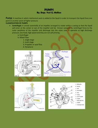
- 1. PUMPS By. Engr. Yuri G. Melliza Pump: A machine in which mechanical work is added to the liquid in order to transport the liquid from one point to another point of higher pressure. CLASSIFICATION OF PUMPS Centrifugal: It consist essentially of an impeller arranged to rotate within a casing so that the liquid will enter at the center or eye of the impeller and be thrown outward by centrifugal force to the outer periphery of the impeller and discharge into the outer case. It operates at high discharge pressure, low head, high speed and they are not self priming. a. Centrifugal b. Mixed Flow 1. single stage 2. multi stage 3. Propeller or axial flow 4. Peripheral
- 2. Rotary: It is a positive displacement pump consisting of a fixed casing containing gears, cams, screws, vanes, plungers or similar element actuated by the rotation of the drive shaft. A rotary pump traps a quantity of liquid and moves it along toward the discharge point. For a gear type rotary pump the unmeshed gears at the pump provides a space for the liquid to fill as the gears rotate. The liquid trapped between the teeth and the pump casing is eventually released at the discharge line. It operates at low heads, low discharge and is used for pumping viscous liquids like oil. a. cam c. gear b. screw d. vane
- 3. Reciprocating: It is a positive displacement unit wherein the pumping action is accomplished by the forward and backward movement of a piston or a plunger inside a cylinder usually provided with valves. a. Piston b. Direct Acting 1. single 2. duplex c. Crank and Flywheel d. Plunger e. Power Driven 1. simplex 2. duplex 3. triplex Deepwell pumps: It is used when pumping water from deep wells. The pump is lowered into the well and operated close to water level. They are usually motor driven with the motor being at the ground level and connected to the pump by a long vertical line shaft. a. Turbine b. Ejector or centrifugal c. reciprocating d. Airlift
- 4. For a final choice of a pump for a particular operation the following data is needed. Number of units required Nature of liquid Capacity Suction conditions Discharge conditions Intermittent or continuous service Total dynamic head Position of pump, vertical or horizontal Location, geographical, indoor, outdoor, elevation Type of power drive Pressure Gauge Pump Centerline (PCL)
- 5. FUNDAMENTAL EQUATIONS TOTAL DYNAMIC HEAD Ht 2 P 2 P1 γ v 2 v1 2 2g Z 2 Z1 HL FLUID POWER or WATER POWER WP = QHt KW DISCHARGE or CAPACITY Q = Asvs = Advd BRAKE or SHAFT POWER BP 2 TN PUMP EFFICIENCY P WP BP MP x 100% COMBIND PUMP-MOTOR EFFICIENCY C C x 100% BP MOTOR EFFICIENCY m KW 60,000 WP x 100% MP Pm MOTOR POWER For Single Phase Motor MP E I (cos ) 1000 KW For 3 Phase Motor MP 3 E I (cos ) 1000 KW meters
- 6. where: P – pressure in KPa v – velocity in m/sec z – elevation in meters z is positive if measured above datum z is negative if measured below datum Ht – total dynamic head in meters HL – head loss due to friction and turbulence in meters WP – water power of fluid power in KW Q – discharge or capacity in m3/sec - specific weight of liquid in KN/m3 A – cross sectional area in m2 BP – Brake or shaft power in KW T – BRAKE TORQUE IN Newton – meter (N – m) N – number of RPM MP – motor power in KW E – Energy in Volts I – current in Amperes Cos - Power Factor P – Pump efficiency m – motor efficiency c – combined pump – motor efficiency Centrifugal Pump Priming Most centrifugal pumps are not self-priming. In other words, the pump casing must be filled with liquid before the pump is started, or the pump will not be able to function. If the pump casing becomes filled with vapors or gases, the pump impeller becomes gas-bound and incapable of pumping. To ensure that a centrifugal pump remains primed and does not become gas-bound, most centrifugal pumps are located below the level of the source from which the pump is to take its suction. The same effect can be gained by supplying liquid to the pump suction under pressure supplied by another pump placed in the suction line.
- 7. FUNDAMENTAL EQUATIONS OF CENTRIFUGAL PUMPS 1. Total Head HT = nH n - number of stages H - head per stage 2. Specific Speed: Is the speed in RPM at which a theoretical pump geometrically similar to the actual pump would run at its best efficiency if proportion to deliver 1 m3/sec against a total head of 1 m. It serves as a convenient index of the actual pump type. NS N Q 0.0194 H 3 4 where: Q - flow for a single suction pump in m3/sec and H is the head per stage 3. Suction Specific Speed (S) S N Q 0.0194 NPSH 3 4 3 NS NPSH 4 S H NPSH - net positive suction head, meters 4. Net Positive Suction Head: The amount of pressure in excess of the vapor pressure of the liquid to prevent cavitation. NPSH = Hp Hz - Hvp - hfs , meters where: Hp - absolute pressure head at liquid surface at suction, m Hz - elevation of liquid surface at suction, above or below the pump centerline, m (+) if above PCL (-) if below PCL Hvp - vapor pressure head corresponding the temperature of the liquid, m hfs - friction head loss from liquid surface at suction to PCL.
- 8. 5. Cavitation: The formation of cavities of water vapor in the suction side of the pump due to low suction pressure. CAUSES OF CAVITATION o Sharp bends. o High temperature o High velocity o Rough surface o Low atmospheric pressure EFFECTS OF CAVITATION o Noise o Vibration o Corrosion o Decreased capacity 6. Cavitation Parameter: 4 NPSH H NS 3 S 7. Impeller Diameter; D 60 2gH N meter where: - peripheral velocity factor whose value ranges from 0.95 to1.09 8. Affinity Laws or Similarity Laws for Centrifugal Machines a. For Geometrically similar pumps Q ND3 Power N3D5 2D2 HN T N2D5 b. For pumps with Variable Speed and Constant impeller diameter QN Power N3 H N2 c. For pumps at Constant Speed with Variable impeller diameter QD Power D3 H D2
- 9. Positive Displacement Pump General A positive displacement pump is one in which a definite volume of liquid is delivered for each cycle of pump operation. This volume is constant regardless of the resistance to flow offered by the system the pump is in, provided the capacity of the power unit driving the pump or pump component strength limits are not exceeded. The positive displacement pump delivers liquid in separate volumes with no delivery in between, although a pump having several chambers may have an overlapping delivery among individual chambers, which minimizes this effect. The positive displacement pump differs from centrifugal pumps, which deliver a continuous flow for any given pump speed and discharge resistance. Positive displacement pumps can be grouped into three basic categories based on their design and operation. The three groups are reciprocating pumps, rotary pumps, and diaphragm pumps. Positive Displacement Pump Operation All positive displacement pumps operate on the same basic principle. This principle can be most easily demonstrated by considering a reciprocating positive displacement pump consisting of a single reciprocating piston in a cylinder with a single suction port and a single discharge port as shown in Figure 12. Check valves in the suction and discharge ports allow flow in only one direction. During the suction stroke, the piston moves to the left, causing the check valve in the suction line between the reservoir and the pump cylinder to open and admit water from the reservoir. During the discharge stroke, the piston moves to the right, seating the check valve in the suction line and opening the check valve in the discharge line. The volume of liquid moved by the pump in one cycle (one suction stroke and one discharge stroke) is equal to the change in the liquid volume of the cylinder as the piston moves from its farthest left position to its farthest right position.
- 10. Plunger Pumps Plunger Pumps Plunger Pumps are reciprocating positive displacement pumps which are generally configured in four ways: direct-acting or indirect-acting; simplex or duplex; single-acting or double-acting; and power pumps. Some reciprocating pumps are powered by prime movers that also have reciprocating motion, such pumps are powered by a reciprocating steam piston or plunger. The plunger rod of the steam piston may be directly connected to the liquid piston of the pump or it may be indirectly connected with a beam or linkage. Directacting piston pumps have a plunger on the liquid ( pump ) end that is directly driven by the pump rod ( also the piston rod or extension thereof ) and carries the piston of the power end. Indirect-acting pumps are driven by means of a beam or linkage connected to and actuated by the power piston rod of a separate reciprocating engine. A simplex plunger pump, sometimes referred to as a single piston plunger pump, is a pump having a single liquid ( pump ) cylinder. A duplex plunger pump is the equivalent of two simplex type pumps placed side by side on the same foundation. The driving of the pistons / plungers of a duplex pump is arranged in such a manner that when one piston is on its upstroke the other piston is on its down stroke, and vice versa. This arrangement doubles the capacity of the duplex pump compared to a simplex pump of comparable design. A single-acting plunger pump is one that takes a suction, filling the pump cylinder on the stroke in only one direction, called the suction stroke, and then forces the liquid out of the cylinder on the return stroke, called the discharge stroke. A double-acting plunger pump is one that, as it fills one end of the liquid cylinder, is discharging liquid from the other end of the cylinder. On the return stroke, the end of the cylinder just emptied is filled, and the end just filled is emptied. One possible arrangement for single-acting and doubleacting pumps is shown in Figure 13.
- 11. Power pumps convert rotary motion to low speed reciprocating motion by reduction gearing, a crankshaft, connecting rods and crossheads. Plungers are driven by the crosshead drives. Rod and piston construction, similar to duplex double-acting steam pumps, is used by the liquid ends of the low pressure, higher capacity units. The higher pressure units are normally single-acting plungers, and usually employ three (triplex) plungers. Three or more plungers substantially reduce flow pulsations relative to simplex and even duplex pumps. Power pumps typically have high efficiency and are capable of developing very high pressures. They can be driven by either electric motors or turbines. They are relatively expensive pumps and can rarely be justified on the basis of efficiency over centrifugal pumps. However, they are frequently justified over steam plunger pumps where continuous duty service is needed due to the high steam requirements of direct-acting plunger steam pumps. In general, the effective flow rate of plunger pumps decreases as the viscosity of the fluid being pumped increases because the speed of the pump must be reduced. In contrast to centrifugal pumps, the differential pressure generated by plunger reciprocating pumps is independent of fluid density. It is dependent entirely on the amount of force exerted on the piston. Rotary Pumps Rotary pumps operate on the principle that a rotating vane, screw, or gear traps the liquid in the suction side of the pump casing and forces it to the discharge side of the casing. These pumps are essentially self-priming due to their capability of removing air from suction lines and producing a high suction lift. In pumps designed for systems requiring high suction lift and self-priming features, it is essential that all clearances between rotating parts, and between rotating and stationary parts, be kept to a minimum in order to reduce slippage. Slippage is leakage of fluid from the discharge of the pump back to its suction. Due to the close clearances in rotary pumps, it is necessary to operate these pumps at relatively low speed in order to secure reliable operation and maintain pump capacity over an extended period of time. Otherwise, the erosive action due to the high velocities of the liquid passing through the narrow clearance spaces would soon cause excessive wear and increased clearances, resulting in slippage. There are many types of positive displacement rotary pumps, and they are normally grouped into three basic categories that include gear pumps, screw pumps, and moving vane pumps. Gear Pumps There are several variations of gear pumps. The simple gear pump shown in the illustration below, consists of two spur gears meshing together and revolving in opposite directions within a casing. Only a few thousandths of an inch clearance exists between the case and the gear faces and teeth extremities. Any liquid that fills the space bounded by two successive gear teeth and the case must follow along with the teeth as they revolve. When the gear teeth mesh with the teeth of the other gear, the space between the teeth is reduced, and the entrapped liquid is forced out the pump discharge pipe. As the gears revolve and the teeth disengage, the space again opens on the suction side of the pump, trapping new quantities of liquid and carrying it around the pump case to the discharge. As liquid is carried away from the suction side, a lower pressure is created, which draws liquid in through the suction line. With the large number of teeth usually employed on the gears, the discharge is relatively smooth and continuous, with small quantities of liquid being delivered to the discharge line in rapid succession. If designed
- 12. with fewer teeth, the space between the teeth is greater and the capacity increases for a given speed; however, the tendency toward a pulsating discharge increases. In all simple gear pumps, power is applied to the shaft of one of the gears, which transmits power to the driven gear through their meshing teeth. There are no valves in the gear pump to cause friction losses as in the reciprocating pump. The high impeller velocities, with resultant friction losses, are not required as in the centrifugal pump. Therefore, the gear pump is well suited for handling viscous fluids such as fuel and lubricating oils. Helix and Spur Type Gear Pumps There are two types of gears used in gear pumps in addition to the simple spur gear. One type is the helical gear. A helix is the curve produced when a straight line moves up or down the surface of a cylinder. The other type is the herringbone gear. A herringbone gear is composed of two helixes spiraling in different directions from the center of the gear. Spur, helical, and herringbone gears are shown in the Illustration below. The helical gear pump has advantages over the simple spur gear. In a spur gear, the entire length of the gear tooth engages at the same time. In a helical gear, the point of engagement moves along the length of the gear tooth as the gear rotates. This makes the helical gear operate with a steadier discharge pressure and fewer pulsations than a spur gear pump. The herringbone gear pump is also a modification of the simple gear pump. Its principal difference in operation from the simple spur gear pump is that the pointed center section of the space between two teeth begins discharging before the divergent outer ends of the preceding space complete discharging. This overlapping tends to provide a steadier discharge pressure. The power transmission from the driving to the driven gear is also smoother and quieter.
- 13. Lobe Type Gear Pump The lobe type pump shown below is another variation of the simple gear pump. It is considered as a simple gear pump having only two or three teeth per rotor; otherwise, its operation or the explanation of the function of its parts is no different. Some designs of lobe pumps are fitted with replaceable gibs, that is, thin plates carried in grooves at the extremity of each lobe where they make contact with the casing. The gib promotes tightness and absorbs radial wear.
- 14. Screw Type Positive Displacement PumpScrew Type Positive Displacement Pump There are many variations in the design of the screw type positive displacement, rotary pump. The primary differences consist of the number of intermeshing screws involved, the pitch of the screws, and the general direction of fluid flow. Two common designs are the two-screw, low-pitch, double-flow pump and the threescrew, high-pitch, double-flow pump. Two-Screw, Low-Pitch, Screw Pump The two-screw, low-pitch, screw pump consists of two screws that mesh with close clearances, mounted on two parallel shafts. One screw has a right-handed thread, and the other screw has a left-handed thread. One shaft is the driving shaft and drives the other shaft through a set of herringbone timing gears. The gears serve to maintain clearances between the screws as they turn and to promote quiet operation. The screws rotate in closely fitting duplex cylinders that have overlapping bores. All clearances are small, but there is no actual contact between the two screws or between the screws and the cylinder walls. The complete assembly and the usual flow path are shown in Figure 17. Liquid is trapped at the outer end of each pair of screws. As the first space between the screw threads rotates away from the opposite screw, a one-turn, spiral-shaped quantity of liquid is enclosed when the end of the screw again meshes with the opposite screw. As the screw continues to rotate, the entrapped spiral turns of liquid slide along the cylinder toward the center discharge space while the next slug is being entrapped. Each screw functions similarly, and each pair of screws discharges an equal quantity of liquid in opposed streams toward the center, thus eliminating hydraulic thrust. The removal of liquid from the suction end by the screws produces a reduction in pressure, which draws liquid through the suction line.
- 15. Three-Screw, High-Pitch, Screw Pump The three-screw, high-pitch, screw pump, shown in Figure 18, has many of the same elements as the twoscrew, low-pitch, screw pump, and their operations are similar. Three screws, oppositely threaded on each end, are employed. They rotate in a triple cylinder, the two outer bores of which overlap the center bore. The pitch of the screws is much higher than in the low pitch screw pump; therefore, the center screw, or power rotor, is used to drive the two outer idler rotors directly without external timing gears. Pedestal bearings at the base support the weight of the rotors and maintain their axial position. The liquid being pumped enters the suction opening, flows through passages around the rotor housing, and through the screws from each end, in opposed streams, toward the center discharge. This eliminates unbalanced hydraulic thrust. The screw pump is used for pumping viscous fluids, usually lubricating, hydraulic, or fuel oil.
- 16. Rotary Vane Positive Displacement Pump The rotary moving vane pump shown below is another type of positive displacement pump used. The pump consists of a cylindrically bored housing with a suction inlet on one side and a discharge outlet on the other. A cylindrically shaped rotor with a diameter smaller than the cylinder is driven about an axis placed above the centerline of the cylinder. The clearance between rotor and cylinder is small at the top but increases at the bottom. The rotor carries vanes that move in and out as it rotates to maintain sealed spaces between the rotor and the cylinder wall. The vanes trap liquid or gas on the suction side and carry it to the discharge side, where contraction of the space expels it through the discharge line. The vanes may swing on pivots, or they may slide in slots in the rotor.
- 17. Diaphragm Pumps Diaphragm pumps are also classified as positive displacement pumps because the diaphragm acts as a limited displacement piston. The pump will function when a diaphragm is forced into reciprocating motion by mechanical linkage, compressed air, or fluid from a pulsating, external source. The pump construction eliminates any contact between the liquid being pumped and the source of energy. This eliminates the possibility of leakage, which is important when handling toxic or very expensive liquids. Disadvantages include limited head and capacity range, and the necessity of check valves in the suction and discharge nozzles. An example of a diaphragm pump is shown below.
- 18. Double Diaphragm Pumps Review Double Diaphragm Pumps are classified as positive displacement pumps because the diaphragms acts as a limited displacement piston. The pump is design and constructed such that two opposed diaphragms are driven by the reciprocating motion by mechanical linkage, compressed air, or fluid from a pulsating, external source. Double diaphragm pumps are design to delivery twice the flow of single diaphragm type pumps. The pump and diaphragms construction eliminates any contact between the liquid being pumped and the source of energy. This eliminates the possibility of leakage, which is important when handling toxic or very expensive liquids. Disadvantages include limited head and capacity range, and the necessity of check valves in the suction and discharge nozzles. An example of a diaphragm pump is shown below. Positive Displacement Pump Characteristic Curve Positive displacement pumps deliver a definite volume of liquid for each cycle of pump operation. Therefore, the only factor that effects flow rate in an ideal positive displacement pump is the speed at which it operates. The flow resistance of the system in which the pump is operating will not effect the flow rate through the pump. Figure 21 shows the characteristic curve for a positive displacement pump. The dashed line within the illustration below, shows actual positive displacement pump performance. This line reflects the fact that as the discharge pressure of the pump increases, some amount of liquid will leak from the discharge of the pump back to the pump suction, reducing the effective flow rate of the pump. The rate at which liquid leaks from the pump discharge to its suction is called slippage.
- 19. Positive Displacement Pump Protection Positive displacement pumps are normally fitted with relief valves on the upstream side of their discharge valves to protect the pump and its discharge piping from over pressurization. Positive displacement pumps will discharge at the pressure required by the system they are supplying. The relief valve prevents system and pump damage if the pump discharge valve is shut during pump operation or if any other occurrence such as a clogged strainer blocks system flow. Hydrostatic Pumps About Hydrostatic Pumps, are used to convert fluid power into mechanical power. Hydrostatic pumps are used as a source of fluid flow. When the pressure within the associated system builds to the level required to over come system mechanical load(s) then the pressure will drop as the fluid begins to travel through devices performing mechanical work. Many Hydrostatic pumps and motors are reversible. Not all pumps are capable of operating in opposing directions of rotation due to design limitation of seals and rotational mechanism. Hydrostatic pumps are available and designed to operate at most desired speeds. Metering Pumps Review Metering Pumps are positive displacement type pumps which deliver a specific amount fluid into a system. Metering pumps are available in a wide variety of flow, pressure, and fluid compatibility. Metering pumps may be driven by an variable or fixed velocity electric motor or a reciprocating engine power take-off (PTO). Pump metering rate may be fixed or adjustable. Metering pumps are available with both mechanical and electronic flow / metering control mechanisms. Metering pumps are used when one or more of the following are required within a fluid system: Contamination or leakage between fluid systems must be controlled. Flow must be specifically controlled relative to discharge pressure. Fluid output capacity must be accurate. Fluids system isolation must be present.
- 20. Metering pump performance selection considerations: Downturn ration accuracy, also called range, which is the pumps capacity to maintain the required repeatability on various operating conditions. Flow performance linearity, which is the metering pumps ability to achieve performance relative to a predicted or measured performance curve. This performance curve is normally pressure vs metering rate. The lower the percentage of the pumps deviation the more accurate the pump is. Steady state accuracy is the metering pumps ability to maintain a constant flow while continuously running. Normally this is specified in percentage. Pump isolation requirements of the pump should be matched to the fluid system isolation requirements. FUNDAMENTAL EQUATIONS FOR RECIPROCATING PUMPS Specification: Ds x Dw x L where: Ds - diameter of steam cylinder Dw - diameter of water cylinder L - length of stroke Q ηV x 100% VD 1. Volumetric Efficiency where: Q - capacity, m3/sec VD - displacement volume, m3/sec F w e m Fs F w Ds Dw (Dw) 2 (P d P su ) 4 (P d P su ) e m (P s P e ) KPa
- 21. 2. Displacement Volume a. For Single acting VD 2 L(D W ) Nn' m 3 4(60) sec b. For Double acting without considering piston rod VD L(D 2 W ) Nn' m 3 4(60) sec c. For Double acting considering piston rod VD LNn' 4(60) 2D W 2 - d 2 m 3 sec where: N - no. of strokes per minute L - length of stroke, m D - diameter of bore, . d - diameter of piston rod, m n' - no. of cylinders n' = 1 (For Simplex) n' = 2 (For Duplex) n' = 3 (For Triplex) 3. Percent Slip %Slip = 100 - v 4. Slip Slip = VD - Q 5. Thermal Efficiency e 3600(WP) m s (h s h e ) x 100%
- 22. where: hs - enthalpy of supply steam, KJ/kg he - enthalpy of exhaust steam, KJ/kg ms - steam flow rate, kg/hr FP - fluid power, KW 6. Force produced and acting on the piston rod 2 Fs D S (P s P e ) 4 KPa where: Ps - supply steam pressure, KPa Pe - exhaust steam pressure, KPa Ds - diameter of steam cylinder, m (Ps - Pe) - mean effective pressure 7. Force transmitted to the liquid piston F w e m Fs F w Ds Dw (Dw) 2 (P d P su ) 4 KPa (P d P su ) e m (P s P e ) where: em - mechanical efficiency Psu - suction pressure of water cylinder, KPa Pd - discharge pressure of water cylinder, KPa
- 23. 8. Pump Duty: Work done on the water cylinder expressed in Newton-meter per Million Joules Pump Duty 9.81m w (H d H su ) x 10 1000m s 6 (h s - h e ) N -m Million Joules where: mw - water flow rate, kg/hr Hd - discharge head of pump, m Hsu - suction head of pump, m 9. Pump Speed V = 43.64(L)1/2(ft), m/min 2 VD (D W ) Vn' m 4(60) sec 3 where: ft - temperature correction factor L - length of stroke, m 10. Temperature Correction Factor ft = 1 For cold water = 0.85 for 32.2C water = 0.71 for 65.5C water = 0.55 for 204.4C water
- 24. 11. For Indirect Acting pumps N 907 f t L