1. INTERNAL COMBUSTION ENGINE
Module – II
Main components of reciprocating IC engines:
Cylinder: It is the main part of the engine inside which piston reciprocates to and fro. It
should have high strength to withstand high pressure above 50 bar and temperature above
2000
o
C. The ordinary engine is made of cast iron and heavy duty engines are made of steel
alloys or aluminum alloys. In the multi-cylinder engine, the cylinders are cast in one block
known as cylinder block.
Cylinder head: The top end of the cylinder is covered by cylinder head over which inlet and
exhaust valve, spark plug or injectors are mounted. A copper or asbestos gasket is provided
between the engine cylinder and cylinder head to make an air tight joint.
Piston: Transmit the force exerted by the burning of charge to the connecting rod. Usually
made of aluminium alloy which has good heat conducting property and greater strength at
higher temperature.
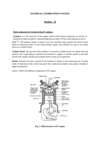
Figure 1 shows the different components of IC engine.
Fig. 1. Different parts of IC engine
2. Piston rings: These are housed in the circumferential grooves provided on the outer surface
of the piston and made of steel alloys which retain elastic properties even at high
temperature. 2 types of rings- compression and oil rings. Compression ring is upper ring of
the piston which provides air tight seal to prevent leakage of the burnt gases into the lower
portion. Oil ring is lower ring which provides effective seal to prevent leakage of the oil into
the engine cylinder.
Connecting rod: It converts reciprocating motion of the piston into circular motion of the
crank shaft, in the working stroke. The smaller end of the connecting rod is connected with
the piston by gudgeon pin and bigger end of the connecting rod is connected with the crank
with crank pin. The special steel alloys or aluminium alloys are used for the manufacture of
connecting rod.
Crankshaft: It converts the reciprocating motion of the piston into the rotary motion with the
help of connecting rod. The special steel alloys are used for the manufacturing of the
crankshaft. It consists of eccentric portion called crank.
Crank case: It houses cylinder and crankshaft of the IC engine and also serves as sump for
the lubricating oil.
Flywheel: It is big wheel mounted on the crankshaft, whose function is to maintain its speed
constant. It is done by storing excess energy during the power stroke, which is returned
during other stroke.
Terminology used in IC engine:
1. Cylinder bore (D): The nominal inner diameter of the working cylinder.
2. Piston area (A): The area of circle of diameter equal to the cylinder bore.
3. Stroke (L): The nominal distance through which a working piston moves between two
successive reversals of its direction of motion.
4. Dead centre: The position of the working piston and the moving parts which are
mechanically connected to it at the moment when the direction of the piston motion is
reversed (at either end point of the stroke).
(a) Bottom dead centre (BDC): Dead centre when the piston is nearest to the crankshaft.
(b) Top dead centre (TDC): Dead centre when the position is farthest from the crankshaft.
5. Displacement volume or swept volume (Vs): The nominal volume generated by the
working piston when travelling from the one dead centre to next one and given as,
Vs=A × L
6. Clearance volume (Vc): the nominal volume of the space on the combustion side of the
piston at the top dead centre.
3. 7. Cylinder volume (V): Total volume of the cylinder.
V= Vs + Vc
8. Compression ratio (r):
Four stroke engine:
- Cycle of operation completed in four strokes of the piston or two revolution of the
piston.
(i) Suction stroke (suction valve open, exhaust valve closed)-charge consisting of
fresh air mixed with the fuel is drawn into the cylinder due to the vacuum pressure
created by the movement of the piston from TDC to BDC.
(ii) Compression stroke (both valves closed)-fresh charge is compressed into
clearance volume by the return stroke of the piston and ignited by the spark for
combustion. Hence pressure and temperature is increased due to the combustion
of fuel
(iii) Expansion stroke (both valves closed)-high pressure of the burnt gases force the
piston towards BDC and hence power is obtained at the crankshaft.
(iv) Exhaust stroke (exhaust valve open, suction valve closed)- burned gases expel out
due to the movement of piston from BDC to TDC.
Figure 2 show the cycle of operation of four stroke engine.
Fig. 2. Cycle of operation in four stroke engine
Two stroke engine:
-No piston stroke for suction and exhaust operations
-Suction is accomplished by air compressed in crankcase or by a blower
4. -Induction of compressed air removes the products of combustion through exhaust ports
-Transfer port is there to supply the fresh charge into combustion chamber
Figure 3 represents operation of two stroke engine
Fig. 3. Cycle of operation in two stroke engine