SlideShare une entreprise Scribd logo
1  sur  34
Télécharger pour lire hors ligne
Overview
The EFl/TCCS system is an electronic
control system which provides Toyota
engines with the means to properly meter
the fuel and control spark advance angle.
The system can be divided into three distinct
elements with three operational phases.
The three system elements are:
• Input Sensors
• Electronic Control Unit (A Microcomputer)
• Output Actuators
ENGINE CONTROLS - INPUT SENSORS
Page 1 © Toyota Motor Sales, U.S.A., Inc. All Rights Reserved.
The electronic control system is responsible
for monitoring and managing engine
functions which were previously performed
by mechanical devices like carburetors,
vacuum, and centrifugal advance units. In an
electronic control system, these functions
are managed in three phases.
• The input phase of electronic control allow
the Electronic Control Unit (ECU) to monitor
engine operating conditions, utilizing
information from the input sensors.
• The process phase of electronic control
requires the ECU to use this input
information to make operating decisions
about the fuel and spark advance systems.
• The output phase of electronic control
requires the ECU to control the output
actuators, the fuel injectors, and igniter to
achieve the desired fuel metering and
spark timing.
In this chapter, we will explore the details of
the electronic control system hardware and
software. The chapter starts with a thorough
examination of the system's input sensor
circuits and the ECU power distribution
system. It concludes with a closer look at the
ECU process functions and the control
strategy use( for optimum fuel metering and
spark advance angle control.
The Microcomputer
The heart of the TCCS system is a
microcomputer. A microcomputer is a
device which receives information,
processes it, and makes decisions based
on a set of program instructions. The
microcomputer exercises control over the
output actuators to carry out these
instructions.
The use of microcomputers has taken the
science of engine management into the
space age by increasing the speed with
which information can be processed and
allowing the electronic control system to
manage more engine functions. With the
ability to process information so rapidly, the
modern ECU is capable of carrying out its
programmed instructions with extreme
accuracy. Engine management can address
virtually every condition the engine will
encounter so that for any engine condition,
the ECU will deliver optimum fuel and spark.
Evolution of Toyota's Electronic Fuel
Injection Systems
Early Conventional EFI computers were first
configured from analog circuits, and they
controlled only fuel delivery and injection. The
modem Electronic Control Units (ECU) utilize
digital circuits and microprocessors which
have served to improve EFI system
capabilities.
Modern TCCS engine controls, introduced to
the U.S.A. market in 1983, are capable of
managing fuel delivery, idle speed control
(ISC), electronic spark advance (ESA), and
emissions systems with extraordinary speed
and accuracy.
In the evolution of Toyota's fuel injection,
three levels of electronic control refinements
have taken place.
• Conventional EFI
• P7/EFI
• EFI/TCCS
The main difference between these systems
is the capability of the ECU. These
capabilities have grown from simple fuel
control to the addition of self-diagnostics to
the control of ignition spark advance and
more. The following chart summarizes basic
capabilities by system and can be used as a
guide in identification and troubleshooting.
ENGINE CONTROLS - INPUT SENSORS
Page 2 © Toyota Motor Sales, U.S.A., Inc. All Rights Reserved.
System identification is relatively simple.
• The Conventional EFI system has no check
engine light.
• The P7/EFI system has a check engine
light but has a mechanical advance
distributor.
• The EFI/TCCS system has a check engine
light and an electronic advance distributor.
The Input Sensors,
Information Source for the ECU
In an electronic control system, the ECU
uses its sensors in much the same manner
as we use our five senses. Our sense of
touch tells us when things are hot or cold; our
sense of hearing allows us to distinguish
one sound from another; our sense of smell
tells us when fresh coffee is brewing
somewhere nearby. Sensors give the ECU
similar abilities: the ability to feel the
temperature of the engine coolant, to listen
for the sound of detonation, and to smell the
exhaust stream for the presence of sufficient
oxygen.
This lesson on input sensors will address
how each major ECU input sensor circuit
works. Each sensor circuit will be broken
down so you can see its individual
components: the sensor, electrical wiring,
and the ECU.
ENGINE CONTROLS - INPUT SENSORS
Page 3 © Toyota Motor Sales, U.S.A., Inc. All Rights Reserved.
Overview
The EFl/TCCS system is an electronic
control system which provides Toyota
engines with the means to properly meter
the fuel and control spark advance angle.
The system can be divided into three distinct
elements with three operational phases.
The three system elements are:
• Input Sensors
• Electronic Control Unit (A Microcomputer)
• Output Actuators
ENGINE CONTROLS - INPUT SENSORS
Page 4 © Toyota Motor Sales, U.S.A., Inc. All Rights Reserved.
Input Sensors Used in Basic
Injection and Spark Calculation
Engine Air Flow Sensing
Vane Type Air Flow Meters
(Vs, General Information)
The vane type air flow meter is located in the
air induction system inlet pipe between the
air cleaner and the throttle body. It is
composed of the measuring plate,
compensation plate, return spring,
potentiometer, and by-pass passage. The
sensor also incorporates the idle mixture
adjusting screw (factory sealed), the fuel
pump switch, and the intake air temperature
sensor (which will be addressed later in this
lesson). Because intake air volume is a
direct measure of the load placed on an
engine, the vane type air flow meter provides
the most important input to the ECU for fuel
and spark calculations.
When air passes through the air flow meter,
it forces the measuring plate open to a point
where it balances with the force of the return
spring. The damping chamber and
compensation plate prevent vibration of the
measuring plate during periods of sudden
intake air volume changes.
The potentiometer, which is connected to the
measuring plate and rotates on the same
axis, converts the mechanical movement of
the measuring plate into a variable voltage
signal. Movement of the measuring plate and
the analog voltage signal produced by this
sensor are proportional to the volume of air
entering the intake manifold.
Vane Air How Meter Electrical Circuit
The sensor movable contact is attached to
the measuring plate and rides on a fixed
resistor wired between the reference voltage
input and the ground. As the volume of air
entering the engine increases, the movable
contact moves across the fixed resistor,
causing a change in signal output voltage.
There are two designs of vane air flow
meters used on Toyota L type EFI systems.
The first design generates a signal which
varies from low voltage at low air volumes to
high voltage at high air volumes. The second
design sensor has opposite signal
characteristics. These sensors also operate
on different reference voltages. Both sensor
designs integrate an intake air temperature
sensor into the air flow meter.
ENGINE CONTROLS - INPUT SENSORS
Page 5 © Toyota Motor Sales, U.S.A., Inc. All Rights Reserved.
First Design Vane Air How Meter
The first design air flow meter is found on all
Conventional EFI engines and many later
model TCCS equipped engines. This sensor
has an electrical connector with seven
terminals, four of which are used for air flow
measurement.
Air Flow Sensor Terminal Identification
(First Design Sensor)
The air flow meter and ECU are wired as
shown in the diagram. Signal characteristics
are depicted by the accompanying graph. The
use of battery voltage, VB, as a sensor input
necessitates the use of the Vc terminal as a
constant reference signal for the ECU. This is
because battery voltage may change with
variances in electrical load and ambient
temperatures. Without the use of a constant
reference voltage, these changes would
cause a change in the Vs signal value
recognized by the ECU.
ENGINE CONTROLS - INPUT SENSORS
Page 6 © Toyota Motor Sales, U.S.A., Inc. All Rights Reserved.
Second Design Air How Meter
The second design air flow meter was
introduced on the '85 5M-GE engine, and its
use expanded with many late model TCCS
equipped engines. This sensor has an
electrical connector with seven terminals,
three of which are used for air flow
measurement.
Air Flow Sensor Terminal Identification
(Second Design Sensor)
The air flow meter and ECU are wired as
shown in the diagram; signal characteristics
are depicted by the accompanying graph. The
use of a regulated 5 volt reference eliminates
the need for the VB terminal with this sensor
circuit.
Resistors R1 and R2 provide self diagnostic
capabilities and allow for a fail-safe voltage at
the ECU in the event of an open circuit. These
two resistors have a very high resistance
value (relative to r1 and r2) and essentially
have no electrical effect on the circuit under
normal operating conditions. They will,
however, affect the open circuit voltage
measured on the Vs wire at the ECU.
ENGINE CONTROLS - INPUT SENSORS
Page 7 © Toyota Motor Sales, U.S.A., Inc. All Rights Reserved.
Karman Vortex Air Flow Meter (Ks)
The Karman vortex air flow meter is currently
used on the 7M-GTE Toyota engine and the
2JZ-GE and 1UZ-FE Lexus engines. It is
located in the air induction system inlet pipe
between the air cleaner and the throttle body.
The sensor is composed of a photocoupler
and mirror, a vortex generator, and an
integrated circuit (IC) which together,
measure the frequency of the vortices
generated by air entering the intake system.
When compared with the vane type air flow
meter, the Karman vortex meter is smaller,
lighter, and offers less restriction to incoming
air. Similar to the vane type air meter, the
Karman vortex meter integrates the intake air
temperature sensor into the meter assembly.
The sensor has an electrical connector with
five terminals, three of which are used for air
flow measurement.
Karman Vortex Air Flow Meter
Terminal Identification
ENGINE CONTROLS - INPUT SENSORS
Page 8 © Toyota Motor Sales, U.S.A., Inc. All Rights Reserved.
The Karman vortex air flow meter and ECU
are wired as shown in the diagram. Signal
characteristics are represented by the
illustration of the variable frequency square
wave. Because of the pull-up resistor wired
between the Vcc and Ks circuit, the Ks signal
will go to 5 volts if the circuit is opened.
When air passes through the air flow meter,
the vortex generator creates a swirling of the
air downstream. This swirling effect is
referred to as a "Karman vortex." The
frequency of this Karman vortex varies with
the velocity of the air entering the air flow
meter and other variables. The photocoupler
and metal foil mirror are used to detect
changes in these vortices.
ENGINE CONTROLS - INPUT SENSORS
Page 9 © Toyota Motor Sales, U.S.A., Inc. All Rights Reserved.
The metal foil mirror is used to reflect light
from the LED to the photo transistor. The foil
is positioned directly above a pressure
directing hole which causes it to oscillate
with the changes in vortex frequency. As the
mirror
oscillates, the 5 volt Vcc reference is
switched to ground by a photo transistor
within the sensor. The resulting digital signal
is a 5 volt square wave which increases in
frequency in proportion to increases in intake
air flow.
ENGINE CONTROLS - INPUT SENSORS
Page 10 © Toyota Motor Sales, U.S.A., Inc. All Rights Reserved.
Manifold Absolute Pressure Sensor
The manifold absolute pressure sensor
(sometimes referred to as vacuum sensor)
is used on engines equipped with D type
EFI. It is typically located somewhere on the
bulkhead with a vacuum line leading directly
to the intake manifold. It measures intake air
volume by monitoring changes in manifold
absolute pressure, a function of engine load.
The sensor consists of a piezoresistive
silicon chip and an Integrated Circuit (IC). A
perfect vacuum is applied to one side of the
silicon chip and manifold pressure applied to
the other side. When pressure in the intake
manifold changes, the silicon chip flexes,
causing a change in its resistance. The
varying resistance of the sensor causes a
change in signal voltage at the PIM (Pressure
Intake Manifold) terminal.
ENGINE CONTROLS - INPUT SENSORS
Page 11 © Toyota Motor Sales, U.S.A., Inc. All Rights Reserved.
The manifold absolute pressure sensor has
an electrical connector with three terminals.
Manifold Absolute Pressure Sensor
Terminal Identification
The sensor and ECU are wired as shown in
the diagram. As manifold pressure increases
(approaches atmospheric pressure) there is
a proportionate increase in PIM signal
voltage. This analog signal characteristic is
depicted in the accompanying graph.
TO check sensor calibration, signal voltage
should be checked against the standards
shown on the graph, and a voltage drop
check should be performed over the entire
operating range of the sensor.
ENGINE CONTROLS - INPUT SENSORS
Page 12 © Toyota Motor Sales, U.S.A., Inc. All Rights Reserved.
Engine Speed and
Crankshaft Angle Sensing
On TCCS equipped engines, the Ne and G1
signals inform the ECU of engine rpm and
crankshaft angle. This information, along
with information from the air flow or manifold
pressure sensor, allows the ECU to
calculate the engine's basic operating load.
Based on measured load, basic injection
and spark advance angle can be accurately
calculated.
Ne Signal (Number of Engine Revolutions)
The Ne signal generator consists of a pickup
coil and toothed timing rotor. The number of
teeth on the signal timing rotor is determined
by the system used. The Ne sensor
produces an alternating current waveform
signal and is of critical importance to the
ECU. If this signal fails to reach the ECU, the
engine will not run.
G or G1 Signal (Group #1)
The G signal generator is very similar to the
Ne signal generator. The G1 signal
represents the standard crankshaft angle
and is used by the ECU to determine ignition
and injection timing in relation to TDC.
Depending on engine, there are different
variations of Ne and G1 signal generators.
The following illustrations show the
relationship between the Ne and G1 signals
and the different variations of signal
generators.
ENGINE CONTROLS - INPUT SENSORS
Page 13 © Toyota Motor Sales, U.S.A., Inc. All Rights Reserved.
ENGINE CONTROLS - INPUT SENSORS
Page 14 © Toyota Motor Sales, U.S.A., Inc. All Rights Reserved.
lGf Signal
The IGf signal is generated by the igniter on
EFI/TCCS systems. The ECU supplies a 5
volt reference through a pull-up resistor to
the lGf signal generation circuit in the igniter.
When a spark plug fires, the IGf signal
generation circuit pulls the five volts to
ground, causing a pulse to be sensed at the
ECU. One pulse is generated by the igniter
for each ignition event which is carried out.
IG Signal
On Conventional EFI engines, the IG signal
is used to inform the ECU of engine rpm.
This signal is generated directly from the coil
negative terminal or from an electrically
equivalent point inside the igniter on the early
The IGf signal confirms that ignition has
actually occurred. In the event of a failure to
trigger an ignition event, the ECU will shut
down injector pulses to protect the catalyst
from flooding with raw fuel. Typically this fail-
safe shutdown occurs within eight to eleven
IGt signals after the IGf signal is lost. This
condition can occur with any primary ignition
system fault, an igniter failure, a problem with
the IGf circuit wiring, or with a faulty ECU.
P-7 2S-E engine. Conventional EFI engines
do not use an Ne or G sensor and do not use
an IGf signal. The IG signal is also used by
the ECU to trigger injection pulses; therefore,
if this signal is lost, the engine will stall for
lack of injection pulse.
ENGINE CONTROLS - INPUT SENSORS
Page 15 © Toyota Motor Sales, U.S.A., Inc. All Rights Reserved.
Input Sensors Used For Injection
and Spark Corrections
Water Temperature Sensor (THW)
The water temperature sensor is typically
located near the cylinder head water outlet. It
monitors engine coolant temperature by
means of an internally mounted thermistor.
The thermistor has a negative temperature
coefficient (NTC), so its resistance value
decreases as coolant temperature rises.
The accompanying resistance graph
demonstrates this relationship.
The water temperature sensor is required
because fuel vaporization is less efficient
when the engine is cold. Internal engine
friction is also higher during cold operation,
increasing operating load. The THW signal is
used by the ECU to determine how much fuel
enrichment correction is necessary to provide
good cold engine performance. In addition to
fuel calculations, the THW signal plays a
major role is almost every other function that
the ECU serves.
ENGINE CONTROLS - INPUT SENSORS
Page 16 © Toyota Motor Sales, U.S.A., Inc. All Rights Reserved.
The water temperature sensor has a two
terminal electrical connector attached to
either end of the thermistor element.
Water Temperature Sensor
Terminal Identification
The sensor and ECU are wired as shown in
the diagram. Signal voltage characteristics
are determined by the value of the pull-up
resistor, located inside the ECU, either 2.7
KΩ or 5 M. The graphs accompanying the
diagram give approximate voltage
specifications. To determine which pull-up
resistor a particular ECU uses, refer to the
technical reference charts in Appendix B of
this book.
ENGINE CONTROLS - INPUT SENSORS
Page 17 © Toyota Motor Sales, U.S.A., Inc. All Rights Reserved.
Air Temperature Sensor (THA)
The air temperature sensor monitors the
temperature of air entering the intake
manifold by means of a thermistor. This
thermistor is integrated within the air flow
meter on L type systems and located in the
intake air hose just downstream of the air
cleaner on D type systems. It has the same
resistance characteristics as the water
temperature sensor.
ENGINE CONTROLS - INPUT SENSORS
Page 18 © Toyota Motor Sales, U.S.A., Inc. All Rights Reserved.
This sensor has a two-terminal electrical
connector attached to either end of the
thermistor element.
Air Temperature Sensor
Terminal Identification
The air temperature sensor and ECU are
wired as shown in the diagram. Resistance
and voltage signal characteristics are
represented by the accompanying graphs.
An intake air temperature monitor is
necessary in the EFI system because the
pressure and density of air changes with
temperature. Because air is more dense
when cold, the ECU factors intake air
temperature into the fuel correction program.
ENGINE CONTROLS - INPUT SENSORS
Page 19 © Toyota Motor Sales, U.S.A., Inc. All Rights Reserved.
Throttle Angle and
Closed Throttle Sensing
Throttle position sensors typically mount on
the throttle body, directly to the end of the
throttle shaft. Depending on engine and
model year, Toyota EFI equipped engines
use one of two different types of throttle
position sensors. These sensors are
categorized as on-off type and linear type.
The linear type sensor is typically used on
most late model Electronically Controlled
Transmission (ECT) equipped vehicles.
The on-off type sensor circuits can be further
broken down into first and second design.
This sensor is typically used on manual or
non-ECT transmission equipped
applications.
All throttle sensors, regardless of design,
supply the ECU with vital information about
idle status and driver demand. This
information is used by the ECU to make
judgments about power enrichment,
deceleration fuel cut-off, idle stability, and
spark advance angle corrections.
ENGINE CONTROLS - INPUT SENSORS
Page 20 © Toyota Motor Sales, U.S.A., Inc. All Rights Reserved.
On-Off Type Throttle Position
Sensors (IDL & PSW)
The on-off type throttle position sensor is a
simple switch device which, depending on
application, either pulls a reference voltage
to ground or sends a battery voltage signal to
the ECU. The on-off throttle position sensors
are electrically wired to the ECU as shown in
the accompanying diagrams.
First Design On-Off Type Sensor
The first design sensor is used on
Conventional EFI engines. It utilizes a dual
position contact which switches a battery
voltage signal to either the IDL or PSW inputs
at the ECU. This switching action causes the
voltage signal at the ECU to go high
whenever the switch contacts are closed.
Referring to the voltage graph, IDL signal
voltage is high when the throttle is closed
and goes low when the throttle exceeds a 1.5'
opening. PSW voltage is low until the throttle
exceeds about a 70' opening; then it goes
high.
ENGINE CONTROLS - INPUT SENSORS
Page 21 © Toyota Motor Sales, U.S.A., Inc. All Rights Reserved.
Second Design On-Off Type Sensor
The second design sensor, which is used
on many late model TCCS equipped
engines, utilizes a dual position contact to
switch an ECU reference voltage to ground.
This switching action causes the signal at
the ECU to go low whenever the switch
contacts are closed.
Referring to the voltage graph, IDL signal
voltage is low when the throttle is closed and
goes high when the throttle exceeds a 1.5'
opening. PSW voltage is high until the throttle
opens to about 70’; then it goes low.
The three wire electrical connector terminals
are identified as follows.
1 st and 2nd Design On-Off Throttle
Position Sensor Terminal Identification
ENGINE CONTROLS - INPUT SENSORS
Page 22 © Toyota Motor Sales, U.S.A., Inc. All Rights Reserved.
On '83 and '84 Cressidas/Supras and '83
through '86 Camrys equipped with an
Electronically Controlled Transmission
(ECT), a modified sensor, which
incorporates three additional signal wires
designated L1, L2, and L3, is used. These
signals represent throttle opening angles in
between the 1.5' IDL and 70' PSW signals.
The L1, L2, and L3 signals are used by the
ECT system and are generated in a similar
manner as the IDL and PSW signals on the
2nd design sensor. The TCCS ECU only
uses the IDL and PSW signals from this
sensor.
Linear Throttle Position Sensor (VTA)
The linear throttle position sensor is
mounted to the throttle body. It is composed
of two movable contacts, a fixed resistor, and
four electrical terminals. The two movable
contacts move along the same axis as the
throttle valve. One is used for the throttle
opening angle signal (VTA) and the other for
the closed throttle signal (IDL).
ENGINE CONTROLS - INPUT SENSORS
Page 23 © Toyota Motor Sales, U.S.A., Inc. All Rights Reserved.
As the throttle opens, a potentiometer circuit
converts the mechanical movement of the
throttle valve into a variable voltage signal.
The voltage produced by this sensor is
proportional to the throttle valve opening
angle.
The Linear Throttle Position Sensor has an
electrical connector with four terminals.
Linear Throttle Position Sensor
Terminal Identification
The sensor and ECU are wired as shown in
the diagram. As the throttle valve opens, the
sensor VTA contact moves closer to the
voltage source, causing a signal voltage
increase.
At closed throttle, the IDL contact is held
closed. This pulls the IDL signal circuit to
ground. As the throttle opens, the IDL contact
breaks, causing the digital IDL signal voltage
to go from low to high. These signal
characteristics are depicted in the
accompanying graph.
Resistors R1 and R2 provide self diagnostic
capabilities and allow for a fail-safe voltage at
the ECU in the event of an open circuit. These
two resistors have a very high resistance
value and essentially have no electrical effect
on the circuit under normal operating
conditions. They will, however, affect the open
circuit voltage measured on the VTA wire at
the ECU.
ENGINE CONTROLS - INPUT SENSORS
Page 24 © Toyota Motor Sales, U.S.A., Inc. All Rights Reserved.
Exhaust Oxygen Content Sensing (OX1)
Exhaust oxygen sensors are used on Toyota
EFI and EFI/TCCS equipped engines to
provide air/fuel ratio feedback information to
the ECU. This information is used to
constantly adjust the air/fuel ratio to
stoichiometry during warm idle and cruise
operating conditions. The stoichiometric
air/fuel ratio delivers one pound of fuel for
each 14.7 pounds of air entering the intake
manifold and results in the most efficient
combustion and catalyst operation. When the
electronic control system is using
information from the oxygen sensor to adjust
air/fuel ratio, the system is said to be
operating in closed loop.
Exhaust oxygen sensor efficiency is
dependent upon its operating temperature.
The sensor will only generate an accurate
signal when it has reached its minimum
operating temperature of 750'F. Therefore,
the oxygen sensor is typically located in the
exhaust stream at the manifold collector.
This location is close enough to the exhaust
valves to maintain adequate operating
temperature under most driving conditions
and allows a representative exhaust sample
from all cylinders.
Open and Closed Loop Operation
In addition to promoting efficient combustion
and catalyst operation, a stoichiometric
air/fuel ratio also promotes excellent fuel
economy. This relatively lean mixture is
desirable during cruise and idle operation;
however, other operating conditions often
require a richer air/fuel ratio. When the
electronic control system ignores signals
from the oxygen sensor and does not correct
the air/fuel ratio to 14.7:1, the system is said
to be operating in open loop.
In order to prevent overheating of the catalyst
and ensure good driveability, open loop
operation is required under the following
conditions:
• During engine starting
• During cold engine operation
• During moderate to heavy load operation
• During acceleration and deceleration
During open loop operation, the ECU ignores
information from the exhaust oxygen sensor
and bases fuel injection duration calculations
exclusively on the other input sensors.
ENGINE CONTROLS - INPUT SENSORS
Page 25 © Toyota Motor Sales, U.S.A., Inc. All Rights Reserved.
Exhaust Oxygen Sensors
Toyota engines utilize two different types of
oxygen sensors. The zirconium dioxide sensor is
used on all engines except the '90 and later 4A-GE
Federal and 3VZ-E California 2WD truck engines.
These two engines use a titania oxide sensor.
To bring the system to closed loop operation more
rapidly, many engines use a heated exhaust
oxygen sensor. The heated sensor provides more
accurate exhaust sampling during idle and low
speed operation when exhaust temperatures are
relatively low. Use of a heated sensor allows
closed loop operation earlier during engine warm-
up cycles and also allows more flexibility in
oxygen sensor location. These factors help in
meeting strict exhaust emissions control
standards.
Engines produced for sale in California also
incorporate a Sub-Oxygen Sensor which helps
improve the efficiency of the catalyst system. This
sensor is located after the catalyst and is used to
fine tune the air/fuel ratio delivered by the
injectors, helping to optimize catalyst efficiency.
Zirconium Dioxide Sensor The zirconium dioxide
oxygen sensor is an electro-chemical device
which compares the oxygen content of the
exhaust stream with the oxygen in an ambient air
sample. It consists of a zirconium dioxide (Zr02)
element sandwiched between two platinum
electrodes.
This sensor behaves very similar to a single cell
battery. The electrodes act as the positive (+) and
negative (-) plates, and the zirconium dioxide
element acts as the electrolyte.
Rich air/fuel ratio: If the oxygen concentration on
the inside plate differs greatly from that on the
outside plate, as it would with a rich air/fuel ratio,
electrons will flow through the Zr02 element to the
plate exposed to the high oxygen concentration.
During rich operating conditions, the inside, or
positive plate, is exposed to a much higher
concentration of oxygen than the outside, or
negative plate. This creates a difference in
electrical potential, or voltage, which is measured
by a comparator circuit in the E CU.
Lean air/fuel ratio: When the air/fuel ratio
becomes lean, the oxygen content of the exhaust
gas increases significantly. Because both plates
are now exposed to a relatively high concentration
of oxygen, electrons balance equally between the
two plates. This eliminates the electrical potential
between the plates.
Zirconium Dioxide Oxygen Sensor
Operating Characteristics
ENGINE CONTROLS - INPUT SENSORS
Page 26 © Toyota Motor Sales, U.S.A., Inc. All Rights Reserved.
Zr02 sensor voltage signal and ECU
processing: The voltage signal produced by.
the oxygen sensor is relatively small. During
the richest operating conditions, this signal
approaches 1000 millivolts (1 volt).
The Zr02 oxygen sensor is wired as shown
in the diagram. Voltage characteristics are
depicted in the accompanying graph.
As the voltage graph illustrates, the output of
the Zr02 sensor acts almost like a switch. As
the air/fuel ratio passes through the
stoichiometric range, voltage rapidly
switches from high to low.
The ECU comparator circuit is designed to
monitor the voltage from the sensor and
send a digital signal to the microprocessor. If
sensor voltage is above the comparator
switch point, z 1/2 volt, the comparator output
will be high. If the sensor voltage is below the
comparator switch point, the comparator
output will be low. The microcomputer
monitors the output of the comparator to
determine how much oxygen remains in the
exhaust stream after combustion occurs.
ENGINE CONTROLS - INPUT SENSORS
Page 27 © Toyota Motor Sales, U.S.A., Inc. All Rights Reserved.
Titania Oxide Sensor This four-terminal
device is a variable resistance sensor with
heater. It is connected in series between the
OX+ reference and a fixed resistance located
inside the ECU. This circuit operates
similarly to a thermistor circuit.
The properties of the thick film titania
element are such that as oxygen
concentration of the exhaust gas changes,
the resistance of the sensor changes. As the
sensor resistance changes, the signal
voltage at the ECU also changes.
TITANIA OXIDE SENSOR
RESISTANCE CHARACTERISTICS
The titania sensor and ECU are wired as
shown in the diagram. A one-volt potential is
supplied at all times to the OX+ terminal of
the sensor. The resistance value of the
sensor changes abruptly as the
stoichiometric boundary is crossed. The
accompanying voltage and resistance
graphs depict these characteristics and their
influence on OX signal voltage.
The ECU comparator circuit is designed to
monitor the voltage drop across R1. As the
voltage drop across the sensor increases,
the drop across R1 decreases and vice
versa. This gives the OX signal voltage the
same characteristic as the Zr02 sensor.
If sensor voltage drop is low, as it would be
with a rich mixture, OX signal voltage will be
above the comparator switch point, 450
millivolts, and the comparator output will be
high. If the sensor voltage drop is high, OX
signal voltage will be below the comparator
switch point and the comparator output will
be low.
ENGINE CONTROLS - INPUT SENSORS
Page 28 © Toyota Motor Sales, U.S.A., Inc. All Rights Reserved.
Sub-Oxygen Sensor (OX2)
The sub-oxygen sensor is used on California
and some Federal engines. It is used to
monitor the exhaust stream after the catalyst
to determine if the air/fuel mixture is within
the range for efficient converter operation.
The sub-oxygen sensor is identical to the
Zr02 main oxygen sensor located ahead of
the catalyst. Information from this sensor is
used by the ECU to fine tune the air/fuel ratio
and improve emissions.
ENGINE CONTROLS - INPUT SENSORS
Page 29 © Toyota Motor Sales, U.S.A., Inc. All Rights Reserved.
Oxygen Sensor Heater Circuits (HT)
Oxygen sensors work very efficiently when
the sensing element temperature is above
750'F (400'C). At warm cruise, it is not difficult
to maintain oxygen sensor temperatures at
or above this point. However, when the
engine is first started or when idling or when
driving under very light load, the oxygen
sensor can cool down, forcing the fuel
system to return to open loop operation.
The oxygen sensor heater control system
maintains sensor accuracy by turning on the
heater element whenever intake air volume
is low (exhaust temperatures are low under
these conditions). By heating the sensor
electrically, sensor detection performance is
enhanced.
This allows feedback operation under
conditions which might otherwise require
open loop fuel control. The ECU monitors the
following parameters and cycles the oxygen
sensor heater on:
• When intake air flow is below a given point.
and
• coolant temperature is above approximately
32'F (O'C).
• specified time has elapsed after starting.
The oxygen sensor heater and ECU are
wired as shown in the diagram. Whenever
the above mentioned conditions are met, the
ECU turns on the driver transistor to supply a
ground path for heater current.
ENGINE CONTROLS - INPUT SENSORS
Page 30 © Toyota Motor Sales, U.S.A., Inc. All Rights Reserved.
Other Inputs Affecting Injection
and Spark Correction
Engine Cranking Signal (STA)
STA is a digital signal which is used by the
ECU to determine if the engine is being
cranked. The signal is generated at the ST1
terminal of the ignition switch and is used by
the ECU primarily to increase fuel injection
volume during cranking.
The STA circuit is wired to the ECU as shown
in the diagram. The ECU will sense cranking
voltage at the STA terminal whenever the
ignition is switched to the "start" position as
long as the neutral or clutch switch is closed.
ENGINE CONTROLS - INPUT SENSORS
Page 31 © Toyota Motor Sales, U.S.A., Inc. All Rights Reserved.
Engine Detonation (Knock) Signal (KNK)
Knock Sensor
The knock sensor is a piezoelectric device
mounted to the cylinder block which generates a
voltage whenever it is exposed to vibration. When
engine detonation occurs, vibration of the cylinder
block causes the sensor to generate a voltage
signal. The sensor signal varies in amplitude
depending on the intensity of knock.
Typically, detonation vibration occurs in the 7KHz
range (7 thousand cycles per second). Knock
sensor and ECU designs take advantage of this
fact.
There are two different types of knock sensors
used on Toyota engines. The mass type sensor
produces a voltage output over a wide input
frequency range; however, its signal output is
greatest at a vibration frequency of approximately
7KHz. With this type of sensor, the ECU uses a
filter circuit to distinguish between background
noise and actual engine knock.
The resonance type sensor is tuned into a very
narrow frequency band and only produces a
significant signal voltage when exposed to
vibrations in the 7KHz range. The ECU requires
less complicated filter circuitry with this type of
sensor.
ECU Detonation Control
The ECU and knock sensor are wired as shown in
the diagram. When engine detonation occurs, the
ECU monitors knock sensor signal feedback to
determine the degree of detonation taking place.
This is accomplished by filtering out sensor signal
voltage which does not go above preprogrammed
amplitude parameters. Because other background
noise and vibration cause some signal output from
the knock sensor, the ECU is also programmed to
filter out any signal which does not fall within
certain frequency ranges.
When the ECU judges that detonation is taking
place, it retards ignition timing until the knocking
stops. Timing is then advanced back to calculated
value or, if detonation again begins, retarded again
until detonation is stopped. In this manner, the
ignition system can be operated at maximum
efficiency, on the borderline of detonation, while
avoiding an audible "ping." In the event that the ECU
continues to sense detonation, timing retard is
limited based on a clamp value stored in memory. If
the ECU determines that the knock retard is not
functional, it will enter a fail-safe mode and fix the
retard angle to prevent engine damage.
ENGINE CONTROLS - INPUT SENSORS
Page 32 © Toyota Motor Sales, U.S.A., Inc. All Rights Reserved.
Altitude Sensing (HAC)
Some TCCS equipped engines like the 3F-E,
3VZ-E (Cab and Chassis), and the 7M-GTE
incorporate an altitude sensor in the TCCS
system to shorten injection duration when
the vehicle is operated at higher altitudes.
Because the density of oxygen in the
atmosphere is lower at high altitudes, the air
volume measured by the air flow meter will
not accurately represent actual oxygen
entering the engine. This would result in a
mixture which is excessively rich, causing
emissions and driveability concerns.
The HAC sensor is integrated with the ECU
on the 3-FE, 3VZ-E, and 1989 and later 7M-
GTE engines. It is remotely mounted behind
the glove box on the '87 and '88 7M-GTE
Supra. The remotely mounted HAC sensor is
wired to the ECU exactly the same as the
manifold pressure sensor is wired on D type
EFI. In fact, the HAC sensor circuit is
electrically the same as a manifold pressure
sensor circuit. The HAC sensor simply
measures atmospheric pressure rather than
intake manifold pressure.
The signal from the HAC circuit in the ECU is
used to determine the fuel correction
coefficient to be used after basic injection
has been calculated. The accompanying
graph represents how this correction factor
affects final injection duration.
ENGINE CONTROLS - INPUT SENSORS
Page 33 © Toyota Motor Sales, U.S.A., Inc. All Rights Reserved.
Stop Light Switch (STP)
The stop light switch input to the ECU is
used to modify the deceleration fuel cut
program when the vehicle is braking.
Whenever the STIR signal is high (brake
pedal is depressed), fuel cutoff and
resumption rpm is reduced to improve
driveability characteristics of the vehicle.
In the event the STP signal is lost, fuel cut
will take place at the standard deceleration
speed, causing an objectionable feel when
fuel is canceled.
The STP signal at the ECU will be low as
long as the brake pedal is not applied. When
the pedal is depressed, current flows through
the normally open stop light switch to the
stop lamps and the ECU, causing the STP
voltage to go high.
ENGINE CONTROLS - INPUT SENSORS
Page 34 © Toyota Motor Sales, U.S.A., Inc. All Rights Reserved.

Contenu connexe

Tendances

Engine management system[ EMS ] or Engine Control Unit [ ECU ]
Engine management system[ EMS ] or Engine Control Unit [ ECU ] Engine management system[ EMS ] or Engine Control Unit [ ECU ]
Engine management system[ EMS ] or Engine Control Unit [ ECU ] Sandeep Bari
 
Multi point fuel injection system
Multi point fuel injection systemMulti point fuel injection system
Multi point fuel injection systemAalap Dodiya
 
Automobile safety system
Automobile safety systemAutomobile safety system
Automobile safety systemBishal Singh
 
Electronic fuel injection system
Electronic fuel injection systemElectronic fuel injection system
Electronic fuel injection systemKarthi Vinayak
 
Manual del Estudiante instrucción Técnica. IVECO,CUMMINS, Cater.
Manual del Estudiante instrucción Técnica. IVECO,CUMMINS, Cater.Manual del Estudiante instrucción Técnica. IVECO,CUMMINS, Cater.
Manual del Estudiante instrucción Técnica. IVECO,CUMMINS, Cater.Jordan Felipe Cabrera Nuñez
 
BRAKE_SYSTEM.pptx
BRAKE_SYSTEM.pptxBRAKE_SYSTEM.pptx
BRAKE_SYSTEM.pptxHarikumarA4
 
Múltiples de Admisión y Escape
Múltiples de Admisión y EscapeMúltiples de Admisión y Escape
Múltiples de Admisión y EscapeJeison Campana
 
Inyeccion+directa+de+gasolina
Inyeccion+directa+de+gasolinaInyeccion+directa+de+gasolina
Inyeccion+directa+de+gasolinacusco chura
 
Gasoline direct Injection
Gasoline direct InjectionGasoline direct Injection
Gasoline direct InjectionBab Anand
 
ME6602 - AUTOMOBILE ENGINEERING - UNIT 1- VEHICLE STRUCTURE AND ENGINES
ME6602 - AUTOMOBILE ENGINEERING - UNIT 1- VEHICLE STRUCTURE AND ENGINESME6602 - AUTOMOBILE ENGINEERING - UNIT 1- VEHICLE STRUCTURE AND ENGINES
ME6602 - AUTOMOBILE ENGINEERING - UNIT 1- VEHICLE STRUCTURE AND ENGINESMothilalThulasiraman
 
Diagnosticos de problemas de funcionamiento en vehiculos obd i & ii
Diagnosticos de problemas de funcionamiento en vehiculos obd i & iiDiagnosticos de problemas de funcionamiento en vehiculos obd i & ii
Diagnosticos de problemas de funcionamiento en vehiculos obd i & iigustavo saravia
 
Engine Management System
Engine Management SystemEngine Management System
Engine Management SystemRogger Maxwell
 
SELF INFLATING TIRES
SELF INFLATING TIRESSELF INFLATING TIRES
SELF INFLATING TIRESGaurav Kumar
 
Construction of conventional, semi integral & integral type vehicles
Construction of conventional, semi integral & integral type vehiclesConstruction of conventional, semi integral & integral type vehicles
Construction of conventional, semi integral & integral type vehiclesKowshigan S V
 

Tendances (20)

Engine management system[ EMS ] or Engine Control Unit [ ECU ]
Engine management system[ EMS ] or Engine Control Unit [ ECU ] Engine management system[ EMS ] or Engine Control Unit [ ECU ]
Engine management system[ EMS ] or Engine Control Unit [ ECU ]
 
Multi point fuel injection system
Multi point fuel injection systemMulti point fuel injection system
Multi point fuel injection system
 
Active suspension
Active suspensionActive suspension
Active suspension
 
Automobile safety system
Automobile safety systemAutomobile safety system
Automobile safety system
 
Exhaust system
Exhaust systemExhaust system
Exhaust system
 
Electronic fuel injection system
Electronic fuel injection systemElectronic fuel injection system
Electronic fuel injection system
 
Manual del Estudiante instrucción Técnica. IVECO,CUMMINS, Cater.
Manual del Estudiante instrucción Técnica. IVECO,CUMMINS, Cater.Manual del Estudiante instrucción Técnica. IVECO,CUMMINS, Cater.
Manual del Estudiante instrucción Técnica. IVECO,CUMMINS, Cater.
 
BRAKE_SYSTEM.pptx
BRAKE_SYSTEM.pptxBRAKE_SYSTEM.pptx
BRAKE_SYSTEM.pptx
 
Seminar on ABS
Seminar on ABSSeminar on ABS
Seminar on ABS
 
Múltiples de Admisión y Escape
Múltiples de Admisión y EscapeMúltiples de Admisión y Escape
Múltiples de Admisión y Escape
 
Inyeccion+directa+de+gasolina
Inyeccion+directa+de+gasolinaInyeccion+directa+de+gasolina
Inyeccion+directa+de+gasolina
 
Gasoline direct Injection
Gasoline direct InjectionGasoline direct Injection
Gasoline direct Injection
 
ME6602 - AUTOMOBILE ENGINEERING - UNIT 1- VEHICLE STRUCTURE AND ENGINES
ME6602 - AUTOMOBILE ENGINEERING - UNIT 1- VEHICLE STRUCTURE AND ENGINESME6602 - AUTOMOBILE ENGINEERING - UNIT 1- VEHICLE STRUCTURE AND ENGINES
ME6602 - AUTOMOBILE ENGINEERING - UNIT 1- VEHICLE STRUCTURE AND ENGINES
 
Diagnosticos de problemas de funcionamiento en vehiculos obd i & ii
Diagnosticos de problemas de funcionamiento en vehiculos obd i & iiDiagnosticos de problemas de funcionamiento en vehiculos obd i & ii
Diagnosticos de problemas de funcionamiento en vehiculos obd i & ii
 
Engine Management System
Engine Management SystemEngine Management System
Engine Management System
 
SELF INFLATING TIRES
SELF INFLATING TIRESSELF INFLATING TIRES
SELF INFLATING TIRES
 
Multi point fuel injection system
Multi point fuel injection systemMulti point fuel injection system
Multi point fuel injection system
 
Volvo manual
Volvo manualVolvo manual
Volvo manual
 
Sensors
SensorsSensors
Sensors
 
Construction of conventional, semi integral & integral type vehicles
Construction of conventional, semi integral & integral type vehiclesConstruction of conventional, semi integral & integral type vehicles
Construction of conventional, semi integral & integral type vehicles
 

Similaire à 24 Engine Controls #1 - Input Sensors.pdf

presentation en anglais templat_evehicule sansor.pptx
presentation en anglais templat_evehicule sansor.pptxpresentation en anglais templat_evehicule sansor.pptx
presentation en anglais templat_evehicule sansor.pptxSoukainaSadeq
 
Microprocessor applications
Microprocessor applicationsMicroprocessor applications
Microprocessor applicationsRohit Gothwal
 
Types of Sensors Used in Automobile Engine
Types of Sensors Used in Automobile EngineTypes of Sensors Used in Automobile Engine
Types of Sensors Used in Automobile EngineStephens H Robertson
 
Electronic fuel injection system [EFI]
Electronic fuel injection system [EFI]Electronic fuel injection system [EFI]
Electronic fuel injection system [EFI]Zia ur rahman
 
2008 Yamaha YZFR600XB Service Repair Manual.pdf
2008 Yamaha YZFR600XB Service Repair Manual.pdf2008 Yamaha YZFR600XB Service Repair Manual.pdf
2008 Yamaha YZFR600XB Service Repair Manual.pdfyuf8621246
 
2008 Yamaha YZFR600XBC Service Repair Manual.pdf
2008 Yamaha YZFR600XBC Service Repair Manual.pdf2008 Yamaha YZFR600XBC Service Repair Manual.pdf
2008 Yamaha YZFR600XBC Service Repair Manual.pdfyuf8621246
 
2008 Yamaha YZFR600XL Service Repair Manual.pdf
2008 Yamaha YZFR600XL Service Repair Manual.pdf2008 Yamaha YZFR600XL Service Repair Manual.pdf
2008 Yamaha YZFR600XL Service Repair Manual.pdfyuf8621246
 
ECU,Actuator,Sensors.pptx
ECU,Actuator,Sensors.pptxECU,Actuator,Sensors.pptx
ECU,Actuator,Sensors.pptxAtanuGhosh62
 
Automotive Electronics "Automobile Engineering Project"
Automotive Electronics "Automobile Engineering Project"Automotive Electronics "Automobile Engineering Project"
Automotive Electronics "Automobile Engineering Project"DevPratapSingh10
 
ELECTRONIC FUEL INJECTOR
ELECTRONIC FUEL INJECTORELECTRONIC FUEL INJECTOR
ELECTRONIC FUEL INJECTORDebashish Bose
 
Experimental Evaluation of Electronic Port Fuel Injection System in Four Stro...
Experimental Evaluation of Electronic Port Fuel Injection System in Four Stro...Experimental Evaluation of Electronic Port Fuel Injection System in Four Stro...
Experimental Evaluation of Electronic Port Fuel Injection System in Four Stro...IJTET Journal
 
309179238-engine-management-systems.pptx
309179238-engine-management-systems.pptx309179238-engine-management-systems.pptx
309179238-engine-management-systems.pptxFasika24
 
2008 Yamaha YZFR1000XB Service Repair Manual.pdf
2008 Yamaha YZFR1000XB Service Repair Manual.pdf2008 Yamaha YZFR1000XB Service Repair Manual.pdf
2008 Yamaha YZFR1000XB Service Repair Manual.pdfyuf8621246
 
2007 Yamaha YZFR1000W Service Repair Manual.pdf
2007 Yamaha YZFR1000W Service Repair Manual.pdf2007 Yamaha YZFR1000W Service Repair Manual.pdf
2007 Yamaha YZFR1000W Service Repair Manual.pdfhyw916178
 

Similaire à 24 Engine Controls #1 - Input Sensors.pdf (20)

K11915 shivam
K11915 shivamK11915 shivam
K11915 shivam
 
presentation en anglais templat_evehicule sansor.pptx
presentation en anglais templat_evehicule sansor.pptxpresentation en anglais templat_evehicule sansor.pptx
presentation en anglais templat_evehicule sansor.pptx
 
Microprocessor applications
Microprocessor applicationsMicroprocessor applications
Microprocessor applications
 
Types of Sensors Used in Automobile Engine
Types of Sensors Used in Automobile EngineTypes of Sensors Used in Automobile Engine
Types of Sensors Used in Automobile Engine
 
Electronic fuel injection system [EFI]
Electronic fuel injection system [EFI]Electronic fuel injection system [EFI]
Electronic fuel injection system [EFI]
 
2008 Yamaha YZFR600XB Service Repair Manual.pdf
2008 Yamaha YZFR600XB Service Repair Manual.pdf2008 Yamaha YZFR600XB Service Repair Manual.pdf
2008 Yamaha YZFR600XB Service Repair Manual.pdf
 
2008 Yamaha YZFR600XBC Service Repair Manual.pdf
2008 Yamaha YZFR600XBC Service Repair Manual.pdf2008 Yamaha YZFR600XBC Service Repair Manual.pdf
2008 Yamaha YZFR600XBC Service Repair Manual.pdf
 
2008 Yamaha YZFR600XL Service Repair Manual.pdf
2008 Yamaha YZFR600XL Service Repair Manual.pdf2008 Yamaha YZFR600XL Service Repair Manual.pdf
2008 Yamaha YZFR600XL Service Repair Manual.pdf
 
ECU,Actuator,Sensors.pptx
ECU,Actuator,Sensors.pptxECU,Actuator,Sensors.pptx
ECU,Actuator,Sensors.pptx
 
Mpfi ppt
Mpfi pptMpfi ppt
Mpfi ppt
 
Volvo
VolvoVolvo
Volvo
 
Automotive Electronics "Automobile Engineering Project"
Automotive Electronics "Automobile Engineering Project"Automotive Electronics "Automobile Engineering Project"
Automotive Electronics "Automobile Engineering Project"
 
ELECTRONIC FUEL INJECTOR
ELECTRONIC FUEL INJECTORELECTRONIC FUEL INJECTOR
ELECTRONIC FUEL INJECTOR
 
formula electronics.pptx
formula electronics.pptxformula electronics.pptx
formula electronics.pptx
 
High tech vehicles
High tech vehiclesHigh tech vehicles
High tech vehicles
 
Hightechvehicles 150910135052-lva1-app6891
Hightechvehicles 150910135052-lva1-app6891Hightechvehicles 150910135052-lva1-app6891
Hightechvehicles 150910135052-lva1-app6891
 
Experimental Evaluation of Electronic Port Fuel Injection System in Four Stro...
Experimental Evaluation of Electronic Port Fuel Injection System in Four Stro...Experimental Evaluation of Electronic Port Fuel Injection System in Four Stro...
Experimental Evaluation of Electronic Port Fuel Injection System in Four Stro...
 
309179238-engine-management-systems.pptx
309179238-engine-management-systems.pptx309179238-engine-management-systems.pptx
309179238-engine-management-systems.pptx
 
2008 Yamaha YZFR1000XB Service Repair Manual.pdf
2008 Yamaha YZFR1000XB Service Repair Manual.pdf2008 Yamaha YZFR1000XB Service Repair Manual.pdf
2008 Yamaha YZFR1000XB Service Repair Manual.pdf
 
2007 Yamaha YZFR1000W Service Repair Manual.pdf
2007 Yamaha YZFR1000W Service Repair Manual.pdf2007 Yamaha YZFR1000W Service Repair Manual.pdf
2007 Yamaha YZFR1000W Service Repair Manual.pdf
 

Dernier

办理原版学位证(UofT毕业证)多伦多大学毕业证成绩单修改留信学历认证永久查询
办理原版学位证(UofT毕业证)多伦多大学毕业证成绩单修改留信学历认证永久查询办理原版学位证(UofT毕业证)多伦多大学毕业证成绩单修改留信学历认证永久查询
办理原版学位证(UofT毕业证)多伦多大学毕业证成绩单修改留信学历认证永久查询gejoij
 
(USQ毕业证)南昆士兰大学毕业证学位证成绩单修改留信学历认证原版一比一
(USQ毕业证)南昆士兰大学毕业证学位证成绩单修改留信学历认证原版一比一(USQ毕业证)南昆士兰大学毕业证学位证成绩单修改留信学历认证原版一比一
(USQ毕业证)南昆士兰大学毕业证学位证成绩单修改留信学历认证原版一比一gfghbihg
 
Centering Equity Panel by Samantha Bingham
Centering Equity Panel by Samantha BinghamCentering Equity Panel by Samantha Bingham
Centering Equity Panel by Samantha BinghamForth
 
Call Girls Vastrapur 7397865700 Ridhima Hire Me Full Night
Call Girls Vastrapur 7397865700 Ridhima Hire Me Full NightCall Girls Vastrapur 7397865700 Ridhima Hire Me Full Night
Call Girls Vastrapur 7397865700 Ridhima Hire Me Full Nightssuser7cb4ff
 
(办理学位证)(Rice毕业证)莱斯大学毕业证成绩单修改留信学历认证原版一模一样
(办理学位证)(Rice毕业证)莱斯大学毕业证成绩单修改留信学历认证原版一模一样(办理学位证)(Rice毕业证)莱斯大学毕业证成绩单修改留信学历认证原版一模一样
(办理学位证)(Rice毕业证)莱斯大学毕业证成绩单修改留信学历认证原版一模一样gfghbihg
 
-The-Present-Simple-Tense.pdf english hh
-The-Present-Simple-Tense.pdf english hh-The-Present-Simple-Tense.pdf english hh
-The-Present-Simple-Tense.pdf english hhmhamadhawlery16
 
907MTAMount Coventry University Bachelor's Diploma in Engineering
907MTAMount Coventry University Bachelor's Diploma in Engineering907MTAMount Coventry University Bachelor's Diploma in Engineering
907MTAMount Coventry University Bachelor's Diploma in EngineeringFi sss
 
Trent engineer.pptx presentation reports
Trent engineer.pptx presentation reportsTrent engineer.pptx presentation reports
Trent engineer.pptx presentation reportsbasant11731
 
Can't Roll Up Your Audi A4 Power Window Let's Uncover the Issue!
Can't Roll Up Your Audi A4 Power Window Let's Uncover the Issue!Can't Roll Up Your Audi A4 Power Window Let's Uncover the Issue!
Can't Roll Up Your Audi A4 Power Window Let's Uncover the Issue!Mint Automotive
 
Equity & Freight Electrification by Jose Miguel Acosta Cordova
Equity & Freight Electrification by Jose Miguel Acosta CordovaEquity & Freight Electrification by Jose Miguel Acosta Cordova
Equity & Freight Electrification by Jose Miguel Acosta CordovaForth
 
办理克莱姆森大学毕业证成绩单|购买美国文凭证书
办理克莱姆森大学毕业证成绩单|购买美国文凭证书办理克莱姆森大学毕业证成绩单|购买美国文凭证书
办理克莱姆森大学毕业证成绩单|购买美国文凭证书zdzoqco
 
Mastering Mercedes Engine Care Top Tips for Rowlett, TX Residents
Mastering Mercedes Engine Care Top Tips for Rowlett, TX ResidentsMastering Mercedes Engine Care Top Tips for Rowlett, TX Residents
Mastering Mercedes Engine Care Top Tips for Rowlett, TX ResidentsRowlett Motorwerks
 
(办理原版一样)Flinders毕业证弗林德斯大学毕业证学位证留信学历认证成绩单补办
(办理原版一样)Flinders毕业证弗林德斯大学毕业证学位证留信学历认证成绩单补办(办理原版一样)Flinders毕业证弗林德斯大学毕业证学位证留信学历认证成绩单补办
(办理原版一样)Flinders毕业证弗林德斯大学毕业证学位证留信学历认证成绩单补办fqiuho152
 
( Best ) Genuine Call Girls In Mandi House =DELHI-| 8377087607
( Best ) Genuine Call Girls In Mandi House =DELHI-| 8377087607( Best ) Genuine Call Girls In Mandi House =DELHI-| 8377087607
( Best ) Genuine Call Girls In Mandi House =DELHI-| 8377087607dollysharma2066
 
原版定制copy澳洲查尔斯顿大学毕业证UC毕业证成绩单留信学历认证保障质量
原版定制copy澳洲查尔斯顿大学毕业证UC毕业证成绩单留信学历认证保障质量原版定制copy澳洲查尔斯顿大学毕业证UC毕业证成绩单留信学历认证保障质量
原版定制copy澳洲查尔斯顿大学毕业证UC毕业证成绩单留信学历认证保障质量sehgh15heh
 
原版1:1定制(IC大学毕业证)帝国理工学院大学毕业证国外文凭复刻成绩单#电子版制作#留信入库#多年经营绝对保证质量
原版1:1定制(IC大学毕业证)帝国理工学院大学毕业证国外文凭复刻成绩单#电子版制作#留信入库#多年经营绝对保证质量原版1:1定制(IC大学毕业证)帝国理工学院大学毕业证国外文凭复刻成绩单#电子版制作#留信入库#多年经营绝对保证质量
原版1:1定制(IC大学毕业证)帝国理工学院大学毕业证国外文凭复刻成绩单#电子版制作#留信入库#多年经营绝对保证质量208367051
 
办理科廷科技大学毕业证Curtin毕业证留信学历认证
办理科廷科技大学毕业证Curtin毕业证留信学历认证办理科廷科技大学毕业证Curtin毕业证留信学历认证
办理科廷科技大学毕业证Curtin毕业证留信学历认证jdkhjh
 
Building a Future Where Everyone Can Ride and Drive Electric by Bridget Gilmore
Building a Future Where Everyone Can Ride and Drive Electric by Bridget GilmoreBuilding a Future Where Everyone Can Ride and Drive Electric by Bridget Gilmore
Building a Future Where Everyone Can Ride and Drive Electric by Bridget GilmoreForth
 
248649330-Animatronics-Technical-Seminar-Report-by-Aswin-Sarang.pdf
248649330-Animatronics-Technical-Seminar-Report-by-Aswin-Sarang.pdf248649330-Animatronics-Technical-Seminar-Report-by-Aswin-Sarang.pdf
248649330-Animatronics-Technical-Seminar-Report-by-Aswin-Sarang.pdfkushkruthik555
 
办理昆士兰科技大学毕业证QUT毕业证留信学历认证
办理昆士兰科技大学毕业证QUT毕业证留信学历认证办理昆士兰科技大学毕业证QUT毕业证留信学历认证
办理昆士兰科技大学毕业证QUT毕业证留信学历认证jdkhjh
 

Dernier (20)

办理原版学位证(UofT毕业证)多伦多大学毕业证成绩单修改留信学历认证永久查询
办理原版学位证(UofT毕业证)多伦多大学毕业证成绩单修改留信学历认证永久查询办理原版学位证(UofT毕业证)多伦多大学毕业证成绩单修改留信学历认证永久查询
办理原版学位证(UofT毕业证)多伦多大学毕业证成绩单修改留信学历认证永久查询
 
(USQ毕业证)南昆士兰大学毕业证学位证成绩单修改留信学历认证原版一比一
(USQ毕业证)南昆士兰大学毕业证学位证成绩单修改留信学历认证原版一比一(USQ毕业证)南昆士兰大学毕业证学位证成绩单修改留信学历认证原版一比一
(USQ毕业证)南昆士兰大学毕业证学位证成绩单修改留信学历认证原版一比一
 
Centering Equity Panel by Samantha Bingham
Centering Equity Panel by Samantha BinghamCentering Equity Panel by Samantha Bingham
Centering Equity Panel by Samantha Bingham
 
Call Girls Vastrapur 7397865700 Ridhima Hire Me Full Night
Call Girls Vastrapur 7397865700 Ridhima Hire Me Full NightCall Girls Vastrapur 7397865700 Ridhima Hire Me Full Night
Call Girls Vastrapur 7397865700 Ridhima Hire Me Full Night
 
(办理学位证)(Rice毕业证)莱斯大学毕业证成绩单修改留信学历认证原版一模一样
(办理学位证)(Rice毕业证)莱斯大学毕业证成绩单修改留信学历认证原版一模一样(办理学位证)(Rice毕业证)莱斯大学毕业证成绩单修改留信学历认证原版一模一样
(办理学位证)(Rice毕业证)莱斯大学毕业证成绩单修改留信学历认证原版一模一样
 
-The-Present-Simple-Tense.pdf english hh
-The-Present-Simple-Tense.pdf english hh-The-Present-Simple-Tense.pdf english hh
-The-Present-Simple-Tense.pdf english hh
 
907MTAMount Coventry University Bachelor's Diploma in Engineering
907MTAMount Coventry University Bachelor's Diploma in Engineering907MTAMount Coventry University Bachelor's Diploma in Engineering
907MTAMount Coventry University Bachelor's Diploma in Engineering
 
Trent engineer.pptx presentation reports
Trent engineer.pptx presentation reportsTrent engineer.pptx presentation reports
Trent engineer.pptx presentation reports
 
Can't Roll Up Your Audi A4 Power Window Let's Uncover the Issue!
Can't Roll Up Your Audi A4 Power Window Let's Uncover the Issue!Can't Roll Up Your Audi A4 Power Window Let's Uncover the Issue!
Can't Roll Up Your Audi A4 Power Window Let's Uncover the Issue!
 
Equity & Freight Electrification by Jose Miguel Acosta Cordova
Equity & Freight Electrification by Jose Miguel Acosta CordovaEquity & Freight Electrification by Jose Miguel Acosta Cordova
Equity & Freight Electrification by Jose Miguel Acosta Cordova
 
办理克莱姆森大学毕业证成绩单|购买美国文凭证书
办理克莱姆森大学毕业证成绩单|购买美国文凭证书办理克莱姆森大学毕业证成绩单|购买美国文凭证书
办理克莱姆森大学毕业证成绩单|购买美国文凭证书
 
Mastering Mercedes Engine Care Top Tips for Rowlett, TX Residents
Mastering Mercedes Engine Care Top Tips for Rowlett, TX ResidentsMastering Mercedes Engine Care Top Tips for Rowlett, TX Residents
Mastering Mercedes Engine Care Top Tips for Rowlett, TX Residents
 
(办理原版一样)Flinders毕业证弗林德斯大学毕业证学位证留信学历认证成绩单补办
(办理原版一样)Flinders毕业证弗林德斯大学毕业证学位证留信学历认证成绩单补办(办理原版一样)Flinders毕业证弗林德斯大学毕业证学位证留信学历认证成绩单补办
(办理原版一样)Flinders毕业证弗林德斯大学毕业证学位证留信学历认证成绩单补办
 
( Best ) Genuine Call Girls In Mandi House =DELHI-| 8377087607
( Best ) Genuine Call Girls In Mandi House =DELHI-| 8377087607( Best ) Genuine Call Girls In Mandi House =DELHI-| 8377087607
( Best ) Genuine Call Girls In Mandi House =DELHI-| 8377087607
 
原版定制copy澳洲查尔斯顿大学毕业证UC毕业证成绩单留信学历认证保障质量
原版定制copy澳洲查尔斯顿大学毕业证UC毕业证成绩单留信学历认证保障质量原版定制copy澳洲查尔斯顿大学毕业证UC毕业证成绩单留信学历认证保障质量
原版定制copy澳洲查尔斯顿大学毕业证UC毕业证成绩单留信学历认证保障质量
 
原版1:1定制(IC大学毕业证)帝国理工学院大学毕业证国外文凭复刻成绩单#电子版制作#留信入库#多年经营绝对保证质量
原版1:1定制(IC大学毕业证)帝国理工学院大学毕业证国外文凭复刻成绩单#电子版制作#留信入库#多年经营绝对保证质量原版1:1定制(IC大学毕业证)帝国理工学院大学毕业证国外文凭复刻成绩单#电子版制作#留信入库#多年经营绝对保证质量
原版1:1定制(IC大学毕业证)帝国理工学院大学毕业证国外文凭复刻成绩单#电子版制作#留信入库#多年经营绝对保证质量
 
办理科廷科技大学毕业证Curtin毕业证留信学历认证
办理科廷科技大学毕业证Curtin毕业证留信学历认证办理科廷科技大学毕业证Curtin毕业证留信学历认证
办理科廷科技大学毕业证Curtin毕业证留信学历认证
 
Building a Future Where Everyone Can Ride and Drive Electric by Bridget Gilmore
Building a Future Where Everyone Can Ride and Drive Electric by Bridget GilmoreBuilding a Future Where Everyone Can Ride and Drive Electric by Bridget Gilmore
Building a Future Where Everyone Can Ride and Drive Electric by Bridget Gilmore
 
248649330-Animatronics-Technical-Seminar-Report-by-Aswin-Sarang.pdf
248649330-Animatronics-Technical-Seminar-Report-by-Aswin-Sarang.pdf248649330-Animatronics-Technical-Seminar-Report-by-Aswin-Sarang.pdf
248649330-Animatronics-Technical-Seminar-Report-by-Aswin-Sarang.pdf
 
办理昆士兰科技大学毕业证QUT毕业证留信学历认证
办理昆士兰科技大学毕业证QUT毕业证留信学历认证办理昆士兰科技大学毕业证QUT毕业证留信学历认证
办理昆士兰科技大学毕业证QUT毕业证留信学历认证
 

24 Engine Controls #1 - Input Sensors.pdf

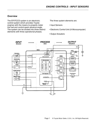
  • 1. Overview The EFl/TCCS system is an electronic control system which provides Toyota engines with the means to properly meter the fuel and control spark advance angle. The system can be divided into three distinct elements with three operational phases. The three system elements are: • Input Sensors • Electronic Control Unit (A Microcomputer) • Output Actuators ENGINE CONTROLS - INPUT SENSORS Page 1 © Toyota Motor Sales, U.S.A., Inc. All Rights Reserved.
  • 2. The electronic control system is responsible for monitoring and managing engine functions which were previously performed by mechanical devices like carburetors, vacuum, and centrifugal advance units. In an electronic control system, these functions are managed in three phases. • The input phase of electronic control allow the Electronic Control Unit (ECU) to monitor engine operating conditions, utilizing information from the input sensors. • The process phase of electronic control requires the ECU to use this input information to make operating decisions about the fuel and spark advance systems. • The output phase of electronic control requires the ECU to control the output actuators, the fuel injectors, and igniter to achieve the desired fuel metering and spark timing. In this chapter, we will explore the details of the electronic control system hardware and software. The chapter starts with a thorough examination of the system's input sensor circuits and the ECU power distribution system. It concludes with a closer look at the ECU process functions and the control strategy use( for optimum fuel metering and spark advance angle control. The Microcomputer The heart of the TCCS system is a microcomputer. A microcomputer is a device which receives information, processes it, and makes decisions based on a set of program instructions. The microcomputer exercises control over the output actuators to carry out these instructions. The use of microcomputers has taken the science of engine management into the space age by increasing the speed with which information can be processed and allowing the electronic control system to manage more engine functions. With the ability to process information so rapidly, the modern ECU is capable of carrying out its programmed instructions with extreme accuracy. Engine management can address virtually every condition the engine will encounter so that for any engine condition, the ECU will deliver optimum fuel and spark. Evolution of Toyota's Electronic Fuel Injection Systems Early Conventional EFI computers were first configured from analog circuits, and they controlled only fuel delivery and injection. The modem Electronic Control Units (ECU) utilize digital circuits and microprocessors which have served to improve EFI system capabilities. Modern TCCS engine controls, introduced to the U.S.A. market in 1983, are capable of managing fuel delivery, idle speed control (ISC), electronic spark advance (ESA), and emissions systems with extraordinary speed and accuracy. In the evolution of Toyota's fuel injection, three levels of electronic control refinements have taken place. • Conventional EFI • P7/EFI • EFI/TCCS The main difference between these systems is the capability of the ECU. These capabilities have grown from simple fuel control to the addition of self-diagnostics to the control of ignition spark advance and more. The following chart summarizes basic capabilities by system and can be used as a guide in identification and troubleshooting. ENGINE CONTROLS - INPUT SENSORS Page 2 © Toyota Motor Sales, U.S.A., Inc. All Rights Reserved.
  • 3. System identification is relatively simple. • The Conventional EFI system has no check engine light. • The P7/EFI system has a check engine light but has a mechanical advance distributor. • The EFI/TCCS system has a check engine light and an electronic advance distributor. The Input Sensors, Information Source for the ECU In an electronic control system, the ECU uses its sensors in much the same manner as we use our five senses. Our sense of touch tells us when things are hot or cold; our sense of hearing allows us to distinguish one sound from another; our sense of smell tells us when fresh coffee is brewing somewhere nearby. Sensors give the ECU similar abilities: the ability to feel the temperature of the engine coolant, to listen for the sound of detonation, and to smell the exhaust stream for the presence of sufficient oxygen. This lesson on input sensors will address how each major ECU input sensor circuit works. Each sensor circuit will be broken down so you can see its individual components: the sensor, electrical wiring, and the ECU. ENGINE CONTROLS - INPUT SENSORS Page 3 © Toyota Motor Sales, U.S.A., Inc. All Rights Reserved.
  • 4. Overview The EFl/TCCS system is an electronic control system which provides Toyota engines with the means to properly meter the fuel and control spark advance angle. The system can be divided into three distinct elements with three operational phases. The three system elements are: • Input Sensors • Electronic Control Unit (A Microcomputer) • Output Actuators ENGINE CONTROLS - INPUT SENSORS Page 4 © Toyota Motor Sales, U.S.A., Inc. All Rights Reserved.
  • 5. Input Sensors Used in Basic Injection and Spark Calculation Engine Air Flow Sensing Vane Type Air Flow Meters (Vs, General Information) The vane type air flow meter is located in the air induction system inlet pipe between the air cleaner and the throttle body. It is composed of the measuring plate, compensation plate, return spring, potentiometer, and by-pass passage. The sensor also incorporates the idle mixture adjusting screw (factory sealed), the fuel pump switch, and the intake air temperature sensor (which will be addressed later in this lesson). Because intake air volume is a direct measure of the load placed on an engine, the vane type air flow meter provides the most important input to the ECU for fuel and spark calculations. When air passes through the air flow meter, it forces the measuring plate open to a point where it balances with the force of the return spring. The damping chamber and compensation plate prevent vibration of the measuring plate during periods of sudden intake air volume changes. The potentiometer, which is connected to the measuring plate and rotates on the same axis, converts the mechanical movement of the measuring plate into a variable voltage signal. Movement of the measuring plate and the analog voltage signal produced by this sensor are proportional to the volume of air entering the intake manifold. Vane Air How Meter Electrical Circuit The sensor movable contact is attached to the measuring plate and rides on a fixed resistor wired between the reference voltage input and the ground. As the volume of air entering the engine increases, the movable contact moves across the fixed resistor, causing a change in signal output voltage. There are two designs of vane air flow meters used on Toyota L type EFI systems. The first design generates a signal which varies from low voltage at low air volumes to high voltage at high air volumes. The second design sensor has opposite signal characteristics. These sensors also operate on different reference voltages. Both sensor designs integrate an intake air temperature sensor into the air flow meter. ENGINE CONTROLS - INPUT SENSORS Page 5 © Toyota Motor Sales, U.S.A., Inc. All Rights Reserved.
  • 6. First Design Vane Air How Meter The first design air flow meter is found on all Conventional EFI engines and many later model TCCS equipped engines. This sensor has an electrical connector with seven terminals, four of which are used for air flow measurement. Air Flow Sensor Terminal Identification (First Design Sensor) The air flow meter and ECU are wired as shown in the diagram. Signal characteristics are depicted by the accompanying graph. The use of battery voltage, VB, as a sensor input necessitates the use of the Vc terminal as a constant reference signal for the ECU. This is because battery voltage may change with variances in electrical load and ambient temperatures. Without the use of a constant reference voltage, these changes would cause a change in the Vs signal value recognized by the ECU. ENGINE CONTROLS - INPUT SENSORS Page 6 © Toyota Motor Sales, U.S.A., Inc. All Rights Reserved.
  • 7. Second Design Air How Meter The second design air flow meter was introduced on the '85 5M-GE engine, and its use expanded with many late model TCCS equipped engines. This sensor has an electrical connector with seven terminals, three of which are used for air flow measurement. Air Flow Sensor Terminal Identification (Second Design Sensor) The air flow meter and ECU are wired as shown in the diagram; signal characteristics are depicted by the accompanying graph. The use of a regulated 5 volt reference eliminates the need for the VB terminal with this sensor circuit. Resistors R1 and R2 provide self diagnostic capabilities and allow for a fail-safe voltage at the ECU in the event of an open circuit. These two resistors have a very high resistance value (relative to r1 and r2) and essentially have no electrical effect on the circuit under normal operating conditions. They will, however, affect the open circuit voltage measured on the Vs wire at the ECU. ENGINE CONTROLS - INPUT SENSORS Page 7 © Toyota Motor Sales, U.S.A., Inc. All Rights Reserved.
  • 8. Karman Vortex Air Flow Meter (Ks) The Karman vortex air flow meter is currently used on the 7M-GTE Toyota engine and the 2JZ-GE and 1UZ-FE Lexus engines. It is located in the air induction system inlet pipe between the air cleaner and the throttle body. The sensor is composed of a photocoupler and mirror, a vortex generator, and an integrated circuit (IC) which together, measure the frequency of the vortices generated by air entering the intake system. When compared with the vane type air flow meter, the Karman vortex meter is smaller, lighter, and offers less restriction to incoming air. Similar to the vane type air meter, the Karman vortex meter integrates the intake air temperature sensor into the meter assembly. The sensor has an electrical connector with five terminals, three of which are used for air flow measurement. Karman Vortex Air Flow Meter Terminal Identification ENGINE CONTROLS - INPUT SENSORS Page 8 © Toyota Motor Sales, U.S.A., Inc. All Rights Reserved.
  • 9. The Karman vortex air flow meter and ECU are wired as shown in the diagram. Signal characteristics are represented by the illustration of the variable frequency square wave. Because of the pull-up resistor wired between the Vcc and Ks circuit, the Ks signal will go to 5 volts if the circuit is opened. When air passes through the air flow meter, the vortex generator creates a swirling of the air downstream. This swirling effect is referred to as a "Karman vortex." The frequency of this Karman vortex varies with the velocity of the air entering the air flow meter and other variables. The photocoupler and metal foil mirror are used to detect changes in these vortices. ENGINE CONTROLS - INPUT SENSORS Page 9 © Toyota Motor Sales, U.S.A., Inc. All Rights Reserved.
  • 10. The metal foil mirror is used to reflect light from the LED to the photo transistor. The foil is positioned directly above a pressure directing hole which causes it to oscillate with the changes in vortex frequency. As the mirror oscillates, the 5 volt Vcc reference is switched to ground by a photo transistor within the sensor. The resulting digital signal is a 5 volt square wave which increases in frequency in proportion to increases in intake air flow. ENGINE CONTROLS - INPUT SENSORS Page 10 © Toyota Motor Sales, U.S.A., Inc. All Rights Reserved.
  • 11. Manifold Absolute Pressure Sensor The manifold absolute pressure sensor (sometimes referred to as vacuum sensor) is used on engines equipped with D type EFI. It is typically located somewhere on the bulkhead with a vacuum line leading directly to the intake manifold. It measures intake air volume by monitoring changes in manifold absolute pressure, a function of engine load. The sensor consists of a piezoresistive silicon chip and an Integrated Circuit (IC). A perfect vacuum is applied to one side of the silicon chip and manifold pressure applied to the other side. When pressure in the intake manifold changes, the silicon chip flexes, causing a change in its resistance. The varying resistance of the sensor causes a change in signal voltage at the PIM (Pressure Intake Manifold) terminal. ENGINE CONTROLS - INPUT SENSORS Page 11 © Toyota Motor Sales, U.S.A., Inc. All Rights Reserved.
  • 12. The manifold absolute pressure sensor has an electrical connector with three terminals. Manifold Absolute Pressure Sensor Terminal Identification The sensor and ECU are wired as shown in the diagram. As manifold pressure increases (approaches atmospheric pressure) there is a proportionate increase in PIM signal voltage. This analog signal characteristic is depicted in the accompanying graph. TO check sensor calibration, signal voltage should be checked against the standards shown on the graph, and a voltage drop check should be performed over the entire operating range of the sensor. ENGINE CONTROLS - INPUT SENSORS Page 12 © Toyota Motor Sales, U.S.A., Inc. All Rights Reserved.
  • 13. Engine Speed and Crankshaft Angle Sensing On TCCS equipped engines, the Ne and G1 signals inform the ECU of engine rpm and crankshaft angle. This information, along with information from the air flow or manifold pressure sensor, allows the ECU to calculate the engine's basic operating load. Based on measured load, basic injection and spark advance angle can be accurately calculated. Ne Signal (Number of Engine Revolutions) The Ne signal generator consists of a pickup coil and toothed timing rotor. The number of teeth on the signal timing rotor is determined by the system used. The Ne sensor produces an alternating current waveform signal and is of critical importance to the ECU. If this signal fails to reach the ECU, the engine will not run. G or G1 Signal (Group #1) The G signal generator is very similar to the Ne signal generator. The G1 signal represents the standard crankshaft angle and is used by the ECU to determine ignition and injection timing in relation to TDC. Depending on engine, there are different variations of Ne and G1 signal generators. The following illustrations show the relationship between the Ne and G1 signals and the different variations of signal generators. ENGINE CONTROLS - INPUT SENSORS Page 13 © Toyota Motor Sales, U.S.A., Inc. All Rights Reserved.
  • 14. ENGINE CONTROLS - INPUT SENSORS Page 14 © Toyota Motor Sales, U.S.A., Inc. All Rights Reserved.
  • 15. lGf Signal The IGf signal is generated by the igniter on EFI/TCCS systems. The ECU supplies a 5 volt reference through a pull-up resistor to the lGf signal generation circuit in the igniter. When a spark plug fires, the IGf signal generation circuit pulls the five volts to ground, causing a pulse to be sensed at the ECU. One pulse is generated by the igniter for each ignition event which is carried out. IG Signal On Conventional EFI engines, the IG signal is used to inform the ECU of engine rpm. This signal is generated directly from the coil negative terminal or from an electrically equivalent point inside the igniter on the early The IGf signal confirms that ignition has actually occurred. In the event of a failure to trigger an ignition event, the ECU will shut down injector pulses to protect the catalyst from flooding with raw fuel. Typically this fail- safe shutdown occurs within eight to eleven IGt signals after the IGf signal is lost. This condition can occur with any primary ignition system fault, an igniter failure, a problem with the IGf circuit wiring, or with a faulty ECU. P-7 2S-E engine. Conventional EFI engines do not use an Ne or G sensor and do not use an IGf signal. The IG signal is also used by the ECU to trigger injection pulses; therefore, if this signal is lost, the engine will stall for lack of injection pulse. ENGINE CONTROLS - INPUT SENSORS Page 15 © Toyota Motor Sales, U.S.A., Inc. All Rights Reserved.
  • 16. Input Sensors Used For Injection and Spark Corrections Water Temperature Sensor (THW) The water temperature sensor is typically located near the cylinder head water outlet. It monitors engine coolant temperature by means of an internally mounted thermistor. The thermistor has a negative temperature coefficient (NTC), so its resistance value decreases as coolant temperature rises. The accompanying resistance graph demonstrates this relationship. The water temperature sensor is required because fuel vaporization is less efficient when the engine is cold. Internal engine friction is also higher during cold operation, increasing operating load. The THW signal is used by the ECU to determine how much fuel enrichment correction is necessary to provide good cold engine performance. In addition to fuel calculations, the THW signal plays a major role is almost every other function that the ECU serves. ENGINE CONTROLS - INPUT SENSORS Page 16 © Toyota Motor Sales, U.S.A., Inc. All Rights Reserved.
  • 17. The water temperature sensor has a two terminal electrical connector attached to either end of the thermistor element. Water Temperature Sensor Terminal Identification The sensor and ECU are wired as shown in the diagram. Signal voltage characteristics are determined by the value of the pull-up resistor, located inside the ECU, either 2.7 KΩ or 5 M. The graphs accompanying the diagram give approximate voltage specifications. To determine which pull-up resistor a particular ECU uses, refer to the technical reference charts in Appendix B of this book. ENGINE CONTROLS - INPUT SENSORS Page 17 © Toyota Motor Sales, U.S.A., Inc. All Rights Reserved.
  • 18. Air Temperature Sensor (THA) The air temperature sensor monitors the temperature of air entering the intake manifold by means of a thermistor. This thermistor is integrated within the air flow meter on L type systems and located in the intake air hose just downstream of the air cleaner on D type systems. It has the same resistance characteristics as the water temperature sensor. ENGINE CONTROLS - INPUT SENSORS Page 18 © Toyota Motor Sales, U.S.A., Inc. All Rights Reserved.
  • 19. This sensor has a two-terminal electrical connector attached to either end of the thermistor element. Air Temperature Sensor Terminal Identification The air temperature sensor and ECU are wired as shown in the diagram. Resistance and voltage signal characteristics are represented by the accompanying graphs. An intake air temperature monitor is necessary in the EFI system because the pressure and density of air changes with temperature. Because air is more dense when cold, the ECU factors intake air temperature into the fuel correction program. ENGINE CONTROLS - INPUT SENSORS Page 19 © Toyota Motor Sales, U.S.A., Inc. All Rights Reserved.
  • 20. Throttle Angle and Closed Throttle Sensing Throttle position sensors typically mount on the throttle body, directly to the end of the throttle shaft. Depending on engine and model year, Toyota EFI equipped engines use one of two different types of throttle position sensors. These sensors are categorized as on-off type and linear type. The linear type sensor is typically used on most late model Electronically Controlled Transmission (ECT) equipped vehicles. The on-off type sensor circuits can be further broken down into first and second design. This sensor is typically used on manual or non-ECT transmission equipped applications. All throttle sensors, regardless of design, supply the ECU with vital information about idle status and driver demand. This information is used by the ECU to make judgments about power enrichment, deceleration fuel cut-off, idle stability, and spark advance angle corrections. ENGINE CONTROLS - INPUT SENSORS Page 20 © Toyota Motor Sales, U.S.A., Inc. All Rights Reserved.
  • 21. On-Off Type Throttle Position Sensors (IDL & PSW) The on-off type throttle position sensor is a simple switch device which, depending on application, either pulls a reference voltage to ground or sends a battery voltage signal to the ECU. The on-off throttle position sensors are electrically wired to the ECU as shown in the accompanying diagrams. First Design On-Off Type Sensor The first design sensor is used on Conventional EFI engines. It utilizes a dual position contact which switches a battery voltage signal to either the IDL or PSW inputs at the ECU. This switching action causes the voltage signal at the ECU to go high whenever the switch contacts are closed. Referring to the voltage graph, IDL signal voltage is high when the throttle is closed and goes low when the throttle exceeds a 1.5' opening. PSW voltage is low until the throttle exceeds about a 70' opening; then it goes high. ENGINE CONTROLS - INPUT SENSORS Page 21 © Toyota Motor Sales, U.S.A., Inc. All Rights Reserved.
  • 22. Second Design On-Off Type Sensor The second design sensor, which is used on many late model TCCS equipped engines, utilizes a dual position contact to switch an ECU reference voltage to ground. This switching action causes the signal at the ECU to go low whenever the switch contacts are closed. Referring to the voltage graph, IDL signal voltage is low when the throttle is closed and goes high when the throttle exceeds a 1.5' opening. PSW voltage is high until the throttle opens to about 70’; then it goes low. The three wire electrical connector terminals are identified as follows. 1 st and 2nd Design On-Off Throttle Position Sensor Terminal Identification ENGINE CONTROLS - INPUT SENSORS Page 22 © Toyota Motor Sales, U.S.A., Inc. All Rights Reserved.
  • 23. On '83 and '84 Cressidas/Supras and '83 through '86 Camrys equipped with an Electronically Controlled Transmission (ECT), a modified sensor, which incorporates three additional signal wires designated L1, L2, and L3, is used. These signals represent throttle opening angles in between the 1.5' IDL and 70' PSW signals. The L1, L2, and L3 signals are used by the ECT system and are generated in a similar manner as the IDL and PSW signals on the 2nd design sensor. The TCCS ECU only uses the IDL and PSW signals from this sensor. Linear Throttle Position Sensor (VTA) The linear throttle position sensor is mounted to the throttle body. It is composed of two movable contacts, a fixed resistor, and four electrical terminals. The two movable contacts move along the same axis as the throttle valve. One is used for the throttle opening angle signal (VTA) and the other for the closed throttle signal (IDL). ENGINE CONTROLS - INPUT SENSORS Page 23 © Toyota Motor Sales, U.S.A., Inc. All Rights Reserved.
  • 24. As the throttle opens, a potentiometer circuit converts the mechanical movement of the throttle valve into a variable voltage signal. The voltage produced by this sensor is proportional to the throttle valve opening angle. The Linear Throttle Position Sensor has an electrical connector with four terminals. Linear Throttle Position Sensor Terminal Identification The sensor and ECU are wired as shown in the diagram. As the throttle valve opens, the sensor VTA contact moves closer to the voltage source, causing a signal voltage increase. At closed throttle, the IDL contact is held closed. This pulls the IDL signal circuit to ground. As the throttle opens, the IDL contact breaks, causing the digital IDL signal voltage to go from low to high. These signal characteristics are depicted in the accompanying graph. Resistors R1 and R2 provide self diagnostic capabilities and allow for a fail-safe voltage at the ECU in the event of an open circuit. These two resistors have a very high resistance value and essentially have no electrical effect on the circuit under normal operating conditions. They will, however, affect the open circuit voltage measured on the VTA wire at the ECU. ENGINE CONTROLS - INPUT SENSORS Page 24 © Toyota Motor Sales, U.S.A., Inc. All Rights Reserved.
  • 25. Exhaust Oxygen Content Sensing (OX1) Exhaust oxygen sensors are used on Toyota EFI and EFI/TCCS equipped engines to provide air/fuel ratio feedback information to the ECU. This information is used to constantly adjust the air/fuel ratio to stoichiometry during warm idle and cruise operating conditions. The stoichiometric air/fuel ratio delivers one pound of fuel for each 14.7 pounds of air entering the intake manifold and results in the most efficient combustion and catalyst operation. When the electronic control system is using information from the oxygen sensor to adjust air/fuel ratio, the system is said to be operating in closed loop. Exhaust oxygen sensor efficiency is dependent upon its operating temperature. The sensor will only generate an accurate signal when it has reached its minimum operating temperature of 750'F. Therefore, the oxygen sensor is typically located in the exhaust stream at the manifold collector. This location is close enough to the exhaust valves to maintain adequate operating temperature under most driving conditions and allows a representative exhaust sample from all cylinders. Open and Closed Loop Operation In addition to promoting efficient combustion and catalyst operation, a stoichiometric air/fuel ratio also promotes excellent fuel economy. This relatively lean mixture is desirable during cruise and idle operation; however, other operating conditions often require a richer air/fuel ratio. When the electronic control system ignores signals from the oxygen sensor and does not correct the air/fuel ratio to 14.7:1, the system is said to be operating in open loop. In order to prevent overheating of the catalyst and ensure good driveability, open loop operation is required under the following conditions: • During engine starting • During cold engine operation • During moderate to heavy load operation • During acceleration and deceleration During open loop operation, the ECU ignores information from the exhaust oxygen sensor and bases fuel injection duration calculations exclusively on the other input sensors. ENGINE CONTROLS - INPUT SENSORS Page 25 © Toyota Motor Sales, U.S.A., Inc. All Rights Reserved.
  • 26. Exhaust Oxygen Sensors Toyota engines utilize two different types of oxygen sensors. The zirconium dioxide sensor is used on all engines except the '90 and later 4A-GE Federal and 3VZ-E California 2WD truck engines. These two engines use a titania oxide sensor. To bring the system to closed loop operation more rapidly, many engines use a heated exhaust oxygen sensor. The heated sensor provides more accurate exhaust sampling during idle and low speed operation when exhaust temperatures are relatively low. Use of a heated sensor allows closed loop operation earlier during engine warm- up cycles and also allows more flexibility in oxygen sensor location. These factors help in meeting strict exhaust emissions control standards. Engines produced for sale in California also incorporate a Sub-Oxygen Sensor which helps improve the efficiency of the catalyst system. This sensor is located after the catalyst and is used to fine tune the air/fuel ratio delivered by the injectors, helping to optimize catalyst efficiency. Zirconium Dioxide Sensor The zirconium dioxide oxygen sensor is an electro-chemical device which compares the oxygen content of the exhaust stream with the oxygen in an ambient air sample. It consists of a zirconium dioxide (Zr02) element sandwiched between two platinum electrodes. This sensor behaves very similar to a single cell battery. The electrodes act as the positive (+) and negative (-) plates, and the zirconium dioxide element acts as the electrolyte. Rich air/fuel ratio: If the oxygen concentration on the inside plate differs greatly from that on the outside plate, as it would with a rich air/fuel ratio, electrons will flow through the Zr02 element to the plate exposed to the high oxygen concentration. During rich operating conditions, the inside, or positive plate, is exposed to a much higher concentration of oxygen than the outside, or negative plate. This creates a difference in electrical potential, or voltage, which is measured by a comparator circuit in the E CU. Lean air/fuel ratio: When the air/fuel ratio becomes lean, the oxygen content of the exhaust gas increases significantly. Because both plates are now exposed to a relatively high concentration of oxygen, electrons balance equally between the two plates. This eliminates the electrical potential between the plates. Zirconium Dioxide Oxygen Sensor Operating Characteristics ENGINE CONTROLS - INPUT SENSORS Page 26 © Toyota Motor Sales, U.S.A., Inc. All Rights Reserved.
  • 27. Zr02 sensor voltage signal and ECU processing: The voltage signal produced by. the oxygen sensor is relatively small. During the richest operating conditions, this signal approaches 1000 millivolts (1 volt). The Zr02 oxygen sensor is wired as shown in the diagram. Voltage characteristics are depicted in the accompanying graph. As the voltage graph illustrates, the output of the Zr02 sensor acts almost like a switch. As the air/fuel ratio passes through the stoichiometric range, voltage rapidly switches from high to low. The ECU comparator circuit is designed to monitor the voltage from the sensor and send a digital signal to the microprocessor. If sensor voltage is above the comparator switch point, z 1/2 volt, the comparator output will be high. If the sensor voltage is below the comparator switch point, the comparator output will be low. The microcomputer monitors the output of the comparator to determine how much oxygen remains in the exhaust stream after combustion occurs. ENGINE CONTROLS - INPUT SENSORS Page 27 © Toyota Motor Sales, U.S.A., Inc. All Rights Reserved.
  • 28. Titania Oxide Sensor This four-terminal device is a variable resistance sensor with heater. It is connected in series between the OX+ reference and a fixed resistance located inside the ECU. This circuit operates similarly to a thermistor circuit. The properties of the thick film titania element are such that as oxygen concentration of the exhaust gas changes, the resistance of the sensor changes. As the sensor resistance changes, the signal voltage at the ECU also changes. TITANIA OXIDE SENSOR RESISTANCE CHARACTERISTICS The titania sensor and ECU are wired as shown in the diagram. A one-volt potential is supplied at all times to the OX+ terminal of the sensor. The resistance value of the sensor changes abruptly as the stoichiometric boundary is crossed. The accompanying voltage and resistance graphs depict these characteristics and their influence on OX signal voltage. The ECU comparator circuit is designed to monitor the voltage drop across R1. As the voltage drop across the sensor increases, the drop across R1 decreases and vice versa. This gives the OX signal voltage the same characteristic as the Zr02 sensor. If sensor voltage drop is low, as it would be with a rich mixture, OX signal voltage will be above the comparator switch point, 450 millivolts, and the comparator output will be high. If the sensor voltage drop is high, OX signal voltage will be below the comparator switch point and the comparator output will be low. ENGINE CONTROLS - INPUT SENSORS Page 28 © Toyota Motor Sales, U.S.A., Inc. All Rights Reserved.
  • 29. Sub-Oxygen Sensor (OX2) The sub-oxygen sensor is used on California and some Federal engines. It is used to monitor the exhaust stream after the catalyst to determine if the air/fuel mixture is within the range for efficient converter operation. The sub-oxygen sensor is identical to the Zr02 main oxygen sensor located ahead of the catalyst. Information from this sensor is used by the ECU to fine tune the air/fuel ratio and improve emissions. ENGINE CONTROLS - INPUT SENSORS Page 29 © Toyota Motor Sales, U.S.A., Inc. All Rights Reserved.
  • 30. Oxygen Sensor Heater Circuits (HT) Oxygen sensors work very efficiently when the sensing element temperature is above 750'F (400'C). At warm cruise, it is not difficult to maintain oxygen sensor temperatures at or above this point. However, when the engine is first started or when idling or when driving under very light load, the oxygen sensor can cool down, forcing the fuel system to return to open loop operation. The oxygen sensor heater control system maintains sensor accuracy by turning on the heater element whenever intake air volume is low (exhaust temperatures are low under these conditions). By heating the sensor electrically, sensor detection performance is enhanced. This allows feedback operation under conditions which might otherwise require open loop fuel control. The ECU monitors the following parameters and cycles the oxygen sensor heater on: • When intake air flow is below a given point. and • coolant temperature is above approximately 32'F (O'C). • specified time has elapsed after starting. The oxygen sensor heater and ECU are wired as shown in the diagram. Whenever the above mentioned conditions are met, the ECU turns on the driver transistor to supply a ground path for heater current. ENGINE CONTROLS - INPUT SENSORS Page 30 © Toyota Motor Sales, U.S.A., Inc. All Rights Reserved.
  • 31. Other Inputs Affecting Injection and Spark Correction Engine Cranking Signal (STA) STA is a digital signal which is used by the ECU to determine if the engine is being cranked. The signal is generated at the ST1 terminal of the ignition switch and is used by the ECU primarily to increase fuel injection volume during cranking. The STA circuit is wired to the ECU as shown in the diagram. The ECU will sense cranking voltage at the STA terminal whenever the ignition is switched to the "start" position as long as the neutral or clutch switch is closed. ENGINE CONTROLS - INPUT SENSORS Page 31 © Toyota Motor Sales, U.S.A., Inc. All Rights Reserved.
  • 32. Engine Detonation (Knock) Signal (KNK) Knock Sensor The knock sensor is a piezoelectric device mounted to the cylinder block which generates a voltage whenever it is exposed to vibration. When engine detonation occurs, vibration of the cylinder block causes the sensor to generate a voltage signal. The sensor signal varies in amplitude depending on the intensity of knock. Typically, detonation vibration occurs in the 7KHz range (7 thousand cycles per second). Knock sensor and ECU designs take advantage of this fact. There are two different types of knock sensors used on Toyota engines. The mass type sensor produces a voltage output over a wide input frequency range; however, its signal output is greatest at a vibration frequency of approximately 7KHz. With this type of sensor, the ECU uses a filter circuit to distinguish between background noise and actual engine knock. The resonance type sensor is tuned into a very narrow frequency band and only produces a significant signal voltage when exposed to vibrations in the 7KHz range. The ECU requires less complicated filter circuitry with this type of sensor. ECU Detonation Control The ECU and knock sensor are wired as shown in the diagram. When engine detonation occurs, the ECU monitors knock sensor signal feedback to determine the degree of detonation taking place. This is accomplished by filtering out sensor signal voltage which does not go above preprogrammed amplitude parameters. Because other background noise and vibration cause some signal output from the knock sensor, the ECU is also programmed to filter out any signal which does not fall within certain frequency ranges. When the ECU judges that detonation is taking place, it retards ignition timing until the knocking stops. Timing is then advanced back to calculated value or, if detonation again begins, retarded again until detonation is stopped. In this manner, the ignition system can be operated at maximum efficiency, on the borderline of detonation, while avoiding an audible "ping." In the event that the ECU continues to sense detonation, timing retard is limited based on a clamp value stored in memory. If the ECU determines that the knock retard is not functional, it will enter a fail-safe mode and fix the retard angle to prevent engine damage. ENGINE CONTROLS - INPUT SENSORS Page 32 © Toyota Motor Sales, U.S.A., Inc. All Rights Reserved.
  • 33. Altitude Sensing (HAC) Some TCCS equipped engines like the 3F-E, 3VZ-E (Cab and Chassis), and the 7M-GTE incorporate an altitude sensor in the TCCS system to shorten injection duration when the vehicle is operated at higher altitudes. Because the density of oxygen in the atmosphere is lower at high altitudes, the air volume measured by the air flow meter will not accurately represent actual oxygen entering the engine. This would result in a mixture which is excessively rich, causing emissions and driveability concerns. The HAC sensor is integrated with the ECU on the 3-FE, 3VZ-E, and 1989 and later 7M- GTE engines. It is remotely mounted behind the glove box on the '87 and '88 7M-GTE Supra. The remotely mounted HAC sensor is wired to the ECU exactly the same as the manifold pressure sensor is wired on D type EFI. In fact, the HAC sensor circuit is electrically the same as a manifold pressure sensor circuit. The HAC sensor simply measures atmospheric pressure rather than intake manifold pressure. The signal from the HAC circuit in the ECU is used to determine the fuel correction coefficient to be used after basic injection has been calculated. The accompanying graph represents how this correction factor affects final injection duration. ENGINE CONTROLS - INPUT SENSORS Page 33 © Toyota Motor Sales, U.S.A., Inc. All Rights Reserved.
  • 34. Stop Light Switch (STP) The stop light switch input to the ECU is used to modify the deceleration fuel cut program when the vehicle is braking. Whenever the STIR signal is high (brake pedal is depressed), fuel cutoff and resumption rpm is reduced to improve driveability characteristics of the vehicle. In the event the STP signal is lost, fuel cut will take place at the standard deceleration speed, causing an objectionable feel when fuel is canceled. The STP signal at the ECU will be low as long as the brake pedal is not applied. When the pedal is depressed, current flows through the normally open stop light switch to the stop lamps and the ECU, causing the STP voltage to go high. ENGINE CONTROLS - INPUT SENSORS Page 34 © Toyota Motor Sales, U.S.A., Inc. All Rights Reserved.