SlideShare une entreprise Scribd logo
1  sur  33
Crystal Structure
Crystal Structure
A crystal structure is defined as the particular repeating arrangement
of atoms (molecules or ions) throughout a crystal. Structure refers to
the internal arrangement of particles and not the external appearance
of the crystal.
Bravais lattice
The Bravais lattice is the basic building block from which all
crystals can be constructed. Each point would be surrounded by an
identical set of points as any other point, so that all points would be
indistinguishable from each other. Mathematician Auguste Bravais
discovered that there were 14 different collections of the groups of
points, which are known as Bravais lattices. These lattices fall into
seven different "crystal systems”, as differentiated by the
relationship between the angles between sides of the “unit cell” and
the distance between points in the unit cell.
Unit Cell
The unit cell is the smallest group of atoms, ions or molecules
that, when repeated at regular intervals in three dimensions,
will produce the lattice of a crystal system. The “lattice
parameter” is the length between two points on the corners of a
unit cell. Each of the various lattice parameters are designated
by the letters a, b, and c. If two sides are equal, such as in a
tetragonal lattice, then the lengths of the two lattice parameters
are designated a and c, with b omitted. The angles are
designated by the Greek letters α, β, and γ, such that an angle
with a specific Greek letter is not subtended by the axis with its
Roman equivalent. For example, α is the included angle
between the band c axis.
System Axial lengths and angles Unit cell geometry
cubic a = b = c, α = β = γ= 90°
tetragonal a = b ≠ c, α = β = γ= 90°
orthorhombic a ≠ b ≠ c, α = β = γ= 90°
rhombohedral a = b = c, α = β = γ ≠ 90°
hexagonal
a = b ≠ c, α = β = 90°, γ =
120°
monoclinic a ≠ b ≠ c, α = γ = 90°, β ≠ 90°
triclinic a ≠ b ≠ c, α ≠ β ≠ γ
TABLE 1: Geometrical characteristics of the seven crystal systems.
Shared by 8 unit cells Shared by 2 unit cells
1 atom/unit cell
(8 x 1/8 = 1)
2 atoms/unit cell
(8 x 1/8 + 1 = 2)
4 atoms/unit cell
(8 x 1/8 + 6 x 1/2 = 4)
Atom positions, crystal directions and Miller indices
The structure of a crystal is defined with respect to a unit cell. As the entire crystal consists
of repeating unit cells, this definition is sufficient to represent the entire crystal. Within the
unit cell, the atomic arrangement is expressed using coordinates. For example, consider a
cubic cell of dimension 3.52 Å. Pretend that this cell contains an atom that has the
coordinates (1.5, 2.1, 2.4). That is, the atom is 1.5 Å away from the origin in the x direction
(which coincides with the a cell axis), 2.1 Å in the y (which coincides with the b cell axis) and
2.4 Å in the z (which coincides with the c cell axis). There will be an equivalent atom in the
next unit cell along the x-direction, which will have the coordinates (1.5 + 3.52, 2.1, 2.4) or
(5.02, 2.1, 2.4). This was a rather simple calculation, as the cell has very high symmetry and
so the cell axes, a, b and c, coincide with the Cartesian axes, X, Y and Z. Accordingly, atomic
coordinates are usually expressed in terms of fractional coordinates, (x, y, z). This
coordinate system is coincident with the cell axes (a, b, c) and relates to the position of the
atom in terms of the fraction along each axis. Consider the atom in the cubic cell discussion
above. The atom was 1.5 Å in the a direction away from the origin. As the a axis is 3.52 Å
long, the atom is (1.5/3.52) or 0.43 of the axis away from the origin. Similarly, it is (2.1/3.52) or
0.60 of the b axis and (2.4/3.5) or 0.68 of the c axis. The fractional coordinates of this atom
are, therefore, (0.43, 0.60, 0.68). The coordinates of the equivalent atom in the next cell over
in the a direction, however, are easily calculated as this atom is simply 1 unit cell away in a.
Thus, all one has to do is add 1 to the x coordinate: (1.43, 0.60, 0.68). Such transformations
can be performed regardless of the shape of the unit cell. Fractional coordinates, therefore,
are used to retain and manipulate crystal information.
Miller Indices (hkl)
Miller indices are a notation system in crystallography for planes
and directions in crystal (Bravais) lattices.
The orientation of a surface or a crystal plane may be defined by
considering how the plane (or indeed any parallel plane) intersects
the main crystallographic axes of the solid. The application of a set
of rules leads to the assignment of the Miller Indices , (hkl) ; A set
of numbers which quantify the intercepts and thus may be used to
uniquely identify the plane or surface.
The designation of the individual vectors within any given crystal
lattice is indicated by the notation [hkl], where h, k, and l are
reciprocals of the point at which the vector exits the unit cell. The
origination of all vectors is assumed defined as [000]. For example,
the direction along the a-axis according to this scheme would be
[100] because this has a component only in the a-direction and no
component along either the b or c axial direction.
Miller Indices are a symbolic vector representation for the orientation of an
atomic plane in a crystal lattice and are defined as the reciprocals of the
fractional intercepts which the plane makes with the crystallographic axes.
A vector diagonally along the face defined by the a and b axis would be
[110], while going from one corner of the unit cell to the opposite
corner would be in the [111] direction.
Figure 2 shows some examples of the various directions in the unit cell.
The crystal direction notation is made up of the lowest combination of
integers and represents unit distances rather than actual distances. A
[222] direction is identical to a [111], so [111] is used. Fractions are not
used. For example, a vector that intercepts the center of the top face of
the unit cell has the coordinates x = 1/2, y = 1/2, z = 1. All have to be
inversed to convert to the lowest combination of integers (whole
numbers); i.e., [221] in Figure 2. Finally, all parallel vectors have the
same crystal direction, e.g., the four vertical edges of the cell shown
in Figure 2 all have the crystal direction [hkl] = [001].
Crystal directions may be grouped in families. To avoid confusion
there exists a convention in the choice of brackets surrounding the
three numbers to differentiate a crystal direction from a family of
direction. For a direction, square brackets [hkl] are used to
indicate an individual direction. Angle brackets <hkl> indicate a
family of directions. A family of directions includes any directions
that are equivalent in length and types of atoms encountered. For
example, in a cubic lattice, the [100], [010], and [001] directions
all belong to the <100> family of planes because they are
equivalent. If the cubic lattice were rotated 90°, the a, b,
and c directions would remain indistinguishable, and there would
be no way of telling on which crystallographic positions the atoms
are situated, so the family of directions is the same. In a hexagonal
crystal, however, this is not the case, so the [100] and [010] would
both be <100> directions, but the [001] direction would be
distinct. Finally, negative directions are identified with a bar over
the negative number instead of a minus sign.
Crystal directions
Figure 2
Planes in a crystal can be specified using a notation called Miller
indices. The Miller index is indicated by the notation [hkl]
where h, k, and l are reciprocals of the plane with the x, y,
and z axes. To obtain the Miller indices of a given plane requires
the following steps:
Step 1. The plane in question is placed on a unit cell.
Step 2. Its intercepts with each of the crystal axes are then
found.
Step 3. The reciprocal of the intercepts are taken.
Step 4. These are multiplied by a scalar to insure that is in the
simple ratio of whole numbers.
For example, the face of a lattice that does not intersect the y or z
axis would be (100), while a plane along the body diagonal would
be the (111) plane. An illustration of this along with the (111) and
(110) planes is given in Figure 3.
Crystal Planes & Miller Indices
Figure 3
Description of Crystal Structure
1. The size and shape of the unit cell
2. Positions of the atoms (or ions) within the cell
However, this information is sometimes insufficient to allow for an
understanding of the true structure in three dimensions. Consideration
of several unit cells, the arrangement of the atoms with respect to each
other, the number of other atoms they in contact with, and the
distances to neighboring atoms, often will provide a better
understanding.
Close packed structures: hexagonal close packing and cubic close packing
In geometry, close-packing of spheres is a dense arrangement of equal spheres in
an infinite, regular arrangement (or lattice). The highest average density – that is,
the greatest fraction of space occupied by spheres – that can be achieved by a
regular lattice arrangement is 0.74048. The packing efficiency (volume of space
occupied by the spheres/total volume) is 74.05 % for both cubic and hexagonal
close packing schemes.
Within the square packed layer the coordination # of each atom is 4, in the
close packed layer it is 6.
Square Packed Layer Close packed array.
FCC and HCP lattices
There are two simple regular lattices that achieve this highest average
density. They are called face-centered cubic (fcc) (also called cubic close
packed) and hexagonal close-packed (hcp), based on their symmetry. Both
are based upon sheets of spheres arranged at the vertices of a triangular tiling;
they differ in how the sheets are stacked upon one another.
A single layer of spheres is closest-packed with HEXAGONAL coordination
of each sphere
A second layer of spheres is placed in the indentations left by the first layer
space is trapped between the layers that is not filled by the spheres
TWO different types of HOLES (so-called INTERSTITIAL sites) are left
OCTAHEDRAL (O) holes with 6 nearest sphere neighbours
TETRAHEDRAL (T±) holes with 4 nearest sphere neighbours
When a third layer of spheres is placed in the indentations of the second layer
there are TWO choices
The third layer lies in indentations directly in line (eclipsed) with the 1st layer.
Layer ordering may be described as ABA
The third layer lies in the alternative indentations leaving it staggered with
respect to both previous layers. Layer ordering may be described as ABC
Figure : Schematic representation of the three close packed layers in a cubic
close packed arrangement: A (dark grey), B (medium grey), and C (light grey).
If two close packed layers A and B are placed in contact with each
other so as to maximize the density, then the spheres of layer B will
rest in the hollow (vacancy) between three of the spheres in layer A.
This is demonstrated in Figure. Atoms in the second layer, B (shaded
light gray), may occupy one of two possible positions (Figure a or b)
but not both together or a mixture of each. If a third layer is placed on
top of layer B such that it exactly covers layer A, subsequent
placement of layers will result in the following sequence
...ABABAB.... This is known as hexagonal close packing or hcp.
Octahedral and tetrahedral vacancies
As was mentioned above, the packing fraction in both fcc and hcp cells is
74.05%, leaving 25.95% of the volume unfilled. The unfilled lattice sites
(interstices) between the atoms in a cell are called interstitial sites or
vacancies. The shape and relative size of these sites is important in
controlling the position of additional atoms. In both fcc and hcp cells most
of the space within these atoms lies within two different sites known as
octahedral sites and tetrahedral sites. The difference between the two lies in
their “coordination number”, or the number of atoms surrounding each site.
Tetrahedral sites (vacancies) are surrounded by four atoms arranged at the
corners of a tetrahedron. Similarly, octahedral sites are surrounded by six
atoms which make-up the apices of an octahedron. For a given close
packed lattice an octahedral vacancy will be larger than a tetrahedral
vacancy.
Within a face centered cubic lattice, the eight tetrahedral sites are positioned
within the cell, at the general fractional coordinate of (n/4,n/4,n/4) where n = 1 or 3,
e.g., (1/4,1/4,1/4), (1/4,1/4,3/4), etc. The octahedral sites are located at the center of
the unit cell (1/2,1/2,1/2), as well as at each of the edges of the cell, e.g., (1/2,0,0). In
the hexagonal close packed system, the tetrahedral sites are at (0,0,3/8) and
(1/3,2/3,7/8), and the octahedral sites are at (1/3,1/3,1/4) and all symmetry equivalent
positions.
Diamond Cubic Structure
The diamond cubic structure consists of two
interpenetrating face-centered cubic lattices,
with one offset 1/4 of a cube along the cube
diagonal. It may also be described as face
centered cubic lattice in which half of the
tetrahedral sites are filled while all the
octahedral sites remain vacant. The diamond
cubic unit cell is shown in Figure . Each of the
atoms (e.g., C) is four coordinate, and the
shortest interatomic distance (C-C) may be
determined from the unit cell parameter (a).
Figure : Unit cell structure of a
diamond cubic lattice showing the
two interpenetrating face-centered
cubic lattices.
Zinc blende
As with the diamond lattice, zinc blende
consists of the two
interpenetrating fcc lattices. However, in zinc
blende one lattice consists of one of the types
of atoms (Zn in ZnS), and the other lattice is
of the second type of atom (S in ZnS). It may
also be described as face centered cubic
lattice of S atoms in which half of the
tetrahedral sites are filled with Zn atoms. All
the atoms in a zinc blende structure are 4-
coordinate. The zinc blende unit cell is shown
in Figure. A number of inter-atomic distances
may be calculated for any material with a zinc
blende unit cell using the lattice parameter
(a).
Figure : Unit cell structure of a
zinc blende (ZnS) lattice. Zinc
atoms are shown in green
(small), sulfur atoms shown in
red (large), and the dashed lines
show the unit cell.
Rock salt
As its name implies the archetypal rock salt
structure is NaCl (table salt). In common with
the zinc blende structure, rock salt consists of
two interpenetrating face-centered cubic
lattices. However, the second lattice is offset
1/2aalong the unit cell axis. It may also be
described as face centered cubic lattice in
which all of the octahedral sites are filled,
while all the tetrahedral sites remain vacant,
and thus each of the atoms in the rock salt
structure are 6-coordinate. The rock salt unit
cell is shown in Figure. A number of inter-
atomic distances may be calculated for any
material with a rock salt structure using the
lattice parameter (a).
Figure : Unit cell structure of a
rock salt lattice. Sodium ions
are shown in purple (small
spheres) and chloride ions are
shown in red (large spheres).
Cesium Chloride
The cesium chloride structure is found
in materials with large cations and
relatively small anions. It has a simple
(primitive) cubic cell (Figure ) with a
chloride ion at the corners of the cube
and the cesium ion at the body center.
The coordination numbers of both
Cs+ and Cl-, with the inner atomic
distances determined from the cell
lattice constant (a).
THANK YOU
Made By:
Anita Malviya

Contenu connexe

Tendances (20)

Crystal structure
Crystal structureCrystal structure
Crystal structure
 
Structure of Crystal Lattice - K Adithi Prabhu
Structure of Crystal Lattice - K Adithi PrabhuStructure of Crystal Lattice - K Adithi Prabhu
Structure of Crystal Lattice - K Adithi Prabhu
 
Symmetry
SymmetrySymmetry
Symmetry
 
Bravais lattices
Bravais latticesBravais lattices
Bravais lattices
 
Solid State
Solid StateSolid State
Solid State
 
CRYSTAL STRUCTURE AND ITS TYPES-SOLID STATE PHYSICS
CRYSTAL STRUCTURE AND ITS TYPES-SOLID STATE PHYSICSCRYSTAL STRUCTURE AND ITS TYPES-SOLID STATE PHYSICS
CRYSTAL STRUCTURE AND ITS TYPES-SOLID STATE PHYSICS
 
Crystal stmmetry
Crystal stmmetryCrystal stmmetry
Crystal stmmetry
 
crystalstructure
crystalstructurecrystalstructure
crystalstructure
 
Miller indices
Miller indicesMiller indices
Miller indices
 
Crystalography
CrystalographyCrystalography
Crystalography
 
Crystallographic planes
Crystallographic planesCrystallographic planes
Crystallographic planes
 
Crystal systems
Crystal systemsCrystal systems
Crystal systems
 
Brillouin zone and wigner seitz cell
Brillouin zone and wigner  seitz cellBrillouin zone and wigner  seitz cell
Brillouin zone and wigner seitz cell
 
Crystal Physics
Crystal PhysicsCrystal Physics
Crystal Physics
 
Crystal structure
Crystal structureCrystal structure
Crystal structure
 
Unit i-crystal structure
Unit i-crystal structureUnit i-crystal structure
Unit i-crystal structure
 
Miller indecies
Miller indeciesMiller indecies
Miller indecies
 
Solid state chemistry
Solid state chemistrySolid state chemistry
Solid state chemistry
 
UCSD NANO106 - 03 - Lattice Directions and Planes, Reciprocal Lattice and Coo...
UCSD NANO106 - 03 - Lattice Directions and Planes, Reciprocal Lattice and Coo...UCSD NANO106 - 03 - Lattice Directions and Planes, Reciprocal Lattice and Coo...
UCSD NANO106 - 03 - Lattice Directions and Planes, Reciprocal Lattice and Coo...
 
Close packing and voids
Close packing and voidsClose packing and voids
Close packing and voids
 

Similaire à Crystal Structure

Solid state physics by Dr. kamal Devlal.pdf
Solid state physics by Dr. kamal Devlal.pdfSolid state physics by Dr. kamal Devlal.pdf
Solid state physics by Dr. kamal Devlal.pdfUMAIRALI629912
 
Solid state physics unit 1.pdf
Solid state physics unit 1.pdfSolid state physics unit 1.pdf
Solid state physics unit 1.pdfshadreckalmando
 
Crystallographic planes and directions
Crystallographic planes and directionsCrystallographic planes and directions
Crystallographic planes and directionsNicola Ergo
 
Crystallography and X-ray diffraction (XRD) Likhith K
Crystallography and X-ray diffraction (XRD) Likhith KCrystallography and X-ray diffraction (XRD) Likhith K
Crystallography and X-ray diffraction (XRD) Likhith KLIKHITHK1
 
Crystal Physics.pdf
Crystal Physics.pdfCrystal Physics.pdf
Crystal Physics.pdfdrvbpkbp
 
Material science and Metallurgy Lecture 5.pptx
Material science and Metallurgy Lecture 5.pptxMaterial science and Metallurgy Lecture 5.pptx
Material science and Metallurgy Lecture 5.pptxsagar642508
 
Crystal Structure and Lattice types.pptx
Crystal Structure and Lattice types.pptxCrystal Structure and Lattice types.pptx
Crystal Structure and Lattice types.pptxkanmanivarsha
 
Materials Characterization Technique Lecture Notes
Materials Characterization Technique Lecture NotesMaterials Characterization Technique Lecture Notes
Materials Characterization Technique Lecture NotesFellowBuddy.com
 
Space lattices
Space latticesSpace lattices
Space latticesjo
 
Introduction to crystallography and x ray diffraction theory
Introduction to crystallography and x ray diffraction theoryIntroduction to crystallography and x ray diffraction theory
Introduction to crystallography and x ray diffraction theoryRaghd Muhi Al-Deen Jassim
 
Crystallization-------(Pharmaceutics)
Crystallization-------(Pharmaceutics)Crystallization-------(Pharmaceutics)
Crystallization-------(Pharmaceutics)Soft-Learners
 

Similaire à Crystal Structure (20)

Crystallography SP.pptx
Crystallography SP.pptxCrystallography SP.pptx
Crystallography SP.pptx
 
Solid state physics by Dr. kamal Devlal.pdf
Solid state physics by Dr. kamal Devlal.pdfSolid state physics by Dr. kamal Devlal.pdf
Solid state physics by Dr. kamal Devlal.pdf
 
Solid state physics unit 1.pdf
Solid state physics unit 1.pdfSolid state physics unit 1.pdf
Solid state physics unit 1.pdf
 
Crystallographic planes and directions
Crystallographic planes and directionsCrystallographic planes and directions
Crystallographic planes and directions
 
Crystal Structure
Crystal StructureCrystal Structure
Crystal Structure
 
Structure of Solid Materials
Structure of Solid MaterialsStructure of Solid Materials
Structure of Solid Materials
 
Bell 301 unit II
Bell 301 unit IIBell 301 unit II
Bell 301 unit II
 
Crystallography and X-ray diffraction (XRD) Likhith K
Crystallography and X-ray diffraction (XRD) Likhith KCrystallography and X-ray diffraction (XRD) Likhith K
Crystallography and X-ray diffraction (XRD) Likhith K
 
Solid State sysem4 feb21
Solid State sysem4 feb21Solid State sysem4 feb21
Solid State sysem4 feb21
 
Crystal Physics.pdf
Crystal Physics.pdfCrystal Physics.pdf
Crystal Physics.pdf
 
1-Crystallography.pptx
1-Crystallography.pptx1-Crystallography.pptx
1-Crystallography.pptx
 
Material science and Metallurgy Lecture 5.pptx
Material science and Metallurgy Lecture 5.pptxMaterial science and Metallurgy Lecture 5.pptx
Material science and Metallurgy Lecture 5.pptx
 
Crystal Structure and Lattice types.pptx
Crystal Structure and Lattice types.pptxCrystal Structure and Lattice types.pptx
Crystal Structure and Lattice types.pptx
 
Applied Biochemistry
Applied BiochemistryApplied Biochemistry
Applied Biochemistry
 
Materials Characterization Technique Lecture Notes
Materials Characterization Technique Lecture NotesMaterials Characterization Technique Lecture Notes
Materials Characterization Technique Lecture Notes
 
X-Ray Topic.ppt
X-Ray Topic.pptX-Ray Topic.ppt
X-Ray Topic.ppt
 
Space lattices
Space latticesSpace lattices
Space lattices
 
Introduction to crystallography and x ray diffraction theory
Introduction to crystallography and x ray diffraction theoryIntroduction to crystallography and x ray diffraction theory
Introduction to crystallography and x ray diffraction theory
 
Crystallization-------(Pharmaceutics)
Crystallization-------(Pharmaceutics)Crystallization-------(Pharmaceutics)
Crystallization-------(Pharmaceutics)
 
Crystallography
CrystallographyCrystallography
Crystallography
 

Plus de AnitaMalviya

Gifted and Disadvantage Children
Gifted and Disadvantage ChildrenGifted and Disadvantage Children
Gifted and Disadvantage ChildrenAnitaMalviya
 
PLASMA DIAGNOSTIC BY ELECTRIC PROBE(single and double probe)
PLASMA DIAGNOSTIC BY ELECTRIC PROBE(single and double probe)PLASMA DIAGNOSTIC BY ELECTRIC PROBE(single and double probe)
PLASMA DIAGNOSTIC BY ELECTRIC PROBE(single and double probe)AnitaMalviya
 
RAMAN SPECTROSCOPY
RAMAN SPECTROSCOPYRAMAN SPECTROSCOPY
RAMAN SPECTROSCOPYAnitaMalviya
 
SPECTRA OF ALKLI ELEMENT, SPIN ORBIT INTERACTION & FINE STRUCTER OF ALKLI SP...
SPECTRA OF ALKLI ELEMENT, SPIN  ORBIT INTERACTION & FINE STRUCTER OF ALKLI SP...SPECTRA OF ALKLI ELEMENT, SPIN  ORBIT INTERACTION & FINE STRUCTER OF ALKLI SP...
SPECTRA OF ALKLI ELEMENT, SPIN ORBIT INTERACTION & FINE STRUCTER OF ALKLI SP...AnitaMalviya
 
Magneto Hydrostatic Equation & Magneto Hydrostatic Pressure
Magneto Hydrostatic Equation & Magneto Hydrostatic PressureMagneto Hydrostatic Equation & Magneto Hydrostatic Pressure
Magneto Hydrostatic Equation & Magneto Hydrostatic PressureAnitaMalviya
 
Diatomic Molecules as a simple Anharmonic Oscillator
Diatomic Molecules as a simple Anharmonic OscillatorDiatomic Molecules as a simple Anharmonic Oscillator
Diatomic Molecules as a simple Anharmonic OscillatorAnitaMalviya
 
Infrared spectroscopy
Infrared spectroscopyInfrared spectroscopy
Infrared spectroscopyAnitaMalviya
 
QUANTITIVE EXPRESSION FOR DEBYE SCREENING AND QUASINEUTRAL PLASMA
QUANTITIVE EXPRESSION FOR DEBYE SCREENING AND QUASINEUTRAL PLASMAQUANTITIVE EXPRESSION FOR DEBYE SCREENING AND QUASINEUTRAL PLASMA
QUANTITIVE EXPRESSION FOR DEBYE SCREENING AND QUASINEUTRAL PLASMAAnitaMalviya
 

Plus de AnitaMalviya (13)

Gifted and Disadvantage Children
Gifted and Disadvantage ChildrenGifted and Disadvantage Children
Gifted and Disadvantage Children
 
Tunnel Diode
Tunnel DiodeTunnel Diode
Tunnel Diode
 
PLASMA DIAGNOSTIC BY ELECTRIC PROBE(single and double probe)
PLASMA DIAGNOSTIC BY ELECTRIC PROBE(single and double probe)PLASMA DIAGNOSTIC BY ELECTRIC PROBE(single and double probe)
PLASMA DIAGNOSTIC BY ELECTRIC PROBE(single and double probe)
 
RAMAN SPECTROSCOPY
RAMAN SPECTROSCOPYRAMAN SPECTROSCOPY
RAMAN SPECTROSCOPY
 
SPECTRA OF ALKLI ELEMENT, SPIN ORBIT INTERACTION & FINE STRUCTER OF ALKLI SP...
SPECTRA OF ALKLI ELEMENT, SPIN  ORBIT INTERACTION & FINE STRUCTER OF ALKLI SP...SPECTRA OF ALKLI ELEMENT, SPIN  ORBIT INTERACTION & FINE STRUCTER OF ALKLI SP...
SPECTRA OF ALKLI ELEMENT, SPIN ORBIT INTERACTION & FINE STRUCTER OF ALKLI SP...
 
Magneto Hydrostatic Equation & Magneto Hydrostatic Pressure
Magneto Hydrostatic Equation & Magneto Hydrostatic PressureMagneto Hydrostatic Equation & Magneto Hydrostatic Pressure
Magneto Hydrostatic Equation & Magneto Hydrostatic Pressure
 
Plasma Antenna
Plasma AntennaPlasma Antenna
Plasma Antenna
 
Diatomic Molecules as a simple Anharmonic Oscillator
Diatomic Molecules as a simple Anharmonic OscillatorDiatomic Molecules as a simple Anharmonic Oscillator
Diatomic Molecules as a simple Anharmonic Oscillator
 
Non Rigid Rotator
Non Rigid RotatorNon Rigid Rotator
Non Rigid Rotator
 
Plasma
PlasmaPlasma
Plasma
 
Infrared spectroscopy
Infrared spectroscopyInfrared spectroscopy
Infrared spectroscopy
 
QUANTITIVE EXPRESSION FOR DEBYE SCREENING AND QUASINEUTRAL PLASMA
QUANTITIVE EXPRESSION FOR DEBYE SCREENING AND QUASINEUTRAL PLASMAQUANTITIVE EXPRESSION FOR DEBYE SCREENING AND QUASINEUTRAL PLASMA
QUANTITIVE EXPRESSION FOR DEBYE SCREENING AND QUASINEUTRAL PLASMA
 
Multimedia
MultimediaMultimedia
Multimedia
 

Dernier

CHROMATOGRAPHY PALLAVI RAWAT.pptx
CHROMATOGRAPHY  PALLAVI RAWAT.pptxCHROMATOGRAPHY  PALLAVI RAWAT.pptx
CHROMATOGRAPHY PALLAVI RAWAT.pptxpallavirawat456
 
Environmental Acoustics- Speech interference level, acoustics calibrator.pptx
Environmental Acoustics- Speech interference level, acoustics calibrator.pptxEnvironmental Acoustics- Speech interference level, acoustics calibrator.pptx
Environmental Acoustics- Speech interference level, acoustics calibrator.pptxpriyankatabhane
 
Quarter 4_Grade 8_Digestive System Structure and Functions
Quarter 4_Grade 8_Digestive System Structure and FunctionsQuarter 4_Grade 8_Digestive System Structure and Functions
Quarter 4_Grade 8_Digestive System Structure and FunctionsCharlene Llagas
 
LESSON PLAN IN SCIENCE GRADE 4 WEEK 1 DAY 2
LESSON PLAN IN SCIENCE GRADE 4 WEEK 1 DAY 2LESSON PLAN IN SCIENCE GRADE 4 WEEK 1 DAY 2
LESSON PLAN IN SCIENCE GRADE 4 WEEK 1 DAY 2AuEnriquezLontok
 
Explainable AI for distinguishing future climate change scenarios
Explainable AI for distinguishing future climate change scenariosExplainable AI for distinguishing future climate change scenarios
Explainable AI for distinguishing future climate change scenariosZachary Labe
 
Science (Communication) and Wikipedia - Potentials and Pitfalls
Science (Communication) and Wikipedia - Potentials and PitfallsScience (Communication) and Wikipedia - Potentials and Pitfalls
Science (Communication) and Wikipedia - Potentials and PitfallsDobusch Leonhard
 
whole genome sequencing new and its types including shortgun and clone by clone
whole genome sequencing new  and its types including shortgun and clone by clonewhole genome sequencing new  and its types including shortgun and clone by clone
whole genome sequencing new and its types including shortgun and clone by clonechaudhary charan shingh university
 
bonjourmadame.tumblr.com bhaskar's girls
bonjourmadame.tumblr.com bhaskar's girlsbonjourmadame.tumblr.com bhaskar's girls
bonjourmadame.tumblr.com bhaskar's girlshansessene
 
GLYCOSIDES Classification Of GLYCOSIDES Chemical Tests Glycosides
GLYCOSIDES Classification Of GLYCOSIDES  Chemical Tests GlycosidesGLYCOSIDES Classification Of GLYCOSIDES  Chemical Tests Glycosides
GLYCOSIDES Classification Of GLYCOSIDES Chemical Tests GlycosidesNandakishor Bhaurao Deshmukh
 
projectile motion, impulse and moment
projectile  motion, impulse  and  momentprojectile  motion, impulse  and  moment
projectile motion, impulse and momentdonamiaquintan2
 
Charateristics of the Angara-A5 spacecraft launched from the Vostochny Cosmod...
Charateristics of the Angara-A5 spacecraft launched from the Vostochny Cosmod...Charateristics of the Angara-A5 spacecraft launched from the Vostochny Cosmod...
Charateristics of the Angara-A5 spacecraft launched from the Vostochny Cosmod...Christina Parmionova
 
GENERAL PHYSICS 2 REFRACTION OF LIGHT SENIOR HIGH SCHOOL GENPHYS2.pptx
GENERAL PHYSICS 2 REFRACTION OF LIGHT SENIOR HIGH SCHOOL GENPHYS2.pptxGENERAL PHYSICS 2 REFRACTION OF LIGHT SENIOR HIGH SCHOOL GENPHYS2.pptx
GENERAL PHYSICS 2 REFRACTION OF LIGHT SENIOR HIGH SCHOOL GENPHYS2.pptxRitchAndruAgustin
 
Abnormal LFTs rate of deco and NAFLD.pptx
Abnormal LFTs rate of deco and NAFLD.pptxAbnormal LFTs rate of deco and NAFLD.pptx
Abnormal LFTs rate of deco and NAFLD.pptxzeus70441
 
Immunoblott technique for protein detection.ppt
Immunoblott technique for protein detection.pptImmunoblott technique for protein detection.ppt
Immunoblott technique for protein detection.pptAmirRaziq1
 
Observation of Gravitational Waves from the Coalescence of a 2.5–4.5 M⊙ Compa...
Observation of Gravitational Waves from the Coalescence of a 2.5–4.5 M⊙ Compa...Observation of Gravitational Waves from the Coalescence of a 2.5–4.5 M⊙ Compa...
Observation of Gravitational Waves from the Coalescence of a 2.5–4.5 M⊙ Compa...Sérgio Sacani
 
How we decide powerpoint presentation.pptx
How we decide powerpoint presentation.pptxHow we decide powerpoint presentation.pptx
How we decide powerpoint presentation.pptxJosielynTars
 
final waves properties grade 7 - third quarter
final waves properties grade 7 - third quarterfinal waves properties grade 7 - third quarter
final waves properties grade 7 - third quarterHanHyoKim
 
Replisome-Cohesin Interfacing A Molecular Perspective.pdf
Replisome-Cohesin Interfacing A Molecular Perspective.pdfReplisome-Cohesin Interfacing A Molecular Perspective.pdf
Replisome-Cohesin Interfacing A Molecular Perspective.pdfAtiaGohar1
 

Dernier (20)

CHROMATOGRAPHY PALLAVI RAWAT.pptx
CHROMATOGRAPHY  PALLAVI RAWAT.pptxCHROMATOGRAPHY  PALLAVI RAWAT.pptx
CHROMATOGRAPHY PALLAVI RAWAT.pptx
 
Environmental Acoustics- Speech interference level, acoustics calibrator.pptx
Environmental Acoustics- Speech interference level, acoustics calibrator.pptxEnvironmental Acoustics- Speech interference level, acoustics calibrator.pptx
Environmental Acoustics- Speech interference level, acoustics calibrator.pptx
 
PLASMODIUM. PPTX
PLASMODIUM. PPTXPLASMODIUM. PPTX
PLASMODIUM. PPTX
 
Quarter 4_Grade 8_Digestive System Structure and Functions
Quarter 4_Grade 8_Digestive System Structure and FunctionsQuarter 4_Grade 8_Digestive System Structure and Functions
Quarter 4_Grade 8_Digestive System Structure and Functions
 
LESSON PLAN IN SCIENCE GRADE 4 WEEK 1 DAY 2
LESSON PLAN IN SCIENCE GRADE 4 WEEK 1 DAY 2LESSON PLAN IN SCIENCE GRADE 4 WEEK 1 DAY 2
LESSON PLAN IN SCIENCE GRADE 4 WEEK 1 DAY 2
 
Interferons.pptx.
Interferons.pptx.Interferons.pptx.
Interferons.pptx.
 
Explainable AI for distinguishing future climate change scenarios
Explainable AI for distinguishing future climate change scenariosExplainable AI for distinguishing future climate change scenarios
Explainable AI for distinguishing future climate change scenarios
 
Science (Communication) and Wikipedia - Potentials and Pitfalls
Science (Communication) and Wikipedia - Potentials and PitfallsScience (Communication) and Wikipedia - Potentials and Pitfalls
Science (Communication) and Wikipedia - Potentials and Pitfalls
 
whole genome sequencing new and its types including shortgun and clone by clone
whole genome sequencing new  and its types including shortgun and clone by clonewhole genome sequencing new  and its types including shortgun and clone by clone
whole genome sequencing new and its types including shortgun and clone by clone
 
bonjourmadame.tumblr.com bhaskar's girls
bonjourmadame.tumblr.com bhaskar's girlsbonjourmadame.tumblr.com bhaskar's girls
bonjourmadame.tumblr.com bhaskar's girls
 
GLYCOSIDES Classification Of GLYCOSIDES Chemical Tests Glycosides
GLYCOSIDES Classification Of GLYCOSIDES  Chemical Tests GlycosidesGLYCOSIDES Classification Of GLYCOSIDES  Chemical Tests Glycosides
GLYCOSIDES Classification Of GLYCOSIDES Chemical Tests Glycosides
 
projectile motion, impulse and moment
projectile  motion, impulse  and  momentprojectile  motion, impulse  and  moment
projectile motion, impulse and moment
 
Charateristics of the Angara-A5 spacecraft launched from the Vostochny Cosmod...
Charateristics of the Angara-A5 spacecraft launched from the Vostochny Cosmod...Charateristics of the Angara-A5 spacecraft launched from the Vostochny Cosmod...
Charateristics of the Angara-A5 spacecraft launched from the Vostochny Cosmod...
 
GENERAL PHYSICS 2 REFRACTION OF LIGHT SENIOR HIGH SCHOOL GENPHYS2.pptx
GENERAL PHYSICS 2 REFRACTION OF LIGHT SENIOR HIGH SCHOOL GENPHYS2.pptxGENERAL PHYSICS 2 REFRACTION OF LIGHT SENIOR HIGH SCHOOL GENPHYS2.pptx
GENERAL PHYSICS 2 REFRACTION OF LIGHT SENIOR HIGH SCHOOL GENPHYS2.pptx
 
Abnormal LFTs rate of deco and NAFLD.pptx
Abnormal LFTs rate of deco and NAFLD.pptxAbnormal LFTs rate of deco and NAFLD.pptx
Abnormal LFTs rate of deco and NAFLD.pptx
 
Immunoblott technique for protein detection.ppt
Immunoblott technique for protein detection.pptImmunoblott technique for protein detection.ppt
Immunoblott technique for protein detection.ppt
 
Observation of Gravitational Waves from the Coalescence of a 2.5–4.5 M⊙ Compa...
Observation of Gravitational Waves from the Coalescence of a 2.5–4.5 M⊙ Compa...Observation of Gravitational Waves from the Coalescence of a 2.5–4.5 M⊙ Compa...
Observation of Gravitational Waves from the Coalescence of a 2.5–4.5 M⊙ Compa...
 
How we decide powerpoint presentation.pptx
How we decide powerpoint presentation.pptxHow we decide powerpoint presentation.pptx
How we decide powerpoint presentation.pptx
 
final waves properties grade 7 - third quarter
final waves properties grade 7 - third quarterfinal waves properties grade 7 - third quarter
final waves properties grade 7 - third quarter
 
Replisome-Cohesin Interfacing A Molecular Perspective.pdf
Replisome-Cohesin Interfacing A Molecular Perspective.pdfReplisome-Cohesin Interfacing A Molecular Perspective.pdf
Replisome-Cohesin Interfacing A Molecular Perspective.pdf
 

Crystal Structure

  • 2. Crystal Structure A crystal structure is defined as the particular repeating arrangement of atoms (molecules or ions) throughout a crystal. Structure refers to the internal arrangement of particles and not the external appearance of the crystal. Bravais lattice The Bravais lattice is the basic building block from which all crystals can be constructed. Each point would be surrounded by an identical set of points as any other point, so that all points would be indistinguishable from each other. Mathematician Auguste Bravais discovered that there were 14 different collections of the groups of points, which are known as Bravais lattices. These lattices fall into seven different "crystal systems”, as differentiated by the relationship between the angles between sides of the “unit cell” and the distance between points in the unit cell.
  • 3. Unit Cell The unit cell is the smallest group of atoms, ions or molecules that, when repeated at regular intervals in three dimensions, will produce the lattice of a crystal system. The “lattice parameter” is the length between two points on the corners of a unit cell. Each of the various lattice parameters are designated by the letters a, b, and c. If two sides are equal, such as in a tetragonal lattice, then the lengths of the two lattice parameters are designated a and c, with b omitted. The angles are designated by the Greek letters α, β, and γ, such that an angle with a specific Greek letter is not subtended by the axis with its Roman equivalent. For example, α is the included angle between the band c axis.
  • 4. System Axial lengths and angles Unit cell geometry cubic a = b = c, α = β = γ= 90° tetragonal a = b ≠ c, α = β = γ= 90° orthorhombic a ≠ b ≠ c, α = β = γ= 90° rhombohedral a = b = c, α = β = γ ≠ 90° hexagonal a = b ≠ c, α = β = 90°, γ = 120° monoclinic a ≠ b ≠ c, α = γ = 90°, β ≠ 90° triclinic a ≠ b ≠ c, α ≠ β ≠ γ TABLE 1: Geometrical characteristics of the seven crystal systems.
  • 5.
  • 6.
  • 7.
  • 8.
  • 9.
  • 10. Shared by 8 unit cells Shared by 2 unit cells
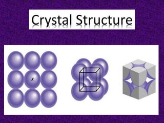
  • 11. 1 atom/unit cell (8 x 1/8 = 1) 2 atoms/unit cell (8 x 1/8 + 1 = 2) 4 atoms/unit cell (8 x 1/8 + 6 x 1/2 = 4)
  • 12.
  • 13. Atom positions, crystal directions and Miller indices The structure of a crystal is defined with respect to a unit cell. As the entire crystal consists of repeating unit cells, this definition is sufficient to represent the entire crystal. Within the unit cell, the atomic arrangement is expressed using coordinates. For example, consider a cubic cell of dimension 3.52 Å. Pretend that this cell contains an atom that has the coordinates (1.5, 2.1, 2.4). That is, the atom is 1.5 Å away from the origin in the x direction (which coincides with the a cell axis), 2.1 Å in the y (which coincides with the b cell axis) and 2.4 Å in the z (which coincides with the c cell axis). There will be an equivalent atom in the next unit cell along the x-direction, which will have the coordinates (1.5 + 3.52, 2.1, 2.4) or (5.02, 2.1, 2.4). This was a rather simple calculation, as the cell has very high symmetry and so the cell axes, a, b and c, coincide with the Cartesian axes, X, Y and Z. Accordingly, atomic coordinates are usually expressed in terms of fractional coordinates, (x, y, z). This coordinate system is coincident with the cell axes (a, b, c) and relates to the position of the atom in terms of the fraction along each axis. Consider the atom in the cubic cell discussion above. The atom was 1.5 Å in the a direction away from the origin. As the a axis is 3.52 Å long, the atom is (1.5/3.52) or 0.43 of the axis away from the origin. Similarly, it is (2.1/3.52) or 0.60 of the b axis and (2.4/3.5) or 0.68 of the c axis. The fractional coordinates of this atom are, therefore, (0.43, 0.60, 0.68). The coordinates of the equivalent atom in the next cell over in the a direction, however, are easily calculated as this atom is simply 1 unit cell away in a. Thus, all one has to do is add 1 to the x coordinate: (1.43, 0.60, 0.68). Such transformations can be performed regardless of the shape of the unit cell. Fractional coordinates, therefore, are used to retain and manipulate crystal information.
  • 14. Miller Indices (hkl) Miller indices are a notation system in crystallography for planes and directions in crystal (Bravais) lattices. The orientation of a surface or a crystal plane may be defined by considering how the plane (or indeed any parallel plane) intersects the main crystallographic axes of the solid. The application of a set of rules leads to the assignment of the Miller Indices , (hkl) ; A set of numbers which quantify the intercepts and thus may be used to uniquely identify the plane or surface. The designation of the individual vectors within any given crystal lattice is indicated by the notation [hkl], where h, k, and l are reciprocals of the point at which the vector exits the unit cell. The origination of all vectors is assumed defined as [000]. For example, the direction along the a-axis according to this scheme would be [100] because this has a component only in the a-direction and no component along either the b or c axial direction.
  • 15. Miller Indices are a symbolic vector representation for the orientation of an atomic plane in a crystal lattice and are defined as the reciprocals of the fractional intercepts which the plane makes with the crystallographic axes. A vector diagonally along the face defined by the a and b axis would be [110], while going from one corner of the unit cell to the opposite corner would be in the [111] direction. Figure 2 shows some examples of the various directions in the unit cell. The crystal direction notation is made up of the lowest combination of integers and represents unit distances rather than actual distances. A [222] direction is identical to a [111], so [111] is used. Fractions are not used. For example, a vector that intercepts the center of the top face of the unit cell has the coordinates x = 1/2, y = 1/2, z = 1. All have to be inversed to convert to the lowest combination of integers (whole numbers); i.e., [221] in Figure 2. Finally, all parallel vectors have the same crystal direction, e.g., the four vertical edges of the cell shown in Figure 2 all have the crystal direction [hkl] = [001].
  • 16.
  • 17. Crystal directions may be grouped in families. To avoid confusion there exists a convention in the choice of brackets surrounding the three numbers to differentiate a crystal direction from a family of direction. For a direction, square brackets [hkl] are used to indicate an individual direction. Angle brackets <hkl> indicate a family of directions. A family of directions includes any directions that are equivalent in length and types of atoms encountered. For example, in a cubic lattice, the [100], [010], and [001] directions all belong to the <100> family of planes because they are equivalent. If the cubic lattice were rotated 90°, the a, b, and c directions would remain indistinguishable, and there would be no way of telling on which crystallographic positions the atoms are situated, so the family of directions is the same. In a hexagonal crystal, however, this is not the case, so the [100] and [010] would both be <100> directions, but the [001] direction would be distinct. Finally, negative directions are identified with a bar over the negative number instead of a minus sign.
  • 19. Planes in a crystal can be specified using a notation called Miller indices. The Miller index is indicated by the notation [hkl] where h, k, and l are reciprocals of the plane with the x, y, and z axes. To obtain the Miller indices of a given plane requires the following steps: Step 1. The plane in question is placed on a unit cell. Step 2. Its intercepts with each of the crystal axes are then found. Step 3. The reciprocal of the intercepts are taken. Step 4. These are multiplied by a scalar to insure that is in the simple ratio of whole numbers. For example, the face of a lattice that does not intersect the y or z axis would be (100), while a plane along the body diagonal would be the (111) plane. An illustration of this along with the (111) and (110) planes is given in Figure 3. Crystal Planes & Miller Indices
  • 21. Description of Crystal Structure 1. The size and shape of the unit cell 2. Positions of the atoms (or ions) within the cell However, this information is sometimes insufficient to allow for an understanding of the true structure in three dimensions. Consideration of several unit cells, the arrangement of the atoms with respect to each other, the number of other atoms they in contact with, and the distances to neighboring atoms, often will provide a better understanding. Close packed structures: hexagonal close packing and cubic close packing In geometry, close-packing of spheres is a dense arrangement of equal spheres in an infinite, regular arrangement (or lattice). The highest average density – that is, the greatest fraction of space occupied by spheres – that can be achieved by a regular lattice arrangement is 0.74048. The packing efficiency (volume of space occupied by the spheres/total volume) is 74.05 % for both cubic and hexagonal close packing schemes.
  • 22. Within the square packed layer the coordination # of each atom is 4, in the close packed layer it is 6. Square Packed Layer Close packed array.
  • 23. FCC and HCP lattices There are two simple regular lattices that achieve this highest average density. They are called face-centered cubic (fcc) (also called cubic close packed) and hexagonal close-packed (hcp), based on their symmetry. Both are based upon sheets of spheres arranged at the vertices of a triangular tiling; they differ in how the sheets are stacked upon one another. A single layer of spheres is closest-packed with HEXAGONAL coordination of each sphere
  • 24. A second layer of spheres is placed in the indentations left by the first layer space is trapped between the layers that is not filled by the spheres TWO different types of HOLES (so-called INTERSTITIAL sites) are left OCTAHEDRAL (O) holes with 6 nearest sphere neighbours TETRAHEDRAL (T±) holes with 4 nearest sphere neighbours
  • 25. When a third layer of spheres is placed in the indentations of the second layer there are TWO choices The third layer lies in indentations directly in line (eclipsed) with the 1st layer. Layer ordering may be described as ABA The third layer lies in the alternative indentations leaving it staggered with respect to both previous layers. Layer ordering may be described as ABC
  • 26. Figure : Schematic representation of the three close packed layers in a cubic close packed arrangement: A (dark grey), B (medium grey), and C (light grey).
  • 27. If two close packed layers A and B are placed in contact with each other so as to maximize the density, then the spheres of layer B will rest in the hollow (vacancy) between three of the spheres in layer A. This is demonstrated in Figure. Atoms in the second layer, B (shaded light gray), may occupy one of two possible positions (Figure a or b) but not both together or a mixture of each. If a third layer is placed on top of layer B such that it exactly covers layer A, subsequent placement of layers will result in the following sequence ...ABABAB.... This is known as hexagonal close packing or hcp.
  • 28. Octahedral and tetrahedral vacancies As was mentioned above, the packing fraction in both fcc and hcp cells is 74.05%, leaving 25.95% of the volume unfilled. The unfilled lattice sites (interstices) between the atoms in a cell are called interstitial sites or vacancies. The shape and relative size of these sites is important in controlling the position of additional atoms. In both fcc and hcp cells most of the space within these atoms lies within two different sites known as octahedral sites and tetrahedral sites. The difference between the two lies in their “coordination number”, or the number of atoms surrounding each site. Tetrahedral sites (vacancies) are surrounded by four atoms arranged at the corners of a tetrahedron. Similarly, octahedral sites are surrounded by six atoms which make-up the apices of an octahedron. For a given close packed lattice an octahedral vacancy will be larger than a tetrahedral vacancy. Within a face centered cubic lattice, the eight tetrahedral sites are positioned within the cell, at the general fractional coordinate of (n/4,n/4,n/4) where n = 1 or 3, e.g., (1/4,1/4,1/4), (1/4,1/4,3/4), etc. The octahedral sites are located at the center of the unit cell (1/2,1/2,1/2), as well as at each of the edges of the cell, e.g., (1/2,0,0). In the hexagonal close packed system, the tetrahedral sites are at (0,0,3/8) and (1/3,2/3,7/8), and the octahedral sites are at (1/3,1/3,1/4) and all symmetry equivalent positions.
  • 29. Diamond Cubic Structure The diamond cubic structure consists of two interpenetrating face-centered cubic lattices, with one offset 1/4 of a cube along the cube diagonal. It may also be described as face centered cubic lattice in which half of the tetrahedral sites are filled while all the octahedral sites remain vacant. The diamond cubic unit cell is shown in Figure . Each of the atoms (e.g., C) is four coordinate, and the shortest interatomic distance (C-C) may be determined from the unit cell parameter (a). Figure : Unit cell structure of a diamond cubic lattice showing the two interpenetrating face-centered cubic lattices.
  • 30. Zinc blende As with the diamond lattice, zinc blende consists of the two interpenetrating fcc lattices. However, in zinc blende one lattice consists of one of the types of atoms (Zn in ZnS), and the other lattice is of the second type of atom (S in ZnS). It may also be described as face centered cubic lattice of S atoms in which half of the tetrahedral sites are filled with Zn atoms. All the atoms in a zinc blende structure are 4- coordinate. The zinc blende unit cell is shown in Figure. A number of inter-atomic distances may be calculated for any material with a zinc blende unit cell using the lattice parameter (a). Figure : Unit cell structure of a zinc blende (ZnS) lattice. Zinc atoms are shown in green (small), sulfur atoms shown in red (large), and the dashed lines show the unit cell.
  • 31. Rock salt As its name implies the archetypal rock salt structure is NaCl (table salt). In common with the zinc blende structure, rock salt consists of two interpenetrating face-centered cubic lattices. However, the second lattice is offset 1/2aalong the unit cell axis. It may also be described as face centered cubic lattice in which all of the octahedral sites are filled, while all the tetrahedral sites remain vacant, and thus each of the atoms in the rock salt structure are 6-coordinate. The rock salt unit cell is shown in Figure. A number of inter- atomic distances may be calculated for any material with a rock salt structure using the lattice parameter (a). Figure : Unit cell structure of a rock salt lattice. Sodium ions are shown in purple (small spheres) and chloride ions are shown in red (large spheres).
  • 32. Cesium Chloride The cesium chloride structure is found in materials with large cations and relatively small anions. It has a simple (primitive) cubic cell (Figure ) with a chloride ion at the corners of the cube and the cesium ion at the body center. The coordination numbers of both Cs+ and Cl-, with the inner atomic distances determined from the cell lattice constant (a).