Operational mechanisms of feed mill
•
37 likes•9,759 views

Operational mechanisms of feed mill

Recommended
More Related Content
What's hot
What's hot (20)
Viewers also liked
Viewers also liked (20)
Similar to Operational mechanisms of feed mill
Similar to Operational mechanisms of feed mill (20)
More from Ashiq Toor
More from Ashiq Toor (12)
Recently uploaded
Recently uploaded (20)
Operational mechanisms of feed mill
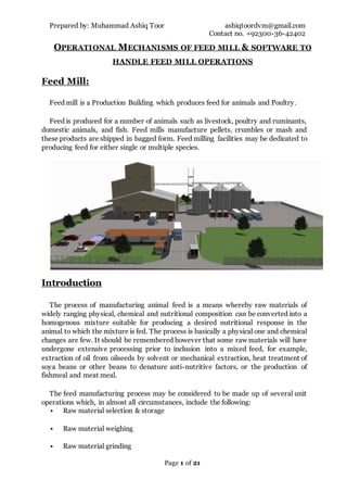
- 1. Prepared by: Muhammad Ashiq Toor ashiqtoordvm@gmail.com Contact no. +92300-36-42402 Page 1 of 21 OPERATIONAL MECHANISMS OF FEED MILL & SOFTWARE TO HANDLE FEED MILL OPERATIONS Feed Mill: Feed mill is a Production Building which produces feed for animals and Poultry. Feed is produced for a number of animals such as livestock, poultry and ruminants, domestic animals, and fish. Feed mills manufacture pellets, crumbles or mash and these products are shipped in bagged form. Feed milling facilities may be dedicated to producing feed for either single or multiple species. Introduction The process of manufacturing animal feed is a means whereby raw materials of widely ranging physical, chemical and nutritional composition can be converted into a homogenous mixture suitable for producing a desired nutritional response in the animal to which the mixture is fed. The process is basically a physical one and chemical changes are few. It should be remembered however that some raw materials will have undergone extensive processing prior to inclusion into a mixed feed, for example, extraction of oil from oilseeds by solvent or mechanical extraction, heat treatment of soya beans or other beans to denature anti-nutritive factors, or the production of fishmeal and meat meal. The feed manufacturing process may be considered to be made up of several unit operations which, in almost all circumstances, include the following: Raw material selection & storage Raw material weighing Raw material grinding
- 2. Prepared by: Muhammad Ashiq Toor ashiqtoordvm@gmail.com Contact no. +92300-36-42402 Page 2 of 21 Mixing of dry ingredients and addition of liquids Pelleting of mixed feed (optional) Blended feed bagging, storage and dispatch RAW MATERIAL SELECTION & STORAGE The raw materials coming into a feed process area will have been requested by the nutritionist as being necessary to meet the nutrient requirements of the diet to be manufactured. Laboratory testing of raw ingredients: Hygrometer1 give result within 30 sec 14% normal, if 15% so 1% reduction in weight is considered. More than 15% = rejected 1 A hygrometer is an instrument used for measuringthe moisture content in the specific grains.
- 3. Prepared by: Muhammad Ashiq Toor ashiqtoordvm@gmail.com Contact no. +92300-36-42402 Page 3 of 21 In order toensure a continuous supply of raw materials at the mill, when some may only be seasonally available on the market, and to take advantage of price fluctuations, some form of storage will be necessary. Raw materials should arrive in good condition and in sacks which have not been used for the storage of fertilizer, pesticides or chemicals. Storage areas must be waterproof and well-ventilated, and provide protection against infestation by insects and vermin which can quickly cause substantial losses in weight. If materials are to be stored in bags they should be kept in a building having a concrete floor. Theroof and walls need only to be lightly constructed provided that they are pest and waterproof. The bags should be stacked a few inches above floor level. Ingredients can be transported via: • Bucket elevators • Belt conveyors • Paddle conveyors • Drag chain conveyors.
- 4. Prepared by: Muhammad Ashiq Toor ashiqtoordvm@gmail.com Contact no. +92300-36-42402 Page 4 of 21 The most common type of conveyor in feed mills is the screw conveyor, because it offers the potential for easy transporting of materials. The two major materials of construction that are used for feed mills are: • Concrete • Steel Concrete feed mills are used for large scale facilities. Steel feed mills are especially common for smaller-scale facilities. A specific design consideration for a given feed mill is the amount of space allocated to storage of bulk ingredients. Each silo has 7 monitoring sensors one at centre and other in circle around the centre and sheets. Capacity formula. A= volume of cylinder B = volume of cone r = radius H = height If 22 kg maize in one cubic feet so, Volume of silo × 22 = total capacity of silo. 1 silo= 2500 tons of maize, wheat, rice tips. Raw material weighing/Batching System: The accurate weighing of raw materials according to the formulation for a given ration is perhaps the most important unit operation involved in feed manufacture, since no amount of mechanical processing can make up for any deficiencies in nutrients 𝑨 = 𝝅𝒓 𝟐 × 𝑯 B = 1.047 × 𝒓 𝟐 × H A + B = Volume of silo
- 5. Prepared by: Muhammad Ashiq Toor ashiqtoordvm@gmail.com Contact no. +92300-36-42402 Page 5 of 21 which have been omitted from the mixture. The point at which weighing occurs in the feed milling process will depend upon the design of the mill. Raw materials may be selected from store, weighed and then subjected to grinding and mixing, or materials may be pre-ground, then weighed and mixed. Large bin-type weighers are often used for raw materials which have been pre- ground or are free flowing and discharge readily from storage bins or silos. Bin-type weighers may be mobile or stationary. Inline weighers which measure the quantity of material flowing over a small electronic sensor and volumetric dischargers are also available. Bins capacities Each bin consist of two parts, Concrete part Hopper ( steel made ) Volume of bin calculate by calculating and add the volume of concrete part and hopper So, Volume of concrete bin = L × W × H = 10.5×10.5×25 = 2756 cubic feet Volume of Rectangular shape hopper L1 = 10.5 L2 = 3.33 B1 = 10.5 B2 = 1.66 567 cubic feet volume of hopper according to formula Total volume is 3324 cf If 15 kg material in 1 cf then 50 tons capacity Main scale is 3 ton 16 micro bins are installed above the main scale 1bin capacity is 500 bag. In order to produce particular feed mixtures, appropriate quantities of specific ingredients must be transferred out of storage and transported to the mixer. This is the function of the batching system.
- 6. Prepared by: Muhammad Ashiq Toor ashiqtoordvm@gmail.com Contact no. +92300-36-42402 Page 6 of 21 For all major and minor ingredients, the equipment used to for this includes screw conveyors which provide excellent proportioning control, and scale hoppers above the mixer. Bulk bag and hand dump stations are also frequently used to add ingredients to the feed mixture. The weighing of raw materials requires great care and inaccuracies must be kept to a minimum. It should be noted that errors in the weighing of small quantities of raw materials often have far greater influence on the growth performance of animals than errors in the weighing of large quantities of material, Raw material grinding Prior to utilization in feed formulations, whole grain must be ground to reduce particle size. Grinding before mixing more better than after batching. Reasons: Large fragments are reduced in size. Some moisture is removed due to aeration. Additives such as antioxidants may be blended. All of these improve the ease of handling ingredients and their storability. The grinding of ingredients generally improves feed digestibility, mixing properties, palatability, and increases the bulk density of some ingredients. In the sequence of unit operations involved in feed milling, raw material grinding may occur before or after weighing. It is a process with high power requirements which
- 7. Prepared by: Muhammad Ashiq Toor ashiqtoordvm@gmail.com Contact no. +92300-36-42402 Page 7 of 21 is often noisy and dusty. The design of machine most commonly found in the feed. Inside the grinding chamber, hammers, which may be fixed rigidly to the central shaft, or more often swinging on steel pins, rotate at high speed. The impact of the raw material on the hammers and the continual high-velocity impact of particle on particle results in material breakdown until it is small enough in size to pass through a perforated screen. Grinding systems are generally located directly under whole grain storage bins. Roller mills are gaining popularity because of their ability to produce coarse, uniform particle size, with reduced noise levels and power consumption. If ground material is conveyed pneumatically, the air and material are separated in a cyclone2 . This simple device, which is similar to an inverted cone, causes air to swirl around its walls depositing the ground material at the base of the cone while the air exits at the top of the cyclone through a filter. Cyclones are normally only 95% efficient at separating ground particles and air, and a cloth or other type of filter is necessary as a dust barrier. The moisture content of raw materials to be ground in a hammer mill should not normally exceed13-14%.High-moisture feeds are plastic or malleable in character with few planes of impact weakness and may clog a conventional hammer mill designed for handling dry ingredients. Mixing of dry ingredientsand addition of liquids It is the job of the mixer to produce a homogenous blend of all the raw materials desired in a formulation, such that at each feeding period each animal receives a balanced mixture of nutrients 2 Cyclone is dustcollector.
- 8. Prepared by: Muhammad Ashiq Toor ashiqtoordvm@gmail.com Contact no. +92300-36-42402 Page 8 of 21 Mixing often improves feed palatability if one or more of the raw materials is unpalatable to livestock Concrete mixers Small concrete mixers with electric or petrol engine drives are mobile low cost machines suitable for the manufacture of mixtures of dry ingredients or mixtures of wet feeds, For larger-scale feed mixing however it is advisable and probably cheaper to use one of the conventional feed mixers described below. Conventional feed mixers Two designs of mixers are most commonly found in the feed industry: the vertical (or fountain) mixer and the horizontal (or U-trough) mixer. Vertical mixers . Raw materials may enter the mixer either at the top, from a cyclone or auger feed from the grinder, or at the base of the screw at a sack tipping point. After mixing for a pre-determined time, normally 10-15 minutes (although this time may be shorter in some mixes), the mixture is discharged into a bag or conveyed by auger or bucket elevator to a storage bin or pelleter. Since many raw materials are dusty it is often desirable to include materials such as molasses, oils and fats in the formulations to reduce dustiness as well as to provide a source of nutrients. Vertical mixers, because of their slow-running action, are generally less effective in distributing liquids throughout the mixture, and liquids tend to form beadlets or balls coated with fine particle material, rather than produce a surface coating on the solid material Horizontal mixers As the name suggests, horizontal mixers operate with a horizontally turning mixing shaft, the mixer is suitable for blending up to 8% liquids into a dry mix and therefore offers greater versatility if a wide range of rations are to be offered from one feed mill unit. It is preferable that fats and molasses be warmed before addition to the raw materials in the mixer and they should be added as the last ingredients.
- 9. Prepared by: Muhammad Ashiq Toor ashiqtoordvm@gmail.com Contact no. +92300-36-42402 Page 9 of 21 Conveyor mixers Conveyor mixers are also available, particularly for farm use, and consist of a trapezoid metal box in which mixing is effected by slats extending almost the full width of the machine and which are carried on a pair of endless chains. Like the vertical mixer this machine is limited in its ability to blend liquids thoroughly into the mixture. Pelleting of mixed feed Two pellet mills in SFM, 1 pellet mill produce 300bag/hr. (15 ton), 600 bag (poultry feed)/hr. can be produce. The use of pelleted feed is often popular with farmers because it is convenient to handle and reduces dustiness. . Pellets also reduce feed losses during feeding, and may help to maintain, or increase, feed intake under certain conditions. The heat generated during pelleting can inactivate some pathogenic bacteria which may be present in raw materials. However, pelleting increases the cost of feeds because the capital cost of pelleters is relatively high compared to grinders or mixers, the energy requirement is high, and additional care and skill is necessary for their maintenance and operation. Pelleting involves the compression of a mixed feed through holes in a hardened steel ring or plate (a die) by means of hardened steel rollers. The die forms the feed into pencil-like extrusions which are cut by knives into pellets of desired length on leaving the die. Pelleters may also be divided into two further groups according to the pre-treatment of mixed feed prior to compression or extrusion in the die head. Pelleters may be considered as cold pelleters or conditioner pelleters. = = 450 × 391 × 0.9 × 1.732 / 22.5 × 1000 = 12.18kW/tons = 0.609kW/bag Pellet Machine Efficiency A × V × 1.732 × Power Factor Tons / hr × 1000
- 10. Prepared by: Muhammad Ashiq Toor ashiqtoordvm@gmail.com Contact no. +92300-36-42402 Page 10 of 21 Cold pelleters In cold pelleting, mixed feed is fed directly from a bin or auger into the die head at ambient (normal atmospheric) temperatures. Some water may be added, preferably in the mixer if the meal is too dry to bring it to approximately 15-16% moisture, but there is no heat treatment of the mixed meal before it enters the die. Conditioner pelleters The term 'cold pelleting' is something of a misnomer since a considerable amount of heat is generated during the pelleting operation, but it serves todistinguish the process from conditioner pelleting which is the usual process in industrial pelleters. During conditioner pelleting, the mixed meal is directly pre-heated with dry steam. The steam preheats or conditions the meal to the preferred temperature and moisture content for pelleting according to the formulation of the mixture, for example, 65-121°C avg 80°C and 15-25% moisture Generally, the quality of pellets (that is, resistance to break-down after pelleting and during handling) of a given mixture from a conditioner pelleter is marginally better than that from a cold pelleter, but the conditioner pelleter requires a boiler and associated water treatment plant to treat the feed water for the boiler. Factors that Affect Steam Conditioning Mash particle size, Surface area increases geometrically as particle size decreases Retention time 30 to 90 seconds for optimum pellet quality 5 to 20 seconds is more typical in the industry Pick (Paddle) Angle Retention time decreases as forward angle increases. Shaft speed Water Addition Optimum conditioning at16-17.5%moisture, with 4-5%moisture added by the conditioner
- 11. Prepared by: Muhammad Ashiq Toor ashiqtoordvm@gmail.com Contact no. +92300-36-42402 Page 11 of 21 Pellet quality Pellets should have a desired degree of hardness, and should also show high resistance to abrasion during handling and transport. Pellet binders Some mixtures of raw materials do not bind well together when pelleted and require the addition of special binding agents. Molasses is often added at 2-5% to aid binding, but other binders include bentonite clays and lignosulphonates, and are added at the suppliers' recommended dosage levels, usually about 1-2%.
- 12. Prepared by: Muhammad Ashiq Toor ashiqtoordvm@gmail.com Contact no. +92300-36-42402 Page 12 of 21 Cooling & Stabilizing: The Pellet Cooler is used for cooling hot feed pellets from 80o C to ambient temperature. Cooling columns are on either side with central duct for conveying hot air. Wire mesh separates pellets from air. Set of flaps regulate flow of cold air inside the cooler. Thepellets while falling operate inside portion of the flaps and cold air is passed through stock of pellets. Basically three types of coolers used in the feed industry: Vertical Horizontal Counter flow Pellets are then cooled from 80°C to ambient. Crumbling Pellet Crumblier is an essential equipment for the preparation of crumbled pellet feed. The pellets can then be diverted into the crumblier, if crumbles or granules are desired, or they can by-pass it. This is used for breaking the pellets into crumbs required for chicks which are 2-3 weeks old. Pellets are broken into pieces of the required size between the two rolls of the crumblier situated below the cooler/drier exit. The gap between the rolls can be adjusted to regulate the size of crumbs. The roller gap is adjusted with a hand wheel mechanism.
- 13. Prepared by: Muhammad Ashiq Toor ashiqtoordvm@gmail.com Contact no. +92300-36-42402 Page 13 of 21 Sieve Grading: Grading rotary sieve is made to grade and screen the pellets getting gone through crushing in the large or medium-sized animal feed. It is also used to clean the initial materials to process pellets. It is applicable for screening and classifying of mash or pellet feed. It is also can be used for cleaning of raw materials. Large pellets and very small particles with ground material are recycled through the pelleting machine. Bagging / Packing: Load Cell Type Bagging Machine The Load Cell Type Bagging Machine or Bagging-Off-Weigher is an electronically controlled bagging machine. It is a heavy-duty machine for the repeated and accurate weighment in bags of products like pelleted or mashed feed, grains, sugar and cereals. It
- 14. Prepared by: Muhammad Ashiq Toor ashiqtoordvm@gmail.com Contact no. +92300-36-42402 Page 14 of 21 consists of a bin hopper, feeder with slow-speed and high-speed drives, a weighment chute supported on load cells and a pneumatically operated bag clamp. The accuracy of the machine is 0.2 %. When bag put at mouth of cell, clump took message to sliding gate open for specific weight of feed dragging down in bag, as weight attained according to our input to load cell. Load cell message to pneumatically controlled cylinders to close the gates. As gate close clumps release and bag moves to sieving machine by belt conveyer. Here packing complete and feed bag either store in store house or directly load to vehicle. Automatic filling of feed bag This Portable bag closing machine is widely used in sewing feed bags, rice bags, fertilizers bags and seed bags. Load out: • Feed bag packing 50 kg poultry feed , Wanda 37 kg / bag
- 15. Prepared by: Muhammad Ashiq Toor ashiqtoordvm@gmail.com Contact no. +92300-36-42402 Page 15 of 21 Dryer Drying is the process that reduces grain moisture content to a safe level for storage, Proper Drying will maintain grain quality and minimize losses. Purposes of Drying The purpose of drying is to reduce the moisture content of rough rice to a level safe for storage. Drying of grain involves exposing grain to ambient air with low relative humidity or to heated air. This will evaporate the moisture from the grain and then the drying air will remove the moisture from the grain. Types of dryer Continuous flow dryer Conventional Continuous Flow Dryer Cross flow dryers Counter flow dryers Flash Dryer The fluidized bed dryer consists of a drying chamber with an air speed of around 2.3 m/s, a bed thickness of 10 cm in which the grain is exposed to the drying air for 10-15 minutes. Capacities of commercial units range from 1-10 t/h. A diesel burner or a rice hull furnace is used as heat source and a system for recycling 50- 70% of the drying air is provided to improve energy efficiency.
- 16. Prepared by: Muhammad Ashiq Toor ashiqtoordvm@gmail.com Contact no. +92300-36-42402 Page 16 of 21 Cross flow dryers Cross flow dryers are of simple design. In the drying zone the grain moves downwards between two perforated metal sheets while the air moves horizontally through the grains Parts of dryer Perforated metal sheets 44 rings Twoblur fans 75 hp motor of each FD (forced) fan 50 hp motor Heat exchanger Rotary 3 hp motor Steam header Dryer panel Conveyer and elevators At top of the dryer material enter which we want to decrease moisture. It has 12feet external diameter, and internally 10 feet. it is made up 44 rings of perforated sheet internal and external cylinder, each ring contains 7 sheet, total height is of 70 feet. As material enter spread in between the both sheets. Capacity almost 30 tons / hr. FD fan installed some height from the bottom, FD fan forced the air to heat exchanger, in heat exchanger a lot of steam pipes net. As air cross these pipes area warm up to 100-120 degree Celsius. In heat exchanger steam pressure 120 psi. When warm air enter in the shell of dryer two blur installed at bottom of shell forced the hot air towards top of dryer. This hot air cross from material to dry the material, maximum temperature at top of dryer, as moves downward temperature gradually deceases, in last five rings of dryer use to decrease the temperature of material, and after completing the drying process when required moisture attained material comes out through rotary. Rotary speed can be adjusted according to moisture level of material, if more moisture than rotary speed slower down for more exposure to hot air to material. Rotary speed can be vary from 10-60 Rev. per Min. at 26 rev. rotary speed 10tons paddy dry per hour from moisture 20 to 12 %.
- 17. Prepared by: Muhammad Ashiq Toor ashiqtoordvm@gmail.com Contact no. +92300-36-42402 Page 17 of 21 Boiler Boiler broadly classified into twocategories, Water tube Fire tube Fire Tube Water Tube Fire inside the tubes Water inside the tube Less space required More Less Expensive More Easily moveable Not to move Easy to clean Difficult to clean as no. of tubes more and ‘D’ shape More fuel required Less fuel Single pass to 4 pass fire in tubes to increase the fuel utilization Single pass to 4 pass fire by bricks dimensions In Hi-Tech feed mill Unit 3 Sahiwal In Hi-Tech oil mill. Boilers are classified as on the base of fuel also such as Gas, Diesel, wood, coal etc. Fire tube boiler of 5 tons per hour capacity. Capacity of boiler depends upon on the heating surface of the boiler 1350 feet square heating surface. Wood use as fuel in In Hi-Tech feed mill Unit 3 Sahiwal, wood produce 4tons steam per 1 ton of wood. Maximum pressure of steam at boiler is 150psi, it is controlled by the safety valve. Water pH 8 and TDS 100 of water which is used to produce steam Parts of boiler Three main thing to run the boiler 1. FD (Forced) Fan; its function is forced the air into furnace (combustion chamber) to stimulate the fire, its running motor is 5 hp. 2. ID (induced) Fan; it induced the air from main shell/ boiler to chimney, having motor 40hp. 3. Water Feed Pump also call multistage centrifugal pump; it consist of stages/ impellers, function of impeller is to increase pressure. Its pressure 1.5 times more than boiler inside pressure. Other parts Drying pipe; its function is to allow only steam to move out and filter the water drops. Rose pipe; it acts like a shower, prevent the water directly hitting on fire tubes
- 18. Prepared by: Muhammad Ashiq Toor ashiqtoordvm@gmail.com Contact no. +92300-36-42402 Page 18 of 21 Safety valve; It control the pressure up to 150psi, above its range that will open and save the over pressure problems in the boiler. Main hole; entry point for repairing purposes. Air valves; toremove vaccum from the boiler when again start after some time break. Cyclone; to separate ash and dust, allow smoke to release out. Below down valve; for water discharge from the boiler. Water level gauge glass; to check water level. Stop valve; tostop the steam Steam Flow From boiler to conditioner throughout steam line 4inch and insulated. Distributer (Header) it get steam and distribute the steam to multiple lines, near to boiler, dryer and next pellet sides. Strainer: it is sieve type valve use tofiltrate the particles from the steam to protect the seats of valve. Steam Trap: it is use to separate the water from the steam Pressure reducing valves: use to control the pressure in a constant way, use before the conditioner to avoid the over conditioning problems. At pellet side trapper valves separate the water this water comes back into boiler for recycling by two inch pipe line. RO (Reverse Osmoses) Plant Sand filter; it can bear 20 psi pressure, it remove heavy sand particles Bag filter; it filter the particles those pass out from the sand filter Cartridge filter; seven in no. in series, these work to filter more fine particles at high pressure Pump; it takes water from cartridge filter to membranes Membranes; two in no, these control the TDS, separate the TDS water and pure water Chemicals; Flocon 260, AQASIS 744 to control the TDS PLC (programmable Logic Control) This consists of a list of logic functions and instructions, which are successively processed through a program. Control System This a customizable software and hardware package. With a custom hardware and software solution you have the ability to monitor and completely control a facility from a PC. The operation of the PLC controller can be monitored and changed via the keyboard/mouse and the recipes/alarming log etc. The PLC graphically displays the information on a screen (touch screen or standard) and allows the user to manipulate the data on the PLC (start/stop motors, view outgoing batches etc.) Some powerful features of the control system are, This greatly reduces operational cost while increasing facility efficiency.
- 19. Prepared by: Muhammad Ashiq Toor ashiqtoordvm@gmail.com Contact no. +92300-36-42402 Page 19 of 21 Allows for quick and easy administration decisions It is programmable to fit the customer’s needs It is easily expandable to fit the customers growing and changing needs This will control major, minor, and micro ingredients through one scale or several scales along with control of liquid ingredients. With the automatic batch mixing process the control package can control automatic destination of the mixed product. Control Systems development time reduced by up to 80% It reduced overall costs of development, boost of productivity and dramatically increased reliability. Todesign input data we need following specifications All inputs that are given to software program are in the form of a statement Record of Inputs/Outputs that connected to PLCs Records specifying lists of plant facilities of different variety controlled by the system like motors, valves and their control parameters. Records of Control Sequences, Control state machines, interlocking etc. List of PLCs used, their types and configuration and memory map. Currently, for auto generation purposes, design input data is stored in Excel spreadsheets, but it can be provided in the form of Access data bases or SQL databases. The PLC program being developed, could be for any kind of industrial automation application one can think of (e.g. process control, machine control, automated production lines, oil refineries, water supply/treatment etc.) Structure of a PLC Program They consist of individual, separately defined programs sections which are executed in sequence. These programs sections are called blocks (input/output block, etc.) The blocks are functionally independent. Assigning a particular (technical) function to a specific block, which has clearly defined and simple interfaces with other blocks Blocks contain the program logic graphically represented. Programming Languages PLC programs can be constructed using various methods of representation. Some of the common ones are, described below. The Relay Ladder Logic (RLL) Diagram: It is a visual and logical method of displaying the control logic which, based on the inputs determine the outputs of the program. The ladder is made up of a series of “rungs” of logical expressions expressed graphically as series and parallel circuits of relay logic elements such as contacts, timers etc. Each rung consist of a set of inputs on the left end of the rung and a single output at the right end of each.
- 20. Prepared by: Muhammad Ashiq Toor ashiqtoordvm@gmail.com Contact no. +92300-36-42402 Page 20 of 21 Inputs/Outputs: The input operands refer to external physical signals of the controlled system, whose values are acquired from the input signal modules Internal Variable Operands or Flags Their function is to save intermediate computational values of the program. Timer: These are special operands of a PLC, which represent a time delay relay in a relay logic system. It is possible to achieve time delays in the range of few milliseconds to few hours. Counter: Thecounting functions (C) operate as hardware. Thecounting range is from 0 to 999. PLC program Cycle: When Initialise the PLC then scanning starts then it read all inputs individually then processed the PLC program memory, when match thePLC memory with the Software stored memory then it update all out puts. The time required by the microprocessor to complete one cycle is known as the scan time. After all rungs have been tested, the PLC then starts over again with the first rung. Of course the scan time for a particular processor is a function of the processor speed, the number of rungs, and the complexity of each rung. Motor Interlocking Pelleting interlocking system Rotary (Cyclone) Cyclone Screener Elevator Convayer
- 21. Prepared by: Muhammad Ashiq Toor ashiqtoordvm@gmail.com Contact no. +92300-36-42402 Page 21 of 21 Mixer to Pellet bins Interlocking Crumblers Cooler Rotary (below pellet) Pellets Conditioner 1 then 2 then feeder Convayer(above pellet bins) Drum cleaner elevator convayers