SlideShare une entreprise Scribd logo
1  sur  23
3. Data Link Layer Compiled By: Er. Jeewan Rai
1
- Second layer of OSI Layered Model.
- Ensures that an initial connection has been set up, divides output data into data frames,
and handles the acknowledgements from a receiver that the data arrived successfully.
- responsible for converting data stream to signals bit by bit and to send that over the
underlying hardware. At the receiving end, Data link layer picks up data from hardware
which are in the form of electrical signals, assembles them in a recognizable frame
format, and hands over to upper layer.
- Data link layer has two sub-layers:
 Logical Link Control: It deals with protocols, flow-control, and error control
 Media Access Control: It deals with actual control of media
3.1 Functions of Data Link Layer
Data link layer does many tasks on behalf of upper layer. These are:
 Framing: Data-link layer takes packets from Network Layer and encapsulates them into Frames. Then, it sends each frame bit-by-bit
on the hardware. At receiver’ end, data link layer picks up signals from hardware and assembles them into frames.
 Addressing : Data-link layer provides layer-2 hardware addressing mechanism. Hardware address is assumed to be unique on the
link. It is encoded into hardware at the time of manufacturing.
 Synchronization : When data frames are sent on the link, both machines must be synchronized in order to transfer to take place.
 Error Control: Sometimes signals may have encountered problem in transition and the bits are flipped. These errors are detected and
attempted to recover actual data bits. It also provides error reporting mechanism to the sender.
 Flow Control : Stations on same link may have different speed or capacity. Data-link layer ensures flow control that enables both
machine to exchange data on same speed.
 Multi-Access : When host on the shared link tries to transfer the data, it has a high probability of collision. Data-link layer provides
mechanism such as CSMA/CD to equip capability of accessing a shared media among multiple Systems.
3.2 Framing
In the OSI model of computer networking, a frame is
the protocol data unit at the data link layer. Frames are the
result of the final layer of encapsulation before the data is
transmitted over the physical layer. A frame is "the unit of
transmission in a link layer protocol, and consists of a link
layer header followed by a packet." Each frame is separated
from the next by an interframe gap. A frame is a series of bits
generally composed of framing bits, the packet payload, and
a frame check sequence. Examples are Ethernet
frames, Point-to-Point Protocol (PPP) frames, Fiber Channel
frames, and V.42 modem frames.
- Encapsulate datagram into frame, adding header,
trailer
- Chanel access if shared medium
- “MAC” addresses used in frame headers to identify source, destination and its different from IP address!
Fixed-SizeFraming : Frames can be of fixed or variable size. In fixed-size framing, there is no need for defining the boundaries of the frames;
the size itself can be used as a delimiter. An example of this type of framing is the ATM wide-area network, which uses frames of fixed size
called cells.
Variable-size framing : is prevalent in local- area networks. In variable-size framing, we need a way to define the end of the frame and the
beginning of the next. Historically, two approaches were used for this purpose: a character-oriented approach and a bit-oriented approach.
Bit stuffing:
 Allows frame to contain arbitrary number of bits and arbitrary character size. The frames are separated by separating flag.
 Each frame begins and ends with a special bit pattern, 01111110 called a flag byte. When five consecutive l's are encountered
in the data, it automatically stuffs a '0' bit into outgoing bit stream.
 In this method, frames contain an arbitrary number of bits and allow character codes with an arbitrary number of bits per
character. In his case, each frame starts and ends with a special bit pattern, 01111110.
 In the data a 0 bit is automatically stuffed into the outgoing bit stream whenever the sender's data link layer finds five
consecutive 1s.
- Data - The packet from the Network layer
- Header - Contains control information, such as addressing, and is
located at the beginning of the PDU
- Trailer - Contains control information added to the end of the PDU
3. Data Link Layer Compiled By: Er. Jeewan Rai
2
 This bit stuffing is similar to byte stuffing, in which an escape byte is stuffed into the outgoing character stream before a flag
byte in the data.
 When the receiver sees five consecutive incoming i bits, followed by a o bit, it automatically destuffs (i.e., deletes) the 0 bit. Bit
Stuffing is completely transparent to network layer as byte stuffing. The figure1 below gives an example of bit stuffing.
 This method of framing finds its application in networks in which the change of data into code on the physical medium contains
some repeated or duplicate data. For example, some LANs encodes bit of data by using 2 physical bits.
Byte stuffing:
 In this method, start and end of frame are recognized with the help of flag bytes. Each frames starts with and ends with a flag
byte. Two consecutive flag bytes indicate the end of one frame and start of the next one. The flag bytes used in the figure 2
used is named as “ESC” flag byte.
 A frame delimited by flag bytes. This framing method is only applicable in 8-bit character codes which are a major disadvantage
of this method as not all character codes use 8-bit characters e.g. Unicode.
 Four example of byte sequences before and after stuffing:
3.3 Error Detection and Corrections
There are many reasons such as noise, cross-talk etc., which may help data to get corrupted during transmission. The upper layers work
on some generalized view of network architecture and are not aware of actual hardware data processing. Hence, the upper layers expect
error-free transmission between the systems. Most of the applications would not function expectedly if they receive wrong data.
Applications such as voice and video may not be that affected and with some errors they may still function well.
Data-link layer uses some error control mechanism to ensure that frames (data bit streams) are transmitted with certain level of accuracy.
But to understand how errors is controlled, it is essential to know what types of errors may occur.
Types of Errors
There may be three types of errors:
 Single bit error : In a frame, there is only one bit, anywhere though, which is corrupt.
3. Data Link Layer Compiled By: Er. Jeewan Rai
3
 Multiple bits error : Frame is received with more than one bits in corrupted state.
 Burst error : Frame contains more than1 consecutive bits corrupted.
Error control mechanism may involve two possible ways:
 Error detection :It allows a receiver to check whether received data has been corrupted during transmission. It can, for example,
request a retransmission.
 Error correction : This type of error control allows a receiver to
reconstruct the original information when it has been corrupted
during transmission.
Error Detection
Errors in the received frames are detected by means of Parity Check and
Cyclic Redundancy Check (CRC). In both cases, few extra bits are sent along
with actual data to confirm that bits received at other end are same as they
were sent. If the counter-check at receiver’ end fails, the bits are considered corrupted.
Parity Check
One extra bit is sent along with the original bits to make number of 1s either even in case of even parity, or odd in case of odd parity.
The sender while creating a frame counts the number of 1s in it. For example, if even parity is used and number of 1s is even then one bit
with value 0 is added. This way number of 1s remains even. If the number of 1s is odd, to make it even a bit with value 1 is added.
The receiver simply counts the number of 1s in a frame. If the count of 1s is even and even parity is used, the frame is considered to be
not-corrupted and is accepted. If the count of 1s is odd and odd parity is used, the frame is still not corrupted.
If a single bit flips in transit, the receiver can detect it by
counting the number of 1s. But when more than one bits
are error, then it is very hard for the receiver to detect the
error.
Example for Parity bit :-
- Suppose the sender wants to send the word
“world” in ASCII the five characters are coded as
1110111 1101111 1110010 1101100 1100100 =>
11101110 11011110 11100100 11011000
11001001
- Now suppose the word “world” in example 1 is
received by receiver without corrupted in
transmission.
The receiver counts the one(1’s) in each character
and comes up with even numbers (6,6,4,4,4). The
data are accepted
- Now suppose the word “world” in example 1 is
corrupted during transmission, The receiver
counts the one(1’s) in each character and comes
up with even and odd numbers (7,6,5,4,4).
The receiver knows that the data are corrupted,
discards them and asks for re-transmission.
Parity Check
3. Data Link Layer Compiled By: Er. Jeewan Rai
4
Cyclic Redundancy Check (CRC)
CRC is a different approach to detect if the received frame
contains valid data. This technique involves binary division of
the data bits being sent. The divisor is generated using
polynomials. The sender performs a division operation on the
bits being sent and calculates the remainder. Before sending
the actual bits, the sender adds the remainder at the end of
the actual bits. Actual data bits plus the remainder is called a
code word. The sender transmits data bits as code words.
At the other end, the receiver performs division operation on
code words using the same CRC divisor. If the remainder
contains all zeros the data bits are accepted, otherwise it is
considered as there some data corruption occurred in transit.
Performance of CRC
CRC is a very effective error detection method. If the divisor
is chosen according to the previously mentioned rules,
1.CRC can detect all burst errors that affect an odd number
of bits.
2.CRC can detect all burst errors of length less than or equal
to the degree of the polynomial
3.CRC can detect, with a very high probability, burst errors of
length greater than the degree of the polynomial.
Checksum:
The checksum is used in the Internet by several protocols
although not at the data link layer. However, we briefly
discuss it here to complete our discussion on error checking.
To create checksum, the sender does the following :-
- The unit is divided into K sections, each of n bits
- Section 1 and 2 are added together using 1’s complement.
- Section 3 is added to the result of the previous step.
- Section 4 is added to the result of the previous step.
- The process repeats until section k is added to the result of previous step.
- The final result is complemented to make checksum.
CRC
3. Data Link Layer Compiled By: Er. Jeewan Rai
5
Error Correction
 An error is detected in an exchange, a negative acknowledgement NAK is returned and the specified frames are retransmitted.
This process is called Automatic Repeat Request (ARQ).
 Retransmission of data happens in three Cases: Damaged frame, Lost frame and Lost acknowledgement.
In the digital world, error correction can be done in two ways:
 Automatic repeat request (ARQ) or Backward Error Correction - When the receiver detects an error in the data received, it
requests back the sender to retransmit the data unit.
 Forward Error Correction (FCC) - When the receiver detects some error in the data received, it executes error-correcting code,
which helps it to auto-recover and to correct some kinds of errors.
The first one, Backward Error Correction, is simple and can only be efficiently used where retransmitting is not expensive. For example,
fiber optics. But in case of wireless transmission retransmitting may cost too much. In the latter case, Forward Error Correction is used.
To correct the error in data frame, the receiver must know exactly which bit in the frame is corrupted. To locate the bit in error, redundant
bits are used as parity bits for error detection. For example, we take ASCII words (7 bits data), then there could be 8 kind of information
we need: first seven bits to tell us which bit is error and one more bit to tell that there is no error.
Requirements for error control mechanism:
 Error detection - The sender and receiver, either both or any, must ascertain that there is some error in the transit.
 Positive ACK - When the receiver receives a correct frame, it should acknowledge it.
 Negative ACK - When the receiver receives a damaged frame or a duplicate frame, it sends a NACK back to the sender and the
sender must retransmit the correct frame.
 Retransmission: The sender maintains a clock and sets a timeout period. If an acknowledgement of a data-frame previously
transmitted does not arrive before the timeout the sender retransmits the frame, thinking that the frame or it’s
acknowledgement is lost in transit.
Any time an error is detected in an exchange, specified frames are retransmitted. This process is called automatic repeat request (ARQ).
Error control in the data link layer is based on automatic repeat request, which is the retransmission of data.
There are three types of techniques available which Data-link layer may deploy to control the errors by Automatic Repeat Requests (ARQ):
Stop-and-wait ARQ
The following transition may occur in Stop-and-Wait ARQ:
 The sender maintains a timeout counter. When a frame is sent, the sender starts the timeout counter.
 If acknowledgement of frame comes in time, the sender transmits the next frame in queue.
3. Data Link Layer Compiled By: Er. Jeewan Rai
6
 If acknowledgement does not come in time, the sender assumes that either the frame or its acknowledgement is lost in transit.
Sender retransmits the frame and starts the timeout counter. If a negative acknowledgement NAK is received, the sender
retransmits the frame.
 The sender has to wait for an acknowledgment of every frame that it sends. Only when a acknowledgment has been received is
the next frame sent. This process continues until the sender transmits an End of Transmission (EOT) frame.
 Advantages of Stop and Wait:
o It's simple and each frame is checked and acknowledged well.
 Disadvantages of Stop and Wait:
o Only one frame can be in transmission at a time.
o It is inefficient, if the distance between devices is long. Reason is propagation delay is much longer than the
transmission delay.
o The time spent for waiting acknowledgements between each frame can add significant amount to the total
transmission time.
 Piggybacking:In bidirectional communications, both parties send & acknowledge data, i.e. both parties implement flow
control. Outstanding ACKs are placed in the header of information frames, piggybacking can save bandwidth since the overhead
from a data frame and an ACK frame (addresses, CRC, etc) can be combined into just one frame.
Go-Back-N ARQ
Stop and wait ARQ mechanism does not utilize the resources at their best. When the acknowledgement is received, the sender sits idle
and does nothing. In Go-Back-N ARQ method, both sender and receiver maintain a window.
The sending-window size enables the sender to send multiple frames without receiving the acknowledgement of the previous ones. The
receiving-window enables the receiver to receive multiple frames and acknowledge them. The receiver keeps track of incoming frame’s
sequence number.
- When the sender sends all the frames in window, it checks up to what sequence number it has received positive
acknowledgement. If all frames are positively acknowledged, the sender sends next set of frames.
- If sender finds that it has received NACK or has not receive any ACK for a particular frame, it retransmits all the frames after
which it does not receive any positive ACK.
Selective Repeat ARQ
In Go-back-N ARQ, it is assumed that the receiver does not have any buffer space for its window size and has to process each frame as it
comes. This enforces the sender to retransmit all the frames which are not acknowledged.
In Selective-Repeat ARQ, the receiver while keeping track of sequence numbers, buffers the frames in memory and sends NACK for only
frame which is missing or damaged. The sender in this case, sends only packet for which NACK is received.
Stop-and-wait ARQ Go-Back-N ARQ Selective Repeat ARQ
3. Data Link Layer Compiled By: Er. Jeewan Rai
7
3.4 Flow Control
- In data communications, flow control is the process of managing the rate of data transmission between two nodes to prevent a fast
sender from overwhelming a slow receiver.
- It provides a mechanism for the receiver to control the transmission speed, so that the receiving node is not overwhelmed with data
from transmitting node.
- Flow control is important because it is possible for a sending computer to transmit information at a faster rate than the destination
computer can receive and process it. This can happen if the receiving computers have a heavy traffic load in comparison to the
sending computer, or if the receiving computer has less processing power than the sending computer.
Two types of mechanisms can be deployed to control the flow:
 Stop and Wait
- This flow control mechanism forces the sender after transmitting a data frame to stop and wait
until the acknowledgement of the data-frame sent is received.
-, the receiver indicates its readiness to receive data for each frame, the message is broken into
multiple frames. The sender waits for an ACK (acknowledgement) after every frame for specified
time (called time out).
- It is sent to ensure that the receiver has received the frame correctly. It will then send the next
frame only after the ACK has been received.
Operations
1. Sender: Transmits a single frame at a time.
2. Receiver: Transmits acknowledgement (ACK) as it receives a frame.
3. Sender receive ACK within time out.
4. Go to step 1.
- If a frame or ACK is lost during transmission, then it has to be transmitted again by sender. This
re-transmission process is known as ARQ (automatic repeat request).
- The problem with Stop-and wait is that only one frame can be transmitted at a time, and that
often leads to inefficient transmission, because until the sender receives the ACK it cannot transmit any new packet. During this time
both the sender and the channel are unutilized.
 Sliding Window
- Major Drawback of Stop-and-Wait Flow Control: - Only one frame can be in transmission at a time - This leads to inefficiency if
propagation delay is much longer than the transmission delay
- Sliding Window Flow Control - Allows transmission of multiple frames - Assigns each frame a k-bit sequence number - Range of
sequence number is [0..2k -1], i.e., frames are counted modulo 2k
- In this flow control mechanism, both sender and receiver agree on the number of data-frames after which the acknowledgement
should be sent. As we learnt, stop and wait flow control mechanism wastes resources, this protocol tries to make use of
underlying resources as much as possible.
- A method of flow control in which a receiver gives a transmitter permission to transmit data until a window is full. When the
window is full, the transmitter must stop transmitting until the receiver advertises a larger window.[5]
- Sliding-window flow control is best utilized when the buffer size is limited and pre-established. During a typical communication
between a sender and a receiver the receiver allocates buffer space for n frames (n is the buffer size in frames). The sender can
send and the receiver can accept n frames without having to wait for an acknowledgement.
- A sequence number is assigned to frames in order to help keep track of those frames which did receive an acknowledgement.
- The receiver acknowledges a frame by sending an acknowledgement that includes the sequence number of the next frame
expected. This acknowledgement announces that the receiver is ready to receive n frames, beginning with the number specified.
- Both the sender and receiver maintain what is called a window. The size of the window is less than or equal to the buffer size.
Sliding window flow control has a far better performance than stop-and-wait flow control.
For example, in a wireless environment if data rates are low and noise level is very high, waiting for an acknowledgement for every
packet that is transferred is not very feasible. Therefore, transferring data as a bulk would yield a better performance in terms of
higher throughput.
The window maintained by the sender indicates which frames he can send. The sender sends all the frames in the window and waits
for an acknowledgement (as opposed to acknowledging after every frame). The sender then shifts the window to the corresponding
sequence number, thus indicating that frames within the window starting from the current sequence number can be sent.
Stop and Wait
3. Data Link Layer Compiled By: Er. Jeewan Rai
8
How Flow control is achieved?
• Receiver can control the size of the sending window.
• By limiting the size of the sending window data flow from sender to receiver can be limited .
The example assumes a 3-bit sequence number field and a maximum windowsize of 2n-1=7 frames. Initially, Source and Destination have
windows indicating that Source may transmit seven frames, beginning with frame 0 (FO). After transmitting three frames (FO, F1, F2)
without acknowledgment, Source has contracted its window to four frames. The window indicates that Source may transmit four frames,
beginning with frame number 3. Destination then transmits an RR (receive-ready) 3(RR3), which means: "I have received all frames up to
frame number 2(F2) and am ready to receive frame number 3(F3); in fact, I am prepared to receive seven frames, beginning with frame
number 3(F3)." With this acknowledgment, Source is back up to permission to transmit seven frames, still beginning with frame 3(F3).
Source proceeds to transmit frames 3, 4, 5 , and 6. Destination returns an RR 7, which allows Source to send up to and including frame F2.
MaximumWindow Size =7
3. Data Link Layer Compiled By: Er. Jeewan Rai
9
3.5 Examples of Protocol : HDLC, PPP
*HDLC : HDLC (High-level Data Link Control) is a group of protocols or rules for transmitting data between network points (sometimes
called nodes). In HDLC, data is organized into a unit (called a frame) and sent across a network to a destination that verifies its successful
arrival. The HDLC protocol also manages the flow or pacing at which data is sent.
Variations of HDLC are also used for the public networks that use the X.25communications protocol and for frame relay, a protocol used
in both and wide area network, public and private.
There are three types of HDLC frames:
 Information frames/User data (I-frames) : carry user's data and control information about user's data. The first bit of control
field is always zero, i.e. the presence of zero at this place indicates that it is I-frame.
 Supervisory frames/Control data (S-frames) : carries control information, primarily data link layer flow and error controls. It does
not contain information field. The first two bits in the control field of S-frame are always 10.
 Unnumbered frames (U-frames) : are used to exchange session management and control information between the two
connected devices. Information field in U-frame does not carry user information rather, it carries system management
information. U-frame is identified by the presence of 11 in the first and second bit position in control field.
N(S) = specifies the sequence number of the frame.
P/F i.e. Poll/Final = used for these two purposes. It has, meaning only when it is set i.e. when P/F=1. It can represent the following two cases.
(i) It means poll when frame is sent by a primary station to secondary (when address field contains the address of receiver).
(ii) It means final when frame is sent by secondary to a primary (when the address field contains the address of the sender).
N(R) i.e. the sequence number of the frame expected in return in two-way communication.
If last frame received was error-free then N(R) number will be that of the next frame is sequence. If the last frame was not received correctly, the N(R)
number will be the number of the damaged frame, asking for its retransmission.
Flag Field:
Flag fields delimit the frame at both ends with the unique pattern 01111110.A single flag may be used as the closing flag for one frame
and the opening flag for the next. On both sides of the user-network
interface, receivers are continuously hunting for the flag sequence to
synchronize on the start of a frame. While receiving a frame, a station
continues to hunt for that sequence to determine the end of the frame.
Since the pattern 01111110 may appear in the frame as well, aprocedure
know and bit stuffing is used.
After detecting a starting flag, the receiver monitors the bit stream. When
a pattern of five 1s appears, the sixth bit is examined. If this bit is 0, it is
deleted. If the sixth bit is a 1 and the seventh bit is a 0, the combination is
accepted as a flag. If the sixth and seventh bits are both 1, the sender is
indicating an abort condition. With the use of bit stuffing, arbitrary bit
patterns can be inserted into the data field of the frame. This property is
known as data transparency.
Address Field:
The address field identifies the secondary station that transmitted or is to
receive the frame. This field is not needed for point-to-point links, but is
always included for the sake of uniformity.
Control Field: It defines the three types of frames I,U and S Frame for
HDLC.
Information Field: This field is present only in I frame and some U Frame.
Frame Check Sequence Field: Its and error detecting code calculated from the remaining bits of the frame, exclusive of flags. The normal
code is 16 bit CRC code.
HDLC is a cisco proprietary while PPP is an open standard
(used on different router)
3. Data Link Layer Compiled By: Er. Jeewan Rai
10
*PPP :In computer networking, Point-to-Point Protocol (PPP) is a data link (layer 2) protocol used to establish adirect connection between
two nodes. It can provide connection authentication, transmission encryption (using ECP, RFC 1968), and compression.
PPP connections are used to connect LANs to service provider WANs, and to connect LAN segments within an organisation network. A LAN-
to-WAN point-to-point connection is also referred to as a serial connection or leased-line connection, because the lines are leased from a
carrier (usually a telephone company) and are dedicated for use by the company leasing the lines.
PPP is used over many types of physical networks including serial cable, phone line, trunk line, cellular telephone, specialized radio links,
and fiber optic links such as SONET. PPP is also used over access connections. Internet service providers (ISPs) have used PPP for
customer dial-up access to the Internet, since IP packets cannot be transmitted over a modem line on their own, without some data link
protocol.
PPP is used to carry outthe followingfunctions:
-Data Encapsulations:this is amethod used to encapsulatemulti-protocol datagrams.Differentnetwork-layerprotocols aresimultaneously
transported and encapsulated overthe same link,the flexibility of thePPP design enables itto be compatibleto mostsupportingnetwork
devices.
-Link Control Protocol:TheLCP is used to establish,configure,and testthe data link connection.It’s flexiblein handlingdifferentsizes of
packets,detect alooped-back link,configuration errors,and terminate the link.
-Network Control Protocol:NCP is used forestablishingand configuringdifferentNetwork layerprotocols.PPP enables thesimultaneous useof
multipleNetwork layer protocols. Someof themore familiar NCPs are: Internet Protocol Control Protocol, AppleTalk Control Protocol,
Cisco Systems Control Protocol
Fig. PPP Frame Format
Flag.APPP frame starts and ends with a I-byte flag with the bit pattern 01111110.Although this pattern is the same as that used in HDLC,
there is a big difference. PPP is a byte-oriented protocol; HDLC is a bit-oriented protocol. The flag is treated as a byte, as we will explain
later.
Address. The address field in this protocol is a constant value and set to 11111111 (broadcast address). During negotiation (discussed
later), the two parties may agree to omit this byte.
Control. This field is set to the constant value 11000000 (imitating unnumbered frames in HDLC). As we will discuss later, PPP does not
provide any flow control. Error control is also limited to error detection. This means that this field is not needed at all, and again, the two
parties can agree, during negotiation, to omit this byte.
Protocol.The protocol field defines what is being carried in the data field: either user data or other information. We discuss this field in
detail shortly. This field is by default 2 bytes long, but the two parties can agree to use only 1 byte.
Payload field. This field carries either the user data or other information. The data field is a sequence of bytes with the default of a
maximum of 1500 bytes; but this can be changed during negotiation. The data field is byte- stuffed if the flag byte pattern appears in this
field. Because there is no field defining the size of the data field, padding is needed if the size is less than the maximum default value or
the maximum negotiated value.
FCS. The frame check sequence (FCS) is simply a 2-byte or 4-byte standard CRC.
3.6 The Media Access Sub Layer
In the Open Systems Interconnection (OSI) model of communication, the Media Access Control
layer is one of two sublayers of the Data Link Control layer and is concerned with sharing the
physical connection to the network among several computers. Each computer has its own
unique MAC address. Ethernet is an example of a protocol that works at the Media Access Control
layer level.
MAC is responsible for the transmission of data packets to and from the network-interface card,
and to and from another remotely shared channel.
What MAC layer does?
(1) (ON SENDERS END )It receives packet form network layer and attach header to it, header
includes 48 bit MAC address (which is unique to each machine provided by manufacturer unlike IP address which is provided by network
provider ) , includes Error correction bits also
(2) (ON RECIVERS END )It receives frame from physical layer, verify if frame has destination MAC address of this computer only if yes
accept that frame, removes frame header and forward remaining pay load to Network layer
(3) It also ensures a collision free transmission of frames in some of the protocol like 802.3 or 802.11
The primary functions performed by the MAC layer are:
- acts as an interface between the Logical Link Control sublayer and the network's physical layer
3. Data Link Layer Compiled By: Er. Jeewan Rai
11
- provides an addressing mechanism called physical address or MAC address. This is a unique serial number assigned to each network
adapter, making it possible to deliver data packets to a destination within a subnetwork, i.e. a physical network without routers, for
example an Ethernet network.
- provides the protocol and control mechanisms that are required for a certain channel access method. This makes it possible for several
stations connected to the same physical medium to share it. Examples of shared physical medium are bus networks, ring networks, hub
networks, wireless networks and half-duplex point-to-point links.
Following Protocols are used by Medium Access Layer :
ALOHA : ALOHA is a system for coordinating and arbitrating access to a shared communication channel.
Carrier Sensed Multiple Access (CSMA) : CSMA is a network access method used on shared network topologies such as Ethernet to control
access to the network.
CSMA/CD (Carrier Sense Multiple Access/Collision Detection) : CD (collision detection) defines what happens when two devices sense a
clear channel, then attempt to transmit at the same time.
CSMA/CA (Carrier Sense Multiple Access/Collision Avoidance) : In CA collision avoidance), collisions avoided because each node signals its
intent to transmit before actually doing so.
Ethernet : IEEE 802.3 Local Area Network (LAN) Protocols : Ethernet protocols refer to the family of local-area network (LAN)covered by
the IEEE 802.3.
IEEE 802.4 Token Bus : In token bus network station must have control of a token before it can transmit on the network. The IEEE 802.4
Committee has defined token bus standards as broadband networks, as opposed to Ethernet's baseband transmission technique. Th e
topology of the network can include groups of workstations connected by long trunk cables.
IEEE 802.5 Token Ring : Token ring is the IEEE 802.5 standard for a token-passing ring network with a star-configured physical topology
3.7 Channel Allocation Problem
- The Channel Allocation Problem is how to allocate a single broadcast channel among competing users.
- Mobile Wireless Communication Systems experience a rapid increase in the number of subscribers
- Need for reliable and efficient operations
- Limited radio resources - channels
Static Channel Allocation( Synchronous) in LANs and MANs
With static Channel Allocation, a specific capacity is dedicated to a connection;
this is the same approach used in circuit switching, frequency-division multiplexing (FDM), and synchronous time-division multiplexing
(TDM). Such techniques are generally not optimal in LANs and MANS because the needs of the stations
are unpredictable.
If any connection is not transferring information, then the channel is wasted which is allocated to particular connection. Therefore it is
better for bulky and heavy data.
i. The traditional way of allocating a single channel, such as a telephone trunk, among multiple competing users is Frequency Division
Multiplexing (FDM). If there are N users, the bandwidth is divided into N equal-sized portions each user being assigned one portion. Since
each user has a private frequency band, there is no interference between users.
ii. When there are only a small and constant number of users, each of which has a heavy (buffered) load of traffic (e.g., carriers' switching
offices), FDM is a simple and efficient allocation mechanism. However, when the number of senders is large and continuously varying or
the traffic is bursty, FDM presents some problems.
iii. If the spectrum is cut up into N regions and fewer than N users are currently interested in communicating, a large piece of valuable
spectrum will be wasted. If more than N users want to communicate, some of them will be denied permission for lack of bandwidth, even
if some of the users who have been assigned a frequency band hardly ever transmit or receive anything.
Dynamic Channel Allocation (Asynchronous)
In dynamic channel allocation, capacity is given whenever there is any need. It is divided into 3 groups,
a)ROUND ROBIN:
With round robin each turn is given the opportunity to transmit. During that opportunity the station may decline to transmit or may
transmit subject to a specific upper bound.
When many stations have data to transmit, round robin technique can be efficient. If only a few stations have data to transmit, then, there
is a considerable overhead in passing the turn from station to station, because most of the stations can’t transmit but simply pass their
turns.
b) RESERVATION:
It is used for stream traffic, in reservation techniques time on the medium is divided into slots, much as with TDM. Reservation can be
made in centralized or distributed fashion.
c) CONTENTION:
3. Data Link Layer Compiled By: Er. Jeewan Rai
12
It is used for bursty traffic, with contention, no control is exercised to determine whose turn it is, all stations contend for time in a way
that can be.
3.8 Multiple Access Protocol
we noted that there are two types of network links: point-to-point links, and broadcast links. A point-to-point link consists of a single
sender on one end of the link, and a single receiver at the other end of the link. Many link-layer protocols have been designed for point-
to-point links; PPP (the point-to-point protocol) and HDLC are two such protocols The second type of link, a broadcast link, can have
multiple sending and receiving nodes all connected to the same, single, shared broadcast channel. The term "broadcast" is used here
because when any one node transmits a frame, the channel broadcasts the frame and each of the other nodes receives a copy.Ethernet
is probably the most widely deployed broadcast link technology first examine a problem of central importance to the data link layer: how
to coordinate the access of multiple sending and receiving nodes to a shared broadcast channel - the so-called multiple access
problem. Broadcast channels are often used in local area networks (LANs), networks that are geographically concentrated in a single
building (or on a corporate or university campus).
Taxonomy of Multiple Access Protocols
Random Access Protocols
- When node has packet to send
o transmit at full channel data rate R.
o no a priori coordination among nodes
- If two or more nodes “collide”, they retransmit at random times
- random access MAC protocol specifies:
o how to detect collisions
o how to recover from collisions (e.g., via delayed retransmissions)
- Examples of random access MAC protocols:
o slotted ALOHA
o ALOHA
o CSMA and CSMA/CD
Controlled Access Protocols
In controlled access, the stations consult one another to find which station has the right to send. A station cannot send unless it has
been authorized by other stations. The three popular controlled-access methods are as follows.
1. Reservation:
In the reservation method, a station needs to make a reservation before sending data. Time is divided into intervals. In each interval, a
reservation frame precedes the data frames sent in that interval.
If there are N stations in the system, there are exactly N reservation minislots in the reservation frame. Each minislot belongs to a station.
When a station needs to send a data frame, it makes a reservation in its own minislot. The stations that have made reservations can send
their data frames after the reservation frame.
The following figure shows a situation with five stations and a five-minislot reservation frame. In the first interval, only stations 1, 3, and 4
have made reservations. In the second interval, only station 1 has made a reservation.
2. Polling:
Polling works with topologies in which one device is designated as a primary station and the other devices are secondary stations. All
data exchanges must be made through the primary device even when the ultimate destination is a secondary device.
Random access Protocols
Aloha Protocols
Carrier Sense Multiple Access Protocol
Carrier Sense Multiple Access with Collision Detection
3. Data Link Layer Compiled By: Er. Jeewan Rai
13
The primary device controls the link; the secondary devices follow its instructions. It is up to the primary device to determine which
device is allowed to use the channel at a given time. The primary device, therefore, is always the initiator of a session. Consider the
following figure.
If the primary wants to receive data, it asks the secondaries if they have anything to send, this is called poll function. If the primary wants
to send data, it tells the secondary to get ready to receive; this is called select function.
Select: The select function is used whenever the primary device has something to send. If it has something to send, the primary device
sends it. It has to know whether the target device is prepared to receive or not. So the primary must alert the secondary to the upcoming
transmission and wait for an acknowledgment of the secondary's ready status. Before sending data, the primary creates and transmits a
select (SEL) frame, one field of which includes the address of the intended secondary.
Poll: The poll function is used by the primary device to solicit transmissions from the secondary devices. When the primary is ready to
receive data, it must ask (poll) each device in turn if it has anything to send. When the first secondary is approached, it responds either
with a NAK frame if it has nothing to send or with data (in the form of a data frame) if it does. If the response is negative (a NAK frame),
then the primary polls the next secondary in the same manner until it finds one with data to send. When the response is positive (a data
frame), the primary reads the frame and returns an acknowledgment (ACK frame), verifying its receipt.
3. Token Passing: In the token-passing method, the stations in a network are organized in a logical ring. In other words, for each station,
there is a predecessor and a successor. The predecessor is the station which is logically before the station in the ring; the successor is the
station which is after the station in the ring. The current station is the one that is accessing the channel now. The right to this access has
been passed from the predecessor to the current station. The right will be passed to the successor when the current station has no more
data to send.
In this method, a special packet called a token circulates through the ring. The possession of the token gives the station the right to access
the channel and send its data. When a station has some data to send, it waits until it receives the token from its predecessor. It then holds
the token and sends its data. When the station has no more data to send, it releases the token, passing it to the next logical station in the
ring. The station cannot send data until it receives the token again in the next round.
Token management is needed for this access method. Stations must be limited in the time they can have possession of the token. The
token must be monitored to ensure it has not been lost or destroyed. For example, if a station that is holding the token fails, the token
will disappear from the network. Another function of token management is to assign priorities to the stations and to the types of data
being transmitted. And finally, token management is needed to make low- priority stations release the token to high priority stations.
Logical Ring:
In a token-passing network, stations do not have to be physically connected in a ring; the ring can be a logical one. The following figure
show four different physical topologies that can create a logical ring.
3. Data Link Layer Compiled By: Er. Jeewan Rai
14
• In the physical ring topology, when a station sends the token to its successor, the token cannot be seen by other stations; the successor
is the next one in line. This means that the token does not have to have the address of the next successor. The problem with this topology
is that if one of the links-the medium between two adjacent stations fails, the whole system fails.
• The dual ring topology uses a second (auxiliary) ring which operates in the reverse direction compared with the main ring. The second
ring is for emergencies only. If one of the links in the main ring fails, the system automatically combines the two rings to form a temporary
ring. After the failed link is restored, the auxiliary ring becomes idle again.
• In the bus ring topology, also called a token bus, the stations are connected to a single cable called a bus. They, however, make a logical
ring, because each station knows the address of its successor (and also predecessor for token management purposes). When a station has
finished sending its data, it releases the token and inserts the address of its successor in the token. Only the station with the address
matching the destination address of the token gets the token to access the shared media. The Token Bus LAN, standardized by IEEE, uses
this topology.
• In a star ring topology, the physical topology is a star. There is a hub, however, that acts as the connector. The wiring inside the hub
makes the ring; the stations are connected to this ring through the two wire connections. This topology makes the network less prone to
failure because if a link goes down, it will be bypassed by the hub and the rest of the stations can operate. Also adding and removing
stations from the ring is easier. This topology is still used in the Token Ring LAN designed by IBM.
– Predetermined allocation (TDMA)
– Reservation protocols
– Token passing protocols
3.10 Networks
*Fiber Distributed Data Interface (FDDI)
• FDDI is a high performance token ring LAN based on optical
fibers
• ANSI standard X3T9.5
• Data rates of 100 MBit/s
• Range of up to 200 km (MAN?)
• Support of up to 1000 stations, with distances of maximally 2 km
• Often used as Backbone for small LANs
• Successor: FDDI-II, supports besides normal data also synchronous circuit switched PCM data (speech) and ISDN traffic
• Variant: CDDI (Copper Distributed Data Interface), with 100 MBit/s over Twisted Pair
Structure of FDDI
Wiring within FDDI: 2 optical fiber rings with opposite transmission direction.
• During normal operation, only the primary ring is used, the secondary ring remains in readiness
• If the ring breaks, the other one (also called protection ring) can be used.
• If both rings break or if a station precipitates, the rings can be combined into only one, which has double length:
3. Data Link Layer Compiled By: Er. Jeewan Rai
15
Two classesof stations exist:DAS (Dual Attachment Station) can be attached to both rings,the cheaper SAS (SingleAttachment
Station) areonly attached to one ring.
FDDI Configuration
TransmissionwithinFDDI
Coding : 4B/5B code, thus coding of 4 bits of data in 5 bits which are transferred
Synchronization : Transmission of a long preamble in order to synchronize the receiver to the sender clock pulse. The clocks of all
stations must run stable on at least 0.005%. With such a stability, frames with up to 4500 byte of data can be transferred without the
receiver losing the clock pulse.
Protocols : The fundamental protocols of FDDI are similar to IEEE 802.5 (token ring): in order to transmit data, a station must acquire
the token. Then it transfers its frame and takes it from the ring when it returns to it. Due to the expansion of FDDI, a single token is
unpractical. Therefore, FDDI transfers in the multiple token mode.
FDDI Frame Format
FDDI that is completely compatible with the ANSI standard version.
 Preamble---A unique sequence that prepares each station for an upcoming frame.
 Start Delimiter---Indicates
the beginning of a frame
by employing a signaling
pattern that differentiates
it from the rest of the
frame.
 Frame Control---Indicates
the size of the address
fields and whether the
frame contains
asynchronous or
synchronous data, among
other control information.
 Destination Address---
Contains a unicast
(singular), multicast (group), or broadcast (every station) address. As with Ethernet and Token Ring addresses, FDDI destination
addresses are 6 bytes long.
3. Data Link Layer Compiled By: Er. Jeewan Rai
16
 Source Address---Identifies the single station that sent the frame. As with Ethernet and Token Ring addresses, FDDI source
addresses are 6 bytes long.
 Data---Contains either information destined for an upper-layer protocol or control information.
 Frame Check Sequence (FCS)---Filed by the source station with a calculated cyclic redundancy check value dependent on frame
contents (as with Token Ring and Ethernet). The destination address recalculates the value to determine whether the frame was
damaged in transit. If so, the frame is discarded.
 End Delimiter---Contains unique symbols, which cannot be data symbols, that indicate the end of the frame.
 Frame Status---Allows the source station to determine whether an error occurred and whether the frame was recognized and
copied by a receiving station.
* Ethernet
- IEEE has standardized a number of LANs and MANs under the name of IEEE 802. A few have survived but many have not.
- The most important of the survivors are 802.3 (Ethernet) and 802.11 (wireless LAN)
- For 802.15 (Bluetooth) and 802.16 (wireless MAN), it is too early to tell.
- Both 802.3 and 802.11 have different physical layers and different MAC sublayers but converge on the same logical link contro l
sublayer (defined in 802.2), so they have the same interface to the network layer.
Ethernet Cabling
Name Cable Max seg.(m) Nodes per segment Advantages
10Base5 thick coax 500 100 The Original
10Base2 thin coax 185 30 no hub
10Base-T twisted pair (UTP) 100 1024 cheapest
10Base-F fiber 2000 1024 long distance
Ethernet Frame Format
- Preamble: Sequence of 10101010s. 8 bytes.
o (SOF, Start of Frame delimiter, for compatibility with 802.4 and 802.5)
- Addresses: 2 or 6 bytes.
10Base5 10Base2 10Base-T
DIX (DEC, Intel, Xerox)
IEEE 802.3
3. Data Link Layer Compiled By: Er. Jeewan Rai
17
 high-order bit of the destination address:
 0 for ordinary addresses
 1 for group addresses.
 bit 46 - global or local address.
- Type: specifies which process to give the frame to.
o (Any number <=1500 is treated as length or as type otherwise.)
- Data: up to 1500 bytes.
- Pad: (optional) The frame must be at least 64 bytes in total!
- Checksum: CRC based on this polynomial: x32+x26+x23+x22+x16+x12+x11+x10+x8+x7+x5+x4+x2+x+1
*ALOHA
ALOHA is a system for coordinating and arbitrating access to a shared communication Networks channel. It was developed in the 1970s
by Norman Abramson and his colleagues at the University of Hawaii. The original system used for ground based radio broadcasting, but
the system has been implemented in satellite communication systems.
A shared communication system like ALOHA requires a method of handling collisions that occur when two or more systems attempt to
transmit on the channel at the same time. In the ALOHA system, a node transmits whenever data is available to send. If another node
transmits at the same time, a collision occurs, and the frames that were transmitted are lost. However, a node can listen to broadcasts on
the medium, even its own, and determine whether the frames were transmitted.
Aloha means "Hello". Aloha is a multiple access protocol at the datalink layer and proposes how multiple terminals access the medium
without interference or collision. In 1972 Roberts developed a protocol that would increase the capacity of aloha two fold. The Slotted
Aloha protocol involves dividing the time interval into discrete slots and each slot interval corresponds to the time period of one frame.
This method requires synchronization between the sending nodes to prevent collisions.
There are two different versior.s/types of ALOHA:
(i) Pure ALOHA
In pure ALOHA, the stations transmit frames
whenever they have data to send.
• When two or more stations transmit
simultaneously, there is collision and the frames
are destroyed.
• In pure ALOHA, whenever any station transmits
a frame, it expects the acknowledgement from the
receiver.
• If acknowledgement is not received within
specified time, the station assumes that the frame
(or acknowledgement) has been destroyed.
• If the frame is destroyed because of collision the
station waits for a random amount of time and
sends it again. This waiting time must be random
otherwise same frames will collide again and
again.
• Therefore, pure ALOHA dictates that when time-out period passes, each station must wait fora randomamount of time before resending
its frame. This randomness will help avoid more collisions.
• Figure shows an example of frame collisions in pure ALOHA.
• In fig there are four stations that. contended with one another for access to shared channel. All these stations are transmitting frames.
Some of these frames collide because multiple frames are in contention for the shared channel. Only two frames, frame 1.1 and frame
2.2 survive. All other frames are destroyed.
• Whenever two frames try to occupy the channel at the same time, there will be a collision and both will be damaged. If first bitof a new
frame overlaps with just the last bit of a frame almost finished, both frames will be totally destroyed and both will have to be retransmitted.
3. Data Link Layer Compiled By: Er. Jeewan Rai
18
(ii) Slotted ALOHA
• Slotted ALOHA was invented to improve the
efficiency of pure ALOHA as chances of collision
in pure ALOHA are very high.
• In slotted ALOHA, the time of the shared
channel is divided into discrete intervals called
slots.
• The stations can send a frame only at the
beginning of the slot and only one frame is sent
in each slot.
• In slotted ALOHA, if any station is not able to
place the frame onto the channel at the
beginning of the slot i.e. it misses the time slot
then the station has to wait until the beginning
of the next time slot.
• In slotted ALOHA, there is still a possibility of
collision if two stations try to send at the
beginning of the same time slot as shown in fig.
• Slotted ALOHA still has an edge over pure ALOHA as chances of collision are reduced to one-half.
*VLAN - Virtual local area network
- It is a logical group of workstations, servers and network devices that appear to be on the same LAN despite their geographical
distribution. A VLAN allows a network of computers and users to communicate in a simulated environment as if they exist in a single
LAN and are sharing a single broadcast and multicast domain.
- systems on one VLAN don't see the traffic associated with systems on other VLANs on the same network.
- VLANs allow network administrators to partition their networks to match the functional and security requirements of their systems
without having to run new cables or make major changes in their current network infrastructure
- Ports on switches can be assigned to one or more VLANs, allowing systems to be divided into logical groups -- e.g., based on which
department they are associated with -- and rules to be established about how systems in the separate groups are allowed to
communicate with each other.
To understand VLAN more clearly let's take an example.
 Our company has three offices.
 All offices are connected with back links.
 Company has three departments Development, Production and Administration.
 Development department has six computers.
 Production department has three computers.
 Administration department also has three computers.
 Each office has two PCs from development department and one from both production and administratio n
department.
 Administration and production department have sensitive information and need to be separate from
development department.
With default configuration, all computers share same broadcast domain. Development department can access the administration or
production department resources. With VLAN we could create logical boundaries over the physical network. Assume that we created
three VLANs for our network and assigned them to the related computers.
 VLAN Ad mi n for Administration department
 VLAN D ev for Development department
 VLAN P ro for Production department
Physically we changed nothing but logically we grouped devices according to their function. These groups [VLANs] need router to
communicate with each other. Logically our network look likes following diagram.
3. Data Link Layer Compiled By: Er. Jeewan Rai
19
Fig . Same LAN with Different Departments
Fig. Different LAN with Different Departments
With the help of VLAN, we have separated our single network in three small networks. These networks do not share broadcast with each
other improving network performance. VLAN also enhances the security. Now Development department cannot access the Administration
and Production department directly. Different VLAN can communicate only via Router where we can configure wild range of security
options.
VLAN membership can be assigned to a device by one of two methods. These methods decide how a switch will associate its ports with
VLANs.
Static : AssigningVLANs statically is the most common and secure method. It is pretty easy to set up and supervise. In this method we
manually assign VLAN to switch port. VLANs configured in this way are usually known as port-based VLANs.
Static method is the most secure method also. As any switch port that we have assigned a VLAN will keep this association always unless
we manually change it. It works really well in a networking environment where any user movement within the network needs to be
controlled.
Dynamic : In dynamic method, VLANs are assigned to port automatically depending on the connected device. In this method we have
configure one switch from network as a server. Server contains device specific information like MAC address, IP address etc. This
information is mapped with VLAN. Switch acting as server is known as VMPS (VLAN Membership Policy Server). Only high end switch can
configured as VMPS. Low end switch works as client and retrieve VLAN information from VMPS.
Dynamic VLANs supports plug and play movability. For example if we move a PC from one port to another port, new switch port will
automatically be configured to the VLAN which the user belongs. In static method we have to do this process manually.
Why use VLAN's?
VLAN's offer a number of advantages over traditional LAN's. They are:
1) Performance : In networks where traffic consists of a high percentage of broadcasts and multicasts, VLAN's can reduce the need to send
such traffic to unnecessary destinations. For example, in a broadcast domain consisting of 10 users, if the broadcast traffic is intended
only for 5 of the users, then placing those 5 users on a separate VLAN can reduce traffic
2) Formation of Virtual Workgroups : Nowadays, it is common to find cross-functional product development teams with members from
different departments such as marketing, sales, accounting,and research. These workgroups are usually formed for a short period of time.
During this period, communication between members of the workgroup will be high. To contain broadcasts and multicasts within the
workgroup, a VLAN can be set up for them.
3. Data Link Layer Compiled By: Er. Jeewan Rai
20
3) Simplified Administration : Seventy percent of network costs are a result of adds, moves, and changes of users in the network [ Buerger].
Every time a user is moved in a LAN, recalling, new station addressing, and reconfiguration of hubs and routers becomes necessary. Some
of these tasks can be simplified with the use of VLAN's.
4) Reduced Cost : VLAN's can be used to create broadcast domains which eliminate the need for expensive routers.
5) Security : Periodically, sensitive data may be broadcast on a network. In such cases, placing only those users who can have access to
that data on a VLAN can reduce the chances of an outsider gaining access to the
data. VLAN's can also be used to control broadcast domains, set up firewalls,
restrict access, and inform the network manager of an intrusion
*Carrier Sense Multiple Access/Collision Detect (CSMA/CD)
- Carrier sense is the ability of a network interface card (NIC) to check the network
for any communication. Obviously if there is data being transmitted over the
network, the NIC should not attempt to transmit data. If there is no traffic on the
network, the NIC will then attempt to transmit the data.
- The MA (multiple access) part of CSMA/CD tells us that there will be multiple
devices using the same network. This, of course, means collisions are more than
possible.
- The CD (collision detect) part of CSMA/CD states that we need a method for
detecting a collision. After all, we need to tell other computers to hold off on
transmissions until the problem is sorted. Collisions can be spotted since they
are generally higher in signal amplitude than normal signals. If we do indeed spot
a collision, a jamming signal is sent to all computers and a back-off algorithm is
observed. This algorithm simply tells computers not to transmit new data for a
random amount of time.
- CSMA/CD is a protocol in which the station senses the carrier or channel before
transmitting frame just as in ready and not-ready CSMA
Applications : Now-obsolete shared media Ethernet variants (10BASE5, 10BASE2)
and in the early versions of twisted-pair Ethernet which used repeater hubs.
Modern Ethernet networks, built with switches and full-duplex connections
Frame format of CSMA/CD
The frame format specified by IEEE 802.3 standard contains following fields.
1. Preamble:It is seven bytes (56 bits) that provides bit synchronization. It
consists of alternating Os and 1s. The purpose is to provide alert and timing pulse.
2. Start Frame Delimiter (SFD): It is one byte field with unique pattern: 10 10 1011. It marks the beginning of frame.
3. Destination Address (DA): It is six byte field that contains physical address of packet's destination.
4. Source Address (SA): It is also a six byte field and contains the physical address of source or last device to forward the packet (most
recent router to receiver).
5. Length: This two byte field specifies the length or number of bytes in data field.
6. Data: It can be of 46 to 1500 bytes, depending upon the type of frame and the length of the information field.
7. Frame Check Sequence (FCS): This for byte field contains CRC for error detection.
*IEEE 802.3 (Ethernet)
IEEE 802.3 is aworking group and a collection of IEEE standards produced by the working group defining the physical layer and data link
layer's media access control (MAC) of wired Ethernet. This is generally a local area network technology with some wide area
network applications. Physical connections are made between nodes and/or infrastructure devices (hubs, switches, routers) by various
types of copper or fiber cable.
802.3 is a technology that supports the IEEE 802.1 network architecture.
802.3 also defines LAN access method using CSMA/CD.
Fig. Carrier Sense
Fig. Multiple Access
Fig. Collision Detect
3. Data Link Layer Compiled By: Er. Jeewan Rai
21
802.3 is a standard specification for Ethernet, a method of physical communication in a local area network (LAN), which is maintained by
the Institute of Electrical and Electronics Engineers (IEEE). In general, 802.3 specifies the physical media and the working characteristics
of Ethernet. The original Ethernet supports a data rate of 10 megabits per second (Mbps) and specifies these possible physical media:
 0BASE-2 (Thin wire coaxial cable with a maximum segment length of 185 meters)
 10BASE-5 (Thick wire coaxial cable with a maximum segment length of 500 meters)
 10BASE-F (optical fiber cable)
 10BASE-T (ordinary telephone twisted pair wire)
 10BASE-36 (broadband multi-channel coaxial cable with a maximum segment length of 3,600 meters)
This designation is an IEEE shorthand identifier. The "10" in the media type designation refers to the transmission speed of 10 Mbps. The
"BASE" refers to baseband signaling, which means that only Ethernet signals are carried on the medium (or, with 10BASE-36, on a single
channel). The "T" represents twisted-pair; the "F" represents fiber optic cable; and the "2", "5", and "36" refer to the coaxial cable segment
length (the 185 meter length has been rounded up to "2" for 200).
*Token Bus (IEEE 802.4)
- The 802.4 IEEE standard defines the Token Bus protocol, combines features of Ethernet (Bus Topology) and Token Ring.
- Stations are logically organized into a ring. A token is passed among the stations. If a station wants to send data, it must wait and take
the token
- The logical ring is formed based on the MAC address of the station in descending order.
- Each station considers the immediate lower address as next station and the station with immediate higher as the previous station.
Example :
Fig. A Token Bus network
Frame format of Token Bus
The various fields present in the frame format are
1. Preamble: This. Field is at least 1 byte long. It is used for bit synchronization.
2. Start Delimiter: This one byte field marks the beginning of frame.
3. Frame Control: This one byte field specifies the type of frame. It distinguishes data frame from control frames. For data frames it
carries frame's priority. For control frames, it specifies the frame type. The control frame types include. token passing and various
ring maintenance frames, includingthe mechanism for letting new station enter the ring, the mechanism for allowing stations to leave
the ring.
4. Destination address: It specifies 2 to 6 bytes destination address.
5. Source address: It specifies 2 to 6 bytes source address.
6. Data: This field may be upto 8182 bytes long when 2 bytes addresses are used & upto 8174 bytes long when 6 bytes address is
used.
7. Checksum: This 4 byte field detects transmission errors.
8. End Delimiter: This one byte field marks the end of frame.
*Token Ring (IEEE 802.5)
- It requires that stations take turns to send data
- Each station may transmit only during its turn and may send only one frame during each turn.
- The mechanism that coordinates this rotation is called token passing.
- Token travel along the ring basis.
3. Data Link Layer Compiled By: Er. Jeewan Rai
22
Frame format
Two basic frame types are used - tokens, and data/command frames. The token is three bytes long and consists of a start delimiter,
an access control byte, and an end delimiter. The format of the token is shown below.
The Token Ring token
A data/command frame has the same fields as the token, plus several additional fields. The format of the data/command frame is shown
below.
The Token Ring frame format
 Start delimiter - alerts each station of the arrival of a token or frame.
 Access control byte - contains the priority field, the reservation field, the token bit and
a monitor bit.
 Frame control byte - indicates whether the frame contains data or control information. In a
control frame, this byte specifies the type of control information carried.
 Destination and source addresses - two six-byte fields that identify the destination and
source station MAC addresses.
 Data - the maximum length is limited by the ring token holding time, which defines the
maximum time a station can hold the token
 Frame check sequence (FCS) - filled by the source station with a calculated value dependent
on the frame contents. The destination station recalculates the value to determine whether
the frame was damaged in transit. If so, the frame is discarded.
 End delimiter - signals the end of the token or frame, and contains bits that may be used to
indicate a damaged frame, and to identify the last frame in a logical sequence.
 Frame status - a one-byte field that terminates a frame, and includes the one-bit address-
recognized and frame-copied fields. These one-bit fields, if set, provide confirmation that
the frame has been delivered to the source address and the data read. Both fields are
duplicated within the frame status byte.
3. Data Link Layer Compiled By: Er. Jeewan Rai
23
*802.11 IEEE wireless LAN standards
802.11 and 802.11xrefers to a family of specifications developed by the IEEE for wireless LAN (WLAN) technology. 802.11 specifies an
over-the-air interface between a wireless client and a base station or between two wireless clients. The IEEE accepted the specification in
1997.
There are several specifications in the 802.11 family:
 802.11— applies to wireless LANs and provides 1 or 2 Mbps transmission in the 2.4 GHz band using either frequency hopping spread
spectrum (FHSS) or direct sequence spread spectrum (DSSS).
 802.11a — an extension to 802.11 that applies to wireless LANs and provides up to 54-Mbps in the 5GHz band.802.11auses an orthogonal
frequency division multiplexing encoding scheme rather than FHSS or DSSS.
 802.11b (also referred to as 802.11 High Rate or Wi-Fi) — an extension to 802.11 that applies to wireless LANS and provides 11 Mbps
transmission (with a fallback to 5.5, 2 and 1-Mbps) in the 2.4 GHz band. 802.11b uses only DSSS. 802.11b was a 1999 ratification to the
original 802.11 standard, allowing wireless functionality comparable to Ethernet.
 802.11e — a wireless draft standard that defines the Quality of Service (QoS) support for LANs, and is an enhancement to the 802.11aand
802.11b wireless LAN (WLAN) specifications. 802.11e adds QoS features and multimedia support to the existing IEEE 802.11b and IEEE
802.11a wireless standards, while maintaining full backward compatibility with these standards.
 802.11g — applies to wireless LANs and is used for transmission over short distances at up to 54-Mbps in the 2.4 GHz bands.
 802.11n — 802.11n builds upon previous 802.11 standards by adding multiple-input multiple-output (MIMO). The additional transmitter
and receiver antennas allow for increased data throughput through spatial multiplexing and increased range by exploiting the spatial
diversity through coding schemes like Alamut coding. The real speed would be 100 Mbit/s (even 250 Mbit/s in PHY level), and so up to 4-
5 times faster than 802.11g.

 802.11ac — 802.11ac builds upon previous 802.11 standards, particularly the 802.11n standard, to deliver data rates of 433 Mbps per
spatial stream, or 1.3Gbps in a three-antenna (three stream) design. The 802.11ac specification operates only in the 5 GHz frequency
range and features support for wider channels (80MHz and 160MHz) and beamforming capabilities by default to help achieve its higher
wireless speeds.
 802.11ac Wave2 — 802.11ac Wave2 is an update for the original 802.11ac spec that uses MU-MIMO technology and other advancements
to help increase theoretical maximum wireless speeds for the spec to 6.93 Gbps.
 802.11ad — 802.11ad is a wireless specification under development that will operate in the 60GHz frequency band and offer much higher
transfer rates than previous 802.11 specs, with a theoretical maximum transfer rate of up to 7Gbps (Gigabits per second).
 802.11ah— Also known as Wi-Fi HaLow, 802.11ah is the first Wi-Fi specification to operate in frequency bands below one gigahertz (900
MHz), and it has a range of nearly twice that of other Wi-Fi technologies. It's also able to penetrate walls and other barriers considerably
better than previous Wi-Fi standards.
 802.11r - 802.11r, also called Fast Basic Service Set(BSS) Transition, supports VoWi-Fi handoff between access points to
enable VoIP roaming on a Wi-Fi network with 802.1X authentication.
 802.1X— Not to be confused with 802.11x (which is the term used to describe the family of 802.11 standards) 802.1X is an IEEE standard
for port-based Network Access Control that allows network administrators to restricted use of IEEE 802 LAN service access points to secure
communication between authenticated and authorized devices.

Contenu connexe

Tendances

Introduction to the Data Link Layer
Introduction to the Data Link LayerIntroduction to the Data Link Layer
Introduction to the Data Link LayerMeenakshi Paul
 
Report on data link layer
Report on data link layerReport on data link layer
Report on data link layerAlisha Korpal
 
Data link layer elementry protocols
Data link layer elementry protocolsData link layer elementry protocols
Data link layer elementry protocolssabitha sairam
 
Jaimin chp-3 - data-link layer- 2011 batch
Jaimin   chp-3 - data-link layer- 2011 batchJaimin   chp-3 - data-link layer- 2011 batch
Jaimin chp-3 - data-link layer- 2011 batchJaimin Jani
 
link layer
link layerlink layer
link layerGS Kosta
 
Data link layer
Data link layerData link layer
Data link layersbkbca
 
Physical And Data Link Layers
Physical And Data Link LayersPhysical And Data Link Layers
Physical And Data Link Layerstmavroidis
 
3a data link layer
3a data link layer 3a data link layer
3a data link layer kavish dani
 
Chapter 4 data link layer
Chapter 4 data link layerChapter 4 data link layer
Chapter 4 data link layerNaiyan Noor
 
Framming data link layer
Framming data link layerFramming data link layer
Framming data link layerPREMAL GAJJAR
 
IEEE standards and Data Link Layer Protocol
IEEE standards and Data Link Layer ProtocolIEEE standards and Data Link Layer Protocol
IEEE standards and Data Link Layer ProtocolSajith Ekanayaka
 

Tendances (20)

Introduction to the Data Link Layer
Introduction to the Data Link LayerIntroduction to the Data Link Layer
Introduction to the Data Link Layer
 
Data link layer
Data link layerData link layer
Data link layer
 
Data link layer tutorial
Data link layer tutorialData link layer tutorial
Data link layer tutorial
 
Data link layer
Data link layerData link layer
Data link layer
 
Report on data link layer
Report on data link layerReport on data link layer
Report on data link layer
 
Data link layer elementry protocols
Data link layer elementry protocolsData link layer elementry protocols
Data link layer elementry protocols
 
Jaimin chp-3 - data-link layer- 2011 batch
Jaimin   chp-3 - data-link layer- 2011 batchJaimin   chp-3 - data-link layer- 2011 batch
Jaimin chp-3 - data-link layer- 2011 batch
 
link layer
link layerlink layer
link layer
 
Data link layer
Data link layerData link layer
Data link layer
 
Framing Protocols
Framing ProtocolsFraming Protocols
Framing Protocols
 
DLL
DLLDLL
DLL
 
Data Link Layer
Data Link Layer Data Link Layer
Data Link Layer
 
Physical And Data Link Layers
Physical And Data Link LayersPhysical And Data Link Layers
Physical And Data Link Layers
 
Data link layer
Data link layer Data link layer
Data link layer
 
3a data link layer
3a data link layer 3a data link layer
3a data link layer
 
Data link control notes
Data link control notesData link control notes
Data link control notes
 
Chapter 4 data link layer
Chapter 4 data link layerChapter 4 data link layer
Chapter 4 data link layer
 
Error control
Error controlError control
Error control
 
Framming data link layer
Framming data link layerFramming data link layer
Framming data link layer
 
IEEE standards and Data Link Layer Protocol
IEEE standards and Data Link Layer ProtocolIEEE standards and Data Link Layer Protocol
IEEE standards and Data Link Layer Protocol
 

Similaire à data link layer to print

Osi model detail description
Osi model  detail descriptionOsi model  detail description
Osi model detail descriptionBathshebaparimala
 
data link layer - Chapter 3
data link layer - Chapter 3data link layer - Chapter 3
data link layer - Chapter 3SakthiVinoth78
 
CN R16 -UNIT-3.pdf
CN R16 -UNIT-3.pdfCN R16 -UNIT-3.pdf
CN R16 -UNIT-3.pdfJoshuaeeda1
 
U2CH1Data Link Layerxxxxxxxxxxxxxxxxx.pptx
U2CH1Data Link Layerxxxxxxxxxxxxxxxxx.pptxU2CH1Data Link Layerxxxxxxxxxxxxxxxxx.pptx
U2CH1Data Link Layerxxxxxxxxxxxxxxxxx.pptxk2w9psdb96
 
computer network-unit 2
computer network-unit 2computer network-unit 2
computer network-unit 2sharmilas38
 
Introduction to data link layer
Introduction to data link layerIntroduction to data link layer
Introduction to data link layerShashank HP
 
Computer Networks Unit 2 UNIT II DATA-LINK LAYER & MEDIA ACCESS
Computer Networks Unit 2 UNIT II DATA-LINK LAYER & MEDIA ACCESSComputer Networks Unit 2 UNIT II DATA-LINK LAYER & MEDIA ACCESS
Computer Networks Unit 2 UNIT II DATA-LINK LAYER & MEDIA ACCESSDr. SELVAGANESAN S
 
unit2-210710110327.pdf
unit2-210710110327.pdfunit2-210710110327.pdf
unit2-210710110327.pdfssuser3aa461
 
Data communication network ppt_Unit_4.pptx
Data communication network ppt_Unit_4.pptxData communication network ppt_Unit_4.pptx
Data communication network ppt_Unit_4.pptxBHAVYPATEL34
 
datalinklayermukesh-150130061041-conversion-gate01.pptx
datalinklayermukesh-150130061041-conversion-gate01.pptxdatalinklayermukesh-150130061041-conversion-gate01.pptx
datalinklayermukesh-150130061041-conversion-gate01.pptxlathass5
 
Unit 4 data link layer
Unit 4 data link layerUnit 4 data link layer
Unit 4 data link layermekind
 
Computer Network Notes UNIT II
Computer Network Notes UNIT IIComputer Network Notes UNIT II
Computer Network Notes UNIT IINANDINI SHARMA
 
III_UNIT_ErrorCorrecting.pptx
III_UNIT_ErrorCorrecting.pptxIII_UNIT_ErrorCorrecting.pptx
III_UNIT_ErrorCorrecting.pptxShantanuDharekar
 
Chapter 2.1.1.pptx
Chapter 2.1.1.pptxChapter 2.1.1.pptx
Chapter 2.1.1.pptxbotAlert
 
chp2 - data link layer.pptx
chp2 - data link layer.pptxchp2 - data link layer.pptx
chp2 - data link layer.pptxChakra Pani
 

Similaire à data link layer to print (20)

Osi model detail description
Osi model  detail descriptionOsi model  detail description
Osi model detail description
 
data link layer - Chapter 3
data link layer - Chapter 3data link layer - Chapter 3
data link layer - Chapter 3
 
CN R16 -UNIT-3.pdf
CN R16 -UNIT-3.pdfCN R16 -UNIT-3.pdf
CN R16 -UNIT-3.pdf
 
U2CH1Data Link Layerxxxxxxxxxxxxxxxxx.pptx
U2CH1Data Link Layerxxxxxxxxxxxxxxxxx.pptxU2CH1Data Link Layerxxxxxxxxxxxxxxxxx.pptx
U2CH1Data Link Layerxxxxxxxxxxxxxxxxx.pptx
 
datalinklayermukesh
datalinklayermukeshdatalinklayermukesh
datalinklayermukesh
 
computer network-unit 2
computer network-unit 2computer network-unit 2
computer network-unit 2
 
COMPUTER NETWORKS UNIT 2
COMPUTER NETWORKS UNIT 2COMPUTER NETWORKS UNIT 2
COMPUTER NETWORKS UNIT 2
 
Introduction to data link layer
Introduction to data link layerIntroduction to data link layer
Introduction to data link layer
 
Computer Networks Unit 2 UNIT II DATA-LINK LAYER & MEDIA ACCESS
Computer Networks Unit 2 UNIT II DATA-LINK LAYER & MEDIA ACCESSComputer Networks Unit 2 UNIT II DATA-LINK LAYER & MEDIA ACCESS
Computer Networks Unit 2 UNIT II DATA-LINK LAYER & MEDIA ACCESS
 
unit2-210710110327.pdf
unit2-210710110327.pdfunit2-210710110327.pdf
unit2-210710110327.pdf
 
Unit 2
Unit 2Unit 2
Unit 2
 
Data communication network ppt_Unit_4.pptx
Data communication network ppt_Unit_4.pptxData communication network ppt_Unit_4.pptx
Data communication network ppt_Unit_4.pptx
 
datalinklayermukesh-150130061041-conversion-gate01.pptx
datalinklayermukesh-150130061041-conversion-gate01.pptxdatalinklayermukesh-150130061041-conversion-gate01.pptx
datalinklayermukesh-150130061041-conversion-gate01.pptx
 
Unit 4 data link layer
Unit 4 data link layerUnit 4 data link layer
Unit 4 data link layer
 
Unit 3 - Data Link Layer - Part A
Unit 3 - Data Link Layer - Part AUnit 3 - Data Link Layer - Part A
Unit 3 - Data Link Layer - Part A
 
Computer Network Notes UNIT II
Computer Network Notes UNIT IIComputer Network Notes UNIT II
Computer Network Notes UNIT II
 
OSI MODELS.pptx
OSI  MODELS.pptxOSI  MODELS.pptx
OSI MODELS.pptx
 
III_UNIT_ErrorCorrecting.pptx
III_UNIT_ErrorCorrecting.pptxIII_UNIT_ErrorCorrecting.pptx
III_UNIT_ErrorCorrecting.pptx
 
Chapter 2.1.1.pptx
Chapter 2.1.1.pptxChapter 2.1.1.pptx
Chapter 2.1.1.pptx
 
chp2 - data link layer.pptx
chp2 - data link layer.pptxchp2 - data link layer.pptx
chp2 - data link layer.pptx
 

Plus de BishalWosti1

Plus de BishalWosti1 (7)

application layer
application layerapplication layer
application layer
 
transport layer
transport layertransport layer
transport layer
 
network layer
network layernetwork layer
network layer
 
introduction of network
introduction of networkintroduction of network
introduction of network
 
error detection correction
error detection correctionerror detection correction
error detection correction
 
network security
network securitynetwork security
network security
 
i pv6
i pv6i pv6
i pv6
 

Dernier

Levelling - Rise and fall - Height of instrument method
Levelling - Rise and fall - Height of instrument methodLevelling - Rise and fall - Height of instrument method
Levelling - Rise and fall - Height of instrument methodManicka Mamallan Andavar
 
signals in triangulation .. ...Surveying
signals in triangulation .. ...Surveyingsignals in triangulation .. ...Surveying
signals in triangulation .. ...Surveyingsapna80328
 
KCD Costa Rica 2024 - Nephio para parvulitos
KCD Costa Rica 2024 - Nephio para parvulitosKCD Costa Rica 2024 - Nephio para parvulitos
KCD Costa Rica 2024 - Nephio para parvulitosVictor Morales
 
Energy Awareness training ppt for manufacturing process.pptx
Energy Awareness training ppt for manufacturing process.pptxEnergy Awareness training ppt for manufacturing process.pptx
Energy Awareness training ppt for manufacturing process.pptxsiddharthjain2303
 
OOP concepts -in-Python programming language
OOP concepts -in-Python programming languageOOP concepts -in-Python programming language
OOP concepts -in-Python programming languageSmritiSharma901052
 
multiple access in wireless communication
multiple access in wireless communicationmultiple access in wireless communication
multiple access in wireless communicationpanditadesh123
 
Computer Graphics Introduction, Open GL, Line and Circle drawing algorithm
Computer Graphics Introduction, Open GL, Line and Circle drawing algorithmComputer Graphics Introduction, Open GL, Line and Circle drawing algorithm
Computer Graphics Introduction, Open GL, Line and Circle drawing algorithmDeepika Walanjkar
 
Earthing details of Electrical Substation
Earthing details of Electrical SubstationEarthing details of Electrical Substation
Earthing details of Electrical Substationstephanwindworld
 
Paper Tube : Shigeru Ban projects and Case Study of Cardboard Cathedral .pdf
Paper Tube : Shigeru Ban projects and Case Study of Cardboard Cathedral .pdfPaper Tube : Shigeru Ban projects and Case Study of Cardboard Cathedral .pdf
Paper Tube : Shigeru Ban projects and Case Study of Cardboard Cathedral .pdfNainaShrivastava14
 
Stork Webinar | APM Transformational planning, Tool Selection & Performance T...
Stork Webinar | APM Transformational planning, Tool Selection & Performance T...Stork Webinar | APM Transformational planning, Tool Selection & Performance T...
Stork Webinar | APM Transformational planning, Tool Selection & Performance T...Stork
 
THE SENDAI FRAMEWORK FOR DISASTER RISK REDUCTION
THE SENDAI FRAMEWORK FOR DISASTER RISK REDUCTIONTHE SENDAI FRAMEWORK FOR DISASTER RISK REDUCTION
THE SENDAI FRAMEWORK FOR DISASTER RISK REDUCTIONjhunlian
 
Engineering Drawing section of solid
Engineering Drawing     section of solidEngineering Drawing     section of solid
Engineering Drawing section of solidnamansinghjarodiya
 
High Voltage Engineering- OVER VOLTAGES IN ELECTRICAL POWER SYSTEMS
High Voltage Engineering- OVER VOLTAGES IN ELECTRICAL POWER SYSTEMSHigh Voltage Engineering- OVER VOLTAGES IN ELECTRICAL POWER SYSTEMS
High Voltage Engineering- OVER VOLTAGES IN ELECTRICAL POWER SYSTEMSsandhya757531
 
System Simulation and Modelling with types and Event Scheduling
System Simulation and Modelling with types and Event SchedulingSystem Simulation and Modelling with types and Event Scheduling
System Simulation and Modelling with types and Event SchedulingBootNeck1
 
ROBOETHICS-CCS345 ETHICS AND ARTIFICIAL INTELLIGENCE.ppt
ROBOETHICS-CCS345 ETHICS AND ARTIFICIAL INTELLIGENCE.pptROBOETHICS-CCS345 ETHICS AND ARTIFICIAL INTELLIGENCE.ppt
ROBOETHICS-CCS345 ETHICS AND ARTIFICIAL INTELLIGENCE.pptJohnWilliam111370
 
"Exploring the Essential Functions and Design Considerations of Spillways in ...
"Exploring the Essential Functions and Design Considerations of Spillways in ..."Exploring the Essential Functions and Design Considerations of Spillways in ...
"Exploring the Essential Functions and Design Considerations of Spillways in ...Erbil Polytechnic University
 
TechTAC® CFD Report Summary: A Comparison of Two Types of Tubing Anchor Catchers
TechTAC® CFD Report Summary: A Comparison of Two Types of Tubing Anchor CatchersTechTAC® CFD Report Summary: A Comparison of Two Types of Tubing Anchor Catchers
TechTAC® CFD Report Summary: A Comparison of Two Types of Tubing Anchor Catcherssdickerson1
 
Prach: A Feature-Rich Platform Empowering the Autism Community
Prach: A Feature-Rich Platform Empowering the Autism CommunityPrach: A Feature-Rich Platform Empowering the Autism Community
Prach: A Feature-Rich Platform Empowering the Autism Communityprachaibot
 
Research Methodology for Engineering pdf
Research Methodology for Engineering pdfResearch Methodology for Engineering pdf
Research Methodology for Engineering pdfCaalaaAbdulkerim
 

Dernier (20)

Levelling - Rise and fall - Height of instrument method
Levelling - Rise and fall - Height of instrument methodLevelling - Rise and fall - Height of instrument method
Levelling - Rise and fall - Height of instrument method
 
signals in triangulation .. ...Surveying
signals in triangulation .. ...Surveyingsignals in triangulation .. ...Surveying
signals in triangulation .. ...Surveying
 
KCD Costa Rica 2024 - Nephio para parvulitos
KCD Costa Rica 2024 - Nephio para parvulitosKCD Costa Rica 2024 - Nephio para parvulitos
KCD Costa Rica 2024 - Nephio para parvulitos
 
Energy Awareness training ppt for manufacturing process.pptx
Energy Awareness training ppt for manufacturing process.pptxEnergy Awareness training ppt for manufacturing process.pptx
Energy Awareness training ppt for manufacturing process.pptx
 
OOP concepts -in-Python programming language
OOP concepts -in-Python programming languageOOP concepts -in-Python programming language
OOP concepts -in-Python programming language
 
multiple access in wireless communication
multiple access in wireless communicationmultiple access in wireless communication
multiple access in wireless communication
 
Computer Graphics Introduction, Open GL, Line and Circle drawing algorithm
Computer Graphics Introduction, Open GL, Line and Circle drawing algorithmComputer Graphics Introduction, Open GL, Line and Circle drawing algorithm
Computer Graphics Introduction, Open GL, Line and Circle drawing algorithm
 
Earthing details of Electrical Substation
Earthing details of Electrical SubstationEarthing details of Electrical Substation
Earthing details of Electrical Substation
 
Paper Tube : Shigeru Ban projects and Case Study of Cardboard Cathedral .pdf
Paper Tube : Shigeru Ban projects and Case Study of Cardboard Cathedral .pdfPaper Tube : Shigeru Ban projects and Case Study of Cardboard Cathedral .pdf
Paper Tube : Shigeru Ban projects and Case Study of Cardboard Cathedral .pdf
 
Stork Webinar | APM Transformational planning, Tool Selection & Performance T...
Stork Webinar | APM Transformational planning, Tool Selection & Performance T...Stork Webinar | APM Transformational planning, Tool Selection & Performance T...
Stork Webinar | APM Transformational planning, Tool Selection & Performance T...
 
THE SENDAI FRAMEWORK FOR DISASTER RISK REDUCTION
THE SENDAI FRAMEWORK FOR DISASTER RISK REDUCTIONTHE SENDAI FRAMEWORK FOR DISASTER RISK REDUCTION
THE SENDAI FRAMEWORK FOR DISASTER RISK REDUCTION
 
Engineering Drawing section of solid
Engineering Drawing     section of solidEngineering Drawing     section of solid
Engineering Drawing section of solid
 
High Voltage Engineering- OVER VOLTAGES IN ELECTRICAL POWER SYSTEMS
High Voltage Engineering- OVER VOLTAGES IN ELECTRICAL POWER SYSTEMSHigh Voltage Engineering- OVER VOLTAGES IN ELECTRICAL POWER SYSTEMS
High Voltage Engineering- OVER VOLTAGES IN ELECTRICAL POWER SYSTEMS
 
System Simulation and Modelling with types and Event Scheduling
System Simulation and Modelling with types and Event SchedulingSystem Simulation and Modelling with types and Event Scheduling
System Simulation and Modelling with types and Event Scheduling
 
ROBOETHICS-CCS345 ETHICS AND ARTIFICIAL INTELLIGENCE.ppt
ROBOETHICS-CCS345 ETHICS AND ARTIFICIAL INTELLIGENCE.pptROBOETHICS-CCS345 ETHICS AND ARTIFICIAL INTELLIGENCE.ppt
ROBOETHICS-CCS345 ETHICS AND ARTIFICIAL INTELLIGENCE.ppt
 
"Exploring the Essential Functions and Design Considerations of Spillways in ...
"Exploring the Essential Functions and Design Considerations of Spillways in ..."Exploring the Essential Functions and Design Considerations of Spillways in ...
"Exploring the Essential Functions and Design Considerations of Spillways in ...
 
TechTAC® CFD Report Summary: A Comparison of Two Types of Tubing Anchor Catchers
TechTAC® CFD Report Summary: A Comparison of Two Types of Tubing Anchor CatchersTechTAC® CFD Report Summary: A Comparison of Two Types of Tubing Anchor Catchers
TechTAC® CFD Report Summary: A Comparison of Two Types of Tubing Anchor Catchers
 
Prach: A Feature-Rich Platform Empowering the Autism Community
Prach: A Feature-Rich Platform Empowering the Autism CommunityPrach: A Feature-Rich Platform Empowering the Autism Community
Prach: A Feature-Rich Platform Empowering the Autism Community
 
Research Methodology for Engineering pdf
Research Methodology for Engineering pdfResearch Methodology for Engineering pdf
Research Methodology for Engineering pdf
 
Designing pile caps according to ACI 318-19.pptx
Designing pile caps according to ACI 318-19.pptxDesigning pile caps according to ACI 318-19.pptx
Designing pile caps according to ACI 318-19.pptx
 

data link layer to print

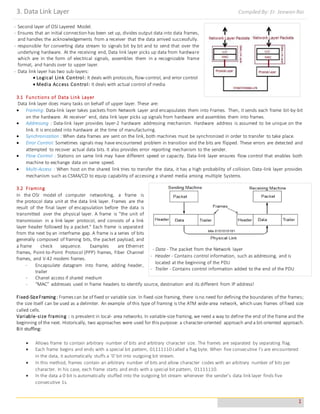
  • 1. 3. Data Link Layer Compiled By: Er. Jeewan Rai 1 - Second layer of OSI Layered Model. - Ensures that an initial connection has been set up, divides output data into data frames, and handles the acknowledgements from a receiver that the data arrived successfully. - responsible for converting data stream to signals bit by bit and to send that over the underlying hardware. At the receiving end, Data link layer picks up data from hardware which are in the form of electrical signals, assembles them in a recognizable frame format, and hands over to upper layer. - Data link layer has two sub-layers:  Logical Link Control: It deals with protocols, flow-control, and error control  Media Access Control: It deals with actual control of media 3.1 Functions of Data Link Layer Data link layer does many tasks on behalf of upper layer. These are:  Framing: Data-link layer takes packets from Network Layer and encapsulates them into Frames. Then, it sends each frame bit-by-bit on the hardware. At receiver’ end, data link layer picks up signals from hardware and assembles them into frames.  Addressing : Data-link layer provides layer-2 hardware addressing mechanism. Hardware address is assumed to be unique on the link. It is encoded into hardware at the time of manufacturing.  Synchronization : When data frames are sent on the link, both machines must be synchronized in order to transfer to take place.  Error Control: Sometimes signals may have encountered problem in transition and the bits are flipped. These errors are detected and attempted to recover actual data bits. It also provides error reporting mechanism to the sender.  Flow Control : Stations on same link may have different speed or capacity. Data-link layer ensures flow control that enables both machine to exchange data on same speed.  Multi-Access : When host on the shared link tries to transfer the data, it has a high probability of collision. Data-link layer provides mechanism such as CSMA/CD to equip capability of accessing a shared media among multiple Systems. 3.2 Framing In the OSI model of computer networking, a frame is the protocol data unit at the data link layer. Frames are the result of the final layer of encapsulation before the data is transmitted over the physical layer. A frame is "the unit of transmission in a link layer protocol, and consists of a link layer header followed by a packet." Each frame is separated from the next by an interframe gap. A frame is a series of bits generally composed of framing bits, the packet payload, and a frame check sequence. Examples are Ethernet frames, Point-to-Point Protocol (PPP) frames, Fiber Channel frames, and V.42 modem frames. - Encapsulate datagram into frame, adding header, trailer - Chanel access if shared medium - “MAC” addresses used in frame headers to identify source, destination and its different from IP address! Fixed-SizeFraming : Frames can be of fixed or variable size. In fixed-size framing, there is no need for defining the boundaries of the frames; the size itself can be used as a delimiter. An example of this type of framing is the ATM wide-area network, which uses frames of fixed size called cells. Variable-size framing : is prevalent in local- area networks. In variable-size framing, we need a way to define the end of the frame and the beginning of the next. Historically, two approaches were used for this purpose: a character-oriented approach and a bit-oriented approach. Bit stuffing:  Allows frame to contain arbitrary number of bits and arbitrary character size. The frames are separated by separating flag.  Each frame begins and ends with a special bit pattern, 01111110 called a flag byte. When five consecutive l's are encountered in the data, it automatically stuffs a '0' bit into outgoing bit stream.  In this method, frames contain an arbitrary number of bits and allow character codes with an arbitrary number of bits per character. In his case, each frame starts and ends with a special bit pattern, 01111110.  In the data a 0 bit is automatically stuffed into the outgoing bit stream whenever the sender's data link layer finds five consecutive 1s. - Data - The packet from the Network layer - Header - Contains control information, such as addressing, and is located at the beginning of the PDU - Trailer - Contains control information added to the end of the PDU
  • 2. 3. Data Link Layer Compiled By: Er. Jeewan Rai 2  This bit stuffing is similar to byte stuffing, in which an escape byte is stuffed into the outgoing character stream before a flag byte in the data.  When the receiver sees five consecutive incoming i bits, followed by a o bit, it automatically destuffs (i.e., deletes) the 0 bit. Bit Stuffing is completely transparent to network layer as byte stuffing. The figure1 below gives an example of bit stuffing.  This method of framing finds its application in networks in which the change of data into code on the physical medium contains some repeated or duplicate data. For example, some LANs encodes bit of data by using 2 physical bits. Byte stuffing:  In this method, start and end of frame are recognized with the help of flag bytes. Each frames starts with and ends with a flag byte. Two consecutive flag bytes indicate the end of one frame and start of the next one. The flag bytes used in the figure 2 used is named as “ESC” flag byte.  A frame delimited by flag bytes. This framing method is only applicable in 8-bit character codes which are a major disadvantage of this method as not all character codes use 8-bit characters e.g. Unicode.  Four example of byte sequences before and after stuffing: 3.3 Error Detection and Corrections There are many reasons such as noise, cross-talk etc., which may help data to get corrupted during transmission. The upper layers work on some generalized view of network architecture and are not aware of actual hardware data processing. Hence, the upper layers expect error-free transmission between the systems. Most of the applications would not function expectedly if they receive wrong data. Applications such as voice and video may not be that affected and with some errors they may still function well. Data-link layer uses some error control mechanism to ensure that frames (data bit streams) are transmitted with certain level of accuracy. But to understand how errors is controlled, it is essential to know what types of errors may occur. Types of Errors There may be three types of errors:  Single bit error : In a frame, there is only one bit, anywhere though, which is corrupt.
  • 3. 3. Data Link Layer Compiled By: Er. Jeewan Rai 3  Multiple bits error : Frame is received with more than one bits in corrupted state.  Burst error : Frame contains more than1 consecutive bits corrupted. Error control mechanism may involve two possible ways:  Error detection :It allows a receiver to check whether received data has been corrupted during transmission. It can, for example, request a retransmission.  Error correction : This type of error control allows a receiver to reconstruct the original information when it has been corrupted during transmission. Error Detection Errors in the received frames are detected by means of Parity Check and Cyclic Redundancy Check (CRC). In both cases, few extra bits are sent along with actual data to confirm that bits received at other end are same as they were sent. If the counter-check at receiver’ end fails, the bits are considered corrupted. Parity Check One extra bit is sent along with the original bits to make number of 1s either even in case of even parity, or odd in case of odd parity. The sender while creating a frame counts the number of 1s in it. For example, if even parity is used and number of 1s is even then one bit with value 0 is added. This way number of 1s remains even. If the number of 1s is odd, to make it even a bit with value 1 is added. The receiver simply counts the number of 1s in a frame. If the count of 1s is even and even parity is used, the frame is considered to be not-corrupted and is accepted. If the count of 1s is odd and odd parity is used, the frame is still not corrupted. If a single bit flips in transit, the receiver can detect it by counting the number of 1s. But when more than one bits are error, then it is very hard for the receiver to detect the error. Example for Parity bit :- - Suppose the sender wants to send the word “world” in ASCII the five characters are coded as 1110111 1101111 1110010 1101100 1100100 => 11101110 11011110 11100100 11011000 11001001 - Now suppose the word “world” in example 1 is received by receiver without corrupted in transmission. The receiver counts the one(1’s) in each character and comes up with even numbers (6,6,4,4,4). The data are accepted - Now suppose the word “world” in example 1 is corrupted during transmission, The receiver counts the one(1’s) in each character and comes up with even and odd numbers (7,6,5,4,4). The receiver knows that the data are corrupted, discards them and asks for re-transmission. Parity Check
  • 4. 3. Data Link Layer Compiled By: Er. Jeewan Rai 4 Cyclic Redundancy Check (CRC) CRC is a different approach to detect if the received frame contains valid data. This technique involves binary division of the data bits being sent. The divisor is generated using polynomials. The sender performs a division operation on the bits being sent and calculates the remainder. Before sending the actual bits, the sender adds the remainder at the end of the actual bits. Actual data bits plus the remainder is called a code word. The sender transmits data bits as code words. At the other end, the receiver performs division operation on code words using the same CRC divisor. If the remainder contains all zeros the data bits are accepted, otherwise it is considered as there some data corruption occurred in transit. Performance of CRC CRC is a very effective error detection method. If the divisor is chosen according to the previously mentioned rules, 1.CRC can detect all burst errors that affect an odd number of bits. 2.CRC can detect all burst errors of length less than or equal to the degree of the polynomial 3.CRC can detect, with a very high probability, burst errors of length greater than the degree of the polynomial. Checksum: The checksum is used in the Internet by several protocols although not at the data link layer. However, we briefly discuss it here to complete our discussion on error checking. To create checksum, the sender does the following :- - The unit is divided into K sections, each of n bits - Section 1 and 2 are added together using 1’s complement. - Section 3 is added to the result of the previous step. - Section 4 is added to the result of the previous step. - The process repeats until section k is added to the result of previous step. - The final result is complemented to make checksum. CRC
  • 5. 3. Data Link Layer Compiled By: Er. Jeewan Rai 5 Error Correction  An error is detected in an exchange, a negative acknowledgement NAK is returned and the specified frames are retransmitted. This process is called Automatic Repeat Request (ARQ).  Retransmission of data happens in three Cases: Damaged frame, Lost frame and Lost acknowledgement. In the digital world, error correction can be done in two ways:  Automatic repeat request (ARQ) or Backward Error Correction - When the receiver detects an error in the data received, it requests back the sender to retransmit the data unit.  Forward Error Correction (FCC) - When the receiver detects some error in the data received, it executes error-correcting code, which helps it to auto-recover and to correct some kinds of errors. The first one, Backward Error Correction, is simple and can only be efficiently used where retransmitting is not expensive. For example, fiber optics. But in case of wireless transmission retransmitting may cost too much. In the latter case, Forward Error Correction is used. To correct the error in data frame, the receiver must know exactly which bit in the frame is corrupted. To locate the bit in error, redundant bits are used as parity bits for error detection. For example, we take ASCII words (7 bits data), then there could be 8 kind of information we need: first seven bits to tell us which bit is error and one more bit to tell that there is no error. Requirements for error control mechanism:  Error detection - The sender and receiver, either both or any, must ascertain that there is some error in the transit.  Positive ACK - When the receiver receives a correct frame, it should acknowledge it.  Negative ACK - When the receiver receives a damaged frame or a duplicate frame, it sends a NACK back to the sender and the sender must retransmit the correct frame.  Retransmission: The sender maintains a clock and sets a timeout period. If an acknowledgement of a data-frame previously transmitted does not arrive before the timeout the sender retransmits the frame, thinking that the frame or it’s acknowledgement is lost in transit. Any time an error is detected in an exchange, specified frames are retransmitted. This process is called automatic repeat request (ARQ). Error control in the data link layer is based on automatic repeat request, which is the retransmission of data. There are three types of techniques available which Data-link layer may deploy to control the errors by Automatic Repeat Requests (ARQ): Stop-and-wait ARQ The following transition may occur in Stop-and-Wait ARQ:  The sender maintains a timeout counter. When a frame is sent, the sender starts the timeout counter.  If acknowledgement of frame comes in time, the sender transmits the next frame in queue.
  • 6. 3. Data Link Layer Compiled By: Er. Jeewan Rai 6  If acknowledgement does not come in time, the sender assumes that either the frame or its acknowledgement is lost in transit. Sender retransmits the frame and starts the timeout counter. If a negative acknowledgement NAK is received, the sender retransmits the frame.  The sender has to wait for an acknowledgment of every frame that it sends. Only when a acknowledgment has been received is the next frame sent. This process continues until the sender transmits an End of Transmission (EOT) frame.  Advantages of Stop and Wait: o It's simple and each frame is checked and acknowledged well.  Disadvantages of Stop and Wait: o Only one frame can be in transmission at a time. o It is inefficient, if the distance between devices is long. Reason is propagation delay is much longer than the transmission delay. o The time spent for waiting acknowledgements between each frame can add significant amount to the total transmission time.  Piggybacking:In bidirectional communications, both parties send & acknowledge data, i.e. both parties implement flow control. Outstanding ACKs are placed in the header of information frames, piggybacking can save bandwidth since the overhead from a data frame and an ACK frame (addresses, CRC, etc) can be combined into just one frame. Go-Back-N ARQ Stop and wait ARQ mechanism does not utilize the resources at their best. When the acknowledgement is received, the sender sits idle and does nothing. In Go-Back-N ARQ method, both sender and receiver maintain a window. The sending-window size enables the sender to send multiple frames without receiving the acknowledgement of the previous ones. The receiving-window enables the receiver to receive multiple frames and acknowledge them. The receiver keeps track of incoming frame’s sequence number. - When the sender sends all the frames in window, it checks up to what sequence number it has received positive acknowledgement. If all frames are positively acknowledged, the sender sends next set of frames. - If sender finds that it has received NACK or has not receive any ACK for a particular frame, it retransmits all the frames after which it does not receive any positive ACK. Selective Repeat ARQ In Go-back-N ARQ, it is assumed that the receiver does not have any buffer space for its window size and has to process each frame as it comes. This enforces the sender to retransmit all the frames which are not acknowledged. In Selective-Repeat ARQ, the receiver while keeping track of sequence numbers, buffers the frames in memory and sends NACK for only frame which is missing or damaged. The sender in this case, sends only packet for which NACK is received. Stop-and-wait ARQ Go-Back-N ARQ Selective Repeat ARQ
  • 7. 3. Data Link Layer Compiled By: Er. Jeewan Rai 7 3.4 Flow Control - In data communications, flow control is the process of managing the rate of data transmission between two nodes to prevent a fast sender from overwhelming a slow receiver. - It provides a mechanism for the receiver to control the transmission speed, so that the receiving node is not overwhelmed with data from transmitting node. - Flow control is important because it is possible for a sending computer to transmit information at a faster rate than the destination computer can receive and process it. This can happen if the receiving computers have a heavy traffic load in comparison to the sending computer, or if the receiving computer has less processing power than the sending computer. Two types of mechanisms can be deployed to control the flow:  Stop and Wait - This flow control mechanism forces the sender after transmitting a data frame to stop and wait until the acknowledgement of the data-frame sent is received. -, the receiver indicates its readiness to receive data for each frame, the message is broken into multiple frames. The sender waits for an ACK (acknowledgement) after every frame for specified time (called time out). - It is sent to ensure that the receiver has received the frame correctly. It will then send the next frame only after the ACK has been received. Operations 1. Sender: Transmits a single frame at a time. 2. Receiver: Transmits acknowledgement (ACK) as it receives a frame. 3. Sender receive ACK within time out. 4. Go to step 1. - If a frame or ACK is lost during transmission, then it has to be transmitted again by sender. This re-transmission process is known as ARQ (automatic repeat request). - The problem with Stop-and wait is that only one frame can be transmitted at a time, and that often leads to inefficient transmission, because until the sender receives the ACK it cannot transmit any new packet. During this time both the sender and the channel are unutilized.  Sliding Window - Major Drawback of Stop-and-Wait Flow Control: - Only one frame can be in transmission at a time - This leads to inefficiency if propagation delay is much longer than the transmission delay - Sliding Window Flow Control - Allows transmission of multiple frames - Assigns each frame a k-bit sequence number - Range of sequence number is [0..2k -1], i.e., frames are counted modulo 2k - In this flow control mechanism, both sender and receiver agree on the number of data-frames after which the acknowledgement should be sent. As we learnt, stop and wait flow control mechanism wastes resources, this protocol tries to make use of underlying resources as much as possible. - A method of flow control in which a receiver gives a transmitter permission to transmit data until a window is full. When the window is full, the transmitter must stop transmitting until the receiver advertises a larger window.[5] - Sliding-window flow control is best utilized when the buffer size is limited and pre-established. During a typical communication between a sender and a receiver the receiver allocates buffer space for n frames (n is the buffer size in frames). The sender can send and the receiver can accept n frames without having to wait for an acknowledgement. - A sequence number is assigned to frames in order to help keep track of those frames which did receive an acknowledgement. - The receiver acknowledges a frame by sending an acknowledgement that includes the sequence number of the next frame expected. This acknowledgement announces that the receiver is ready to receive n frames, beginning with the number specified. - Both the sender and receiver maintain what is called a window. The size of the window is less than or equal to the buffer size. Sliding window flow control has a far better performance than stop-and-wait flow control. For example, in a wireless environment if data rates are low and noise level is very high, waiting for an acknowledgement for every packet that is transferred is not very feasible. Therefore, transferring data as a bulk would yield a better performance in terms of higher throughput. The window maintained by the sender indicates which frames he can send. The sender sends all the frames in the window and waits for an acknowledgement (as opposed to acknowledging after every frame). The sender then shifts the window to the corresponding sequence number, thus indicating that frames within the window starting from the current sequence number can be sent. Stop and Wait
  • 8. 3. Data Link Layer Compiled By: Er. Jeewan Rai 8 How Flow control is achieved? • Receiver can control the size of the sending window. • By limiting the size of the sending window data flow from sender to receiver can be limited . The example assumes a 3-bit sequence number field and a maximum windowsize of 2n-1=7 frames. Initially, Source and Destination have windows indicating that Source may transmit seven frames, beginning with frame 0 (FO). After transmitting three frames (FO, F1, F2) without acknowledgment, Source has contracted its window to four frames. The window indicates that Source may transmit four frames, beginning with frame number 3. Destination then transmits an RR (receive-ready) 3(RR3), which means: "I have received all frames up to frame number 2(F2) and am ready to receive frame number 3(F3); in fact, I am prepared to receive seven frames, beginning with frame number 3(F3)." With this acknowledgment, Source is back up to permission to transmit seven frames, still beginning with frame 3(F3). Source proceeds to transmit frames 3, 4, 5 , and 6. Destination returns an RR 7, which allows Source to send up to and including frame F2. MaximumWindow Size =7
  • 9. 3. Data Link Layer Compiled By: Er. Jeewan Rai 9 3.5 Examples of Protocol : HDLC, PPP *HDLC : HDLC (High-level Data Link Control) is a group of protocols or rules for transmitting data between network points (sometimes called nodes). In HDLC, data is organized into a unit (called a frame) and sent across a network to a destination that verifies its successful arrival. The HDLC protocol also manages the flow or pacing at which data is sent. Variations of HDLC are also used for the public networks that use the X.25communications protocol and for frame relay, a protocol used in both and wide area network, public and private. There are three types of HDLC frames:  Information frames/User data (I-frames) : carry user's data and control information about user's data. The first bit of control field is always zero, i.e. the presence of zero at this place indicates that it is I-frame.  Supervisory frames/Control data (S-frames) : carries control information, primarily data link layer flow and error controls. It does not contain information field. The first two bits in the control field of S-frame are always 10.  Unnumbered frames (U-frames) : are used to exchange session management and control information between the two connected devices. Information field in U-frame does not carry user information rather, it carries system management information. U-frame is identified by the presence of 11 in the first and second bit position in control field. N(S) = specifies the sequence number of the frame. P/F i.e. Poll/Final = used for these two purposes. It has, meaning only when it is set i.e. when P/F=1. It can represent the following two cases. (i) It means poll when frame is sent by a primary station to secondary (when address field contains the address of receiver). (ii) It means final when frame is sent by secondary to a primary (when the address field contains the address of the sender). N(R) i.e. the sequence number of the frame expected in return in two-way communication. If last frame received was error-free then N(R) number will be that of the next frame is sequence. If the last frame was not received correctly, the N(R) number will be the number of the damaged frame, asking for its retransmission. Flag Field: Flag fields delimit the frame at both ends with the unique pattern 01111110.A single flag may be used as the closing flag for one frame and the opening flag for the next. On both sides of the user-network interface, receivers are continuously hunting for the flag sequence to synchronize on the start of a frame. While receiving a frame, a station continues to hunt for that sequence to determine the end of the frame. Since the pattern 01111110 may appear in the frame as well, aprocedure know and bit stuffing is used. After detecting a starting flag, the receiver monitors the bit stream. When a pattern of five 1s appears, the sixth bit is examined. If this bit is 0, it is deleted. If the sixth bit is a 1 and the seventh bit is a 0, the combination is accepted as a flag. If the sixth and seventh bits are both 1, the sender is indicating an abort condition. With the use of bit stuffing, arbitrary bit patterns can be inserted into the data field of the frame. This property is known as data transparency. Address Field: The address field identifies the secondary station that transmitted or is to receive the frame. This field is not needed for point-to-point links, but is always included for the sake of uniformity. Control Field: It defines the three types of frames I,U and S Frame for HDLC. Information Field: This field is present only in I frame and some U Frame. Frame Check Sequence Field: Its and error detecting code calculated from the remaining bits of the frame, exclusive of flags. The normal code is 16 bit CRC code. HDLC is a cisco proprietary while PPP is an open standard (used on different router)
  • 10. 3. Data Link Layer Compiled By: Er. Jeewan Rai 10 *PPP :In computer networking, Point-to-Point Protocol (PPP) is a data link (layer 2) protocol used to establish adirect connection between two nodes. It can provide connection authentication, transmission encryption (using ECP, RFC 1968), and compression. PPP connections are used to connect LANs to service provider WANs, and to connect LAN segments within an organisation network. A LAN- to-WAN point-to-point connection is also referred to as a serial connection or leased-line connection, because the lines are leased from a carrier (usually a telephone company) and are dedicated for use by the company leasing the lines. PPP is used over many types of physical networks including serial cable, phone line, trunk line, cellular telephone, specialized radio links, and fiber optic links such as SONET. PPP is also used over access connections. Internet service providers (ISPs) have used PPP for customer dial-up access to the Internet, since IP packets cannot be transmitted over a modem line on their own, without some data link protocol. PPP is used to carry outthe followingfunctions: -Data Encapsulations:this is amethod used to encapsulatemulti-protocol datagrams.Differentnetwork-layerprotocols aresimultaneously transported and encapsulated overthe same link,the flexibility of thePPP design enables itto be compatibleto mostsupportingnetwork devices. -Link Control Protocol:TheLCP is used to establish,configure,and testthe data link connection.It’s flexiblein handlingdifferentsizes of packets,detect alooped-back link,configuration errors,and terminate the link. -Network Control Protocol:NCP is used forestablishingand configuringdifferentNetwork layerprotocols.PPP enables thesimultaneous useof multipleNetwork layer protocols. Someof themore familiar NCPs are: Internet Protocol Control Protocol, AppleTalk Control Protocol, Cisco Systems Control Protocol Fig. PPP Frame Format Flag.APPP frame starts and ends with a I-byte flag with the bit pattern 01111110.Although this pattern is the same as that used in HDLC, there is a big difference. PPP is a byte-oriented protocol; HDLC is a bit-oriented protocol. The flag is treated as a byte, as we will explain later. Address. The address field in this protocol is a constant value and set to 11111111 (broadcast address). During negotiation (discussed later), the two parties may agree to omit this byte. Control. This field is set to the constant value 11000000 (imitating unnumbered frames in HDLC). As we will discuss later, PPP does not provide any flow control. Error control is also limited to error detection. This means that this field is not needed at all, and again, the two parties can agree, during negotiation, to omit this byte. Protocol.The protocol field defines what is being carried in the data field: either user data or other information. We discuss this field in detail shortly. This field is by default 2 bytes long, but the two parties can agree to use only 1 byte. Payload field. This field carries either the user data or other information. The data field is a sequence of bytes with the default of a maximum of 1500 bytes; but this can be changed during negotiation. The data field is byte- stuffed if the flag byte pattern appears in this field. Because there is no field defining the size of the data field, padding is needed if the size is less than the maximum default value or the maximum negotiated value. FCS. The frame check sequence (FCS) is simply a 2-byte or 4-byte standard CRC. 3.6 The Media Access Sub Layer In the Open Systems Interconnection (OSI) model of communication, the Media Access Control layer is one of two sublayers of the Data Link Control layer and is concerned with sharing the physical connection to the network among several computers. Each computer has its own unique MAC address. Ethernet is an example of a protocol that works at the Media Access Control layer level. MAC is responsible for the transmission of data packets to and from the network-interface card, and to and from another remotely shared channel. What MAC layer does? (1) (ON SENDERS END )It receives packet form network layer and attach header to it, header includes 48 bit MAC address (which is unique to each machine provided by manufacturer unlike IP address which is provided by network provider ) , includes Error correction bits also (2) (ON RECIVERS END )It receives frame from physical layer, verify if frame has destination MAC address of this computer only if yes accept that frame, removes frame header and forward remaining pay load to Network layer (3) It also ensures a collision free transmission of frames in some of the protocol like 802.3 or 802.11 The primary functions performed by the MAC layer are: - acts as an interface between the Logical Link Control sublayer and the network's physical layer
  • 11. 3. Data Link Layer Compiled By: Er. Jeewan Rai 11 - provides an addressing mechanism called physical address or MAC address. This is a unique serial number assigned to each network adapter, making it possible to deliver data packets to a destination within a subnetwork, i.e. a physical network without routers, for example an Ethernet network. - provides the protocol and control mechanisms that are required for a certain channel access method. This makes it possible for several stations connected to the same physical medium to share it. Examples of shared physical medium are bus networks, ring networks, hub networks, wireless networks and half-duplex point-to-point links. Following Protocols are used by Medium Access Layer : ALOHA : ALOHA is a system for coordinating and arbitrating access to a shared communication channel. Carrier Sensed Multiple Access (CSMA) : CSMA is a network access method used on shared network topologies such as Ethernet to control access to the network. CSMA/CD (Carrier Sense Multiple Access/Collision Detection) : CD (collision detection) defines what happens when two devices sense a clear channel, then attempt to transmit at the same time. CSMA/CA (Carrier Sense Multiple Access/Collision Avoidance) : In CA collision avoidance), collisions avoided because each node signals its intent to transmit before actually doing so. Ethernet : IEEE 802.3 Local Area Network (LAN) Protocols : Ethernet protocols refer to the family of local-area network (LAN)covered by the IEEE 802.3. IEEE 802.4 Token Bus : In token bus network station must have control of a token before it can transmit on the network. The IEEE 802.4 Committee has defined token bus standards as broadband networks, as opposed to Ethernet's baseband transmission technique. Th e topology of the network can include groups of workstations connected by long trunk cables. IEEE 802.5 Token Ring : Token ring is the IEEE 802.5 standard for a token-passing ring network with a star-configured physical topology 3.7 Channel Allocation Problem - The Channel Allocation Problem is how to allocate a single broadcast channel among competing users. - Mobile Wireless Communication Systems experience a rapid increase in the number of subscribers - Need for reliable and efficient operations - Limited radio resources - channels Static Channel Allocation( Synchronous) in LANs and MANs With static Channel Allocation, a specific capacity is dedicated to a connection; this is the same approach used in circuit switching, frequency-division multiplexing (FDM), and synchronous time-division multiplexing (TDM). Such techniques are generally not optimal in LANs and MANS because the needs of the stations are unpredictable. If any connection is not transferring information, then the channel is wasted which is allocated to particular connection. Therefore it is better for bulky and heavy data. i. The traditional way of allocating a single channel, such as a telephone trunk, among multiple competing users is Frequency Division Multiplexing (FDM). If there are N users, the bandwidth is divided into N equal-sized portions each user being assigned one portion. Since each user has a private frequency band, there is no interference between users. ii. When there are only a small and constant number of users, each of which has a heavy (buffered) load of traffic (e.g., carriers' switching offices), FDM is a simple and efficient allocation mechanism. However, when the number of senders is large and continuously varying or the traffic is bursty, FDM presents some problems. iii. If the spectrum is cut up into N regions and fewer than N users are currently interested in communicating, a large piece of valuable spectrum will be wasted. If more than N users want to communicate, some of them will be denied permission for lack of bandwidth, even if some of the users who have been assigned a frequency band hardly ever transmit or receive anything. Dynamic Channel Allocation (Asynchronous) In dynamic channel allocation, capacity is given whenever there is any need. It is divided into 3 groups, a)ROUND ROBIN: With round robin each turn is given the opportunity to transmit. During that opportunity the station may decline to transmit or may transmit subject to a specific upper bound. When many stations have data to transmit, round robin technique can be efficient. If only a few stations have data to transmit, then, there is a considerable overhead in passing the turn from station to station, because most of the stations can’t transmit but simply pass their turns. b) RESERVATION: It is used for stream traffic, in reservation techniques time on the medium is divided into slots, much as with TDM. Reservation can be made in centralized or distributed fashion. c) CONTENTION:
  • 12. 3. Data Link Layer Compiled By: Er. Jeewan Rai 12 It is used for bursty traffic, with contention, no control is exercised to determine whose turn it is, all stations contend for time in a way that can be. 3.8 Multiple Access Protocol we noted that there are two types of network links: point-to-point links, and broadcast links. A point-to-point link consists of a single sender on one end of the link, and a single receiver at the other end of the link. Many link-layer protocols have been designed for point- to-point links; PPP (the point-to-point protocol) and HDLC are two such protocols The second type of link, a broadcast link, can have multiple sending and receiving nodes all connected to the same, single, shared broadcast channel. The term "broadcast" is used here because when any one node transmits a frame, the channel broadcasts the frame and each of the other nodes receives a copy.Ethernet is probably the most widely deployed broadcast link technology first examine a problem of central importance to the data link layer: how to coordinate the access of multiple sending and receiving nodes to a shared broadcast channel - the so-called multiple access problem. Broadcast channels are often used in local area networks (LANs), networks that are geographically concentrated in a single building (or on a corporate or university campus). Taxonomy of Multiple Access Protocols Random Access Protocols - When node has packet to send o transmit at full channel data rate R. o no a priori coordination among nodes - If two or more nodes “collide”, they retransmit at random times - random access MAC protocol specifies: o how to detect collisions o how to recover from collisions (e.g., via delayed retransmissions) - Examples of random access MAC protocols: o slotted ALOHA o ALOHA o CSMA and CSMA/CD Controlled Access Protocols In controlled access, the stations consult one another to find which station has the right to send. A station cannot send unless it has been authorized by other stations. The three popular controlled-access methods are as follows. 1. Reservation: In the reservation method, a station needs to make a reservation before sending data. Time is divided into intervals. In each interval, a reservation frame precedes the data frames sent in that interval. If there are N stations in the system, there are exactly N reservation minislots in the reservation frame. Each minislot belongs to a station. When a station needs to send a data frame, it makes a reservation in its own minislot. The stations that have made reservations can send their data frames after the reservation frame. The following figure shows a situation with five stations and a five-minislot reservation frame. In the first interval, only stations 1, 3, and 4 have made reservations. In the second interval, only station 1 has made a reservation. 2. Polling: Polling works with topologies in which one device is designated as a primary station and the other devices are secondary stations. All data exchanges must be made through the primary device even when the ultimate destination is a secondary device. Random access Protocols Aloha Protocols Carrier Sense Multiple Access Protocol Carrier Sense Multiple Access with Collision Detection
  • 13. 3. Data Link Layer Compiled By: Er. Jeewan Rai 13 The primary device controls the link; the secondary devices follow its instructions. It is up to the primary device to determine which device is allowed to use the channel at a given time. The primary device, therefore, is always the initiator of a session. Consider the following figure. If the primary wants to receive data, it asks the secondaries if they have anything to send, this is called poll function. If the primary wants to send data, it tells the secondary to get ready to receive; this is called select function. Select: The select function is used whenever the primary device has something to send. If it has something to send, the primary device sends it. It has to know whether the target device is prepared to receive or not. So the primary must alert the secondary to the upcoming transmission and wait for an acknowledgment of the secondary's ready status. Before sending data, the primary creates and transmits a select (SEL) frame, one field of which includes the address of the intended secondary. Poll: The poll function is used by the primary device to solicit transmissions from the secondary devices. When the primary is ready to receive data, it must ask (poll) each device in turn if it has anything to send. When the first secondary is approached, it responds either with a NAK frame if it has nothing to send or with data (in the form of a data frame) if it does. If the response is negative (a NAK frame), then the primary polls the next secondary in the same manner until it finds one with data to send. When the response is positive (a data frame), the primary reads the frame and returns an acknowledgment (ACK frame), verifying its receipt. 3. Token Passing: In the token-passing method, the stations in a network are organized in a logical ring. In other words, for each station, there is a predecessor and a successor. The predecessor is the station which is logically before the station in the ring; the successor is the station which is after the station in the ring. The current station is the one that is accessing the channel now. The right to this access has been passed from the predecessor to the current station. The right will be passed to the successor when the current station has no more data to send. In this method, a special packet called a token circulates through the ring. The possession of the token gives the station the right to access the channel and send its data. When a station has some data to send, it waits until it receives the token from its predecessor. It then holds the token and sends its data. When the station has no more data to send, it releases the token, passing it to the next logical station in the ring. The station cannot send data until it receives the token again in the next round. Token management is needed for this access method. Stations must be limited in the time they can have possession of the token. The token must be monitored to ensure it has not been lost or destroyed. For example, if a station that is holding the token fails, the token will disappear from the network. Another function of token management is to assign priorities to the stations and to the types of data being transmitted. And finally, token management is needed to make low- priority stations release the token to high priority stations. Logical Ring: In a token-passing network, stations do not have to be physically connected in a ring; the ring can be a logical one. The following figure show four different physical topologies that can create a logical ring.
  • 14. 3. Data Link Layer Compiled By: Er. Jeewan Rai 14 • In the physical ring topology, when a station sends the token to its successor, the token cannot be seen by other stations; the successor is the next one in line. This means that the token does not have to have the address of the next successor. The problem with this topology is that if one of the links-the medium between two adjacent stations fails, the whole system fails. • The dual ring topology uses a second (auxiliary) ring which operates in the reverse direction compared with the main ring. The second ring is for emergencies only. If one of the links in the main ring fails, the system automatically combines the two rings to form a temporary ring. After the failed link is restored, the auxiliary ring becomes idle again. • In the bus ring topology, also called a token bus, the stations are connected to a single cable called a bus. They, however, make a logical ring, because each station knows the address of its successor (and also predecessor for token management purposes). When a station has finished sending its data, it releases the token and inserts the address of its successor in the token. Only the station with the address matching the destination address of the token gets the token to access the shared media. The Token Bus LAN, standardized by IEEE, uses this topology. • In a star ring topology, the physical topology is a star. There is a hub, however, that acts as the connector. The wiring inside the hub makes the ring; the stations are connected to this ring through the two wire connections. This topology makes the network less prone to failure because if a link goes down, it will be bypassed by the hub and the rest of the stations can operate. Also adding and removing stations from the ring is easier. This topology is still used in the Token Ring LAN designed by IBM. – Predetermined allocation (TDMA) – Reservation protocols – Token passing protocols 3.10 Networks *Fiber Distributed Data Interface (FDDI) • FDDI is a high performance token ring LAN based on optical fibers • ANSI standard X3T9.5 • Data rates of 100 MBit/s • Range of up to 200 km (MAN?) • Support of up to 1000 stations, with distances of maximally 2 km • Often used as Backbone for small LANs • Successor: FDDI-II, supports besides normal data also synchronous circuit switched PCM data (speech) and ISDN traffic • Variant: CDDI (Copper Distributed Data Interface), with 100 MBit/s over Twisted Pair Structure of FDDI Wiring within FDDI: 2 optical fiber rings with opposite transmission direction. • During normal operation, only the primary ring is used, the secondary ring remains in readiness • If the ring breaks, the other one (also called protection ring) can be used. • If both rings break or if a station precipitates, the rings can be combined into only one, which has double length:
  • 15. 3. Data Link Layer Compiled By: Er. Jeewan Rai 15 Two classesof stations exist:DAS (Dual Attachment Station) can be attached to both rings,the cheaper SAS (SingleAttachment Station) areonly attached to one ring. FDDI Configuration TransmissionwithinFDDI Coding : 4B/5B code, thus coding of 4 bits of data in 5 bits which are transferred Synchronization : Transmission of a long preamble in order to synchronize the receiver to the sender clock pulse. The clocks of all stations must run stable on at least 0.005%. With such a stability, frames with up to 4500 byte of data can be transferred without the receiver losing the clock pulse. Protocols : The fundamental protocols of FDDI are similar to IEEE 802.5 (token ring): in order to transmit data, a station must acquire the token. Then it transfers its frame and takes it from the ring when it returns to it. Due to the expansion of FDDI, a single token is unpractical. Therefore, FDDI transfers in the multiple token mode. FDDI Frame Format FDDI that is completely compatible with the ANSI standard version.  Preamble---A unique sequence that prepares each station for an upcoming frame.  Start Delimiter---Indicates the beginning of a frame by employing a signaling pattern that differentiates it from the rest of the frame.  Frame Control---Indicates the size of the address fields and whether the frame contains asynchronous or synchronous data, among other control information.  Destination Address--- Contains a unicast (singular), multicast (group), or broadcast (every station) address. As with Ethernet and Token Ring addresses, FDDI destination addresses are 6 bytes long.
  • 16. 3. Data Link Layer Compiled By: Er. Jeewan Rai 16  Source Address---Identifies the single station that sent the frame. As with Ethernet and Token Ring addresses, FDDI source addresses are 6 bytes long.  Data---Contains either information destined for an upper-layer protocol or control information.  Frame Check Sequence (FCS)---Filed by the source station with a calculated cyclic redundancy check value dependent on frame contents (as with Token Ring and Ethernet). The destination address recalculates the value to determine whether the frame was damaged in transit. If so, the frame is discarded.  End Delimiter---Contains unique symbols, which cannot be data symbols, that indicate the end of the frame.  Frame Status---Allows the source station to determine whether an error occurred and whether the frame was recognized and copied by a receiving station. * Ethernet - IEEE has standardized a number of LANs and MANs under the name of IEEE 802. A few have survived but many have not. - The most important of the survivors are 802.3 (Ethernet) and 802.11 (wireless LAN) - For 802.15 (Bluetooth) and 802.16 (wireless MAN), it is too early to tell. - Both 802.3 and 802.11 have different physical layers and different MAC sublayers but converge on the same logical link contro l sublayer (defined in 802.2), so they have the same interface to the network layer. Ethernet Cabling Name Cable Max seg.(m) Nodes per segment Advantages 10Base5 thick coax 500 100 The Original 10Base2 thin coax 185 30 no hub 10Base-T twisted pair (UTP) 100 1024 cheapest 10Base-F fiber 2000 1024 long distance Ethernet Frame Format - Preamble: Sequence of 10101010s. 8 bytes. o (SOF, Start of Frame delimiter, for compatibility with 802.4 and 802.5) - Addresses: 2 or 6 bytes. 10Base5 10Base2 10Base-T DIX (DEC, Intel, Xerox) IEEE 802.3
  • 17. 3. Data Link Layer Compiled By: Er. Jeewan Rai 17  high-order bit of the destination address:  0 for ordinary addresses  1 for group addresses.  bit 46 - global or local address. - Type: specifies which process to give the frame to. o (Any number <=1500 is treated as length or as type otherwise.) - Data: up to 1500 bytes. - Pad: (optional) The frame must be at least 64 bytes in total! - Checksum: CRC based on this polynomial: x32+x26+x23+x22+x16+x12+x11+x10+x8+x7+x5+x4+x2+x+1 *ALOHA ALOHA is a system for coordinating and arbitrating access to a shared communication Networks channel. It was developed in the 1970s by Norman Abramson and his colleagues at the University of Hawaii. The original system used for ground based radio broadcasting, but the system has been implemented in satellite communication systems. A shared communication system like ALOHA requires a method of handling collisions that occur when two or more systems attempt to transmit on the channel at the same time. In the ALOHA system, a node transmits whenever data is available to send. If another node transmits at the same time, a collision occurs, and the frames that were transmitted are lost. However, a node can listen to broadcasts on the medium, even its own, and determine whether the frames were transmitted. Aloha means "Hello". Aloha is a multiple access protocol at the datalink layer and proposes how multiple terminals access the medium without interference or collision. In 1972 Roberts developed a protocol that would increase the capacity of aloha two fold. The Slotted Aloha protocol involves dividing the time interval into discrete slots and each slot interval corresponds to the time period of one frame. This method requires synchronization between the sending nodes to prevent collisions. There are two different versior.s/types of ALOHA: (i) Pure ALOHA In pure ALOHA, the stations transmit frames whenever they have data to send. • When two or more stations transmit simultaneously, there is collision and the frames are destroyed. • In pure ALOHA, whenever any station transmits a frame, it expects the acknowledgement from the receiver. • If acknowledgement is not received within specified time, the station assumes that the frame (or acknowledgement) has been destroyed. • If the frame is destroyed because of collision the station waits for a random amount of time and sends it again. This waiting time must be random otherwise same frames will collide again and again. • Therefore, pure ALOHA dictates that when time-out period passes, each station must wait fora randomamount of time before resending its frame. This randomness will help avoid more collisions. • Figure shows an example of frame collisions in pure ALOHA. • In fig there are four stations that. contended with one another for access to shared channel. All these stations are transmitting frames. Some of these frames collide because multiple frames are in contention for the shared channel. Only two frames, frame 1.1 and frame 2.2 survive. All other frames are destroyed. • Whenever two frames try to occupy the channel at the same time, there will be a collision and both will be damaged. If first bitof a new frame overlaps with just the last bit of a frame almost finished, both frames will be totally destroyed and both will have to be retransmitted.
  • 18. 3. Data Link Layer Compiled By: Er. Jeewan Rai 18 (ii) Slotted ALOHA • Slotted ALOHA was invented to improve the efficiency of pure ALOHA as chances of collision in pure ALOHA are very high. • In slotted ALOHA, the time of the shared channel is divided into discrete intervals called slots. • The stations can send a frame only at the beginning of the slot and only one frame is sent in each slot. • In slotted ALOHA, if any station is not able to place the frame onto the channel at the beginning of the slot i.e. it misses the time slot then the station has to wait until the beginning of the next time slot. • In slotted ALOHA, there is still a possibility of collision if two stations try to send at the beginning of the same time slot as shown in fig. • Slotted ALOHA still has an edge over pure ALOHA as chances of collision are reduced to one-half. *VLAN - Virtual local area network - It is a logical group of workstations, servers and network devices that appear to be on the same LAN despite their geographical distribution. A VLAN allows a network of computers and users to communicate in a simulated environment as if they exist in a single LAN and are sharing a single broadcast and multicast domain. - systems on one VLAN don't see the traffic associated with systems on other VLANs on the same network. - VLANs allow network administrators to partition their networks to match the functional and security requirements of their systems without having to run new cables or make major changes in their current network infrastructure - Ports on switches can be assigned to one or more VLANs, allowing systems to be divided into logical groups -- e.g., based on which department they are associated with -- and rules to be established about how systems in the separate groups are allowed to communicate with each other. To understand VLAN more clearly let's take an example.  Our company has three offices.  All offices are connected with back links.  Company has three departments Development, Production and Administration.  Development department has six computers.  Production department has three computers.  Administration department also has three computers.  Each office has two PCs from development department and one from both production and administratio n department.  Administration and production department have sensitive information and need to be separate from development department. With default configuration, all computers share same broadcast domain. Development department can access the administration or production department resources. With VLAN we could create logical boundaries over the physical network. Assume that we created three VLANs for our network and assigned them to the related computers.  VLAN Ad mi n for Administration department  VLAN D ev for Development department  VLAN P ro for Production department Physically we changed nothing but logically we grouped devices according to their function. These groups [VLANs] need router to communicate with each other. Logically our network look likes following diagram.
  • 19. 3. Data Link Layer Compiled By: Er. Jeewan Rai 19 Fig . Same LAN with Different Departments Fig. Different LAN with Different Departments With the help of VLAN, we have separated our single network in three small networks. These networks do not share broadcast with each other improving network performance. VLAN also enhances the security. Now Development department cannot access the Administration and Production department directly. Different VLAN can communicate only via Router where we can configure wild range of security options. VLAN membership can be assigned to a device by one of two methods. These methods decide how a switch will associate its ports with VLANs. Static : AssigningVLANs statically is the most common and secure method. It is pretty easy to set up and supervise. In this method we manually assign VLAN to switch port. VLANs configured in this way are usually known as port-based VLANs. Static method is the most secure method also. As any switch port that we have assigned a VLAN will keep this association always unless we manually change it. It works really well in a networking environment where any user movement within the network needs to be controlled. Dynamic : In dynamic method, VLANs are assigned to port automatically depending on the connected device. In this method we have configure one switch from network as a server. Server contains device specific information like MAC address, IP address etc. This information is mapped with VLAN. Switch acting as server is known as VMPS (VLAN Membership Policy Server). Only high end switch can configured as VMPS. Low end switch works as client and retrieve VLAN information from VMPS. Dynamic VLANs supports plug and play movability. For example if we move a PC from one port to another port, new switch port will automatically be configured to the VLAN which the user belongs. In static method we have to do this process manually. Why use VLAN's? VLAN's offer a number of advantages over traditional LAN's. They are: 1) Performance : In networks where traffic consists of a high percentage of broadcasts and multicasts, VLAN's can reduce the need to send such traffic to unnecessary destinations. For example, in a broadcast domain consisting of 10 users, if the broadcast traffic is intended only for 5 of the users, then placing those 5 users on a separate VLAN can reduce traffic 2) Formation of Virtual Workgroups : Nowadays, it is common to find cross-functional product development teams with members from different departments such as marketing, sales, accounting,and research. These workgroups are usually formed for a short period of time. During this period, communication between members of the workgroup will be high. To contain broadcasts and multicasts within the workgroup, a VLAN can be set up for them.
  • 20. 3. Data Link Layer Compiled By: Er. Jeewan Rai 20 3) Simplified Administration : Seventy percent of network costs are a result of adds, moves, and changes of users in the network [ Buerger]. Every time a user is moved in a LAN, recalling, new station addressing, and reconfiguration of hubs and routers becomes necessary. Some of these tasks can be simplified with the use of VLAN's. 4) Reduced Cost : VLAN's can be used to create broadcast domains which eliminate the need for expensive routers. 5) Security : Periodically, sensitive data may be broadcast on a network. In such cases, placing only those users who can have access to that data on a VLAN can reduce the chances of an outsider gaining access to the data. VLAN's can also be used to control broadcast domains, set up firewalls, restrict access, and inform the network manager of an intrusion *Carrier Sense Multiple Access/Collision Detect (CSMA/CD) - Carrier sense is the ability of a network interface card (NIC) to check the network for any communication. Obviously if there is data being transmitted over the network, the NIC should not attempt to transmit data. If there is no traffic on the network, the NIC will then attempt to transmit the data. - The MA (multiple access) part of CSMA/CD tells us that there will be multiple devices using the same network. This, of course, means collisions are more than possible. - The CD (collision detect) part of CSMA/CD states that we need a method for detecting a collision. After all, we need to tell other computers to hold off on transmissions until the problem is sorted. Collisions can be spotted since they are generally higher in signal amplitude than normal signals. If we do indeed spot a collision, a jamming signal is sent to all computers and a back-off algorithm is observed. This algorithm simply tells computers not to transmit new data for a random amount of time. - CSMA/CD is a protocol in which the station senses the carrier or channel before transmitting frame just as in ready and not-ready CSMA Applications : Now-obsolete shared media Ethernet variants (10BASE5, 10BASE2) and in the early versions of twisted-pair Ethernet which used repeater hubs. Modern Ethernet networks, built with switches and full-duplex connections Frame format of CSMA/CD The frame format specified by IEEE 802.3 standard contains following fields. 1. Preamble:It is seven bytes (56 bits) that provides bit synchronization. It consists of alternating Os and 1s. The purpose is to provide alert and timing pulse. 2. Start Frame Delimiter (SFD): It is one byte field with unique pattern: 10 10 1011. It marks the beginning of frame. 3. Destination Address (DA): It is six byte field that contains physical address of packet's destination. 4. Source Address (SA): It is also a six byte field and contains the physical address of source or last device to forward the packet (most recent router to receiver). 5. Length: This two byte field specifies the length or number of bytes in data field. 6. Data: It can be of 46 to 1500 bytes, depending upon the type of frame and the length of the information field. 7. Frame Check Sequence (FCS): This for byte field contains CRC for error detection. *IEEE 802.3 (Ethernet) IEEE 802.3 is aworking group and a collection of IEEE standards produced by the working group defining the physical layer and data link layer's media access control (MAC) of wired Ethernet. This is generally a local area network technology with some wide area network applications. Physical connections are made between nodes and/or infrastructure devices (hubs, switches, routers) by various types of copper or fiber cable. 802.3 is a technology that supports the IEEE 802.1 network architecture. 802.3 also defines LAN access method using CSMA/CD. Fig. Carrier Sense Fig. Multiple Access Fig. Collision Detect
  • 21. 3. Data Link Layer Compiled By: Er. Jeewan Rai 21 802.3 is a standard specification for Ethernet, a method of physical communication in a local area network (LAN), which is maintained by the Institute of Electrical and Electronics Engineers (IEEE). In general, 802.3 specifies the physical media and the working characteristics of Ethernet. The original Ethernet supports a data rate of 10 megabits per second (Mbps) and specifies these possible physical media:  0BASE-2 (Thin wire coaxial cable with a maximum segment length of 185 meters)  10BASE-5 (Thick wire coaxial cable with a maximum segment length of 500 meters)  10BASE-F (optical fiber cable)  10BASE-T (ordinary telephone twisted pair wire)  10BASE-36 (broadband multi-channel coaxial cable with a maximum segment length of 3,600 meters) This designation is an IEEE shorthand identifier. The "10" in the media type designation refers to the transmission speed of 10 Mbps. The "BASE" refers to baseband signaling, which means that only Ethernet signals are carried on the medium (or, with 10BASE-36, on a single channel). The "T" represents twisted-pair; the "F" represents fiber optic cable; and the "2", "5", and "36" refer to the coaxial cable segment length (the 185 meter length has been rounded up to "2" for 200). *Token Bus (IEEE 802.4) - The 802.4 IEEE standard defines the Token Bus protocol, combines features of Ethernet (Bus Topology) and Token Ring. - Stations are logically organized into a ring. A token is passed among the stations. If a station wants to send data, it must wait and take the token - The logical ring is formed based on the MAC address of the station in descending order. - Each station considers the immediate lower address as next station and the station with immediate higher as the previous station. Example : Fig. A Token Bus network Frame format of Token Bus The various fields present in the frame format are 1. Preamble: This. Field is at least 1 byte long. It is used for bit synchronization. 2. Start Delimiter: This one byte field marks the beginning of frame. 3. Frame Control: This one byte field specifies the type of frame. It distinguishes data frame from control frames. For data frames it carries frame's priority. For control frames, it specifies the frame type. The control frame types include. token passing and various ring maintenance frames, includingthe mechanism for letting new station enter the ring, the mechanism for allowing stations to leave the ring. 4. Destination address: It specifies 2 to 6 bytes destination address. 5. Source address: It specifies 2 to 6 bytes source address. 6. Data: This field may be upto 8182 bytes long when 2 bytes addresses are used & upto 8174 bytes long when 6 bytes address is used. 7. Checksum: This 4 byte field detects transmission errors. 8. End Delimiter: This one byte field marks the end of frame. *Token Ring (IEEE 802.5) - It requires that stations take turns to send data - Each station may transmit only during its turn and may send only one frame during each turn. - The mechanism that coordinates this rotation is called token passing. - Token travel along the ring basis.
  • 22. 3. Data Link Layer Compiled By: Er. Jeewan Rai 22 Frame format Two basic frame types are used - tokens, and data/command frames. The token is three bytes long and consists of a start delimiter, an access control byte, and an end delimiter. The format of the token is shown below. The Token Ring token A data/command frame has the same fields as the token, plus several additional fields. The format of the data/command frame is shown below. The Token Ring frame format  Start delimiter - alerts each station of the arrival of a token or frame.  Access control byte - contains the priority field, the reservation field, the token bit and a monitor bit.  Frame control byte - indicates whether the frame contains data or control information. In a control frame, this byte specifies the type of control information carried.  Destination and source addresses - two six-byte fields that identify the destination and source station MAC addresses.  Data - the maximum length is limited by the ring token holding time, which defines the maximum time a station can hold the token  Frame check sequence (FCS) - filled by the source station with a calculated value dependent on the frame contents. The destination station recalculates the value to determine whether the frame was damaged in transit. If so, the frame is discarded.  End delimiter - signals the end of the token or frame, and contains bits that may be used to indicate a damaged frame, and to identify the last frame in a logical sequence.  Frame status - a one-byte field that terminates a frame, and includes the one-bit address- recognized and frame-copied fields. These one-bit fields, if set, provide confirmation that the frame has been delivered to the source address and the data read. Both fields are duplicated within the frame status byte.
  • 23. 3. Data Link Layer Compiled By: Er. Jeewan Rai 23 *802.11 IEEE wireless LAN standards 802.11 and 802.11xrefers to a family of specifications developed by the IEEE for wireless LAN (WLAN) technology. 802.11 specifies an over-the-air interface between a wireless client and a base station or between two wireless clients. The IEEE accepted the specification in 1997. There are several specifications in the 802.11 family:  802.11— applies to wireless LANs and provides 1 or 2 Mbps transmission in the 2.4 GHz band using either frequency hopping spread spectrum (FHSS) or direct sequence spread spectrum (DSSS).  802.11a — an extension to 802.11 that applies to wireless LANs and provides up to 54-Mbps in the 5GHz band.802.11auses an orthogonal frequency division multiplexing encoding scheme rather than FHSS or DSSS.  802.11b (also referred to as 802.11 High Rate or Wi-Fi) — an extension to 802.11 that applies to wireless LANS and provides 11 Mbps transmission (with a fallback to 5.5, 2 and 1-Mbps) in the 2.4 GHz band. 802.11b uses only DSSS. 802.11b was a 1999 ratification to the original 802.11 standard, allowing wireless functionality comparable to Ethernet.  802.11e — a wireless draft standard that defines the Quality of Service (QoS) support for LANs, and is an enhancement to the 802.11aand 802.11b wireless LAN (WLAN) specifications. 802.11e adds QoS features and multimedia support to the existing IEEE 802.11b and IEEE 802.11a wireless standards, while maintaining full backward compatibility with these standards.  802.11g — applies to wireless LANs and is used for transmission over short distances at up to 54-Mbps in the 2.4 GHz bands.  802.11n — 802.11n builds upon previous 802.11 standards by adding multiple-input multiple-output (MIMO). The additional transmitter and receiver antennas allow for increased data throughput through spatial multiplexing and increased range by exploiting the spatial diversity through coding schemes like Alamut coding. The real speed would be 100 Mbit/s (even 250 Mbit/s in PHY level), and so up to 4- 5 times faster than 802.11g.   802.11ac — 802.11ac builds upon previous 802.11 standards, particularly the 802.11n standard, to deliver data rates of 433 Mbps per spatial stream, or 1.3Gbps in a three-antenna (three stream) design. The 802.11ac specification operates only in the 5 GHz frequency range and features support for wider channels (80MHz and 160MHz) and beamforming capabilities by default to help achieve its higher wireless speeds.  802.11ac Wave2 — 802.11ac Wave2 is an update for the original 802.11ac spec that uses MU-MIMO technology and other advancements to help increase theoretical maximum wireless speeds for the spec to 6.93 Gbps.  802.11ad — 802.11ad is a wireless specification under development that will operate in the 60GHz frequency band and offer much higher transfer rates than previous 802.11 specs, with a theoretical maximum transfer rate of up to 7Gbps (Gigabits per second).  802.11ah— Also known as Wi-Fi HaLow, 802.11ah is the first Wi-Fi specification to operate in frequency bands below one gigahertz (900 MHz), and it has a range of nearly twice that of other Wi-Fi technologies. It's also able to penetrate walls and other barriers considerably better than previous Wi-Fi standards.  802.11r - 802.11r, also called Fast Basic Service Set(BSS) Transition, supports VoWi-Fi handoff between access points to enable VoIP roaming on a Wi-Fi network with 802.1X authentication.  802.1X— Not to be confused with 802.11x (which is the term used to describe the family of 802.11 standards) 802.1X is an IEEE standard for port-based Network Access Control that allows network administrators to restricted use of IEEE 802 LAN service access points to secure communication between authenticated and authorized devices.