SlideShare a Scribd company logo
1 of 44
“Trapped With A Kupholder”
 The Greatest Mousetrap Car Yet!

                Ayoob Ahmed
                Osvaldo Colon-Sandoval
                Amanda Learned
                December 14th, 2010


                DSES-6960 H13 Design for Six Sigma
                Instructor: Bob Shemenski
Agenda

   Background of our vehicle concept
   Why customers want this kit
   Using CDOV process to enhance the car
   Packaging & Assembly
   Critical Parameters
   Accuracy & Precision of the vehicle
   Ease of use & Enjoying the beverage…
Background:
    The Team

   Ayoob Ahmed
    –   Electrical Engineer in Non-Destructive Testing
    –   Hoping to become a Lean/6 Black Belt to enhance test rig design & manufacturing
    –   Loves optimizing for a challenge, especially one consisting of drink deliveries!
   Amanda Learned
    –   Mechanical Engineer in Aero/Thermo Part Durability
    –   Learning to apply DFSS concepts for proactive durability KPC monitoring in her
        route to hold a Lean/6 Black Belt title
    –   As a true P&W Engineer, loves to see a gear added into the mix!
   Osvaldo Colon-Sandoval
    –   Project Engineer in F119 Program - Exhaust System CIPT
    –   Becoming a Lean/6 Black Belt to finally develop a logical & achievable
        scope, schedule, & cost for the company‟s most important engine program
    –   Just happens to have an inner love for mousetrap powered vehicles!
Background:
    The Mission

   A frequent customer of DocFizzix tapped us on the shoulder, due to
    our love for mousetrap vehicles, optimization of drink delivery, and
    passion for creative solutions

   With the challenge in hand, our team spent countless* hours to
    develop just the right new kit to be marketed through the company‟s
    website, hobby stores, & educational product distributors

   Our sponsor desires to grow their market and is looking for a new
    product which customers, including students, teachers &
    hobbyists, can buy, build and use to compete in a new competition:
    “The Milk Run Challenge”

    * Actually not countless, please see actual schedule in the back-up slides
Customers:
       Why This New Kit Will Sell

     They talked…                                                Simple mechanics
               We listened…                                      - No strings/tangles
                                                                 - A gear drive

No more than a
                     and followed through!                       - A screw-on break
                                                                 - Simple tools for build
  day to build,                                                  Interchangeable parts
  maybe even           Something fairly
                                                                 - Customizable body
just a few hours        simple to put
                                                                 - Multiple wheel choices
                     together, but at the     use only simple
                                                                 - Repairable
                    same time somewhat         mechanics in
                                                                 Easy to use
                        open ended.         design… yet make
                                                                 - Breaking independent of
                                               it technically      drivetrain
   I‟d like to challenge my                  interesting.. but   - Reliable for multiple uses
   technical skills… must                   doable in a day…     - Safe to operate
   be more than just put a
                                                                 Design “Built to win!”
   couple blocks together.
                                                                 - Delivers large beverages
                                                                 - Consistent & quick
                                                                 - Abides by ground rules
CDOV:
    The Better Way to Design

   Since we are Black Belts in training, the first step taken to develop the new
    kit was to decide on a process to follow:
     –   Concept: linking our product to the market
     –   Design: translating the VOX into creative prototypes
     –   Optimize: Concentrating the design to meet design goals
     –   Verify: Ensuring our product is buildable, reliable, & marketable

   Our product has the customer in mind, with critical features optimized
    & verified in order for them to win “The Milk Run Challenge”
   Our team strongly believes that keeping the definition of our
    „Customer‟ open from the start and following the CDOV process with
    this base, has really helped us to create an innovative product that
    will be marketable, even amongst the many other Doc Fizzix
    mousetrap powered vehicle options
CDOV:
    How it Enhanced “Trapped With a Kupholder”

   During the concept & design phases we generated some great creative ideas
    to meet the customer‟s need; however, we kept a back-up concept just in
    case the lead design was overcome by new failure modes; repetitive testing
    was done to ensure “the gear” would be user-friendly & reliable
   At times, there may have been some “heated discussions” in regards to „what
    next?‟                                 OK, to verify, we need a GR&R with 3
                                                      users, 3 cars, and total distance

                                             No, we need the 3 cars, breaking, & wheels…

    … But “CDOV” pulled us together and kept us moving forward, which
    reduced R&D costs associated in the new kit & let us meet customer needs &
    desires
                Pull up our Critical
                Parameters to refer to, to
                answer this one!
Project Plan:
Actual hours spent on the project…


Schedule Analysis for “Trapped With a Kupholder”
Phase    Schedule        Actuals      Variance
Concept       36.5            31           5.5
Design         27             37           -10
Optimize       37             50           -13
Verify        47.5            46           1.5
                                                        180
Totals        148             164          -16
                                                        160
                                                        140
200                                                     120
                                                        100
150                                                      80
                                                         60
100
                                                         40
 50                                                      20
                                                          0
  0
                                                              Concept   Design   Optimize   Verify   Totals
       Concept        Design    Optimize       Verify

                 CUM Schedule    CUM Actuals
                                                                          Schedule    Actuals
Packaging & Assembly:
Getting Started

Items in your package                               Standard
                                                     TWAK

   57 individual pieces                               Kit
                                                    contains
                                                       57
                                                   individual

   A Manual for assembly & operation                Pieces


   Delivered in a priority mail small flat-rate
    shipping container

Tools required for assembly
   Wood glue & Super glue
   2 adjustable clamps
   Pliers
   Wire cutters
   A 5/8” drill bit
   Ruler
Packaging & Assembly:
BOM, Part and “TWAK” Kit Cost

Sale Price per kit @                              $14.89                            with a Profit Margin                             of 30%
                      Description          Size                         Location                              Qty      Cost   Total Cost
                      Platform             3"x12"x.25"                  www.hobbylinc.com                      1        $ 0.76 $       0.76
                      Siderail             1.25"x12"x.25"               www.hobbylinc.com                      2        $ 0.65 $       1.30
                      Front/Rear Axles     0.25" Brass                  www.hobbylinc.com                      2        $ 0.39 $       0.78
                      Metal Washers        4 x0.25"ID                   www.appliancepartspros.com             4        $ 0.10 $       0.40
      Chasis          Plastic Washers      12x0.25"ID                   www.grainger.com                      22        $ 0.04 $       0.88
                      Mouse trap           standard                     www.acehardware.com                    1        $ 0.60 $       0.60
                      Axle Gear            Plastic                      www.SmallParts.com                     1        $ 0.80 $       0.80
                      Main Drivetrain      Plastic                      www.SmallParts.com                     1        $ 1.30 $       1.30
                      Main Gear Brackets   Plastic                      www.SmallParts.com                     2        $ 0.25 $       0.50
                      Drive Shaft          0.25"x 3" Brass              www.hobbylinc.com                      1        $ 0.39 $       0.39
     Drivetrain       Gear Support Balsa   0.25" Square                 www.hobbylinc.com                      1        $ 0.10 $       0.10
                      Threaded Rod         1.25" of 8-32 Threaded Rod   www.hardwareandtools.com               1        $ 0.05 $       0.05
                      Wing nut             8-32 Wing Nut                www.grainger.com                       1        $ 0.40 $       0.40
                      Balsa wood           .125" x0.5"x3"               www.hobbylinc.com                      1        $ 0.10 $       0.10
  Braking System      Balsa Rod            0.25" Rod                    www.hobbylinc.com                      1        $ 0.02 $       0.02
                      Cd's                 6 Standard CD's              www.meritline.com                      6        $ 0.12 $       0.72
                      Empty Roll of tape                                www.rhinomart.com                      1        $ 0.87 $       0.87
                      Rubber Gromet        0.25" to CD ID               www.docfizzix.com                      4        $ 0.30 $       1.20
Wheels & Cupholders   Balloons             Assorted 6                   www.amazon.com                         4        $ 0.07 $       0.28
                                                                                                    Totals    57               $      11.45
                                                                             Sales Price per kit @ a Profit Margin of 30%      $      14.89
Packaging & Assembly:
Simple Steps for a Fun Project

   This kit comes with clear, illustrated, step-by-step
    instructions for assembly and operation
    –   Getting Started (1-3)
    –   Building the frame (4-14)
    –   Assembling the large gear (15-22)
    –   Modifying the Mousetrap (23-29)
    –   Fabricating the chassis (30-35)
    –   Making Customizations (36)
    –   Adding Wheels & a Cup Holder (37-46)
    –   Affixing the break (47-52)
    –   Using the Vehicle
Packaging & Assembly:
The Final Product

   Drawing with critical features & dimensions
    –   All critical features, like plastic gears and mouse trap, will be
        provided to the customer as part of the package.
    –   Key assembly dimensions (drawing) will be provided to the
        customer on the assembly instructions to ensure proper
        performance of the car.
Critical Parameters:
Design Score Card

Design score card documenting minimum of 3 system level Critical Parameters
 Critical Parameters                                   Units   LSL Target USL Mean Std Dev    Cp     Cpk
 Stop Distance (+/- 1 ft of desired distance)            in    -12   0    12   -0.61   2.13   1.87   1.78
 Ultimate Distance (Able to move car min 16 ft.)         ft    16    20   24   17.89   0.49   2.73   1.29
 Straight Drive "Alignment" (+/- 1 ft after 16 ft.)      in    -12   0    12   2.97    5.79   1.18   0.97
 Able to move 2 gal to dist of 16 ft in less than 30 min min    0    15   30   14.81   5.36   1.11   1.09


             ˆ USL LSL
             Cp                                                ˆ Min USL x , x LSL
                                                               C pk
                  6ˆ                                                   3ˆ     3ˆ
Critical Parameters:
Capability Growth Index (CGI)

• A CGI completed to account for overall subsystems
(braking, stop, distance, time) and target Cp = 2
• Cpi = min(Cp, 2)
          n
                100 C p i
CGI (%)
          i 1    n   2

CGI (%) = 100/4*((1.87/2)+(2/2)+(1.18/2)+(1.11/2))

CGI (%) = 77.0%
Accuracy & Precision:
Design Validation

   Cpk‟s for the highest priority critical
    parameters, etc…

    –   Optimized weight capability was set at… 32oz.

            Distance traveled > 16ft… 18 ft.
            Braking capability ± 12” … ± 2” from target.
            Alignment capability ± 12”… ± 4” from axis.
            Competition Time < 30min… 15 minutes.
Accuracy & Precision:
Validation of All Design Requirements

                               Process Capability of Distance Traveled
                                                  (using 95.0% confidence)                                                       Distance:
                                LSL                                                      USL
       P rocess Data                                                                                   Within
LS L               16                                                                                  Ov erall                  Cpk of 1.29
Target             *
USL                24
S ample M ean 17.8906
                                                                                               P otential (Within) C apability
                                                                                                     Cp            2.73
                                                                                                                                 Cp of 2.73
S ample N          16                                                                                Low er C L 1.77
S tDev (Within) 0.487589                                                                             U pper C L 3.70
S tDev (O v erall) 0.598392                                                                          C PL          1.29
                                                                                                     C PU          4.18          Overall Performance:
                                                                                                     C pk          1.29
                                                                                                     Low er C L 0.80             0.08% total population to
                                                                                                     U pper C L 1.78
                                                                                                     O v erall C apability       be out of Limits
                                                                                                     Pp            2.23
                                                                                                     Low er   CL   1.44
                                                                                                     U pper   CL   3.02
                                                                                                     PPL           1.05
                                                                                                     PPU           3.40
                                 16.25 17.50 18.75 20.00 21.25 22.50 23.75                           P pk          1.05
O bserv ed P erformance       E xp. Within P erformance   E xp. O v erall P erformance               Low er   CL   0.64
   % < LS L 0.00                   % < LS L 0.01               % < LS L 0.08                         U pper   CL   1.46
   % > U S L 0.00                  % > U S L 0.00              % > U S L 0.00                        C pm             *
   % Total      0.00               % Total      0.01           % Total        0.08                   Low er   CL      *
Accuracy & Precision:
Validation of All Design Requirements

                                  Process Capability of Stop Distance
                                                 (using 95.0% confidence)

                                LSL                                                              USL
                                                                                                                                         Stopping :
        P rocess Data                                                                                          Within
LS L               -12                                                                                         Ov erall
Target
USL
                   *
                   12                                                                                  P otential (Within) C apability
                                                                                                                                         Cpk of 1.78
                                                                                                             Cp            1.87
S ample M ean -0.611111
S ample N          18                                                                                        Low er C L 1.25             Cp of 1.87
S tDev (Within) 2.13809                                                                                      U pper C L 2.49
S tDev (O v erall) 3.07052                                                                                   C PL          1.78
                                                                                                             C PU          1.97
                                                                                                             C pk          1.78
                                                                                                             Low er C L 1.16
                                                                                                                                         Overall Performance:
                                                                                                             U pper C L 2.39             0.01% total population to
                                                                                                             O v erall C apability
                                                                                                             Pp            1.30          be out of Limits
                                                                                                             Low er   CL   0.87
                                                                                                             U pper   CL   1.74
                                                                                                             PPL           1.24
                                                                                                             PPU           1.37
                                -12         -8           -4           0          4           8   12          P pk          1.24
O bserv ed P erformance      E xp. Within P erformance        E xp. O v erall P erformance                   Low er   CL   0.79
   % < LS L 0.00                  % < LS L 0.00                    % < LS L 0.01                             U pper   CL   1.68
   % > U S L 0.00                 % > U S L 0.00                   % > U S L 0.00                            C pm             *
   % Total      0.00              % Total      0.00                % Total        0.01                       Low er   CL      *
Accuracy & Precision:
Validation of All Design Requirements

                                     Process Capability of Alignment


       P rocess D ata
                              LSL                                                           USL
                                                                                                         Within
                                                                                                                                    ALIGNMENT:
LS L               -12                                                                                   Ov erall
Target             *
USL
S ample M ean
                   12
                   2.13889
                                                                                                  P otential (Within) C apability
                                                                                                           Cp      1.18
                                                                                                                                    CPK of 0.97
                                                                                                           C P L 1.39
S ample N
S tDev (Within)
                   18
                   3.38965                                                                                 C P U 0.97               CP of 1.18
S tDev (O v erall) 3.35106                                                                                 C pk    0.97
                                                                                                       O v erall C apability
                                                                                                           Pp       1.19
                                                                                                           PPL      1.41
                                                                                                                                    Overall Performance:
                                                                                                           PPU      0.98
                                                                                                           P pk     0.98            0.16% total population to
                                                                                                           C pm        *
                                                                                                                                    be out of Limits

                              -12        -8         -4        0          4              8   12
O bserv ed P erformance      E xp. Within P erformance   E xp. O v erall P erformance
   % < LS L 0.00                 % < LS L 0.00                % < LS L 0.00
   % > U S L 0.00                % > U S L 0.18               % > U S L 0.16
   % Total       0.00            % Total       0.18           % Total        0.16
Accuracy & Precision:
Validation of All Design Requirements

                                     Process Capability of Time_Total
                                                 (using 95.0% confidence)                                                             Time:
                              LSL                                                             USL
      P rocess D ata                                                                                        Within
LS L               0                                                                                        Ov erall                  CPK of 1.09
Target             *
USL                30
S ample M ean 15.3467
                                                                                                    P otential (Within) C apability
                                                                                                          Cp            1.11
                                                                                                                                      CP of 1.11
S ample N          20                                                                                     Low er C L 0.76
S tDev (Within) 4.49173                                                                                   U pper C L 1.46
S tDev (O v erall) 5.24807                                                                                C PL          1.14
                                                                                                          C PU          1.09          Overall Performance:
                                                                                                          C pk          1.09
                                                                                                          Low er C L 0.71             0.43% total population to
                                                                                                          U pper C L 1.46
                                                                                                          O v erall C apability       be out of Limits
                                                                                                          Pp            0.95
                                                                                                          Low er   CL   0.65
                                                                                                          U pper   CL   1.25
                                                                                                          PPL           0.97
                                                                                                          PPU           0.93
                               0           5         10         15         20            25   30          P pk          0.93
O bserv ed P erformance      E xp. Within P erformance    E xp. O v erall P erformance                    Low er   CL   0.60
   % < LS L 0.00                  % < LS L 0.03                % < LS L 0.17                              U pper   CL   1.26
   % > U S L 0.00                 % > U S L 0.06               % > U S L 0.26                             C pm             *
   % Total      0.00              % Total      0.09            % Total        0.43                        Low er   CL      *
Ease of Use:
Operation & Delivery

   In-person demo to be performed.
Ease of Use:
Customization

   Deliver the beverage of your choice
    –   Cup-holder fits all standard sizes
    –   Steady enough to drive even with a Double Big Gulp!
    –   Easily swap out cup-holder for “small glasses”
   Wheels easily swap out
    –   Add balloon-wrap
                                                 Bushing simply
    –   Add rubber band wrap                     pops off of axel &
    –   Double-up the CD‟s                       out of CD center

   Frame can be customized
    –   Paint it with markers, crayons, pens, or paint
    –   Add your logo!
    –   Lengthen or shorten or make cut-outs in frame as desired
Ease of Use:
Enjoying the Beverages

    For just $14.89 + $4.95 S&H you too could be winning
                  “The Milk Run Challenge”
   Wow your friends & party guests!
   Draw a crowd into your business          $$
   Let students have fun & learn at the same time

    …Then you can relax and enjoy the beverages too!
Back-Up Slides


     GOOD


             BAD


                   UGLY
Phase 4 Requirements
Action from Optimize Phase
  Updated design score card including Transfer Functions, predicted Capabilities and
   Capability Growth Index (CGI) for minimum of 3 system level Critical Parameters
Verify
  Drawing with critical features and dimensions
  Satisfaction of VOC, both customer and stakeholder needs
  Validation of all design requirements generated in Concept phase
  BOM and parts cost
  Description of assembly, tools and process
  Demonstrate operating procedure
  Design Validation – Cpk for highest priority critical parameters
  Updated Design score card Critical Parameters, Capability Growth Index (CGI)
  Specific details: How DFSS tools and CDOV process influenced the development of
   your product design
  Project Plan (actual hours spent on Concept, Design, Optimize and Verify phases)
  Three working prototypes, materials and instructions for in-class competition.
  Verify phase gate scorecard
Verify Phase Scorecard
A Missing Anecdote from the
    Optimize Phase Report:

   The Original Cup Holder was to carry 2 beverage containers, on either side of chassis
   Market research was completed to determine standard cup holder sizes & requirements:
    4.25” & 3.75” diameter should fit most all cups (except “Nalgene” bottle type)
   As the design evolved, we were able to optimize the design by carrying more beverage
    in a single cup holder, in the center of the chassis
   Testing & analysis showed small cups needed no further support than what the 4.75”
    standard cup-holder delivered: stability was consistent with repetitive testing
    A cylinder provides simpler assembly than a 4- or 3-sided design, which requires
    multiple pieces and more locations for failure (FMEA)
      Design 1:                       Design 2a:               Design 2b:
Packaging & Assembly:
The Final Product

   Drawing with critical features & dimensions
Packaging & Assembly:
The Final Product

   Drawing with critical features & dimensions
Accuracy & Precision:
Validation of All Design Requirements

                                        Process Capability Sixpack of Distance Traveled
                                                 I Chart                                             Capability Histogram
                                                                                          LSL                                  USL
                                                                           UCL=19.353
                       19                                                                                                             S pecifications
Individual Value


                                                                                                                                         LS L 16
                                                                           _
                       18                                                  X=17.891                                                      U S L 24

                       17
                                                                           LCL=16.428
                            1   3   5        7       9      11   13   15                  16.25 17.50 18.75 20.00 21.25 22.50 23.75


                                        Moving Range Chart                                                   Normal Prob Plot
                       2                                                                                     A D: 0.855, P : 0.021
                                                                           UCL=1.797
        Moving Range


                       1
                                                                           __
                                                                           MR=0.55

                       0                                                   LCL=0
                            1   3   5        7       9      11   13   15                        16                      18                        20

                                        Last 16 Observations                                                 Capability Plot
                       19                                                                     Within               Within            O v erall
                                                                                        S tDev 0.487589                         S tDev 0.598392
Values


                       18                                                               Cp      2.73                            Pp      2.23
                                                                                                                  O v erall
                                                                                        C pk    1.29                            P pk    1.05
                       17                                                                                                       C pm    *
                                                                                                                   S pecs
                                    5                  10             15
                                             Observation
Accuracy & Precision:
Validation of All Design Requirements

                                 Process Capability Sixpack of Alignment_1_1
                                      Xbar Chart                                       Capability Histogram
                                                                                 LSL                                  USL
                                                                   UCL=9.19
                                                                                                                            S pecifications
  Sample Mean


                6
                                                                   _
                                                                   _
                                                                                                                              LS L -12
                                                                   X=2.14                                                     U S L 12
                0


                                                                   LCL=-4.91
                -6
                     1   2   3    4       5        6   7   8   9                 -12   -8   -4    0        4      8   12

                                       R Chart                                                   Normal Prob Plot
                                                                   UCL=12.25
                                                                                                 A D: 0.328, P : 0.489
Sample Range


                10


                5                                                  _
                                                                   R=3.75

                0                                                  LCL=0
                     1   2   3    4       5        6   7   8   9                 -10                   0                        10

                                 Last 9 Subgroups                                                Capability Plot
                                                                                    Within             Within                O v erall
                5                                                              S tDev 3.32484                           S tDev 3.35106
  Values


                                                                               Cp      1.2                              Pp       1.19
                0                                                                                     O v erall
                                                                               C pk    0.99                             P pk     0.98
                                                                                                                        C pm     *
                -5                                                                                     S pecs
                         2        4                6       8
                                        Sample
Accuracy & Precision:
Validation of All Design Requirements

                                   Process Capability Sixpack of Stop Distance
                                        Xbar Chart                                         Capability Histogram
                                                                 1
                  5                                                                LSL                                        USL
                                                                     UCL=4.35
                                                                                                                                    S pecifications
Sample Mean


                                                                     _
                                                                                                                                      LS L -12
                  0                                                  _
                                                                     X=-0.61                                                          U S L 12


                  -5
                                                                     LCL=-5.57
                       1   2   3    4       5        6   7   8   9                 -12         -8   -4    0     4         8   12

                                         R Chart                                                         Normal Prob Plot
                                                                     UCL=8.613
                                                                                                         A D: 0.781, P : 0.034
                  8
   Sample Range


                  4                                                  _
                                                                     R=2.636

                  0                                                  LCL=0
                       1   2   3    4       5        6   7   8   9                       -10                         0                          10

                                   Last 9 Subgroups                                                      Capability Plot
                                                                                      Within                   Within                O v erall
                  5                                                              S tDev 2.33692                                 S tDev 3.07052
Values


                                                                                 Cp      1.71                                   Pp       1.3
                                                                                                              O v erall
                  0                                                              C pk    1.62                                   P pk     1.24
                                                                                                                                C pm     *
                  -5                                                                                           S pecs
                           2        4                6       8
                                          Sample
Accuracy & Precision:
Validation of All Design Requirements

                                         Process Capability Sixpack of Time_Total
                                          I Chart                                                  Capability Histogram
                                                                                                 LSL                                       USL
                   30                                                           UCL=30.90
                                                                                                                                                    S pecifications
Individual Value


                                                                                                                                                       LS L     0
                                                                                _
                   15                                                           X=14.81                                                                U S L 30


                   0                                                            LCL=-1.27
                        1   3   5    7    9   11       13   15   17   19                         0         5   10      15     20     25        30

                                    Moving Range Chart                                                          Normal Prob Plot
                   20                                                           UCL=19.76
                                                                                                                    A D: 0.179, P : 0.905
Moving Range


                   10
                                                                                __
                                                                                MR=6.05

                   0                                                            LCL=0
                        1   3   5    7    9   11       13   15   17   19                               0               10                 20             30

                                    Last 20 Observations                                                        Capability Plot
                                                                                                 Within                     Within                   O v erall
                   20                                                                       S tD ev 5.3627                                      S tDev 6.03241
Values


                                                                                            Cp      0.93                                        Pp       0.83
                                                                                                                        O v erall
                   10                                                                       C pk    0.92                                        P pk     0.82
                                                                                                                                                C pm     *
                   0                                                                                                        S pecs
                                5           10              15             20
                                         Observation
“Trapped With A Kupholder”
     Build Instructions
Parts, Assembly, & Usage Manual for your
    new mousetrap powered vehicle*


                                  *Proprietary
                                  information of
                                  Ayoob Ahmed,
                                  Osvaldo Colon-
                                  Sandoval &
                                  Amanda Learned
What is                                Standard
                                        TWAK
                                          Kit
included in                            contains
                                          57
                                      individual

your kit                                Pieces


2 chassis side rails (balsa wood sheet)
2 chassis spacers (balsa wood blocks)          1 large gear with spokes (plastic)
1 chassis platform (balsa wood sheet)          1 small gear (plastic)
4 reinforcing blocks (balsa wood rectangles)   1 bent metal tube
1 break arm (thin wood piece)                  2 wheel axels (long metal tubes)
1 round wooden rod                             1 gear axel (short square metal rod)
4 standard CDs                                 1 threaded rod (round metal)
2 balloons (std 8”, optional for assembly)     2 gear mounting feet (plastic)
1 cardboard flattened roll (packing tape       20 spacers (plastic disks)
size)                                          4 bushings (rubber)
1 mousetrap (standard “Victoria” brand)        4 washers (optional for assembly)
1 wing nut
Assembly steps 1-3: Getting Started
1.       Lay out the entire contents of your kit
2.       Check that all of the parts listed in the “What is Included in
         Your Kit” section are accounted for
          If any parts are missing, please visit our website and submit a
           communication; please include your kit bar code and the name of
           the specific missing kit piece(s)
3.       Gather the required equipment needed for assembly, not
         included in your kit:
           a.   Wood glue
           b.   2 adjustable clamps
           c.   Pliers
           d.   Wire cutters
           e.   A 5/8” drill bit
           f.   Ruler
           g.   Super glue
           h.   Cup of your choice to carry liquid
Steps 4-14: Building the Frame
4.    Insert a wheel axel through one hole       9.         Slide one end of the 2nd wheel axel
      of each chassis side rail                             through the hole at the other end of
5.    Stand the side rails on their edges, as               a chassis side rail
      shown and align short ends with a          10.        When the inserted end is in the
      secure straight edge or T-square                      middle of the 2 side rails, slide the
6.    Place a chassis spacer between the                    small gear onto this end of the axel
      two bars, up against the straight edge     11.        Continue pushing axel through the
      and ensure it is not touching the axel                last chassis side rail pre-drilled hole
7.    Glue the chassis spacer ends to the        12.        Push the small gear towards the
      inner side of each chassis side                       middle of the assembly, until the
      rail, with the wood glue                              back axel looks similar to that shown
8.    Secure a clamp on the outer edges of                  in the picture
      the chassis side rails, aligned with the   13.        Follow steps 5. through 8. again, for
      glued intersections                                   this end of the assembly
                                                 14.        Set Frame aside to let the wood glue
     5.                                                12   dry
                                                        .

                           8.
                                                                                  14
                                                                                   .
Steps 15-22: Assembling the Large
         Gear
15.      Slide the gear axel through a gear       19.   Inject glue in-between the gear
         mounting foot, then 3spacer, then the          axel and the hole of the mounting
         center hole of the large gear, then 2          foot, on both sides of the assembly
         more spacers, and finally the 2nd gear
         mounting foot, as shown in the
      15 picture. This is the large gear
       . assembly.

                                                  20.   Glue a reinforcing block adjacent to
                                                        each flat outer edge of the
                                                        mounting foot, such that the long
                                                        side of each block aligns along the
                                                        long edge of the chassis platform
16.     Align the large gear assembly in the            upper surface, as shown; ensure
        middle of the rectangular hole of the           the inner edge of each block is
        chassis platform                                flush with the edge of the mounting
                                                        foot               19
17.     Place the foot adjacent to the outer
        “nub” of the gear‟s center hole, on the   21.   Repeat step 18. to .secure the
        wide surface of the platform; and               other mounting foot
        place the opposite foot on the thinner
        surface of the platform, as shown
                                       16
18.     With the large gear assembly aligned
                                        .
       17 centered in the platform‟s cutout,
        &
        .
        glue the flat surface of each mounting    22.   Set chassis platform assembly
        foot to the surface of the chassis              aside to let the wood glue dry
        platform
Steps 23-29: Modifying the
      Mousetrap
23.    Using pliers, remove the mousetrap‟s    26.   Place the mousetrap on the
       locking bar                                   top of the chassis
24.    Using wire Cutters, cut the                   platform, adjacent to the
       lever/snapper arm of the standard             mounting foot for the large
       mousetrap at the location marked in           gear, on the wider side of
       green on the mousetrap                        the platform, as shown;
       supplied, approximately ½ across the          ensure the lever arm is
       horizontal portion                            pointing to the shorter end
                                                     of the chasses
25.     Using pliers, bend the remaining arm
    23 length ~90-degrees, toward the
     . outside, as shown                       27.   Align the center of the
                                      25
                                                     spring on the
                                       .
                                                     mousetrap, with the center
                                                     of rotation for the large
                                                     gear; as such, the bent arm
                     24
                                                     length should now be
                      .                              almost (but just shy of)
                                                     touching the gear‟s surface;
                                                     mark the front & back of the
                                                     mousetrap
                                               28.   Once the location is
                                                     defined, glue the bottom of
                                                     the mousetrap to the top of
                                                     the chassis platform;
                                                     remember to use plenty of
                                                     glue!
                                               29.   Insert the bent metal tube
Steps 30-35: Fabricating the Chassis
30.    Once the glue on the frame and            33.        Place glue on the outer edges of
       large gear assembly on the chassis                   the chassis platform then re-align
       platform are dry, place the assembly                 in-between the side rails, using
       platform between the 2 chasses side                  the marks from step 32; slight
       rails; ensure the large gear and small               forward/aft shifts may be made to
       gear are at the same ends of the                     ensure a good
       chasses                                   34.        Secure a clamp on the outer
31.    Shift the platform forward and aft,                  edges of the chassis side
       until the teeth of the two gears meet;               rails, towards the front of the
       the small gear may have to be shifted                platform & then secure a second
       along the wheel axel                                 clamp towards the rear
32.    Once the assembly is placed such          35.        Set chassis assembly aside to let
       that the teeth of the two gears                 33   the wood glue dry
       intersect and are able to rotate and             .
    31 catch on each other, mark the
     . location of the front & back edges of
       the chassis platform on the side rails;
       4 marks should be made it total
                            32
                             .
                                                                           35
                                                                            .
Step 36: Making Customizations
   Balloons are provided, if it is             Washers are provided, these may
    desirable to have additional friction        be used to reduce friction between
    on your wheels – and if you want to          your axel and the chassis
    add some fun color                            Super-glue the washer to the
     Slice the balloon such that just the         outside edge of the chassis
      middle is left, creating a thick             rail, such that the axel hole in the
      rubber-band shape                            wood is visible through the washer
     Force balloon band around the               the use of washers will minimize
      outside lip of the CDs                       the contact surfaces – and they
     These may be added to none,                  give your car a nice finished look
      some, or all wheels; or you may           Another suggested alternative (not
      even put multiple CDs underneath           included) is adding ball bearings to
      the balloon wraps                          really minimize any losses due to
                                                 wheel friction


   Another easy suggestion for                 And of course, Don‟t forget your
    customization is to wrap the cup             license plate!
    holder with ribbon or any light-
    weight decorative material of your
    choice
Steps 37-46: Adding Wheels & Cup
       Holder
37.   Insert a rubber grommet into the          42.   Once the large gear is centered on
      center of each of the 4 CDs                     the small one and there is enough
38.   On the wheel axel away from the                 room on either edge for the
      gears, insert a few spacers onto the            wheels, glue the small gear to the
      end of the axel and then “cap” it by            rear axel
      pushing the axel end through the
      now rubber center of the CD
                                                43.    Take the flattened cardboard strip
39.   Repeat step 38, using the opposite               and curl it into a loop, such that it
      end of the same axel; this is now the            once again looks like the center of
      front wheel assembly         39
                                   .                   a tape roll
                                                44.    Apply glue along the seem
                                                       adjoining the two ends of the loop;
                                                       this is now your cup holder
                                                45.    Place the cup holder on the top
                                                       surface of the chassis platform, in
40.   Attach the last two wheels to the 2nd            the middle of the front wheel
      wheel axel to form the rear wheel                assembly
      assembly in a similar manner as the
      front wheel assembly                      46.    Ensure the cup holder edges are
                                                       not in contact with any moving
41.   Once the rear wheels are attached                parts of the vehicle and then
                                                    41
      to it, the wheel axel or the small gear        . secure the cup holder on the
                  40
      in the middle of it, may need to be
                   .
                                                       chassis with glue along the bottom
      shifted; spacers may need to be                  edge
      added/removed to either side to
      adjust
Steps 47-52: Affixing the Break
47.   Using pliers, Insert the threaded     50.   Insert the round wooden rod into
      rod into the end of the hollow axel         this whole and glue at the seem
      in the front wheel assembly, on             between the rod and the chassis
                                                                 50
      the side of the vehicle opposite of                         .
      the large gear side; turn and tap
      in to ensure a tight fit
48.   Next, measure 3 inches from the
      threaded rod (or the center of the
      CD), in the direction of the rear     51.   Glue one wing of the wing nut
      wheel assembly and make a                   onto “the break” (the small thin
      mark; keep it at approximately              strip of wood provided) and let
      the same vertical height as the             dry
      axel
        47
        .


                                            52.   Once the wooden rod and strip
                                                  are stuck in place, the wing nut
                                                  can be screwed onto the
                                                  threaded rod sticking out of the
49.   Using the drill bit, manually turn          front axel; note when spun, the
      the bit by hand into the soft balsa
                                       49                  52
                                                  rod should come into contact with
      wood at the marked location, until.         the break .
      a whole is made through the side
      rail
Using the Vehicle
 Once all of the assembly steps have been followed and all
  glued joints are dry (we recommend over-night), your new
  mousetrap powered vehicle is ready to be tested out

           Drive                        Spin wheel       Release
           train                        forward to       gear to see
           starting                     engage           it zoom
           location                     spring           forward


        To set the break up, tighten the wing nut      Feel free to
        by spinning the wheel, until the break
        engages, then untwist the wing nut and
                                                       deliver the
        count the number of turns the CD makes         beverage of
        Translate the # of turns into feet of travel   your choice, up
        with our translation sheet provided            to 44oz
Reference Sheet
 # Turns     0.8 1.6 2.4 3.2 4.0 4.9 5.7 6.5 7.3 8.1 8.9 9.7 10.5 11.3 12.1 12.9

 Dist (ft)   1   2   3   4   5   6   7   8   9   10 11 12 13      14   15   16


Use 32 Oz for 16‟ Runs
For 12‟ or Shorter Runs use 40 Oz

The Good:
•¼ Turn for 11‟ Empty
•1/3 Turn for 16‟ Empty
•2nd Spoke for 11‟ Loaded
•¼ Turn for 6‟ Loaded

The Bad:
•Start Bad with offset of 1‟ to the left for 16‟
•2nd Spoke for 11‟ Empty

The Bad & The Ugly:
•Need Full power when Loaded

More Related Content

Viewers also liked

Free english-grammar-e book-beginner
Free english-grammar-e book-beginnerFree english-grammar-e book-beginner
Free english-grammar-e book-beginnercagius81
 
Round Up 3
Round Up 3Round Up 3
Round Up 3Olga
 
English for life reading pre intermediate a2
English for life reading pre intermediate a2English for life reading pre intermediate a2
English for life reading pre intermediate a2Da Solustri
 
English Adventure Starter B Pupil's book
English Adventure Starter B Pupil's bookEnglish Adventure Starter B Pupil's book
English Adventure Starter B Pupil's bookmkurt83
 
English grammar book
English grammar book English grammar book
English grammar book Souvik Dolui
 
Round up starter
Round up starterRound up starter
Round up starterAcasa
 

Viewers also liked (9)

Free english-grammar-e book-beginner
Free english-grammar-e book-beginnerFree english-grammar-e book-beginner
Free english-grammar-e book-beginner
 
Round Up 3
Round Up 3Round Up 3
Round Up 3
 
Movers 6
Movers 6Movers 6
Movers 6
 
English for life reading pre intermediate a2
English for life reading pre intermediate a2English for life reading pre intermediate a2
English for life reading pre intermediate a2
 
English Adventure Starter B Pupil's book
English Adventure Starter B Pupil's bookEnglish Adventure Starter B Pupil's book
English Adventure Starter B Pupil's book
 
Movers 7
Movers 7Movers 7
Movers 7
 
English grammar book
English grammar book English grammar book
English grammar book
 
Round up starter
Round up starterRound up starter
Round up starter
 
English Adventure Starter A
English Adventure Starter AEnglish Adventure Starter A
English Adventure Starter A
 

Similar to Trapped With A Kupholder Verify

SophiaConf 2018 - L. Martinot (Key infuser)
SophiaConf 2018 - L. Martinot (Key infuser)SophiaConf 2018 - L. Martinot (Key infuser)
SophiaConf 2018 - L. Martinot (Key infuser)TelecomValley
 
Simplified CI/CD Flows for Salesforce via SFDX - Downunder Dreamin - Sydney
Simplified CI/CD Flows for Salesforce via SFDX - Downunder Dreamin - SydneySimplified CI/CD Flows for Salesforce via SFDX - Downunder Dreamin - Sydney
Simplified CI/CD Flows for Salesforce via SFDX - Downunder Dreamin - SydneyAbhinav Gupta
 
Edge 2014: Maintaining the Balance: Getting the Most of Your CDN with IKEA
Edge 2014: Maintaining the Balance: Getting the Most of Your CDN with IKEAEdge 2014: Maintaining the Balance: Getting the Most of Your CDN with IKEA
Edge 2014: Maintaining the Balance: Getting the Most of Your CDN with IKEAAkamai Technologies
 
Frank Rood - FICO BV
Frank Rood - FICO BVFrank Rood - FICO BV
Frank Rood - FICO BVThemadagen
 
(Minimum) Enterprise Viable Product - a relook
(Minimum) Enterprise Viable Product - a relook(Minimum) Enterprise Viable Product - a relook
(Minimum) Enterprise Viable Product - a relookSriram Sabesan
 
Production optimization with React and Webpack
Production optimization with React and WebpackProduction optimization with React and Webpack
Production optimization with React and Webpackk88hudson
 
Automated perf optimization - jQuery Conference
Automated perf optimization - jQuery ConferenceAutomated perf optimization - jQuery Conference
Automated perf optimization - jQuery ConferenceMatthew Lancaster
 
Lessons learned in rolling out BDDs in a large project
Lessons learned in rolling out BDDs in a large projectLessons learned in rolling out BDDs in a large project
Lessons learned in rolling out BDDs in a large projectCampus Interaction
 
IBM Standards Research Presentation.pdf
IBM Standards Research Presentation.pdfIBM Standards Research Presentation.pdf
IBM Standards Research Presentation.pdfssusere9d9791
 
Reversing the amd fusion launch
Reversing the amd fusion launchReversing the amd fusion launch
Reversing the amd fusion launchAkhilanand Kumar
 
The "Big Ideas" for Revolutionizing Videoconferencing Quality
The "Big Ideas" for Revolutionizing Videoconferencing QualityThe "Big Ideas" for Revolutionizing Videoconferencing Quality
The "Big Ideas" for Revolutionizing Videoconferencing QualityHoward S. Lichtman
 
Agile Eng Practices Agilesparks
Agile Eng Practices AgilesparksAgile Eng Practices Agilesparks
Agile Eng Practices AgilesparksYuval Yeret
 
Mkt mov 03_cd_presentation_investment_eng_01
Mkt mov 03_cd_presentation_investment_eng_01Mkt mov 03_cd_presentation_investment_eng_01
Mkt mov 03_cd_presentation_investment_eng_01Victor Mitov
 
Checking the Source SDK Project
Checking the Source SDK ProjectChecking the Source SDK Project
Checking the Source SDK ProjectAndrey Karpov
 
Foundations for the perfect technology stream
Foundations for the perfect technology streamFoundations for the perfect technology stream
Foundations for the perfect technology streamBernd Alter
 

Similar to Trapped With A Kupholder Verify (20)

SophiaConf 2018 - L. Martinot (Key infuser)
SophiaConf 2018 - L. Martinot (Key infuser)SophiaConf 2018 - L. Martinot (Key infuser)
SophiaConf 2018 - L. Martinot (Key infuser)
 
Cast designer cpi-details
Cast designer cpi-detailsCast designer cpi-details
Cast designer cpi-details
 
Product Development
Product DevelopmentProduct Development
Product Development
 
Plant Design IDI
Plant Design IDIPlant Design IDI
Plant Design IDI
 
Simplified CI/CD Flows for Salesforce via SFDX - Downunder Dreamin - Sydney
Simplified CI/CD Flows for Salesforce via SFDX - Downunder Dreamin - SydneySimplified CI/CD Flows for Salesforce via SFDX - Downunder Dreamin - Sydney
Simplified CI/CD Flows for Salesforce via SFDX - Downunder Dreamin - Sydney
 
Auto Design Online
Auto Design OnlineAuto Design Online
Auto Design Online
 
Edge 2014: Maintaining the Balance: Getting the Most of Your CDN with IKEA
Edge 2014: Maintaining the Balance: Getting the Most of Your CDN with IKEAEdge 2014: Maintaining the Balance: Getting the Most of Your CDN with IKEA
Edge 2014: Maintaining the Balance: Getting the Most of Your CDN with IKEA
 
The unintended benefits of Chef
The unintended benefits of ChefThe unintended benefits of Chef
The unintended benefits of Chef
 
Frank Rood - FICO BV
Frank Rood - FICO BVFrank Rood - FICO BV
Frank Rood - FICO BV
 
(Minimum) Enterprise Viable Product - a relook
(Minimum) Enterprise Viable Product - a relook(Minimum) Enterprise Viable Product - a relook
(Minimum) Enterprise Viable Product - a relook
 
Production optimization with React and Webpack
Production optimization with React and WebpackProduction optimization with React and Webpack
Production optimization with React and Webpack
 
Automated perf optimization - jQuery Conference
Automated perf optimization - jQuery ConferenceAutomated perf optimization - jQuery Conference
Automated perf optimization - jQuery Conference
 
Lessons learned in rolling out BDDs in a large project
Lessons learned in rolling out BDDs in a large projectLessons learned in rolling out BDDs in a large project
Lessons learned in rolling out BDDs in a large project
 
IBM Standards Research Presentation.pdf
IBM Standards Research Presentation.pdfIBM Standards Research Presentation.pdf
IBM Standards Research Presentation.pdf
 
Reversing the amd fusion launch
Reversing the amd fusion launchReversing the amd fusion launch
Reversing the amd fusion launch
 
The "Big Ideas" for Revolutionizing Videoconferencing Quality
The "Big Ideas" for Revolutionizing Videoconferencing QualityThe "Big Ideas" for Revolutionizing Videoconferencing Quality
The "Big Ideas" for Revolutionizing Videoconferencing Quality
 
Agile Eng Practices Agilesparks
Agile Eng Practices AgilesparksAgile Eng Practices Agilesparks
Agile Eng Practices Agilesparks
 
Mkt mov 03_cd_presentation_investment_eng_01
Mkt mov 03_cd_presentation_investment_eng_01Mkt mov 03_cd_presentation_investment_eng_01
Mkt mov 03_cd_presentation_investment_eng_01
 
Checking the Source SDK Project
Checking the Source SDK ProjectChecking the Source SDK Project
Checking the Source SDK Project
 
Foundations for the perfect technology stream
Foundations for the perfect technology streamFoundations for the perfect technology stream
Foundations for the perfect technology stream
 

Trapped With A Kupholder Verify

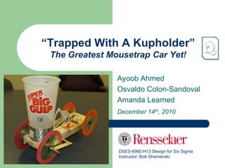
  • 1. “Trapped With A Kupholder” The Greatest Mousetrap Car Yet! Ayoob Ahmed Osvaldo Colon-Sandoval Amanda Learned December 14th, 2010 DSES-6960 H13 Design for Six Sigma Instructor: Bob Shemenski
  • 2. Agenda  Background of our vehicle concept  Why customers want this kit  Using CDOV process to enhance the car  Packaging & Assembly  Critical Parameters  Accuracy & Precision of the vehicle  Ease of use & Enjoying the beverage…
  • 3. Background: The Team  Ayoob Ahmed – Electrical Engineer in Non-Destructive Testing – Hoping to become a Lean/6 Black Belt to enhance test rig design & manufacturing – Loves optimizing for a challenge, especially one consisting of drink deliveries!  Amanda Learned – Mechanical Engineer in Aero/Thermo Part Durability – Learning to apply DFSS concepts for proactive durability KPC monitoring in her route to hold a Lean/6 Black Belt title – As a true P&W Engineer, loves to see a gear added into the mix!  Osvaldo Colon-Sandoval – Project Engineer in F119 Program - Exhaust System CIPT – Becoming a Lean/6 Black Belt to finally develop a logical & achievable scope, schedule, & cost for the company‟s most important engine program – Just happens to have an inner love for mousetrap powered vehicles!
  • 4. Background: The Mission  A frequent customer of DocFizzix tapped us on the shoulder, due to our love for mousetrap vehicles, optimization of drink delivery, and passion for creative solutions  With the challenge in hand, our team spent countless* hours to develop just the right new kit to be marketed through the company‟s website, hobby stores, & educational product distributors  Our sponsor desires to grow their market and is looking for a new product which customers, including students, teachers & hobbyists, can buy, build and use to compete in a new competition: “The Milk Run Challenge” * Actually not countless, please see actual schedule in the back-up slides
  • 5. Customers: Why This New Kit Will Sell They talked… Simple mechanics We listened… - No strings/tangles - A gear drive No more than a and followed through! - A screw-on break - Simple tools for build day to build, Interchangeable parts maybe even Something fairly - Customizable body just a few hours simple to put - Multiple wheel choices together, but at the use only simple - Repairable same time somewhat mechanics in Easy to use open ended. design… yet make - Breaking independent of it technically drivetrain I‟d like to challenge my interesting.. but - Reliable for multiple uses technical skills… must doable in a day… - Safe to operate be more than just put a Design “Built to win!” couple blocks together. - Delivers large beverages - Consistent & quick - Abides by ground rules
  • 6. CDOV: The Better Way to Design  Since we are Black Belts in training, the first step taken to develop the new kit was to decide on a process to follow: – Concept: linking our product to the market – Design: translating the VOX into creative prototypes – Optimize: Concentrating the design to meet design goals – Verify: Ensuring our product is buildable, reliable, & marketable  Our product has the customer in mind, with critical features optimized & verified in order for them to win “The Milk Run Challenge”  Our team strongly believes that keeping the definition of our „Customer‟ open from the start and following the CDOV process with this base, has really helped us to create an innovative product that will be marketable, even amongst the many other Doc Fizzix mousetrap powered vehicle options
  • 7. CDOV: How it Enhanced “Trapped With a Kupholder”  During the concept & design phases we generated some great creative ideas to meet the customer‟s need; however, we kept a back-up concept just in case the lead design was overcome by new failure modes; repetitive testing was done to ensure “the gear” would be user-friendly & reliable  At times, there may have been some “heated discussions” in regards to „what next?‟ OK, to verify, we need a GR&R with 3 users, 3 cars, and total distance No, we need the 3 cars, breaking, & wheels… … But “CDOV” pulled us together and kept us moving forward, which reduced R&D costs associated in the new kit & let us meet customer needs & desires Pull up our Critical Parameters to refer to, to answer this one!
  • 8. Project Plan: Actual hours spent on the project… Schedule Analysis for “Trapped With a Kupholder” Phase Schedule Actuals Variance Concept 36.5 31 5.5 Design 27 37 -10 Optimize 37 50 -13 Verify 47.5 46 1.5 180 Totals 148 164 -16 160 140 200 120 100 150 80 60 100 40 50 20 0 0 Concept Design Optimize Verify Totals Concept Design Optimize Verify CUM Schedule CUM Actuals Schedule Actuals
  • 9. Packaging & Assembly: Getting Started Items in your package Standard TWAK  57 individual pieces Kit contains 57 individual  A Manual for assembly & operation Pieces  Delivered in a priority mail small flat-rate shipping container Tools required for assembly  Wood glue & Super glue  2 adjustable clamps  Pliers  Wire cutters  A 5/8” drill bit  Ruler
  • 10. Packaging & Assembly: BOM, Part and “TWAK” Kit Cost Sale Price per kit @ $14.89 with a Profit Margin of 30% Description Size Location Qty Cost Total Cost Platform 3"x12"x.25" www.hobbylinc.com 1 $ 0.76 $ 0.76 Siderail 1.25"x12"x.25" www.hobbylinc.com 2 $ 0.65 $ 1.30 Front/Rear Axles 0.25" Brass www.hobbylinc.com 2 $ 0.39 $ 0.78 Metal Washers 4 x0.25"ID www.appliancepartspros.com 4 $ 0.10 $ 0.40 Chasis Plastic Washers 12x0.25"ID www.grainger.com 22 $ 0.04 $ 0.88 Mouse trap standard www.acehardware.com 1 $ 0.60 $ 0.60 Axle Gear Plastic www.SmallParts.com 1 $ 0.80 $ 0.80 Main Drivetrain Plastic www.SmallParts.com 1 $ 1.30 $ 1.30 Main Gear Brackets Plastic www.SmallParts.com 2 $ 0.25 $ 0.50 Drive Shaft 0.25"x 3" Brass www.hobbylinc.com 1 $ 0.39 $ 0.39 Drivetrain Gear Support Balsa 0.25" Square www.hobbylinc.com 1 $ 0.10 $ 0.10 Threaded Rod 1.25" of 8-32 Threaded Rod www.hardwareandtools.com 1 $ 0.05 $ 0.05 Wing nut 8-32 Wing Nut www.grainger.com 1 $ 0.40 $ 0.40 Balsa wood .125" x0.5"x3" www.hobbylinc.com 1 $ 0.10 $ 0.10 Braking System Balsa Rod 0.25" Rod www.hobbylinc.com 1 $ 0.02 $ 0.02 Cd's 6 Standard CD's www.meritline.com 6 $ 0.12 $ 0.72 Empty Roll of tape www.rhinomart.com 1 $ 0.87 $ 0.87 Rubber Gromet 0.25" to CD ID www.docfizzix.com 4 $ 0.30 $ 1.20 Wheels & Cupholders Balloons Assorted 6 www.amazon.com 4 $ 0.07 $ 0.28 Totals 57 $ 11.45 Sales Price per kit @ a Profit Margin of 30% $ 14.89
  • 11. Packaging & Assembly: Simple Steps for a Fun Project  This kit comes with clear, illustrated, step-by-step instructions for assembly and operation – Getting Started (1-3) – Building the frame (4-14) – Assembling the large gear (15-22) – Modifying the Mousetrap (23-29) – Fabricating the chassis (30-35) – Making Customizations (36) – Adding Wheels & a Cup Holder (37-46) – Affixing the break (47-52) – Using the Vehicle
  • 12. Packaging & Assembly: The Final Product  Drawing with critical features & dimensions – All critical features, like plastic gears and mouse trap, will be provided to the customer as part of the package. – Key assembly dimensions (drawing) will be provided to the customer on the assembly instructions to ensure proper performance of the car.
  • 13. Critical Parameters: Design Score Card Design score card documenting minimum of 3 system level Critical Parameters Critical Parameters Units LSL Target USL Mean Std Dev Cp Cpk Stop Distance (+/- 1 ft of desired distance) in -12 0 12 -0.61 2.13 1.87 1.78 Ultimate Distance (Able to move car min 16 ft.) ft 16 20 24 17.89 0.49 2.73 1.29 Straight Drive "Alignment" (+/- 1 ft after 16 ft.) in -12 0 12 2.97 5.79 1.18 0.97 Able to move 2 gal to dist of 16 ft in less than 30 min min 0 15 30 14.81 5.36 1.11 1.09 ˆ USL LSL Cp ˆ Min USL x , x LSL C pk 6ˆ 3ˆ 3ˆ
  • 14. Critical Parameters: Capability Growth Index (CGI) • A CGI completed to account for overall subsystems (braking, stop, distance, time) and target Cp = 2 • Cpi = min(Cp, 2) n 100 C p i CGI (%) i 1 n 2 CGI (%) = 100/4*((1.87/2)+(2/2)+(1.18/2)+(1.11/2)) CGI (%) = 77.0%
  • 15. Accuracy & Precision: Design Validation  Cpk‟s for the highest priority critical parameters, etc… – Optimized weight capability was set at… 32oz.  Distance traveled > 16ft… 18 ft.  Braking capability ± 12” … ± 2” from target.  Alignment capability ± 12”… ± 4” from axis.  Competition Time < 30min… 15 minutes.
  • 16. Accuracy & Precision: Validation of All Design Requirements Process Capability of Distance Traveled (using 95.0% confidence) Distance: LSL USL P rocess Data Within LS L 16 Ov erall Cpk of 1.29 Target * USL 24 S ample M ean 17.8906 P otential (Within) C apability Cp 2.73 Cp of 2.73 S ample N 16 Low er C L 1.77 S tDev (Within) 0.487589 U pper C L 3.70 S tDev (O v erall) 0.598392 C PL 1.29 C PU 4.18 Overall Performance: C pk 1.29 Low er C L 0.80 0.08% total population to U pper C L 1.78 O v erall C apability be out of Limits Pp 2.23 Low er CL 1.44 U pper CL 3.02 PPL 1.05 PPU 3.40 16.25 17.50 18.75 20.00 21.25 22.50 23.75 P pk 1.05 O bserv ed P erformance E xp. Within P erformance E xp. O v erall P erformance Low er CL 0.64 % < LS L 0.00 % < LS L 0.01 % < LS L 0.08 U pper CL 1.46 % > U S L 0.00 % > U S L 0.00 % > U S L 0.00 C pm * % Total 0.00 % Total 0.01 % Total 0.08 Low er CL *
  • 17. Accuracy & Precision: Validation of All Design Requirements Process Capability of Stop Distance (using 95.0% confidence) LSL USL Stopping : P rocess Data Within LS L -12 Ov erall Target USL * 12 P otential (Within) C apability Cpk of 1.78 Cp 1.87 S ample M ean -0.611111 S ample N 18 Low er C L 1.25 Cp of 1.87 S tDev (Within) 2.13809 U pper C L 2.49 S tDev (O v erall) 3.07052 C PL 1.78 C PU 1.97 C pk 1.78 Low er C L 1.16 Overall Performance: U pper C L 2.39 0.01% total population to O v erall C apability Pp 1.30 be out of Limits Low er CL 0.87 U pper CL 1.74 PPL 1.24 PPU 1.37 -12 -8 -4 0 4 8 12 P pk 1.24 O bserv ed P erformance E xp. Within P erformance E xp. O v erall P erformance Low er CL 0.79 % < LS L 0.00 % < LS L 0.00 % < LS L 0.01 U pper CL 1.68 % > U S L 0.00 % > U S L 0.00 % > U S L 0.00 C pm * % Total 0.00 % Total 0.00 % Total 0.01 Low er CL *
  • 18. Accuracy & Precision: Validation of All Design Requirements Process Capability of Alignment P rocess D ata LSL USL Within ALIGNMENT: LS L -12 Ov erall Target * USL S ample M ean 12 2.13889 P otential (Within) C apability Cp 1.18 CPK of 0.97 C P L 1.39 S ample N S tDev (Within) 18 3.38965 C P U 0.97 CP of 1.18 S tDev (O v erall) 3.35106 C pk 0.97 O v erall C apability Pp 1.19 PPL 1.41 Overall Performance: PPU 0.98 P pk 0.98 0.16% total population to C pm * be out of Limits -12 -8 -4 0 4 8 12 O bserv ed P erformance E xp. Within P erformance E xp. O v erall P erformance % < LS L 0.00 % < LS L 0.00 % < LS L 0.00 % > U S L 0.00 % > U S L 0.18 % > U S L 0.16 % Total 0.00 % Total 0.18 % Total 0.16
  • 19. Accuracy & Precision: Validation of All Design Requirements Process Capability of Time_Total (using 95.0% confidence) Time: LSL USL P rocess D ata Within LS L 0 Ov erall CPK of 1.09 Target * USL 30 S ample M ean 15.3467 P otential (Within) C apability Cp 1.11 CP of 1.11 S ample N 20 Low er C L 0.76 S tDev (Within) 4.49173 U pper C L 1.46 S tDev (O v erall) 5.24807 C PL 1.14 C PU 1.09 Overall Performance: C pk 1.09 Low er C L 0.71 0.43% total population to U pper C L 1.46 O v erall C apability be out of Limits Pp 0.95 Low er CL 0.65 U pper CL 1.25 PPL 0.97 PPU 0.93 0 5 10 15 20 25 30 P pk 0.93 O bserv ed P erformance E xp. Within P erformance E xp. O v erall P erformance Low er CL 0.60 % < LS L 0.00 % < LS L 0.03 % < LS L 0.17 U pper CL 1.26 % > U S L 0.00 % > U S L 0.06 % > U S L 0.26 C pm * % Total 0.00 % Total 0.09 % Total 0.43 Low er CL *
  • 20. Ease of Use: Operation & Delivery  In-person demo to be performed.
  • 21. Ease of Use: Customization  Deliver the beverage of your choice – Cup-holder fits all standard sizes – Steady enough to drive even with a Double Big Gulp! – Easily swap out cup-holder for “small glasses”  Wheels easily swap out – Add balloon-wrap Bushing simply – Add rubber band wrap pops off of axel & – Double-up the CD‟s out of CD center  Frame can be customized – Paint it with markers, crayons, pens, or paint – Add your logo! – Lengthen or shorten or make cut-outs in frame as desired
  • 22. Ease of Use: Enjoying the Beverages For just $14.89 + $4.95 S&H you too could be winning “The Milk Run Challenge”  Wow your friends & party guests!  Draw a crowd into your business $$  Let students have fun & learn at the same time …Then you can relax and enjoy the beverages too!
  • 23. Back-Up Slides GOOD BAD UGLY
  • 24. Phase 4 Requirements Action from Optimize Phase  Updated design score card including Transfer Functions, predicted Capabilities and Capability Growth Index (CGI) for minimum of 3 system level Critical Parameters Verify  Drawing with critical features and dimensions  Satisfaction of VOC, both customer and stakeholder needs  Validation of all design requirements generated in Concept phase  BOM and parts cost  Description of assembly, tools and process  Demonstrate operating procedure  Design Validation – Cpk for highest priority critical parameters  Updated Design score card Critical Parameters, Capability Growth Index (CGI)  Specific details: How DFSS tools and CDOV process influenced the development of your product design  Project Plan (actual hours spent on Concept, Design, Optimize and Verify phases)  Three working prototypes, materials and instructions for in-class competition.  Verify phase gate scorecard
  • 26. A Missing Anecdote from the Optimize Phase Report:  The Original Cup Holder was to carry 2 beverage containers, on either side of chassis  Market research was completed to determine standard cup holder sizes & requirements: 4.25” & 3.75” diameter should fit most all cups (except “Nalgene” bottle type)  As the design evolved, we were able to optimize the design by carrying more beverage in a single cup holder, in the center of the chassis  Testing & analysis showed small cups needed no further support than what the 4.75” standard cup-holder delivered: stability was consistent with repetitive testing  A cylinder provides simpler assembly than a 4- or 3-sided design, which requires multiple pieces and more locations for failure (FMEA) Design 1: Design 2a: Design 2b:
  • 27. Packaging & Assembly: The Final Product  Drawing with critical features & dimensions
  • 28. Packaging & Assembly: The Final Product  Drawing with critical features & dimensions
  • 29. Accuracy & Precision: Validation of All Design Requirements Process Capability Sixpack of Distance Traveled I Chart Capability Histogram LSL USL UCL=19.353 19 S pecifications Individual Value LS L 16 _ 18 X=17.891 U S L 24 17 LCL=16.428 1 3 5 7 9 11 13 15 16.25 17.50 18.75 20.00 21.25 22.50 23.75 Moving Range Chart Normal Prob Plot 2 A D: 0.855, P : 0.021 UCL=1.797 Moving Range 1 __ MR=0.55 0 LCL=0 1 3 5 7 9 11 13 15 16 18 20 Last 16 Observations Capability Plot 19 Within Within O v erall S tDev 0.487589 S tDev 0.598392 Values 18 Cp 2.73 Pp 2.23 O v erall C pk 1.29 P pk 1.05 17 C pm * S pecs 5 10 15 Observation
  • 30. Accuracy & Precision: Validation of All Design Requirements Process Capability Sixpack of Alignment_1_1 Xbar Chart Capability Histogram LSL USL UCL=9.19 S pecifications Sample Mean 6 _ _ LS L -12 X=2.14 U S L 12 0 LCL=-4.91 -6 1 2 3 4 5 6 7 8 9 -12 -8 -4 0 4 8 12 R Chart Normal Prob Plot UCL=12.25 A D: 0.328, P : 0.489 Sample Range 10 5 _ R=3.75 0 LCL=0 1 2 3 4 5 6 7 8 9 -10 0 10 Last 9 Subgroups Capability Plot Within Within O v erall 5 S tDev 3.32484 S tDev 3.35106 Values Cp 1.2 Pp 1.19 0 O v erall C pk 0.99 P pk 0.98 C pm * -5 S pecs 2 4 6 8 Sample
  • 31. Accuracy & Precision: Validation of All Design Requirements Process Capability Sixpack of Stop Distance Xbar Chart Capability Histogram 1 5 LSL USL UCL=4.35 S pecifications Sample Mean _ LS L -12 0 _ X=-0.61 U S L 12 -5 LCL=-5.57 1 2 3 4 5 6 7 8 9 -12 -8 -4 0 4 8 12 R Chart Normal Prob Plot UCL=8.613 A D: 0.781, P : 0.034 8 Sample Range 4 _ R=2.636 0 LCL=0 1 2 3 4 5 6 7 8 9 -10 0 10 Last 9 Subgroups Capability Plot Within Within O v erall 5 S tDev 2.33692 S tDev 3.07052 Values Cp 1.71 Pp 1.3 O v erall 0 C pk 1.62 P pk 1.24 C pm * -5 S pecs 2 4 6 8 Sample
  • 32. Accuracy & Precision: Validation of All Design Requirements Process Capability Sixpack of Time_Total I Chart Capability Histogram LSL USL 30 UCL=30.90 S pecifications Individual Value LS L 0 _ 15 X=14.81 U S L 30 0 LCL=-1.27 1 3 5 7 9 11 13 15 17 19 0 5 10 15 20 25 30 Moving Range Chart Normal Prob Plot 20 UCL=19.76 A D: 0.179, P : 0.905 Moving Range 10 __ MR=6.05 0 LCL=0 1 3 5 7 9 11 13 15 17 19 0 10 20 30 Last 20 Observations Capability Plot Within Within O v erall 20 S tD ev 5.3627 S tDev 6.03241 Values Cp 0.93 Pp 0.83 O v erall 10 C pk 0.92 P pk 0.82 C pm * 0 S pecs 5 10 15 20 Observation
  • 33. “Trapped With A Kupholder” Build Instructions Parts, Assembly, & Usage Manual for your new mousetrap powered vehicle* *Proprietary information of Ayoob Ahmed, Osvaldo Colon- Sandoval & Amanda Learned
  • 34. What is Standard TWAK Kit included in contains 57 individual your kit Pieces 2 chassis side rails (balsa wood sheet) 2 chassis spacers (balsa wood blocks) 1 large gear with spokes (plastic) 1 chassis platform (balsa wood sheet) 1 small gear (plastic) 4 reinforcing blocks (balsa wood rectangles) 1 bent metal tube 1 break arm (thin wood piece) 2 wheel axels (long metal tubes) 1 round wooden rod 1 gear axel (short square metal rod) 4 standard CDs 1 threaded rod (round metal) 2 balloons (std 8”, optional for assembly) 2 gear mounting feet (plastic) 1 cardboard flattened roll (packing tape 20 spacers (plastic disks) size) 4 bushings (rubber) 1 mousetrap (standard “Victoria” brand) 4 washers (optional for assembly) 1 wing nut
  • 35. Assembly steps 1-3: Getting Started 1. Lay out the entire contents of your kit 2. Check that all of the parts listed in the “What is Included in Your Kit” section are accounted for  If any parts are missing, please visit our website and submit a communication; please include your kit bar code and the name of the specific missing kit piece(s) 3. Gather the required equipment needed for assembly, not included in your kit: a. Wood glue b. 2 adjustable clamps c. Pliers d. Wire cutters e. A 5/8” drill bit f. Ruler g. Super glue h. Cup of your choice to carry liquid
  • 36. Steps 4-14: Building the Frame 4. Insert a wheel axel through one hole 9. Slide one end of the 2nd wheel axel of each chassis side rail through the hole at the other end of 5. Stand the side rails on their edges, as a chassis side rail shown and align short ends with a 10. When the inserted end is in the secure straight edge or T-square middle of the 2 side rails, slide the 6. Place a chassis spacer between the small gear onto this end of the axel two bars, up against the straight edge 11. Continue pushing axel through the and ensure it is not touching the axel last chassis side rail pre-drilled hole 7. Glue the chassis spacer ends to the 12. Push the small gear towards the inner side of each chassis side middle of the assembly, until the rail, with the wood glue back axel looks similar to that shown 8. Secure a clamp on the outer edges of in the picture the chassis side rails, aligned with the 13. Follow steps 5. through 8. again, for glued intersections this end of the assembly 14. Set Frame aside to let the wood glue 5. 12 dry . 8. 14 .
  • 37. Steps 15-22: Assembling the Large Gear 15. Slide the gear axel through a gear 19. Inject glue in-between the gear mounting foot, then 3spacer, then the axel and the hole of the mounting center hole of the large gear, then 2 foot, on both sides of the assembly more spacers, and finally the 2nd gear mounting foot, as shown in the 15 picture. This is the large gear . assembly. 20. Glue a reinforcing block adjacent to each flat outer edge of the mounting foot, such that the long side of each block aligns along the long edge of the chassis platform 16. Align the large gear assembly in the upper surface, as shown; ensure middle of the rectangular hole of the the inner edge of each block is chassis platform flush with the edge of the mounting foot 19 17. Place the foot adjacent to the outer “nub” of the gear‟s center hole, on the 21. Repeat step 18. to .secure the wide surface of the platform; and other mounting foot place the opposite foot on the thinner surface of the platform, as shown 16 18. With the large gear assembly aligned . 17 centered in the platform‟s cutout, & . glue the flat surface of each mounting 22. Set chassis platform assembly foot to the surface of the chassis aside to let the wood glue dry platform
  • 38. Steps 23-29: Modifying the Mousetrap 23. Using pliers, remove the mousetrap‟s 26. Place the mousetrap on the locking bar top of the chassis 24. Using wire Cutters, cut the platform, adjacent to the lever/snapper arm of the standard mounting foot for the large mousetrap at the location marked in gear, on the wider side of green on the mousetrap the platform, as shown; supplied, approximately ½ across the ensure the lever arm is horizontal portion pointing to the shorter end of the chasses 25. Using pliers, bend the remaining arm 23 length ~90-degrees, toward the . outside, as shown 27. Align the center of the 25 spring on the . mousetrap, with the center of rotation for the large gear; as such, the bent arm 24 length should now be . almost (but just shy of) touching the gear‟s surface; mark the front & back of the mousetrap 28. Once the location is defined, glue the bottom of the mousetrap to the top of the chassis platform; remember to use plenty of glue! 29. Insert the bent metal tube
  • 39. Steps 30-35: Fabricating the Chassis 30. Once the glue on the frame and 33. Place glue on the outer edges of large gear assembly on the chassis the chassis platform then re-align platform are dry, place the assembly in-between the side rails, using platform between the 2 chasses side the marks from step 32; slight rails; ensure the large gear and small forward/aft shifts may be made to gear are at the same ends of the ensure a good chasses 34. Secure a clamp on the outer 31. Shift the platform forward and aft, edges of the chassis side until the teeth of the two gears meet; rails, towards the front of the the small gear may have to be shifted platform & then secure a second along the wheel axel clamp towards the rear 32. Once the assembly is placed such 35. Set chassis assembly aside to let that the teeth of the two gears 33 the wood glue dry intersect and are able to rotate and . 31 catch on each other, mark the . location of the front & back edges of the chassis platform on the side rails; 4 marks should be made it total 32 . 35 .
  • 40. Step 36: Making Customizations  Balloons are provided, if it is  Washers are provided, these may desirable to have additional friction be used to reduce friction between on your wheels – and if you want to your axel and the chassis add some fun color  Super-glue the washer to the  Slice the balloon such that just the outside edge of the chassis middle is left, creating a thick rail, such that the axel hole in the rubber-band shape wood is visible through the washer  Force balloon band around the  the use of washers will minimize outside lip of the CDs the contact surfaces – and they  These may be added to none, give your car a nice finished look some, or all wheels; or you may  Another suggested alternative (not even put multiple CDs underneath included) is adding ball bearings to the balloon wraps really minimize any losses due to wheel friction  Another easy suggestion for  And of course, Don‟t forget your customization is to wrap the cup license plate! holder with ribbon or any light- weight decorative material of your choice
  • 41. Steps 37-46: Adding Wheels & Cup Holder 37. Insert a rubber grommet into the 42. Once the large gear is centered on center of each of the 4 CDs the small one and there is enough 38. On the wheel axel away from the room on either edge for the gears, insert a few spacers onto the wheels, glue the small gear to the end of the axel and then “cap” it by rear axel pushing the axel end through the now rubber center of the CD 43. Take the flattened cardboard strip 39. Repeat step 38, using the opposite and curl it into a loop, such that it end of the same axel; this is now the once again looks like the center of front wheel assembly 39 . a tape roll 44. Apply glue along the seem adjoining the two ends of the loop; this is now your cup holder 45. Place the cup holder on the top surface of the chassis platform, in 40. Attach the last two wheels to the 2nd the middle of the front wheel wheel axel to form the rear wheel assembly assembly in a similar manner as the front wheel assembly 46. Ensure the cup holder edges are not in contact with any moving 41. Once the rear wheels are attached parts of the vehicle and then 41 to it, the wheel axel or the small gear . secure the cup holder on the 40 in the middle of it, may need to be . chassis with glue along the bottom shifted; spacers may need to be edge added/removed to either side to adjust
  • 42. Steps 47-52: Affixing the Break 47. Using pliers, Insert the threaded 50. Insert the round wooden rod into rod into the end of the hollow axel this whole and glue at the seem in the front wheel assembly, on between the rod and the chassis 50 the side of the vehicle opposite of . the large gear side; turn and tap in to ensure a tight fit 48. Next, measure 3 inches from the threaded rod (or the center of the CD), in the direction of the rear 51. Glue one wing of the wing nut wheel assembly and make a onto “the break” (the small thin mark; keep it at approximately strip of wood provided) and let the same vertical height as the dry axel 47 . 52. Once the wooden rod and strip are stuck in place, the wing nut can be screwed onto the threaded rod sticking out of the 49. Using the drill bit, manually turn front axel; note when spun, the the bit by hand into the soft balsa 49 52 rod should come into contact with wood at the marked location, until. the break . a whole is made through the side rail
  • 43. Using the Vehicle  Once all of the assembly steps have been followed and all glued joints are dry (we recommend over-night), your new mousetrap powered vehicle is ready to be tested out Drive Spin wheel Release train forward to gear to see starting engage it zoom location spring forward To set the break up, tighten the wing nut Feel free to by spinning the wheel, until the break engages, then untwist the wing nut and deliver the count the number of turns the CD makes beverage of Translate the # of turns into feet of travel your choice, up with our translation sheet provided to 44oz
  • 44. Reference Sheet # Turns 0.8 1.6 2.4 3.2 4.0 4.9 5.7 6.5 7.3 8.1 8.9 9.7 10.5 11.3 12.1 12.9 Dist (ft) 1 2 3 4 5 6 7 8 9 10 11 12 13 14 15 16 Use 32 Oz for 16‟ Runs For 12‟ or Shorter Runs use 40 Oz The Good: •¼ Turn for 11‟ Empty •1/3 Turn for 16‟ Empty •2nd Spoke for 11‟ Loaded •¼ Turn for 6‟ Loaded The Bad: •Start Bad with offset of 1‟ to the left for 16‟ •2nd Spoke for 11‟ Empty The Bad & The Ugly: •Need Full power when Loaded

Editor's Notes

  1. Interviews were conducted with school teachers &amp; STEM enthusiasts, young adults &amp; bar owners/patrons, tech enthusiasts/hobbyists &amp; innovators, and recruiters &amp; HR personnelThe results were organized in a KJ analysis and then a Kano analysisThe translated VOX results were then translated further into system requirements via a HOQ, then into design requirements via a 2nd HOQ, and finally into process requirements via a 3rd level HOQThe requirements also lead us to define the critical to quality parameters once the P-diagrams and DFMEAs were created and revised through the process
  2. Another example was the Cup Holder designing steps taken:“why are we spending time on this when we don’t know if this is a critical parameter to the design?”“Oh yah, let’s start with the VOX analysis and see where it takes us…”“OK, we need a cupholder, let’s see all the dimensions, types, etc. are available (market research ensued) and build are car with enough space to hold a design like this”“Well, we know the dimensions, but how tall, strong, etc does it need to be…?”“Let’s do some trial runs in our DOE to check stability”… “hey look! Stability is not an issue within our design space!”We then concluded it’s critical to have one, but as long as it fits standard sizes &amp; doesn’t fall off, that’s all that matters for the customer.Yet another example is using the FMEA to mitigate an assembly failure mode:The force that the gear applies to the surface of the chassis, as it tries to move in the direction that the mousetrap spring is pushing it (a rotational force) was found to create a potential failure mode – the gear mounts releasing from the surfaceThe effect would be the glue not being strong enough to oppose these forces and the drive train releasing &amp; not producing the forward car motion as plannedThe analysis led us to add reinforcing beams on either side of the large gear mounting feet. This relieves the sheer forces on the surface of the chassis and reinforces the adhesion between the large gear and the chassis, while not adding much weight.
  3. Identified Schedule RisksThe scheduled and actual hours for the project are show in the table below. The total allowable hours have increased to 164 hours, up by 16 hours from the original estimate of 148 hours. The team experienced a total “cost” variance of (-16) hours at the end of the Verify Phase. During the Design and early in the Optimize Phase, the team was carrying two parallel designs, the geared as the primary and the basic lever arm design as the backup. The negative “cost” variance at those two faces was due to the added work/complexity of having two different concepts, being design and briefly optimized at the same time. Due to the success of the “the geared design” the lever arm design was drop at the optimization phase and the car was modified to become another test vehicle. Early in the project, the team decided to take the risk and put more time in the design and optimize phase, because we found those two phases critical for the success of the design and competition. The team found really useful to have both designs, which are completely different, compete to each other and have a clear idea the path to follow after that point. Also, above is the cumulative “cost” variance by phase, to give us a pictorial perspective on how we did relative to the use of the allocated hours.
  4. 57 kit pieces consist of the following:2 chassis side rails (balsa wood sheet)2 chassis spacers (balsa wood blocks)1 chassis platform (balsa wood sheet)4 reinforcing blocks (balsa wood rectangles)1 break arm (thin wood piece)1 round wooden rod4 standard CDs2 balloons (std 8”, optional for assembly)1 cardboard roll (std packing tape size)1 mousetrap (standard “Victoria” brand)1 large gear with spokes (plastic)1 small gear (plastic)1 bent metal tube2 wheel axels (long metal tubes)1 gear axel (short square metal rod)1 threaded rod (round metal)2 gear mounting feet (plastic)20 plastic spacers4 rubber bushings1 wing nut4 washers (optional for assembly)
  5. Just adding a little business to this mix… with a Profit Margin of 30% on each car, $ 3.44 per unit. If we apply a Engineering Hourly Rate of $15, we are “cheap” engineers, and combine it with the 164 hours that were put on this project. The Non-Recurring Engineering charges sum up t ~$2400. A total of 700 “TWAK” Car kits need to be sold to at least break even on this project.
  6. See TWAK Powerpoint#2 with full instructions for assembly
  7. Bigger size “drawings” are available in the backup slides…
  8. In order to win the Milk Run Challenge… our design team established the (4) Critical Parameters above. The team, at the beginning, was very concern about the stopping and alignment capability of the car, and therefore we cut the customers requirements (4’ by 4’) into half for our requirements. By doing that, the team felt very confident that we were creating a robust design.Our approach was to came up with a geared design to transfer biggest amount of energy possible form the Mouse Trap spring. After several optimization loops in the “ugly” test car, the team decide to set an standard weight of 32 oz to reach the 16ft very confidently. After setting the weight at 32oz, at the start of the verify phase by conducting several capability analysis trials to ensure that we were going to meet all the customer requirements.
  9. Although there is room for improvement for a CGI of 77%, the team feel very pleased by the results, because the simple fact that our distance, stopping and alignment design critical parameters are much tighter than the “Milk Run Competition” requirements.
  10.  The highest priority requirements for the “TWAK” mousetrap powered car design were the distance traveled and the ability to stop at that distance. During the optimization/verification phase, we optimized the amount of weight that we can carry (which is 32 oz) and still feel very confident of move the water and achieve a minimum distance of 16 feet. Having that demonstrated with a Cpk value of 1.78, then we moved to optimize the ability to stop the car within +/- 1 foot of the target distance. Which is really difficult because the distance to be traveled is unknown until the day of the competition, but we feel very confident with a Cpk value of 1.29, that we are going to be able to stop the car within the 2 feet by 2 feet square. Another parameter that we underestimated from the beginning the car alignment, also known as the ability to reach the distance of 16 feet and be +/- 1 foot to the left/right of the starting axis, were demonstrated in the Design Score Card and achieving Cpk of 0.97.Then we turned our attention to our competition (we really do not foresee any difficulty to beat them on Tuesday night, but it is ok to call them “the competition”). With “the competition” stating that their test car can carry about ten pounds on their optimization presentation, which we don’t believe until we see it, we decided that our secondary weapon available to win this race is the ability to be quicker than them in the competition. We consider that our cars are much easier to setup, because we are not dealing with pulleys or strings, and the gear power train is more like aim and shoot. So, if we are moving 32oz on each trip, we need to make sure that we complete our 8 trips (move 2 gals) in half of the allowable time which is thirty minutes. Several trial runs were conducted, and definitively, we demonstrated that we were able to move the 2 gallons in 15 minutes with a Cpk value of 1.09. While validating the “final” design, we found that one of the most influential factors for the overall variation was the operator. So, we took extra time to proper train all the operators and ensure the car was properly set in a quickly manner.
  11. What does your process capabilty for time tell you about the probabiltiy of finishing in less than 30 minutes?
  12. By this chart, we can say that the probability for the “TWAK” team to complete the Milk Run Challenge in less than 30 minutes is 99.74%.
  13. In-person demo to be performed by Ayoob
  14. What does your process capabilty for time tell you about the probabiltiy of finishing in less than 30 minutes?
  15. What does your process capabilty for time tell you about the probabiltiy of finishing in less than 30 minutes?
  16. What does your process capabilty for time tell you about the probabiltiy of finishing in less than 30 minutes?
  17. What does your process capabilty for time tell you about the probabiltiy of finishing in less than 30 minutes?