1. Issue 2.0 3-1
Proprietary and Confidential
Not for disclosure outside of Pacific Telesis and Lucent Technologies as stated in
G.P.A. No. A00567 Sections II.14 and II.15 Except Under Written Agreement
ASOS Release 2: Hardware
Architecture 3
Craig Reading
Director of Architecture
Room 4W-U06
184 Liberty Corner Road
Warren, NJ, 07059
908-580-6817
attmail!careading
David A. Wandelt
Hardware Architect
Room 4W-U06
184 Liberty Corner Road
Warren, NJ, 07059
908-580-6062
attmail!dwandelt
File Name: ARCHHW_FM7.FM
Document ID = asos:r1:arch:hw
Template Version = 1.6
The following information identifies where this file exists within SABLIME:
Generic: pbfe2.0
Relative Path: arch/
2. ASOS Release 2: Hardware Architecture
3-2
Proprietary and Confidential
Not for disclosure outside of Pacific Telesis and Lucent Technologies as stated in
G.P.A. No. A00567 Sections II.14 and II.15 Except Under Written Agreement
Document History Table 3
The history of this document is contained in the following table. Each version of
this document is identified by the version number, document state, date, and
author(s). The document state can be one of the following:
■ DR - DRAFT
■ DFR - DRAFT FOR REVIEW
■ RFW - READY FOR WALK THROUGH
■ SO - SIGNED OFF
■ MR - BASELINED DOCUMENT WITH MR CHANGES INCORPORATED.
Table 3-1. Document History
ISSUE
NO. DSI DATE AUTHOR(S) DESCRIPTION
2.0 MR 3/1/96 Colby fe960440: move to pbfe2.0
2.0.0a MR 4/19/96 Wandelt fe960675: Sun workstation info
2.0.0b MR 7/29/96 Wandelt fe96819: update for 2.0; networking;
NFS server; implementation stages
timing and locations.
2.0.0c MR 9/4/96 Wandelt fe960699: DB disk capacity growth.
2.0.0d MR 9/26/96 Wandelt fe961331: Add info for hardware path
from datacenter to HDTs.
2.0.1 MR 10/17/96 Reading Revisit security tier info to incorporate
current understanding.
Executive Summary 3
The ASOS Hardware Architecture is intended to provide the highest level of fault
resistance without having to meet total “Fault Tolerant” criteria, which would
substantially increase implementation complexity and cost. Although in many
respects the architecture resembles a fault-tolerant environment, it allows for
platform and application growth beyond what is currently possible with today’s
fault-tolerant products. The ASOS hardware system is intended to track customer
growth demands and provide a cost-effective and operationally-efficient means of
handling forecasted loads and managing system resources during unexpected
natural disasters. In short, the system is designed to allow for hardware
3. ASOS Release 2: Hardware Architecture
3-3
Proprietary and Confidential
Not for disclosure outside of Pacific Telesis and Lucent Technologies as stated in
G.P.A. No. A00567 Sections II.14 and II.15 Except Under Written Agreement
component, subsystem, system, network, or data center outages, for either
normally-scheduled maintenance or unexpected natural disasters, by preventing
any single point of failure from making any functional subsystem unavailable.
Introduction 3
This document primarily describes the ASOS hardware architecture designed by
Lucent Technologies for Pacific Bell (P*B).
ASOS hardware will be implemented in stages, ultimately consisting of four
physical data centers, with two data centers at each of two regional sites. See
“Stage Content” on page 3-5 for details.
NOTE:
The hardware architecture outlined in this document is subject to fine-
tuning to accommodate changes in hardware, network, system, or sub-
system componentry. Such changes will be based on actual system
performance tests while following the system and customer requirements
specified in the “ASOS Tier 4 Functional Requirements.”
Vendors’ hardware and software components are mentioned herein to provide
clarity and completeness; details on those items may be obtained from their own
documentation.
What is Required of the Hardware Architecture? 3
This hardware architecture meets the following requirements:
■ It supports the ASOS software architecture.
This assumes applications running on large servers with users seated at
Unix-standard workstations or IBM-standard PCs (depending on the
specific application.) Servers used meet ASOS’s application coresidency
requirements (i.e., several applications may reside on one application
server.)
ASOS application coresidency and the number of application processors
(SPUs) may change through the software architecture, design and test
cycles and perhaps even after deployment.
■ It provides “24-by-7” service.
This is defined as rare and short outages, with no scheduled daily or
weekly downtime. Some monthly downtime for scheduled maintenance is
required. (Availability criteria are defined in the performance section of
“ASOS Tier 4 Functional Requirements.”) ASOS’s “high availability” design
4. ASOS Release 2: Hardware Architecture
3-4
Proprietary and Confidential
Not for disclosure outside of Pacific Telesis and Lucent Technologies as stated in
G.P.A. No. A00567 Sections II.14 and II.15 Except Under Written Agreement
provides for duplication of critical computing and networking components.
“High Availability” on page 3-9 covers this topic.
■ It will survive a localized natural disaster.
ASOS hardware is distributed over a wide geographic area to ensure
uninterrupted service in the event of a localized natural disaster. This
requires a suitable wide area network (WAN) from Stage Three forward,
when either ASOS site will be able to provide service to the entire P*B
territory. See “Network Architecture” on page 3-20 about the WAN.
■ It supports TCP/IP.
Since the current network in use by P*B is based on TCP/IP, ASOS will fit
within this framework.
■ It meets the specified performance criteria.
ASOS hardware has been chosen to meet performance criteria (see ASOS
Release 1: Performance Budgets).
Constraints on Choice of Hardware 3
■ P*B has specified Hewlett-Packard (HP) as its vendor of choice for servers.
■ P*B Unix workstations will be based on both HP and SUN platforms.
■ P*B’s vendor of choice for routers is Cisco.
■ P*B’s vendor of choice for hubs is Cabletron.
If the needs of the project cannot be met with equipment from the vendors listed
above, Lucent Technologies may request a variance from P*B to use other
vendors.
Geographical Considerations 3
To understand the hardware used in ASOS, it is useful to describe the
geographical arrangement that will exist at P*B.
Large application and database servers will be located in the four data centers
noted above in “Phased Implementation”.
Most workstation and PC users (primarily Customer Care personnel) will work at
megacenters. The final number of these centers is not yet settled; four is the
current estimate.
There will also be at least one Case Worker Bureau (CWB) site, at which there
will be OA&M administrators using Unix workstations and IBM-standard PCs. The
disaster plan for the CWB site is being actively investigated.
5. ASOS Release 2: Hardware Architecture
3-5
Proprietary and Confidential
Not for disclosure outside of Pacific Telesis and Lucent Technologies as stated in
G.P.A. No. A00567 Sections II.14 and II.15 Except Under Written Agreement
There will also be a VIP Service Center, with some ASOS users. The meaning
and implications of this remain under investigation.
Connectivity across multiple ASOS user sites and data centers at geographically-
distant locations requires a wide area network (WAN). Lucent Technologies will
provide network requirements to P*B, but P*B will design, implement and manage
the WAN.
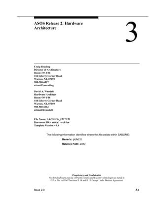
Phased Implementation 3
ASOS hardware is to be implemented in four functional phases, or “stages.” This
section describes the timing and content of each stage.
Stage Content 3
Figure 3-1 pictures ASOS deployment stages.
Table 3-2 lists each deployment stage and the sectors served when that stage is
complete
Table 3-2. Sectors Served, by Stage and Data Center
Stage Data Center Sectors Served
One North 1 North
Two South 1 South
Three North 2 North and South, backup
Four South 2 North and South, backup
.
The sections below describe the contents of each deployment stage.
Stage One 3
Hardware Implementation Stage One, completed in December of 1995,
established ASOS’s first production data center. This first of the two north-region
data centers (“North 1”) consists of one pair of database server SPUs sharing a
RAID disk farm (see “Database Servers Design” on page 3-36), and one
complement of application servers (detailed in “Application Servers Design” on
page 3-33). It is completely operational in all respects, including data mirroring
and the other high-availability features noted in this document, except for those
requiring the other ASOS data centers, such as cross-center database shadowing
(page 3-37) and severe localized earthquake protection.
6. Note: beginning with Stage Two, application servers may run HP-UX 10.x. If so, North 1
would be retrofitted with 10.x and MC/ServiceGuard at that time.
Figure 3-1. Phased Implementation Stage Contents
T500
#2
560 GB RAID
disk farm
Application
Servers
FDDI
#1
Database
Servers
10.x
HP-UX
North 1
Stage One: December, 1995
9.0x
HP-UX
#1FDDI
Active
T500
#2
Active
TT500
#1 #2 #3 #4 #5
ATM hubs/switches
9000
#2
Application
Servers
FDDI
#1
Database
Servers
10.x
HP-UX
10.x
HP-UX
Active
9000
#2
Active
ATM hubs/switches
OC3 or DS3
South 2
9000
#1
9000
#2
9000
#3
9000
#4
9000
#5
T500
#2
Application
Servers
FDDI
#1
Database
Servers
10.x
HP-UX
North 2
10.x
HP-UX
Active
T500
#2
Active
ATM hubs/switches
OC3 or DS3
9000
#2
Application
Servers
FDDI
#1
Database
Servers
10.x
HP-UX
South 1
10.x
HP-UX
#1FDDI
Active
9000
#2
Active
9000
#1
ATM hubs/switches
9000
#2
9000
#3
9000
#4
9000
#5
Pacific Bell
WAN
External to
Data Centers
500+ workstations total
~20 workstations/LAN segment
Stage Two: 1Q, 1998
Stage Three Stage Four
AS AS AS AS AS
9000
#1
9000
#2
9000
#3
9000
#4
9000
#5
560 GB RAID
disk farm
T T T TT500 T500 T500 T500
#1FDDI
#1FDDI
560 GB RAID
disk farm
560 GB RAID
disk farm
ASOS Release 2: Hardware Architecture
3-6
Proprietary and Confidential
Not for disclosure outside of Pacific Telesis and Lucent Technologies as stated in
G.P.A. No. A00567 Sections II.14 and II.15 Except Under Written Agreement
Note that the “hubs/switches” shown in the North 1 data center in Figure 3-1 are
not installed until Stage Two, since before that time there is no other data center
for North 1 to communicate with.
NOTE:
The size of the disk farm shown for the database servers in
Figure 3-1 provides adequate storage through ASOS Release 2.0.
Actual disk farm sizing for Stages Two, Three and Four may change
based on the software release current when each stage is deployed.
7. ASOS Release 2: Hardware Architecture
3-7
Proprietary and Confidential
Not for disclosure outside of Pacific Telesis and Lucent Technologies as stated in
G.P.A. No. A00567 Sections II.14 and II.15 Except Under Written Agreement
Stage Two 3
At the completion of Stage Two, a first south-region data center (“South 1”) will be
operational at the Fairfield site. North 1 and South 1 database servers will be
linked (using the best technology available at deployment time; possibly ATM),
facilitating database shadowing across sites; see “Database Shadowing” on
page 3-37 for details. The current working view is for this work to be completed
when the number of cut-over customers exceeds approximately 500,000.
The exact processor hardware used in South 1will depend on the technology
available when it is deployed, since the number of SPUs required will depend on
whether HP-UX 10.x can be run on them.1
If it can, MC/ServiceGuard, which
supports active-active pairing, will be used in place of the SwitchOver/UX
supported by HP-UX 9.0x, and either some form of asymmetrical “n+1 sparing” or
cross-site failover coverage will be used; the exact technology will again depend
on what is available at deployment time.
Stage Two is also projected to upgrade North 1’s application processors to
HP-UX 10.x if the asset applications will run under it by then. This change would
enable redefining the roles of the application processors to Active-Active status
from the Active-Standby roles given them in Stage One. If this happens, North 1’s
standby T500s may then be reassigned other roles.
Stage Three 3
With the implementation of ASOS Stage Three, the second north-region data
center (“North 2”) will be operational in Fairfield. North 2 will shadow the north and
south site databases (i.e., all north and south sector active customers). Should
Fairfield fail, North 1 will assume all of Fairfield’s functionality seamlessly and
continue to meet performance requirements. Because of the active/standby
nature of the relationship between the two sites, this backup data center will not
add capacity or performance to ASOS; it is added as a safeguard, contributing to
the system’s overall “high availability” and disaster recovery capabilities.
Stage Four 3
With the deployment of ASOS Stage Four, the final data center (“South 2”) will be
brought up.
South 2’s data will be shadowed in North 1. North 2’s data will be shadowed in
South 1. This additional growth of the south center is solely for full “high
availability” and disaster recovery coverage for the Fairfield north site.
1 HP-UX 10.x being run on the application servers will itself depend on whether the ASOS
assets have been ported to HP-UX 10.x by deployment time.
8. ASOS Release 2: Hardware Architecture
3-8
Proprietary and Confidential
Not for disclosure outside of Pacific Telesis and Lucent Technologies as stated in
G.P.A. No. A00567 Sections II.14 and II.15 Except Under Written Agreement
Stage Timing 3
The four implementation stages of ASOS hardware will take place over several
years. This way, growth can be subscriber demand- and community growth-
driven, allowing equipment purchases to be deferred to meet that growth.
Figure 3-2 shows the projected growth and its relationship to ASOS
implementation stage timing
Figure 3-2. Phased Implementation Timing Dependencies
Stage 4
North
South
Total Time
On Line
Living Units
250 K
Stage 1
Stage 2
1.0 M
Stage 3
(12/95)
(~1Q/98)
>2000
2.0 M
3.0 M
4.0 M
5.0 M
500 K
3.75 M
1.25 M
5 M
.
Stage One became available for bringing up northern California customers in
December, 1995.
Stage Two will be brought up when the number of customers passes ~500K,
probably not sooner than the first quarter of 1998.
Stage Three deployment will begin as soon as the total number of living units
actually on line passes approximately one million.
According to current projections, the south region will provide roughly three times
as many customers as the north region. Based on this, the machine processing
north-region activity will be handling 250,000 customers, while the machine
9. ASOS Release 2: Hardware Architecture
3-9
Proprietary and Confidential
Not for disclosure outside of Pacific Telesis and Lucent Technologies as stated in
G.P.A. No. A00567 Sections II.14 and II.15 Except Under Written Agreement
processing south-region activity will be handling 750,000 customers, at Stage
Three deployment time.
Stage Four will be implemented at some point after Stage Three that is yet to be
determined, based on subscriber demand growth and high availability
requirements current at that time.
High Availability 3
The ASOS hardware architecture design implements “high availability”
configurations.
High-availability systems provide greater protection against down time than
standard systems, at a lower price than true “fault tolerant” systems. Decisions
bearing upon both the server and network configurations chosen for ASOS also
have been made consistent with these availability constraints.
Each server uses two processor boxes, mirrored disks on independent disk
controllers, and duplicated connections to the ASOS LANs. Each site has enough
disk storage to hold not only its own data, but that of the other site also. During
failed-over operation, ASOS would run in degraded mode (because of being
without standby processors), since the standby servers would be used as primary
servers for the out-of-service site. Network capacities have been engineered for
serving north and south sectors simultaneously from a single site.
Each server draws mains power from two separate uninterruptible power supplies
(UPSes). See “Use of Dual UPSes for Servers” on page 3-12 for details.
ASOS LAN components make use of replicated hubs and routers. LAN
componentry and configuration are detailed in “Network Architecture” on
page 3-20.
Workstation-level LANs (each user site may have several, and there will be many
user sites) will not use replicated components, since failure of a workstation LAN,
or of any of the workstations in it will affect only a small subset of the users, who
will generally be able to find other workstations.
Failure and Repair Considerations for the Servers 3
A high-availability architecture analysis must consider individual component
failure, and detail the effects on system operation of each failure and its repair.
10. ASOS Release 2: Hardware Architecture
3-10
Proprietary and Confidential
Not for disclosure outside of Pacific Telesis and Lucent Technologies as stated in
G.P.A. No. A00567 Sections II.14 and II.15 Except Under Written Agreement
NOTE:
The items below assume the failover features provided by HP in their
servers, using either their SwitchOver/UX (application servers) or
MC/ServiceGuard (database servers), and MirrorDisk/UX software.
Failed Server (processor, memory or major I/O
component) 3
The failure of a standby processor will have no impact on users, but it will be
detected and the maintenance community notified.
A failed processor box in a duplex configuration can be powered off for repair
without affecting the other processor box.
The standby processor in each duplex-configured server will notice the failure of
its mated active processor through heartbeat monitoring. The two general classes
of servers in ASOS, database servers and application servers, run different
versions of HP-UX and failover software, with the following implications:
Application servers 3
Running HP-UX version 9.0x, ASOS application servers use HP’s SwitchOver/UX
to transfer control from a failed processor to its mated standby. During switchover,
the software performs the actions noted below, interrupting service for several
minutes while transferring control to the active processor. When switchover is
completed, the former standby processor becomes the active processor. The
failed mirror processor, when returned to service, becomes the standby
processor.
The time elapsed until the system is again operational has the following
components:
■ Processor hardware checks, proportional to the amount of memory, and
potentially several minutes. It may be possible to turn this function off.
■ Rebooting, including a check and repair of UNIX file systems. Total time
here depends on the size of the file systems and the degree of corruption,
and can vary from a minute to the better part of an hour.
■ Application start-up, which varies according to the application(s) running
on that particular processor. Some ASOS applications may require time-
consuming establishment of connections to many network elements.
Database servers 3
Running HP-UX version 10.1, the database servers will use HP’s
MC/ServiceGuard to transfer the failed processor’s file serving responsibilities to
its active mate.
11. ASOS Release 2: Hardware Architecture
3-11
Proprietary and Confidential
Not for disclosure outside of Pacific Telesis and Lucent Technologies as stated in
G.P.A. No. A00567 Sections II.14 and II.15 Except Under Written Agreement
MC/ServiceGuard transfers control much more quickly than the SwitchOver/UX
software used on the application servers, and will interrupt service only briefly (a
few minutes). The speed increase is accomplished by a combination of not
needing to reboot, and by eliminating some of the checks that SwitchOver/UX
performs both before and during the reboot process. It does, however, still need to
start up applications that were running on the failed processor.
Failed disk drive 3
The database servers use RAID technology disk systems to enhance perfor-
mance through data “striping.” This type of RAID disk management is called
“level 0.” Level 0 RAID does not duplicate data, as would RAID level 5 for exam-
ple, but does improve performance by spreading a file’s contents across multiple
disk spindles. Level 0 RAID also maximizes the utilization of physical disk. Both
application and database servers run MirrorDisk/UX to ensure maximum availabil-
ity and minimum downtime.
When a failed disk is replaced, MirrorDisk/UX recreates on the replacement drive
the functionality of the failed drive. Although this happens transparently to
applications, significant disk activity is required for a long period of time, perhaps
a good fraction of an hour, producing some disk subsystem performance
degradation until it finishes.
Failed Disk Controller 3
To eliminate the failure of a disk controller (HP calls it a “host adapter”) as a single
point of failure, database and application processors are equipped with redundant
SCSI host adapters and O/S-level disk mirroring. A processor detecting a failed
SCSI host adapter notifies maintenance personnel of the failure. Application
servers and database servers use differing disk technologies, and hence different
availability-enhancement models, as described in the following subsections.
Application Servers 3
The two SPUs in each application server pair share common JBOD SCSI disk
storage both for O/S and application software. Each string of JBOD disk drives on
a single SCSI bus is connected to both Switchover-paired SPUs by a single FWD
SCSI host adapter in each SPU. Each host adapter terminates one end of the
SCSI bus. If the host adapter on the Active SPU fails, a failover to its associated
standby is initiated. A host adapter failure on the Standby SPU is detected the
next time the system requires I/O activity from it, and the system notifies
maintenance personnel of the failure then.
Database Servers 3
The database servers use two types of disk: JBOD and RAID disk arraying. If one
of the host adapters for JBOD disks (used for MC/ServiceGuard lock disk and for
“2nd boot mirroring”) fails, the system detects it on the next I/O request, and
12. ASOS Release 2: Hardware Architecture
3-12
Proprietary and Confidential
Not for disclosure outside of Pacific Telesis and Lucent Technologies as stated in
G.P.A. No. A00567 Sections II.14 and II.15 Except Under Written Agreement
notifies maintenance personnel. Since both SPUs in a ServiceGuard pair are
actively processing during normal operation, detection of a failed host adapter
happens virtually the instant the adapter fails.
The RAID disk arrays used on the database servers are connected to their
associated SPUs through either one (operating system) or two (Oracle database)
FWD SCSI host adapter cards.
The operating system disk arrays are not connected to both SPUs in the
MC/ServiceGuard pair. If the host adapter card for the primary operating system
array fails, the system switches to the operating system mirror disk array, and the
operator is notified.
The database disk arrays are connected to both of the paired database SPUs.
Each database disk array is equipped with two storage processors for both
redundancy and enhanced performance. If only one of the
Failed network adapter 3
ASOS network adapters are Dual-Attached Station (DAS) configured to minimize
the impact of a network adapter failure. Each server’s adapter is “dual-homed,”
i.e., it is connected to two separate hubs through two separate interfaces on a
single network adapter card.
In the event of a complete failure of a processor’s network adapter card, a failover
is initiated, and maintenance personnel are notified.
Use of Dual UPSes for Servers 3
The ASOS servers will be powered from two independent UPSes (Uninterruptible
Power Supplies) to allow for failure of a UPS without service interruption. The
ASOS server hardware is physically configured within the cabinets to meet the
following criteria:
■ The two processor boxes receive power from different UPSes.
■ A disk and its mirror receive power from different UPSes.
We would like the UPSs to provide notification to ASOS servers in case of
imminent power loss. P*B’s existing UPSes do not provide this capability.
Failure of Applications 3
ASOS applications are expected to use libft. ASOS will run the watchd monitor to
respond to applications that seize up or die, and take appropriate action (typically
kill and restart).
13. ASOS Release 2: Hardware Architecture
3-13
Proprietary and Confidential
Not for disclosure outside of Pacific Telesis and Lucent Technologies as stated in
G.P.A. No. A00567 Sections II.14 and II.15 Except Under Written Agreement
Periodic Failovers 3
Periodic manually-initiated failovers should be scheduled to verify the sanity of the
standby system, and to allow opportunity for Unix housekeeping.
Hardware Architecture Overview 3
This section presents an overview of the ASOS hardware architecture worked out
with P*B and hardware and software vendors. The items listed in this section are
pictured in Figure 3-3. This description applies to each data center, of which there
are two per site, for a total of four data centers at full deployment.
The ASOS hardware comprises the major components listed in the subsections
below.
Servers 3
The servers in this installation are functionally grouped below according to
whether they are running ASOS-specific software or ancillary software functions
such as Kerberos or CCP, with which ASOS must interact.
ASOS-specific 3
Application, database and OA&M server types, specific to ASOS, are configured
as follows:
Application Servers 3
Initially each data center will have five T500 duplex application server
configurations. A “duplex server configuration” is a “high availability” configuration
consisting of two identically-configured T500 SPUs. “SPU” is an HP acronym
used to refer to a cabinet with from one to twelve processor boards, memory, I/O
buses and adapters, and power supply. The paired SPUs are designated as one
“active” and one “standby.” For details, see “Application Servers Design” on
page 3-33.
Database servers 3
Each data center has two T500 SPUs (with 8 CPUs in each) supporting RDBMS
access in active/active configuration. For details, see “Database Servers Design”
on page 3-36.
OA&M Servers 3
Each data center includes two HP-I70s for serving ASOS OA&M software. OA&M
server configuration details are provided in “OA&M Hardware Architecture” on
page 3-42.
14. 100 Mbps FDDI
ATM Switch ATM Switch
Future
Server Server
Field
Technicians
MPCM
Level 2, Database
Servers
Level 1, Application
Servers
100 Mbps FDDI
FDDI Ring #1
FDDI Ring #2
Tier 3
Tier 2
Site FDDI Ring
Kerberos
MPCM
1 2 3 4 5
Fax/
Modems
Billing
SCSI
Pacific Bell
WAN
...
Server Server
Server
Server
Server
Server
OA&M
Server
Server Server Server Server
FDDI
Server Server Server Server Server Server
100 Mbps FDDI
100 Mbps FDDI
Figure 3-3. Hardware Architecture Overview
“fat”
workstations
workstations
.....
PCs.....NFS Servers
.....
Server Server
CCP
Tier 2/Tier 3
Routers
43
1 2
Tier 2
Tier 1
Tier 3
Tier 2
Site Routers
5
Ethernet
Ethernet
Video Information
Service Providers
Concentrator
FDDI
Concentrator
FDDI
Concentrator
FDDI
Concentrator
FDDI
Concentrator
FDDI
Concentrator
FDDI
Concentrator
FDDI
Concentrator
FDDI
Concentrator
FDDI
Concentrator
FDDI
Concentrator
FDDI
Concentrator
FDDI
Concentrator
FDDI
Concentrator
ASOS Release 2: Hardware Architecture
3-14
Proprietary and Confidential
Not for disclosure outside of Pacific Telesis and Lucent Technologies as stated in
G.P.A. No. A00567 Sections II.14 and II.15 Except Under Written Agreement
15. ASOS Release 2: Hardware Architecture
3-15
Proprietary and Confidential
Not for disclosure outside of Pacific Telesis and Lucent Technologies as stated in
G.P.A. No. A00567 Sections II.14 and II.15 Except Under Written Agreement
Kerberos Servers 3
Each data center will include three Kerberos security system servers, configured
as one master and two slaves. Each server will be an HP E45 with 256 MB RAM,
2 DAT drives, 8 RS232 ports, a 2 GB hard disk, and two DDS-2 DAT tape drives.
Each server will also have an FDDI DAS interface to the Tier-3 Cabletron hubs in
the data center, and 10baseT connections to the OA&M network.
The three Kerberos servers will be installed in two standard cabinets, with locking
doors, in the Fairfield data center.
Customer Care Platform 3
The Customer Care Platform (CCP), uses TCP/IP to communicate with the PC
workstations. CCP communicates with other ASOS servers on the ASOS FDDI
LANs (probably using Tuxedo) using TCP/IP protocol.
Selection and configuration of CCP hardware componentry rests with P*B and
other firms involved with developing the Customer Care system.
Billing 3
The Billing subsystem uses TCP/IP to communicate with the PC workstations. It
communicates with other ASOS servers on the ASOS FDDI LANs (probably using
Tuxedo) using TCP/IP protocol.
The selection and configuration of Billing system hardware componentry rests
with P*B and the other firms implementing it.
NFS Server 3
A number of Network File System (NFS) servers will provide common access to
certain types of data shared by numbers of workstations. ASOS uses a type of
NFS server called the “Network Appliance.” For more information, see “NFS
Server” on page 3-19.
FA Terminal Server 3
Field personnel will use Field Access (FA) terminals to access information they
require while in the field. The servers will have modem front-ends implemented
using the Multi-Protocol Connectivity Manager (MPCM) available through HP. See
“Field Access Terminal Server” on page 3-18 for details.
16. ASOS Release 2: Hardware Architecture
3-16
Proprietary and Confidential
Not for disclosure outside of Pacific Telesis and Lucent Technologies as stated in
G.P.A. No. A00567 Sections II.14 and II.15 Except Under Written Agreement
FDDI Rings 3
Multiple LANs join server hardware within a data center. The FDDI rings are 100
Mbit/sec, dual, counter-rotating capable in the event of a node failure, and dual-
attached so that failure of one network route does not prevent processors from
communicating.
Workstations 3
Unix workstations are used by system administrators at the Help Desk site and by
personnel in the megacenters and VIP Service Center. The ASOS workstation
has one basic configuration supplied from two different manufacturers: HP and
Sun Microsystems.
The HP-based platform uses their 712/80 workstation (with an 80-MHz CPU and
HP-UX 9.0x), the Sun-based platform uses their SPARCstation 5 (with a 110-MHz
CPU and Solaris 2.5). Both are configured as follows:
■ 64 Megabytes RAM
■ 2 Gigabytes hard disk
■ 20-inch color monitor
■ 24-bit graphics
■ 3.5-inch floppy drive
■ Ethernet transceiver (extra for HP only; Sun’s Ethernet support is built in.)
Both versions communicate with other systems on the network via TCP/IP, over a
single Ethernet adapter (if a workstation fails, a user can simply go to another one,
since ASOS allows a user to log in from any workstation).
The Unix workstation provides access to some functions unique to OA&M
(e.g., Tivoli and file distribution.) It can also be used as an ordinary workstation
without interfering with its OA&M functionality. As noted in “High Availability” on
page 3-9, workstations are not designed with redundancy.
17. ASOS Release 2: Hardware Architecture
3-17
Proprietary and Confidential
Not for disclosure outside of Pacific Telesis and Lucent Technologies as stated in
G.P.A. No. A00567 Sections II.14 and II.15 Except Under Written Agreement
Table 3-3 below lists the locations where UNIX workstations are currently slated
for installation, and the number of workstations at each location.
Table 3-3. ASOS Workstation Deployment
Location Number Deployed
Bishop Ranch, Application Administration
2410 Camino Ramon, San Ramon
10
San Ramon Customer Service Center
2600 Camino Ramon, San Ramon
3
San Jose Regional Operations Center
485 S. Monroe, San Jose
5
San Diego Regional Operations Center
7337 Trade Street, San Diego
4
Orange Regional Operations Center
4025 E. La Palma, Anaheim
4
San Francisco Network Health Center
430 Bush, San Francisco
5
San Francisco Conversion, Processes and Assistance
Group (CPAG)
430 Bush, San Francisco
4
San Francisco Customer Care Center
430 Bush, San Francisco
3
San Francisco Video Information Provider Sales Center
430 Bush, San Francisco
8
San Francisco Training Center
430 Bush, San Francisco
10
San Ramon QA/QC Group
2600 Camino Ramon, San Ramon
24
PCs 3
PCs will communicate directly only with the Customer Care Platform (CCP), using
TCP/IP. In turn, the Customer Care Platform will communicate with other ASOS
servers on the ASOS LAN (probably using Tuxedo) using TCP/IP.
The selection and configuration of PCs is the responsibility of P*B and other firms
developing the Customer Care system.
18. ASOS Release 2: Hardware Architecture
3-18
Proprietary and Confidential
Not for disclosure outside of Pacific Telesis and Lucent Technologies as stated in
G.P.A. No. A00567 Sections II.14 and II.15 Except Under Written Agreement
Printer(s) 3
Although for clarity they are not shown on the drawing, one or more printers for
use by ASOS servers will be attached to the ASOS LAN.
FAX Modems 3
At least two FAX modems will be installed on the duplex server configuration
running MPM.
Presently, V.34 fax (28.8) modems are not available with a LAN interface. Since
the serial ports on a server are limited to 19.2KB, the MPM server uses V.32bis
fax modems directly connected to its RS-232 ports. Both the primary and the
standby are configured with a pair of these modems.
Processors may be upgraded to LAN-based V.34 fax modems when they become
available.
Special-Purpose Hardware 3
Two special-purpose hardware items used in this architecture are the Multi-
Protocol Connectivity Manager (MPCM) used for Field Access (FA) terminals, and
the “Network Appliance” NFS server.
Field Access Terminal Server 3
FA terminals connect via modems to the two FA servers. Modems are housed in
the MPCM “Comrack” procured from HP. The MPCMs connect through a Fast-
Wide-Differential (FWD) SCSI adapter on each FA server.
An MPCM directly attached to the SCSI bus is called a “master” MPCM. A FWD
SCSI bus can accommodate a maximum of six master MPCMs. The 25-meter
distance limitation on FWD SCSI requires that each master MPCM be located in
the immediate vicinity of the FA servers.
In addition, each master MPCM can connect, via a “COMM bus” (not SCSI) to up
to 3 slave MPCMs. Because the COMM bus can be up to 300 feet long, or even
up to 3000 feet if coax extenders are used, a slave MPCM does not need to be
immediately adjacent to its master.
Each MPCM is housed in a standard 19”-wide rack-mount chassis (called a
“Comrack”) occupying 12” of vertical rack space, and accommodating up to 16
quad-modem cards, for a maximum of 64 modems per Comrack. Initially, each
Comrack is populated with only 12 quad-modem cards (to allow for growth.)
19. ASOS Release 2: Hardware Architecture
3-19
Proprietary and Confidential
Not for disclosure outside of Pacific Telesis and Lucent Technologies as stated in
G.P.A. No. A00567 Sections II.14 and II.15 Except Under Written Agreement
The quad-modem cards used are hot-swapable. The AT&T Paradyne 28.8
modems on them support V.34 (V.fast) and ETC (Enhanced Throughput Cellular)
protocols.
Each master MPCM (together with its slaves) supports up to 256 modems, so that
one SCSI bus can support up to 1536 (256 times 6) modems accessible from
either FA server. Additional FWD SCSI adapters can be installed on the FA
servers to support more MPCMs as required.
Traffic load considerations may indicate actually using fewer than the maximum
number of modems that can physically be placed on a SCSI bus.
NFS Server 3
Certain files accessed by ASOS workstations have special considerations:
■ Geographical maps, which are very large, and seldom change.
■ Login directories for users.
Placing the geographical map files and login directories in the data centers would
contribute large traffic loads to the P*B WAN, and replicating them on every
workstation is uneconomical and unnecessary. Also, placing login directories on
individual workstations would limit a user to logging in on only that workstation.
An intermediate approach is to place these files in NFS file servers located to
serve a geographically-clustered group of workstations. The workstations served
could be in an entire building or one or more rooms, if justified by the number of
workstations in that room, access considerations, etc.
For example, for initial deployment, we are planning for approximately 24
workstations in one building in San Francisco, 56 in San Jose, and a handful in
San Ramon. These three sites would initially be served by one NFS server at
each site. (Note that in addition to these three, there will be one workstation at
each of fifteen Central Offices. These C.O. workstations don’t need to access
maps, and since the user community is fairly small, their login directories can be
kept locally; therefore, no NFS server is required for them.)
The number of workstations served by each NFS server will vary widely,
depending on the number of workstations located in a building where ASOS
workstations are eventually placed, the specific uses of the workstations (i.e.,
some workstations won’t be accessing maps), the bandwidth available between
buildings within close proximity to each other, etc. Current estimates are for an
NFS server to serve between 20 and 80 users. These considerations require that
exact placement of NFS servers be decided as deployment progresses.
Our choice for NFS servers is the FA Server by Network Appliance Corporation.
This deskside minitower device is dedicated to providing fast, reliable NFS
20. ASOS Release 2: Hardware Architecture
3-20
Proprietary and Confidential
Not for disclosure outside of Pacific Telesis and Lucent Technologies as stated in
G.P.A. No. A00567 Sections II.14 and II.15 Except Under Written Agreement
service. It has the minimal command set required for installation and
management, and is designed to require minimal care and upkeep. It uses a RAID
disk configuration, and will continue to operate with the failure of any single disk
drive in its cluster. The initial configuration we deploy will have five 4.3GB disks
and one Ethernet interface, but this model can be expanded to a total of 14 disk
drives, and up to four Ethernet or two FDDI interfaces.
Network Architecture 3
This section describes the design and implementation of the ASOS network.
There are several logical subsystems to the network used in the ASOS
architecture:
■ The ASOS LAN: this refers collectively to the logical LANs within each data
center, used to connect the ASOS servers (application and database), the
OA&M servers and the Kerberos servers. The ASOS LAN makes use of
replicated components for high availability (at least two of each for hubs,
routers, etc.). This section details the LAN design.
■ The WAN: this is provided by P*B. This document briefly describes the
connection between the WAN and the ASOS LAN.
■ The ASOS workstation LANs, of which there will be several. Since only a
few users would be affected by loss of one of these, they are not designed
with redundancy.
Design Criteria for the Network Architecture 3
The main criterion used in the network architecture is the need to implement
sufficient bandwidth to satisfy current estimates and to allow for future network
traffic growth.
ASOS server network traffic divides naturally into two categories:
■ traffic between application servers and database servers.
■ traffic between application servers and everything else (including traffic
between application servers themselves).
The FDDI network architecture has been selected over a contention-based
architecture (such as Ethernet) because of its more-predictable performance
behavior. The expected volumes of traffic in each of these categories led to a
network design that dedicates one FDDI ring to each category. As a result, there
are two FDDI rings in the ASOS network. One of them connects the database
servers to each other and to the application servers; the other connects the
application servers to each other and to the rest of the world.
21. ASOS Release 2: Hardware Architecture
3-21
Proprietary and Confidential
Not for disclosure outside of Pacific Telesis and Lucent Technologies as stated in
G.P.A. No. A00567 Sections II.14 and II.15 Except Under Written Agreement
The traffic estimates used in the network design are based on the published
performance budgets2
, and are summarized as follows:
■ traffic between application servers and database servers totals about 7.7
Mbit/sec.
■ traffic between application servers and everything else (including traffic
between application servers themselves) totals about 4.5 Mbit/sec.
These estimates are for average traffic (not peaks) projected for 1996 derived
from CRC-initiated events only. Furthermore, they do not include traffic due to
performance monitoring, logging, operational reports, data replication, database
synchronization, or any other OA&M activity.
The traffic estimates used in the above calculations are currently being revised.
Even if the estimates are raised by 50%, with peak loads 3 to 4 times the average
load, and considering that FDDI does not carry its nominal capacity, we remain
confident the two FDDI dual rings will provide sufficient bandwidth to support the
ASOS configuration.
Ethernet networks (nominally 10 Mbit/sec, with actual utilization as low as 30%)
are not sufficient to handle these estimates. The nominal capacity of an FDDI ring
is 100 Mbit/sec; even if its actual performance is significantly under 100 Mbit/sec,
it will still perform comfortably above the estimates for the two categories of traffic.
Other design constraints include high availability, expandability for future growth,
and use of P*B-approved vendors.
Because “high availability” mandates that there should not be a single point which
could bring down service if it failed, this design uses two hubs, even though one
could actually handle all the traffic by itself.
The ASOS servers attach to both hubs, and full network functionality is preserved
with only one hub working. In addition, each hub incorporates dual power
supplies.
Two routers are used in order to maintain full network operation if one router fails.
The hubs and routers chosen for the network have generous backplane
bandwidth to accommodate both present needs and future growth. Only about
half of the available slots are currently used in each hub, which also leaves room
for future growth.
2 M. C. Chuah, K. K. Chang, E. Hernandez-Valencia and B. Samadi: “ASOS Release 1:
Performance Budgets - Version 1.1,” 17 May 1995 (Chapter 7)
22. ASOS Release 2: Hardware Architecture
3-22
Proprietary and Confidential
Not for disclosure outside of Pacific Telesis and Lucent Technologies as stated in
G.P.A. No. A00567 Sections II.14 and II.15 Except Under Written Agreement
P*B’s existing network extensively uses Cabletron hubs and Cisco routers, so
their equipment has been selected for the ASOS network.
Basic Concepts for the ASOS Network 3
Figure 3-3 on page 3-14 shows the basic functional elements of the ASOS
network.
As discussed earlier, there are two classes of ASOS servers: database and
application. They are placed in two different layers in the network hierarchy. The
database servers, shown near the top of Figure 3-3, communicate with each other
and the application servers through the FDDI ring labeled “FDDI Ring #2.” This
ring carries bidirectional application-to-database server traffic, but no application-
to-application server traffic. The ring labeled “FDDI ring #1” is intended to handle
all communications between the application servers and the rest of P*B. Note that
there should be no direct traffic (other than minor administrative traffic) between
the database servers and anything else within, or outside of, P*B.
All ASOS traffic is handled by the routers, labeled “3” and “4,” shown just below
“FDDI Ring #1”. These routers define the boundary between security Tiers 2 and
33, and are configured with access lists so that only certain hosts and TCP/IP
ports in Tier 2 can communicate with the ASOS systems in Tier 3.
The ring nearest the bottom of the picture is the “site ring”, to which all other
systems within a given site attach. For instance, the customer care and billing
systems attach to the site ring. Below that ring are the “site routers”, which route
traffic from other P*B sites into the ASOS servers.
The ATM switches and the FDDI ring in the shaded area at the top of the picture
show the initial concept of how the database servers at one data center would
connect to those at another data center. This is not part of implementation Stage
One, since that stage provides only one data center (North 1 at Fairfield).
3 Superficially stated, security tiers at P*B are defined by physical security: tier 1 systems are
those that are not located on P*B premises (this includes, for instance, a PC used by a P*B
employee from home), tier 2 systems are those within P*B premises (with a guard at the
door that requires identification to be shown by P*B employees to enter), and tier 3 systems
are placed within locked rooms in P*B premises. Furthermore, only some people are
authorized to enter rooms that have tier 3 systems, and a log is kept of everyone who
enters.Tier 3 systems can be used only by authorized P*B personnel, and network access
to them within the P*B network is restricted. Systems that talk to network elements belong
in Tier 3.
23. ASOS Release 2: Hardware Architecture
3-23
Proprietary and Confidential
Not for disclosure outside of Pacific Telesis and Lucent Technologies as stated in
G.P.A. No. A00567 Sections II.14 and II.15 Except Under Written Agreement
Network Elements 3
Figure 3-3 on page 3-14 provides the overall functional view of the ASOS
hardware architecture for each data center. Figure 3-4 on page 3-23 details the
ASOS network configuration in each center.
Figure 3-4. Network Architecture Details in a Data Center
100 Mbps FDDI
Pacific Bell
WAN
Router
R1
Router
R2
Router
R3
Router
R4
Router
R5
Router
R6
Router
R7
Hubs for Customer
Care and Billing
Tier 3
Tier 2
Tier 3
Tier 2
Ethernet
FDDI
ASOS
Hubs
Router
R8
Cabletron
Hub
Cabletron
Hub
Cabletron
Hub
Cabletron
Hub
Figure 3-3 on page 3-14 shows the following elements:
■ The ASOS Application Servers and Database Servers, detailed in
“Application Servers Design” on page 3-33 and “Database Servers Design”
on page 3-36.
■ FDDI ring 1 will handle the traffic from Tier 2 into the application servers,
and the server-to-server application server traffic. Each application server
connects to FDDI ring 1 by means of a DAS interface. The OA&M servers
will also connect to FDDI ring 1. Traffic from ASOS workstations (which are
also in Tier 3, but at other sites) will enter ASOS via this FDDI ring also.
■ FDDI ring 2 is the only LAN to handle traffic between the application
servers and the database servers. Each database server and each
application server connects to FDDI ring 2 through a DAS interface.
■ Three Kerberos servers, attached to FDDI ring 1 by dual-attached (DAS)
interfaces.
■ Two OA&M servers connect to FDDI ring 1 by means of DAS interfaces.
24. ASOS Release 2: Hardware Architecture
3-24
Proprietary and Confidential
Not for disclosure outside of Pacific Telesis and Lucent Technologies as stated in
G.P.A. No. A00567 Sections II.14 and II.15 Except Under Written Agreement
■ The Field Access (FA) application uses a bank of modems in MPCMs for
communicating with the craft. The network design is not affected by the
existence of these modems (they communicate with their associated
server via a FWD SCSI bus.) They are included in the picture only to make
the reader aware of another entry path into security Tier 3.
Figure 3-4 shows the following elements:
■ The configuration of Data Center network routers. This is comprised of
routers (eight at Fairfield’s North 1 data center) arranged in an FDDI ring
(known as the “site ring”), shown on the Tier 2 side of the Tier 2/Tier 3
boundary line in Figure 3-4. Each is a Cisco 7000-family router, which
communicates with the rest of P*B via the P*B WAN (such as R1, R2, R3,
and R4.) Some of these are connected via the SMDS network, and others
to point-to-point lines, typically of T1 or T3 capacity. Note that other
systems in the same data center that interact heavily with ASOS, such as
Customer Care and Billing, are logically attached to these routers. (These
other systems may have additional routers and hubs of their own).
■ Routers labeled 3 and 4 make up the boundary layer between security
tiers 2 and 3. ASOS systems are required be in Tier 3. These routers
connect the two MMAC Plus hubs dedicated to the ASOS systems with the
site FDDI ring in a “dual homed” configuration to avoid a single point of
failure (i.e., failure of router 3 or 4, or of one of the ASOS hubs.)
■ Customer Care and Billing servers are attached to other (perhaps
separate) hubs at the same site. Note that they are in Tier 2.
■ HDTs (Host Digital Terminals) communicate with ASOS through the Pacific
Bell WAN. Two separate paths, one primary and one backup, are provided
to each HDT. The primary path is via a dedicatedT1 line, the backup is via
an SMDS switched path. Figure 3-5
Figure 3-5. ASOS-to-HDT Communication
From FDDI ring #2 in Figure 3-3 on
page 3-14.
Site FDDI ring
R3 R4
R1 R2
SMDS
T1
Pacific Bell
WAN
R2
Host Digital
Terminal
R1
ASOS Data
Center
Field Site
Hub
shows the networking from the “site
25. ASOS Release 2: Hardware Architecture
3-25
Proprietary and Confidential
Not for disclosure outside of Pacific Telesis and Lucent Technologies as stated in
G.P.A. No. A00567 Sections II.14 and II.15 Except Under Written Agreement
FDDI ring” (see Figure 3-3 on page 3-14 for the area above the site ring)
down to the HDTs. The T1 primary path is accessed through router 2, the
backup SMDS path is accessed through router 1.
■ Note the paths provided from routers 3 and 4 (in Figure 3-4) to FDDI
Ring 2. These are Ethernet paths that allow traffic from Tier 2 to go directly
to the database servers (only for administrative purposes) without having to
pass through the application servers (i.e., the application servers do not
work as routers).
The network design requires the use of three TCP/IP network numbers:
■ Network 1, corresponding to FDDI ring 1.
■ Network 2, corresponding to FDDI ring 2.
■ Network 3 (not shown in the pictures, for clarity) consists of a separate
10BaseT network that connects routers 3 and 4 to each of the ASOS
servers, and the OA&M and Kerberos servers. This LAN is meant as an
alternate path into all the servers for administrative and maintenance
purposes, and does not carry main ASOS workload traffic.
Implementation of the ASOS Network 3
Each FDDI ring is implemented with two Cabletron MMAC Plus hubs. Cabletron is
P*B’s vendor of choice for hubs, since they have deployed many MMAC Plus
hubs on their network and have experience with them.
Two hubs are used so that the network can operate (without performance
degradation) even if one hub fails.
An MMAC Plus hub implements two FDDI rings internally. Since our design uses
two hubs, the two are tied together with FDDI repeaters, so that each FDDI ring in
one hub is connected to the corresponding FDDI ring in the other hub. Tying them
together this way yields two rings from the two hubs, rather than the four
independent rings that two MMAC Plus hubs could support.
Every ASOS server (DB, application, OA&M and Kerberos) connects by means of
a “DAS” (dual-attached station) interface. The “A” connection from the DAS goes
to a concentrator port on one hub, and the “B” connection goes to the
corresponding concentrator port on the other hub. This is called “dual homing”,
and it is what allows the network to operate in the presence of failure of an entire
hub.
Dual homing also protects against communication loss in the event of the failure
of the “A” or the “B” connection from a DAS adapter on a server to an FDDI ring.
Note, however, that if the entire FDDI adapter on a server fails, both the A and the
B connections are lost. This type of failure is corrected by performing a failover to
the corresponding backup server.
26. ASOS Release 2: Hardware Architecture
3-26
Proprietary and Confidential
Not for disclosure outside of Pacific Telesis and Lucent Technologies as stated in
G.P.A. No. A00567 Sections II.14 and II.15 Except Under Written Agreement
Figure 3-6
Figure 3-6. ASOS Network Hub–Router Interconnection
Server 4
T500 “A” T500 “B”
MMAC PLUS
Cabletron
ENTER
XXXX
XXXX O
ALARM X
A
A
B
B
9
F
1
2
0
08
FDDIFDDI
M
M
M
M
M
M
M
M
9
F
1
2
0
08
FDDI
M
M
M
M
M
M
M
M
9
F
1
2
0
08
FDDI
M
M
M
M
M
M
M
M
9
F
1
2
0
08
FDDI
M
M
M
M
M
M
M
M
MMAC PLUS
Cabletron
ENTER
XXXX
XXXX O
ALARM X
A
A
B
B
9
F
1
2
0
08
FDDI FDDI
M
M
M
M
M
M
M
M
9
F
1
2
0
08
FDDI
M
M
M
M
M
M
M
M
9
F
1
2
0
08
FDDI
M
M
M
M
M
M
M
M
9
F
1
2
0
08
FDDI
M
M
M
M
M
M
M
M
Database Servers
T500s running HP-UX 10.0
Dual-Homed to FNB-1
Router 3 Router 4
Server 5Server 3Server 1 Server 2
FNB-1
FNB-2
Dual-Homed to
FNB Ring 2
Dual-Homed to
FNB Ring 1
Dual-Homed to
FNB Ring 1
Dual-Homed
= Multimode
Fiber, FDDI
Notes:
9
F
1
0
6
02
9
F
1
0
6
02
MMAC Plus MMAC Plus
Application Servers
T500s w/HPUX 9.04
Dual-Homed
To “site ring” of routers; see
Figure 3-4 on page 3-23.
shows the Cabletron MMAC hubs and the Cisco 7000-family routers
used to implement each data center’s ASOS network.
27. ASOS Release 2: Hardware Architecture
3-27
Proprietary and Confidential
Not for disclosure outside of Pacific Telesis and Lucent Technologies as stated in
G.P.A. No. A00567 Sections II.14 and II.15 Except Under Written Agreement
Growth 3
The implementation allows for growth in the number of ASOS application and
database servers. The MMAC Plus hubs have enough empty slots left so that the
entire configuration could be doubled (i.e., a total of 4 database servers and 20
application servers) and the existing hubs could still handle the growth with
additional FDDI concentrator cards.
Routers 3
The ASOS network uses two Cisco 7000 routers. This model provides enough
slots for the current configuration with some allowance for future growth.
Each router is configured with two power supplies.
Routing Tables 3
We expect to use the Cisco “Hot Standby Routing Protocol” (HSRP) for the
Tier 2/Tier 3 routers. This routing protocol makes the two routers look like one
“virtual” router to hosts on the net, so that hosts do not have to make any change
in their routing tables in case of failure of one of the physical routers. We have had
conversations with P*B and with Cisco about the use of this protocol.
If HSRP turns out to be inadequate, the alternative is to use dynamic routing in
ASOS hosts, but the only protocol supported by HP on HP-UX 9.0x is RIP. Similar
use of RIP would probably be necessary on ASOS workstations, and in devices
such as HDTs. This entails more development effort in ASOS than if HSRP use is
successful.
Use of Dual UPS for the Network Components 3
Each hub or router will be connected to two independent uninterruptible power
supplies.
Design Alternatives 3
The design presented here uses the two Flexible Network Bus (FNB) buses
implemented inside the MMAC Plus hubs, each bus providing up to 200 Mbit/sec
data throughput; these FNB buses are the standard way to connect FDDI devices
to the MMAC Plus, in effect using the hub as an FDDI concentrator. The MMAC
Plus hubs also have another, faster bus, known as the INB (Internal Network
Bus), which provides 2 to 4 Gbit/sec of bandwidth, and it is possible to attach
FDDI devices to this faster bus.
During work on this design, we considered connecting each host to the INB bus
on the MMAC Plus hubs. This allows for higher traffic loads between ASOS
28. ASOS Release 2: Hardware Architecture
3-28
Proprietary and Confidential
Not for disclosure outside of Pacific Telesis and Lucent Technologies as stated in
G.P.A. No. A00567 Sections II.14 and II.15 Except Under Written Agreement
servers, but is more expensive. Current traffic estimates do not justify the extra
cost of this higher-bandwidth alternative.
Data Center Design 3
This section presents the overall physical and logical topology of each ASOS data
center’s production (not QA/QC) hardware, and discusses system growth and
availability issues. QA/QC hardware, while functionally similar to production, is
frequently reconfigured to facilitate software and hardware testing. Figure 3-7 on
page 3-29 details each production center’s topology. When fully deployed,
Fairfield and San Diego will each have two such production data centers.
Topology 3
Each ASOS data center is designed to be self-sufficient, and therefore able to
independently support ASOS requests from the user environment for its
respective region with no loss of data or information integrity, and with
performance meeting or exceeding system requirements.
Application Server 3
Each of the five ASOS application servers incorporates two service processor
units (SPUs) sharing access to common operating system and data disk storage.
The SPUs are paired in an “Active/Standby” topology, and run HP-UX version
9.0x. Each SPU contains four or six CPUs, as noted in Figure 3-7.
The section, “Failure and Repair Considerations for the Servers” on page 3-9
details the application server switchover process.
The application servers are configured to accommodate the 14 various asset
applications, accounting for dependencies and interdependencies, on two primary
hardware configurations. Type 1 servers are built for high performance memory-
based applications such as Loop Surveillance, which requires its entire DBMS to
be cached in core memory. Other systems needing higher memory and CPU are
ANCM and HDT/EM. These are used in conjunction with the network switch
controls and require additional security. Type 2 servers are built for high
communications transport to and from the DBMS servers.
Some applications require unique hardware. For example, Field Access needs
additional communications ports to support dial-in access. MPCMs (see “Special-
Purpose Hardware” on page 3-18) provide this connectivity through a FW SCSI
bus.
Each application processor has been designed to meet or exceed performance
specifications while allowing for at least 100% growth capacity within its current
footprint.
29. Figure 3-7. ASOS Center Topology Overview
ATMHubsandSwitches
S
HP
T500
A
HP
T500
Toother
datacenters
DS3OC3or
2GBRAM
8CPUs
HP
T500
data-
base
data-
base2GBRAM
8CPUs
FDDIRing#2
Ring#1
S
HP
T500
A
HP
T500
S
HP
T500
A
HP
T500
S
HP
T500
A
HP
T500
S
HP
T500
A
HP
T500
ANCM
HDT-EM
CRM
VIPGW
VSM
LS,FA
DM,IM
GIS-DM
MPM
PPM
LUDM
~20workstations/LANsegment
500+workstationstotal
PacificBell
WAN
560GBRAID
DiskFarm
FDDI
FDDI
PhaseTwoandbeyond
HP
T500
1GBRAM
6CPUs
72GBDisk
512MBRAM
72GBDisk
4CPUs
512MBRAM
72GBDisk
4CPUs
512MBRAM
72GBDisk
4CPUs
1GBRAM
6CPUs
72GBDisk
PNDM
LUCI
FDDI
TelnetGW
CPM
ASOS Release 2: Hardware Architecture
3-29
Proprietary and Confidential
Not for disclosure outside of Pacific Telesis and Lucent Technologies as stated in
G.P.A. No. A00567 Sections II.14 and II.15 Except Under Written Agreement
30. ASOS Release 2: Hardware Architecture
3-30
Proprietary and Confidential
Not for disclosure outside of Pacific Telesis and Lucent Technologies as stated in
G.P.A. No. A00567 Sections II.14 and II.15 Except Under Written Agreement
In addition to current growth forecasts, as HP-UX 10.0 becomes available for an
asset, a processor currently dedicated to backing up its associated mirror can
become active and support application growth.
Application Co-Residency and Hardware Decisions 3
The following table summarizes the application co-residency rationales.
Package Considerations
ANCM, HDT/EM These are mission critical applications, and should be
placed together to isolate them from other applications,
which could consume processor resources and potentially
starve them.
CRM, VIP-GW,
Telnet Gateway
Grouped by security considerations: they communicate
with tier 2 servers and cannot co-reside with any other
ASOS applications.
PPM, MPM,
LUDM
(Actiview) Common platform.
FA, IM, DM, LS,
PNDM, GIS-DM,
LUCI
Parts of these have already been certified as compatible
for coresidency.
VSM, CPM Resource-intensive video services application.
Database Server 3
ASOS’s two database server processors share common data disk storage, and
are paired in a mirrored “Active/Active” topology. Either processor can support the
other’s functions by using multiple occurrences of Oracle into their respective and
unique domains. Operating System disk storage is not shared when using
MC/ServiceGuard in order to speed the failover process, since the surviving SPU
doesn’t need to “fsck” or reboot in order to assume the failed SPU’s serving
responsibilities.
Inter-Server Communication 3
There are two FDDI rings within a data center. In Figure 3-3 on page 3-14, they
are labeled FDDI Ring #1 and FDDI Ring #2. Database servers communicate with
each other and the application servers in the same data center over FDDI
31. ASOS Release 2: Hardware Architecture
3-31
Proprietary and Confidential
Not for disclosure outside of Pacific Telesis and Lucent Technologies as stated in
G.P.A. No. A00567 Sections II.14 and II.15 Except Under Written Agreement
Ring #2. Application servers primarily communicate with each other over FDDI
Rings #1, FDDI ring #2, is available for this, too. Application servers communicate
with devices on security Tier 2 via FDDI Ring #1.
Each FDDI ring is a “dual” ring capable of operating in ‘counter-rotating’ mode in
the event of the failure of one of the ring’s nodes.
For the future (implementation phases 2, 3 and 4), databases will be shadowed
across data centers or sites as outlined in the section entitled “Phased
Implementation” on page 3-5. “Network Architecture” on page 3-20 details the
ASOS network’s topology.
Communication between data centers within a single site (Phase 2) may use an
ATM LAN over OC3, depending on that technology’s availability at deployment
time. Shadowing between sites (Phases 3 and 4) is slated to use dual, counter-
rotation capable (to ensure high-availability) SONET networks. This architectural
feature allows for future expansion of functionality, and for growth, while providing
critical center redundancies in the event of a major natural disaster and total
disruption of a single site. By having each site’s data replicated to the other site
and then mirrored across centers at that other site, ASOS can be run from a
single site, thus allowing recovery of the damaged facility and its workstation
functionality with no (or minimal) performance degradation.
OC3 transfers at 155 Mbit/sec. With dual SONETs, packets transferred between
application and database servers within each data center transfer at virtually 5 to
10 ms or less per packet. (High Speed Video, at 47 frames per second
transmitted, requires less than 50 ms delays in ATM OC3). The actual speeds will
depend on ATM buffer sizes.
Growth 3
Removing database functions from application servers accommodates data
storage capacity growth and OA&M management requirements. (The OA&M
subsystem is detailed in “OA&M Hardware Architecture” on page 3-42.) A high-
speed, fault-resistant network interconnecting the all servers ensures the required
performance. This overall approach provides for dynamic data store growth while
maintaining a steady performance curve for each requesting application.
As ASOS is put into production, each component application will freeze within its
respective release. Although the code and application functionality will remain
within specification and become static, the actual data generated by the assets
will grow at various rates. If each data store coresided with its respective asset,
data store growth could cause disruption within an application processor when the
machine needed retrofitting with additional disks and/or processors because of
degraded system performance and reliability. Multiple occurrences of Oracle
would also cause system-wide integrity problems if the various data stores and
tables became unsynchronized.
32. ASOS Release 2: Hardware Architecture
3-32
Proprietary and Confidential
Not for disclosure outside of Pacific Telesis and Lucent Technologies as stated in
G.P.A. No. A00567 Sections II.14 and II.15 Except Under Written Agreement
Availability 3
There are conditions which may degrade performance in an ASOS data center.
While a performance degradation of 20 percent can be tolerated in an application
server for up to 20 minutes4
(see “Application Server”, below) during a switchover,
there are areas in which this amount of disruption is absolutely not allowed. These
areas are within the database servers and the networks that run ASOS.
In each data center, five “Active” (with five “Standby”) mirror processors serve
applications and 2 “Active / Active” mirrored database servers complete ASOS’s
functionality.
Details on the switchover process and its functional components are given in
“Failure and Repair Considerations for the Servers” on page 3-9, and differ
between application and database servers.
Application Server 3
With five application servers, a single application server failure results in a 20-
percent degradation of the application server system while that server’s standby
processor is becoming its active processor. Outages can result from scheduled
maintenance or a component or system failure.
Current software restrictions and development schedules within the Application
Server environment require that an application server be in switchover mode for a
total of not more than 20 minutes per switchover.
Database Server 3
The ASOS database servers are configured as Active/Active and run
MC/ServiceGuard to minimize data service interruptions. “Database Servers
Design” on page 3-36 details database server architecture and functionality.
Networks 3
All network componentry above the level of the workstation LANs is configured to
with redundancy prevent any single point of failure from bringing down an ASOS
function.
4 In future releases of ASOS, this 20-minute figure can be improved.
33. ASOS Release 2: Hardware Architecture
3-33
Proprietary and Confidential
Not for disclosure outside of Pacific Telesis and Lucent Technologies as stated in
G.P.A. No. A00567 Sections II.14 and II.15 Except Under Written Agreement
Application Servers Design 3
Figure 3-8 shows the applications coresident on each application server and each
server’s hardware configuration. Note that the servers can communicate with
each other over FDDI rings 1 and 2. The database servers use only FDDI ring 2 to
communicate with each other and the application servers. OA&M and Kerberos
servers and Tier 2 traffic connect only through FDDI ring 1.
To database servers, top of Figure 3-7 on page 3-29
S
HP
T500
A
HP
T500
FDDI Ring #2
Ring #1
S
HP
T500
S
HP
T500
S
HP
T500
A
HP
T500
S
HP
T500
ANCM
HDT-EM
LS, FA
DM, IM
GIS-DM
FDDI
LUCI
To User
Community
Pacific Bell
WAN
Figure 3-8. ASOS Application Server Topology
PNDM
#1 #2 #3 #4 #5
Running
HP-UX
9.0x
A
HP
T500
CRM
VIP GW
A
HP
T500
VSM
A
HP
T500
MPM
PPM
LUDM
1 GB RAM
6 CPUs
72 GB Disk
512 MB RAM
72 GB Disk
4 CPUs
512 MB RAM
72 GB Disk
4 CPUs
512 MB RAM
72 GB Disk
4 CPUs
1 GB RAM
6 CPUs
72 GB Disk
Telnet GW
CPM
Each application server is configured in one of two ways. Figure 3-8 shows
servers 1 and 4 in “Type 1” configuration, and servers 2, 3, and 5 in “Type 2”
configuration.
Both server types are based on the HP 9000/T500 processor with 72GB of hard
disk, and differ according to their amount of RAM and number of CPUs. Type 1
servers are configured with 1GB of RAM and 6 CPUs; type 2 servers are
configured with 512MB of RAM and 4 CPUs.
NOTE:
Although Figure 3-8 shows each server configured as two
processors as an active/standby pair, the use of HP-UX 10.x
projected for Stage Three and beyond would eliminate the need for a
second processor for each server.
34. ASOS Release 2: Hardware Architecture
3-34
Proprietary and Confidential
Not for disclosure outside of Pacific Telesis and Lucent Technologies as stated in
G.P.A. No. A00567 Sections II.14 and II.15 Except Under Written Agreement
Hardware 3
Every application server’s hardware has the following high-level features:
■ CPU and memory scalability
■ Primary storage scalability to greater than 100 GB
■ Ethernet and FDDI capability
■ Automated system backup capability
■ Hot spare capability
■ High-availability disk subsystem
Software 3
Every application server’s software system includes the following elements:
■ Operating system: HP-UX 9.0x
■ Switchover/UX
■ TCP/IP, both IEEE 802.3 LAN and FDDI communications support
■ Disk support including LVM (Logical Volume Manager)
■ NTP (Network Time Protocol, public domain)
■ On-line performance data collection and analysis
■ Backup software (HP Omniback/II)
■ Bellcore Computer Security Toolkit
Server Configuration 3
Each data center includes two application servers of configuration type 1 and
three of type 2. Each application server will be configured as detailed in this
section; features specific to type 1 or type 2 are noted.
Hardware List 3
■ The HP9000/T500 Business Server with multiple 90-MHz PA-RISC CPUs
as follows:
— Type 1: six CPUs
— Type 2: four CPUs
■ RAM storage as follows:
— Type 1: 1.0 GB RAM
— Type 2: 512 KB RAM
35. ASOS Release 2: Hardware Architecture
3-35
Proprietary and Confidential
Not for disclosure outside of Pacific Telesis and Lucent Technologies as stated in
G.P.A. No. A00567 Sections II.14 and II.15 Except Under Written Agreement
■ Two 1.6m cabinets.
■ Six F/W/D I/O SCSI interface cards (eight in server #4)
■ CD ROM drive
■ Dual DAT backup drive
■ 2.1 GB single-ended SCSI dump disk (consisting of a single 2.1 GB drive)
■ One 8.4 GB F/W/D SCSI disk drive, mirrored (four 2.1 GB disks)
■ Two Dual I/O bus converters
■ Two16-port asynchronous MUX cards with modem control
■ One console/LAN cable
■ Three FDDI interface cards
Software List 3
HP-Supplied Software 3
■ HP-UX 9.0x
■ TCP/IP, ARPA, NFS Services
■ HP Openview Omniback-II
■ GlancePlus Pak/UX
■ Perfview Agent
■ SwitchOver/UX
■ MirrorDisk/UX
■ Streams/UX with TLI interface
■ OTS-9000 OSI Transport Services
Other Vendors’ Software 3
■ Bellcore Security Toolbox
■ NTP (Network Time Protocol, public domain)
■ Additional Software TBD
Network Environment 3
The application servers will intercommunicate over a dual 100 Mbit/sec FDDI
token ring (ring #1). Necessary (possibly ATM) hardware will be added in the
future as required to facilitate center-to-center data communication.
36. ASOS Release 2: Hardware Architecture
3-36
Proprietary and Confidential
Not for disclosure outside of Pacific Telesis and Lucent Technologies as stated in
G.P.A. No. A00567 Sections II.14 and II.15 Except Under Written Agreement
Database Servers Design 3
This section presents the elements included in the ASOS database server
system, and the configuration of its hardware components. Each data center
includes two database servers configured as an “Active/Active” pair; i.e., both
server processors will be actively serving data simultaneously from their shared
RAID disk farm. Figure 3-9
FDDI
ATM Hubs and Switches
To other
data centers
DS3 OC3or
HP
T500
data-
base
data-
base
2 GB RAM
8 CPUs
FDDI Ring #2
560 GB RAID
Disk Farm
Phase Two and beyond
HP
T500
Figure 3-9. Virtual Database Server Topology
FDDI
2 GB RAM
8 CPUs
To Application Servers, bottom of Figure 3-7 on page 3-29
shows database server logical networking and
currently-proposed future hardware to accomplish cross-data center
communication. Figure 3-10 on page 3-37 shows ASOS’ database shadowing
scheme.
Functional Overview 3
The subsections here provide a functional overview of the components that make
up the database server system.
General 3
In the ASOS production environment, each data center will initially include five
SwitchOver pairs of application server SPUs and one pair of database server
SPUs running MC/ServiceGuard. ASOS will reside in two sites, one North
(Fairfield), the other South (San Diego), supporting bifurcation and CM&R. For
details on data center layout, see “Data Center Design” on page 3-28.
The database server system functionally includes:
■ Database shadowing. A shadow of each database is maintained by a
processor different from its original processor to ensure high availability
37. C
P
U
1A 1B
2A 2B
Dedicated
to 1A
Dedicated
to 1B
Dedicated
to 2A
Dedicated
to 2B
Replicating
2B from
South 1
Replicating
2A from
South 1
Replicating
1A from
North 1
Replicating
1B from
North 1
Copy of
2B
Copy of
2A
Copy of
1B
Copy of
1A
Server “A”
(1A)
North 1
C
P
U
C
P
U
C
P
U
C
P
U
C
P
U
C
P
U
C
P
U
C
P
U
C
P
U
C
P
U
C
P
U
C
P
U
C
P
U
C
P
U
C
P
U
C
P
U
C
P
U
C
P
U
C
P
U
C
P
U
C
P
U
C
P
U
C
P
U
C
P
U
C
P
U
C
P
U
C
P
U
C
P
U
C
P
U
C
P
U
C
P
U
Figure 3-10. Inter-Site Virtual Database Shadowing Scheme
Server “B”
(1B)
Server “A”
(2A)
Server “B”
(2B)
Data Center
South 1
Data Center
80 GB
80 GB
ASOS Release 2: Hardware Architecture
3-37
Proprietary and Confidential
Not for disclosure outside of Pacific Telesis and Lucent Technologies as stated in
G.P.A. No. A00567 Sections II.14 and II.15 Except Under Written Agreement
■ Automated Performance and Capacity data collection and analysis
■ Access to current and future test systems
■ Near real-time request processing
■ Contingency Management capability for production systems
Database Shadowing 3
As shown in Figure 3-10 on page 3-37, database replication is built into the
architecture. The overall data shadowing scheme has the following elements:
■ When fully-deployed, ASOS will have two sites: North (Fairfield) and South
(San Diego). Figure 3-10 shows both sites, each having one data center,
as at the completion of implementation Stage Two.
38. ASOS Release 2: Hardware Architecture
3-38
Proprietary and Confidential
Not for disclosure outside of Pacific Telesis and Lucent Technologies as stated in
G.P.A. No. A00567 Sections II.14 and II.15 Except Under Written Agreement
■ Each site has two data centers.
■ Each data center has two database server processors, configured Active-
Active through MC/ServiceGuard.
■ Each database server processor has eight CPUs logically divided into 4
“dedicated” plus 4 “replicating” CPUs.
— Dedicated CPUs actively process data-handling requests from
applications running on the application servers.
— Replicating CPUs actively copy the databases served by the
dedicated CPUs to disks serving as shadows.
The locations of the active databases and their associated shadows will depend
on the ASOS implementation stage, as noted below.
Implementation: Stage One 3
For stage one, active databases will be “double mirrored” on other logical storage
space within the shared RAID disk farm at North 1; i.e., the primary instance of the
data will be mirrored on two additional, physically-separate disk areas.
Implementation: Stage Two 3
For stage two, each North site data center’s active databases will be shadowed in
the first south site data center; i.e., North 1’s databases will be shadowed in South
1, and South 1 will be shadowed in North 1.
Implementation: Stages Three and Four 3
Although cross-site shadowing will be a feature in stages 3 and 4 of ASOS
implementation, the exact shadowing scheme for these stages will largely depend
upon the technology available at implementation time. Exact details cannot
therefore be specified until we are closer to implementation of these stages.
Hardware 3
The database server hardware has the following high-level features:
■ CPU and memory scalability
■ Primary storage scalability to greater than 1.0 TB
■ Ethernet and FDDI capability
■ Automated system backup capability
■ Hot spare capability
■ High-reliability RAID data disk subsystem
39. ASOS Release 2: Hardware Architecture
3-39
Proprietary and Confidential
Not for disclosure outside of Pacific Telesis and Lucent Technologies as stated in
G.P.A. No. A00567 Sections II.14 and II.15 Except Under Written Agreement
Software 3
The database server software includes the following elements:
■ Operating system: HP-UX 10.x
■ MC/ServiceGuard
■ TCP/IP, both IEEE 802.3 LAN and FDDI communications support
■ Disk support including LVM (Logical Volume Manager)
■ NTP (Network Time Protocol, public domain)
■ On-line performance data collection and analysis
■ Backup software (HP Omniback/II)
■ Bellcore Computer Security Toolkit
■ RDBMS: Oracle and selected tools
Production Site 3
The ASOS production database systems are targeted to reside in the Fairfield
(first) and San Diego (second) Computer Operations Centers. This placement will
ensure a secure computer room environment. These sites provide environmental
stability, security, and Level-1 Operations Support.
Configuration 3
! WARNING:
The items listed below are specifications for equipment and software for a
single data center. Remember that this specification is to be replicated for
each of the four planned data centers.
Figure 3-3 on page 3-14 depicts the ASOS production network proposal. The
database servers are shown at the top of the figure.
Figure 3-11 on page 3-40 depicts the proposed configurations for the ASOS
database servers. This configuration provides a total of two HP9000/T500-8
processors, configured with 2GB RAM each and paired in a MC/ServiceGuard
configuration. Note that this diagram is conceptual, not detailed, and does not
indicate, for example, the actual number of FWD SCSI host adapters used.
Numbers explicitly shown (such as number of disk drives) are correct.
Notable database server items include:
■ Two SPUs per data center, running MC/ServiceGuard
■ Eight DDS-2 DAT tape drives
40. Figure 3-11. Database Server Hardware Configuration
ToApplicationServers,bottomofFigure3-7onpage3-29
HPT500
2GBRAM
ActiveServer“A”
FDDI
DAT
DAT
HP-UX10.x
HPT500
E
8CPUs
2GBRAM
HP-UX10.x
8CPUs
DAT
DAT
ActiveServer“B”
Ethernet
FDDIFDDIFDDI
FWD
FWD
FWD
FWD
FWD
FWD
FWD
FWD
FWD
FWD
FWD
FWD
FWD
FWD
FWD
FWD
FWD
Model20
20x2GB
40GB
Model20
20x2GB
40GB
Model20
20x2GB
40GB
Model20
20x2GB
40GB
Model20
20x2GB
40GB
Model20
20x2GB
40GB
Model20
20x2GB
40GB
Model20
20x2GB
40GB
Model20
20x2GB
40GB
Model20
20x2GB
40GB
Model20
20x2GB
40GB
Model20
20x2GB
40GB
Model20
10x2GB
20GB
Model20
10x2GB
20GB
Model20
10x2GB
20GB
Model20
10x2GB
20GB
480GBDatabasedisk(160x3)
2GBFWD
100MbpsFDDIRing#2
ToRouters3and4shownin
Figure3-3onpage3-14
(8total)(8total)
dump
2GB
broot
2GB
dump
2GB
broot
FWDFWD
CD
ROM
CD
ROM
E
80GBOperatingSystemdisk(40x2)
ASOS Release 2: Hardware Architecture
3-40
Proprietary and Confidential
Not for disclosure outside of Pacific Telesis and Lucent Technologies as stated in
G.P.A. No. A00567 Sections II.14 and II.15 Except Under Written Agreement
41. ASOS Release 2: Hardware Architecture
3-41
Proprietary and Confidential
Not for disclosure outside of Pacific Telesis and Lucent Technologies as stated in
G.P.A. No. A00567 Sections II.14 and II.15 Except Under Written Agreement
■ DAS FDDI connection
■ Ethernet connection
■ Disk mirroring
Upgrade Path 3
Each T500 can be enhanced to support at least two additional CPUs and
considerable I/O expansion above this configuration.
Hardware List 3
Both servers’ hardware will be configured as noted here. Features unique to
Server “A” or Server “B” are noted beneath that line item.
■ HP9000/T500 Business Server with eight 90-MHz PA-RISC CPUs
■ 2.0 GB RAM
■ 1.6m cabinets as follows:
– Server A: 11 cabinets (8 to contain the 560GB RAID disk farm)
– Server B: 1 cabinet
■ Ten F/W/D SCSI host adapter cards
■ CD ROM drive
■ Eight DDS-2 DAT backup drives
■ 2.1 GB single-ended SCSI dump disk (consisting of a single 2.1 GB drive)
■ Six Model 20 High-Availability Disk Arrays with twenty 2.1 GB drives
■ Two Model 20 High-Availability Disk Arrays with ten 2.1 GB drives
■ Four HP-PB expansion card cages
■ Three Dual I/O bus converters
■ One 16-port asynchronous MUX card with modem control
■ One 16-port “direct connect” MUX card
■ One console/LAN card
■ Two FDDI interface cards
Software List 3
HP-Supplied Software 3
■ HP-UX 10.x (8-user license)
42. ASOS Release 2: Hardware Architecture
3-42
Proprietary and Confidential
Not for disclosure outside of Pacific Telesis and Lucent Technologies as stated in
G.P.A. No. A00567 Sections II.14 and II.15 Except Under Written Agreement
■ MC/ServiceGuard (license for one system covers both processors)
■ TCP/IP, ARPA, NFS Services
■ HP Openview Omniback-II
■ GlancePlus Pak/UX
■ MeasureWare Agent (formerly Perfview)
■ SwitchOver/UX
■ MirrorDisk/UX
■ Streams/UX with TLI interface
■ OTS-9000 OSI Transport Services
Other Vendors’ Software 3
■ Oracle RDBMS
■ Bellcore Security Toolbox’
■ NTP (Network Time Protocol, public domain)
■ Additional Software TBD
Network Environment 3
The database servers will intercommunicate over a dual 100 Mbit/sec FDDI token
ring. Necessary (possibly ATM) hardware will be added in the future as required to
facilitate center-to-center database processor intercommunication.
OA&M Hardware Architecture 3
This section describes the hardware architecture for the Operations,
Administration and Maintenance (OA&M) subsystem of the ASOS project.
Executive Overview 3
OA&M provides a single point-of-contact to the internal P*B Consumer Broadband
users. In addition to client workstation support, it has responsibility for providing
application-specific instruction and guidance, and rapid identification and closure
of end-user technology problems. This “single point-of-contact” is referred to as
the Case Worker Bureau (CWB).
To provide this support, the CWB worker will utilize systems, network and
database management toolsets running on an OA&M Production server system.
43. ASOS Release 2: Hardware Architecture
3-43
Proprietary and Confidential
Not for disclosure outside of Pacific Telesis and Lucent Technologies as stated in
G.P.A. No. A00567 Sections II.14 and II.15 Except Under Written Agreement
Production Site 3
The OA&M servers are to be collocated with the other ASOS server hardware in
the Fairfield site. The Fairfield Computer Operations Center has been identified as
the target site in the North for all critical Unix production applications.
The Fairfield Computer Operations Center offers environmental stability, security,
level-1 Operations support, a streamlined escalation path, performance and
capacity management, and common disaster recovery methods.
Mid-Level Configuration 3
Figure 3-12 overviews OA&M’s server hardware configuration.
Workstations
Customer Care
Figure 3-12. OA&M Server Hardware Configuration
Disk Nomenclature:
P=Primary
M=Mirror
100 Mbps FDDI Ring #1
HP I70
256 MB RAM
OA&M Server
Production
P M
FW-0 FW-1 FW-2 FW-3
DAT DAT Dump
20 GB 20 GB
FDDI E
E
HP I70
256 MB RAM
OA&M Server
Hot Spare
FW-3FW-2FW-1FW-0
DATDump
20 GB
CD
ROM
FDDIE
E
Ethernet
P M P M
CD
ROM
DAT
DAT DAT DATDAT
Functionally, the system consists of two HP I70 processors, configured as a
SwitchOver/UX pair to ensure high availability. Interprocessor and OA&M
workstation communication are via Ethernet connections. Each processor’s
cabinet includes hardware for backup (four DAT tape drives), software
installation/upgrade (one CD ROM drive), and an internal 2 GB dump disk. The
servers are dual-attached to ASOS FDDI ring #1.
44. ASOS Release 2: Hardware Architecture
3-44
Proprietary and Confidential
Not for disclosure outside of Pacific Telesis and Lucent Technologies as stated in
G.P.A. No. A00567 Sections II.14 and II.15 Except Under Written Agreement
Application Requirements, Functional 3
General 3
■ Automated Performance and Capacity data collection and analysis
■ Level-1 Operations support including system and network surveillance, and
manual system and tape intervention
■ Secure dial-in capability for remote system support access
Hardware 3
■ Two HP I70 processors in a SwitchOver/UX configuration
■ Remote system access for Administrative Support
■ Fast/Wide/Differential SCSI disks
■ DDS-2 DAT tape drives
■ 256 MB RAM in each server
■ FDDI Dual-Attached Station (DAS) Token Ring connectivity
■ Ethernet connectivity
■ Mirrored disk subsystem using MirrorDisk/UX
Software 3
■ HP-UX including ARPA TCP/IP
■ GlancePlus Pak/UX (On-line performance analysis)
■ MeasureWare agent (performance data collection)
■ NTP (Network Time Protocol, public domain)
■ Bellcore Security Toolbox
■ Omniback II tape backup software
■ Tivoli Systems Management Tools
■ Additional system tools to be selected
■ Selected HP network monitoring/management tools
■ Database management tools (TBD)
■ Additional tools (TBD)
45. ASOS Release 2: Hardware Architecture
3-45
Proprietary and Confidential
Not for disclosure outside of Pacific Telesis and Lucent Technologies as stated in
G.P.A. No. A00567 Sections II.14 and II.15 Except Under Written Agreement
Server Configuration 3
The configuration for both OA&M servers is given here. Since most of the items
listed are common to both servers (primary and hot spare), only one list is given,
with differences are noted where appropriate.
Hardware 3
■ HP 9000/I70 (Dual 96 MHz PA-RISC SMP SPU w/4 MB cache)
■ 256 MB RAM
■ Disk space, as follows:
Primary – 20 mirrored GB (40 physical GB)
Hot Spare – 10 mirrored GB (20 physical GB)
■ Four F/W/D SCSI interface cards
■ Four DDS-2 DAT drives
■ Two Ethernet interfaces
■ One dual-attached FDDI interface
■ One 4 GB SE SCSI disk
■ One 8-port MUX w/modem control
■ One CD ROM drive
■ One local console terminal
■ Mounting racks, cabinets, miscellaneous cables, connectors, etc.
■ System and API information on CD ROM
HP-Supplied Software 3
■ HP-UX 9.0x, as follows:
Primary – 16-user license
Hot Spare – 8-user license
■ TCP-IP, ARPA, NFS Services
■ SwitchOver-UX
■ MirrorDisk-UX
■ LVM (Logical Volume Manager)
■ STREAMS-UX
■ Primary Server Only
— HP-OpenView OmniBack II: node (1) and backup manager (4)
46. ASOS Release 2: Hardware Architecture
3-46
Proprietary and Confidential
Not for disclosure outside of Pacific Telesis and Lucent Technologies as stated in
G.P.A. No. A00567 Sections II.14 and II.15 Except Under Written Agreement
— GlancePlus Pak-UX (including performance-collection agent)
— MeasureWare Agent
— MeasureWare Manager
Non-HP Software 3
■ NTP (Network Time Protocol, public domain)
■ Bellcore Security Toolkit
■ Tivoli Systems Management Tools
■ Additional tools (TBD)
Glossary 3
The terms defined below occur in the text of this hardware architecture document.
ANCM Access Node Configuration Management
ASOS Advanced Services Operations System
ASOS servers When referred to collectively, this term includes only the
application servers and database servers. It does not include
the associated OA&M, Kerberos, CCP, BIlling, etc.
CBS Consumer Broadband Systems
CM&R Contingency Management and Recovery
concentrator An electronic device to which network devices physically
connect. A hub may accommodate several concentrator cards.
CPU Central Processing Unit. The hardware device that interprets
and carries out software and firmware instructions in the
computer. In most cases it is a single chip, although it may be
multiple chips. A single processor cabinet (see SPU) may
contain from one to twelve or more CPUs.
CRC Customer Response Center
CRM Customer Request Management
CWB Case Worker Bureau
DAS Dual-Attached Station
DAT Digital Audio Tape
47. ASOS Release 2: Hardware Architecture
3-47
Proprietary and Confidential
Not for disclosure outside of Pacific Telesis and Lucent Technologies as stated in
G.P.A. No. A00567 Sections II.14 and II.15 Except Under Written Agreement
data center a collection of servers and peripheral devices dedicated to
ASOS and identified by a single name, such as “North 1” or
“South 2.”
DM Dispatch Management
FA Field Access. The subsystem through which field personnel
access service-related data. See “Field Access Terminal
Server” on page 3-18 for details.
FDDI Fiber-Distributed Data Interface
FNB Flexible Network Bus. A 200 Mbit/Sec backplane bus
supported by the Cabletron MMAC Plus hub.
fsck The utility UNIX invokes to verify file system integrity when a
machine boots after an abnormal (or dirty) shutdown, such as
during a failover.
FWD Fast/Wide/Differential SCSI I/O interface. A means of
improving throughput and distance limitations through a faster
clock rates, a wider data path and noise-suppressing circuitry.
GIS-DM Geographic Information System – Data Manager
HDT-EM Host Digital Terminal – Element Management
hub A networking device that provides a point of interconnection for
other network components.
IDP Internal Data Protection organization
IM Inventory Management
INB Internal Network Bus. A 3 Gbit/sec backplane bus supported
by the Cabletron MMAC Plus hub.
JBOD “Just a Bunch Of Disk.” Usually refers to a number of disk
drives being logically grouped for a common purpose, such as
database storage; distinguished from disk arrays.
LAN Local-Area Network
LS Loop Surveillance
LUDM Living Unit Data Manager
MPCM Multi-Protocol Connectivity Manager. A hardware device
containing multiple modems to facilitate Field personnel dialing
into the FA application.
MPM Maintenance Process Management
48. ASOS Release 2: Hardware Architecture
3-48
Proprietary and Confidential
Not for disclosure outside of Pacific Telesis and Lucent Technologies as stated in
G.P.A. No. A00567 Sections II.14 and II.15 Except Under Written Agreement
OA&M ASOS’s Operations, Administration and Maintenance
subsystem.
OSS Operational Support Systems
PNDM Physical Network Data Manager
PPM Provisioning Process Management
processor A cabinet containing one or more CPUs and associated
hardware such as power supplies, disk drives, video adapters,
etc., that is assigned a single processing role, such as
workstation, or database or application serving.
RAID Redundant Array of Inexpensive Disks. A failure-resistant
multiple disk drive hardware and embedded software
configuration.
RIP A dynamic routing protocol.
SCSI Small Computer System Interface
server One or more processors dedicated to responding to other
processors’ requests for data and/or application programs.
site a geographic location where 1.) one or more data centers,
and/or 2.) one or more groups of users, may be housed.
SMDS Switched Multimegabit Data Services
SONET Synchronous Optical Network
SPU Service Processor Unit. Hewlett-Packard’s name for a server
processor which may contain multiple CPUs. The T500, for
example, is called an SPU.
SwitchOver/UX HP software package used to detect failure of a primary host
and perform work related to transposing primary and standby
processor roles.
TCP/IP Transport Control Protocol/Internet Protocol
VIP-GW Video Information Provider Gateway
VIP-SMS Video Information Provider Subscriber Management System
VSM Video Service Management
WAN Wide-Area Network
49. ASOS Release 2: Hardware Architecture
3-49
Proprietary and Confidential
Not for disclosure outside of Pacific Telesis and Lucent Technologies as stated in
G.P.A. No. A00567 Sections II.14 and II.15 Except Under Written Agreement
Open Issues 3
The exact types of user sites and the quantity of users remains amorphous. Some
data have been gathered on this subject, and clarification is being pursued
through Lucent Technologies and P*B personnel.
Document Open Issues 3
Does CPM belong on App server 5? What is rationale (“Application Co-Residency
and Hardware Decisions” on page 3-30) for placing it there?
What is the relationship between the data centers prior to phase four? What areas
are being served, and from which data center? What about backups; i.e., the
cross-center database shadowing?
“Database Server” on page 3-32: is there a maximum unavailability time (e.g., two
minutes) that we are shooting for in a failover?
50. ASOS Release 2: Hardware Architecture
3-50
Proprietary and Confidential
Not for disclosure outside of Pacific Telesis and Lucent Technologies as stated in
G.P.A. No. A00567 Sections II.14 and II.15 Except Under Written Agreement