Find out more about the M+W Energy Center in Dresden
•
0 j'aime•392 vues

The document summarizes the design and operation of a trigeneration plant built by AMD to provide 100% of the energy needs for its new Fab 36 microprocessor manufacturing facility in Dresden, Germany. A consortium led by Air Liquide and DREWAG was commissioned to build the plant using highly efficient gas engine units to generate electricity, steam, and hot and chilled water. The plant was designed by M+W Group and built from 2004 to 2005 to strict quality, reliability and environmental standards required by the semiconductor industry. It operates 9 gas engine units that can generate up to 22 MW of electricity and 52 MW of thermal energy to meet all of AMD's energy needs for its manufacturing processes.

Recommandé
Recommandé
Contenu connexe
Tendances
Tendances (20)
Similaire à Find out more about the M+W Energy Center in Dresden
Similaire à Find out more about the M+W Energy Center in Dresden (20)
Plus de Edwin Soares
Plus de Edwin Soares (19)
Dernier
Dernier (20)
Find out more about the M+W Energy Center in Dresden
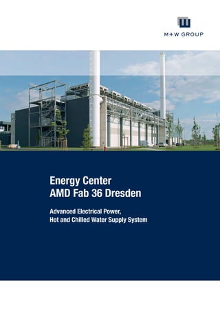
- 1. Energy Center AMD Fab 36 Dresden Advanced Electrical Power, Hot and Chilled Water Supply System
- 2. Economical • Ecological • 100% Reliable AMD has established a second production plant for microprocessor manufacturing in Dresden. When Fab 30 was erected years ago, it was decided by AMD management to get 100% of energy supply by a cogeneration plant (EVC). Encouraged by this favourable experience, AMD Management decided to duplicate the model and to install a second independent Energy Center for supplying 100% of the required energy to the new facility AMD Fab 36. A consortium consisting of the companies Air Liquide GmbH, Düsseldorf and DREWAG Stadtwerke Dresden GmbH received the commission to supply electrical power together with hot and chilled water by the erection and ownership of a Trigeneration plant on a site provided by AMD Fab 36. The consortium commissioned the construction of the plant on the basis of spark ignition engines. Natural gas was selected as fuel to guarantee low environmental impacts. Best values for electrical and total efficiency are achieved by selecting highly efficient components for power generation, heat recovery systems and chilled water generation. System design and module sizing are targeted on lowest primary energy consumption rates at 100% reliability without any interruption. The plant is designed to be operated in parallel to the grid as well as in island mode in case of grid blackouts.
- 3. Scope of Work M+W Group were selected to design, erect and commission the plant to meet the specifications set by AMD Fab 36. The construction phase lasted 13 months. The consortium took over the Plant on April 1st 2005 as planned to deliver the various energies to AMD Fab 36. The plant is designed as a high efficient, closely controlled unit able to provide all necessary supplies to operate a semiconductor manufacturing facility and consists of • supply systems to the plant for natural gas, city water and auxiliary services • gas engine units with associated exhaust heat recovery boilers, heat exchangers and engine cooling loops • direct heated auxiliary boilers (natural gas) for backup • absorption and mechanical chillers with cooling towers • all necessary auxiliary equipment to operate the plant at the designed specification The design has been developed using the experiences gained during the commissioning and operation of the already existing Trigeneration Plant for AMD Fab 30. AMD Fab 36 will ramp up the production during a time period of several years. Therefore the EVC 2 design encompasses two phases for build out. All equipment for phase two will be commissioned under normal operation of the plant without interruptions or excursions in quality of the energies supplied to AMD Fab 36. The systems have been prepared to establish this build out accordingly. Time Schedule According to the requirements of the semiconductor industry the design and construction of the energy center has been accomplished under a fast track approach with the following major milestones: • Start conceptual design November 2003 • Contract award to M+W Group March 08, 2004 • Start earthwork / groundbreaking March 12, 2004 • Start building construction April 19, 2004 • Start MEP installation June 25, 2004 • Building temporarily watertight July 27, 2004 • Start Installation first gas engine unit July 28, 2004 • First firing gas engine unit November 03, 2004 • Mechanical completion December 15, 2004 • Start up mechanical plant January 10, 2005 • Start up of gas engine heat recovery unit February 01, 2005 • Commercial operation of the plant (Handover) March 30, 2005
- 4. Operating Capacities Total design and construction period 17 months until commercial operation. Fine tuning of the plant under operating conditions to achieve the optimum performance of the plant lasting 3 months after handover. Basic assumptions The quality requirements of AMD Fab 36 for the electric power supply cannot be guaranteed by the public 110-kV-grid. In addition, the supply of heat and cold from the heat recovery of electricity generation offers a high efficiency with a minimum of primary energy input. Therefore AMD decided again to be supplied with energy and other media by a dedicated TriGen plant. To ensure the security of supplies and to enable the export of any surplus electrical power, a 110/20-kV-transformer substation with 110-kV-grid supply connection was erected and connected adjacent to the TriGen plant. Required data of the project For the semiconductor manufacturing process AMD requires uninterrupted stable conditions for the following media: Electrical power • voltage • tolerance of voltage • voltage drops • nominal frequency • tolerance of frequency • max. power 20 kV +/- 8% max. 10 ms 50 Hz +/- 1% 22 MW Heat • hot water supply temperature return temperature max. power approx tolerances 80°C 50°C 19 MW +3K / -1K • warm water supply temperature return temperature max. power approx tolerances 32°C 22°C 33 MW +4K / -2K Cold • chilled water supply temperature return temperature max. power approx tolerance 5°C 11°C 9 MW +0.5K /-0.5K • chilled water supply temperature return temperature max. power approx tolerance 11°C 17°C 34 MW +1K / -1K
- 5. General Information Location Building dimensions The plant is located on the west boundary of the AMD Fab 36 site. It is necessary for the main user [AMD Fab 36], the TriGen plant and 110/20-kV-transformer substation to be in close proximity to each other. Main building: • 102 m x 36 m x 14 m • 20 kV building 60 m x 11 m x 11.3 m Water supply and drainage To maintain the levels of process water due to losses of water in the distribution networks, condensation in the evaporative cooling towers and the necessary softening process, water will be used from the public potable water system. Re-using reject water from AMD‘s reverse osmosis treatment plant, hot water supply system, steam generating system, and cooling water system considerably reduces the waste water discharge to public drains. For fire protection, the Energy Center is connected to the fire hydrant main supply from the AMD Fab 36 site. Sanitary waste water and rain water are discharged to public drains. Contaminated waste water is removed through the AMD Fab 36 system and processed prior to disposal into the public system. • including the PCD building 17 m x 11 m x 6.5 m Exhaust stacks with a total height of 48 m are erected on both sides of the main building. To ensure the required atmospheric dilution of exhausted flue gas the total amount of gas engines is split between in 3 groups covering 3 engines each. One of these groups will be erected during phase 2 when a total of 9 engines will be required. In addition to the engines 1 stack is covered by the exhaust of 2 steam back up boilers. To enhance the efficiency of the cooling system, the wet cooling towers are located on the roof of the main plant building.
- 6. Fuel supply system Natural gas is selected as fuel for engines and auxiliary boilers. In the south east of the main building the gas is fed in via a pressure regulator and metering system at a pressure of 4 bar. Engine and waste heat boiler The “hearts” of the Energy Center are the ‘lean burn’ Gas Engine Units (GEUs). During normal operation a total of 8 GEUs operating at approx 85% of the nominal capacity is sufficient to supply the energy needed in maximum by AMD. To guarantee high quality energy supply at 100% availability even when one unit is in failure and a second one is simultaneously in maintenance, the plant is designed for a total of 9 GEUs. In case of a unit failure the remaining GEUs automatically take over the load. A power conditioning device (PCD) ensures consistency in voltage and frequencies spec even during such sensitive take over processes. In addition to electricity and hot water, steam is also supplied by the engines using the jacket water waste heat and the exhaust heat recovery boilers. Warm water is used at 2 temperature levels directly by AMD. Furthermore the energy of hot water and steam is transferred to chilled water at 5°C and 11°C levels by using single and double effect absorption chillers. The total energy efficiency may be extended to a maximum by this “Trigeneration” effect independent of seasonal outside conditions (summer or winter). In case of unbalanced heat capacity and demand a series of back up cooling devices designed as table cooler are located on the roof of the main building. The nominal performance data of each of 9 GEUs are: • nominal electrical power 3,916 kW • natural gas consumption 9,336 kW • heat extraction hot water 95/80°C 2,200 kW • heat extraction steam 9 bars 2,050 kW • nominal electrical efficiency approx 40% • total fuel efficiency above 85% According to the load engine conditions the exhaust temperature may vary from 400°C to 460°C. Before emission to the environment the exhaust is cooled down to approx 100°C by heat recovery systems for steam and hot water generation. The heat recovery steam generators are operated at 180°C/9 to 12 bar levels, the water boilers at 95°C. The electrical energy generated on a 6.3 kV level by the gensets is transformed to 20 kV as requested by AMD. The engines are started by a dedicated compressed air system. The compressed air for the gas engines is maintained by separate compressors and receivers. Auxiliary boiler system For redundancy reasons and to balance between each required media two auxiliary boilers 11.5 MW capacity each are installed for producing steam (180°C, 9 bars (abs). The steam energy may be used either for operating the double effect absorption chillers or for producing hot water by utilising a number of heat exchangers.
- 7. Chilled water system The chilled water system in final build out consists of • 3 double effect absorption chillers for the supply of 5/11°C or 11/17°C (5.8 MW each) • 2 single effect absorption chillers for the supply of 11/17°C (3.2 MW each) • 6 Turbo chillers for the supply of 5/11°C or 11/17°C (5.8 MW each) The steam (180°C, 9 bar) and hot water is used to run absorption chillers. Additional turbo chillers are used for covering summer time peak loads, for redundancy purposes, and for balancing the different energy supply systems (hot and chilled water). The chilled water is supplied by 2 independent systems: • supply / return temperature 5/11°C and • supply / return temperature 11/17°C The chiller waste heat removed by the cooling water system may be reused for supplying heat on a low temperature level at 32°C for preheating purposes during winter time. Waste heat which cannot be used is finally removed to the environment by evaporative cooling towers. Instrumentation and control system An automatic system is used for the plant control and monitoring. The central control room is located in the main building. Environmental protection During operation the environmental conditions required by the local authorities have to be guaranteed. Electrical system Transformers, switchgears and the feeder from the external grid are located in a separate 20 kV building. A further building contains the power conditioning devices (PCD) based on flywheels which are needed to guarantee the exceeding requirements for frequency and voltage control. NO2 CO Dust < 200 ppm < 300 ppm 5 mg/m³
- 8. 02.180.02/05.2011 M+W Group Lotterbergstr. 30 70499 Stuttgart, Germany Phone +49 711 8804-1100 Fax +49 711 8804-1111 energy@mwgroup.net www.mwgroup.net © M+W Germany GmbH Photos: Klaus Schuster