"Federated learning: out of reach no matter how close",Oleksandr Lapshyn
Advanced motion controls 100a8
1. 120A Series
SERIES 120A SERVO AMPLIFIERS
MODELS: 100A8, 100A6, 120A5
FEATURES:
* Surface-mount technology
* Small size, low cost, ease of use
* Optional input signal isolation for
off-the-rectified 120 VAC line operation
* DIP switch selectable:
current, voltage, velocity,
IR compensation, position loop control
* Four quadrant regenerative operation
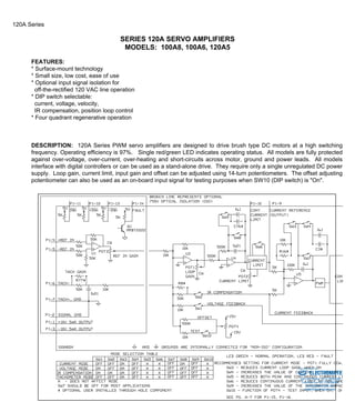
DESCRIPTION: 120A Series PWM servo amplifiers are designed to drive brush type DC motors at a high switching
frequency. Operating efficiency is 97%. Single red/green LED indicates operating status. All models are fully protected
against over-voltage, over-current, over-heating and short-circuits across motor, ground and power leads. All models
interface with digital controllers or can be used as a stand-alone drive. They require only a single unregulated DC power
supply. Loop gain, current limit, input gain and offset can be adjusted using 14-turn potentiometers. The offset adjusting
potentiometer can also be used as an on-board input signal for testing purposes when SW10 (DIP switch) is "On".
Sold & Serviced By:
ELECTROMATE
Toll Free Phone (877) SERVO98
Toll Free Fax (877) SERV099
www.electromate.com
sales@electromate.com
2. 120A Series
MODELS
POWER STAGE SPECIFICATIONS 100A8 100A6 120A5
DC SUPPLY VOLTAGE 20-80V 20-60V 18-50V
PEAK CURRENT (2 sec. max., internally
+100 +100 +120
limited)
MAX. CONT. CURRENT (internally
limited)
+50A +50A +60A
MINIMUM LOAD INDUCTANCE* 200uH
SWITCHING FREQUENCY 22KHZ ±15%
HEATSINK (BASE) TEMPERATURE
RANGE
0o to +65oC; disables if >65oC
OVER-VOLTAGE SHUT-DOWN (self-reset)
86V 62 V 52V
BANDWIDTH 2.5KHz
MECHANICAL SPECIFICATIONS
POWER CONNECTOR Screw terminals
SIGNAL CONNECTOR Molex connector
SIZE (inches) 10.00 x 5.06 x 1.70
WEIGHT 2.5 lb.
* Low inductance motors ("pancake" and "basket-wound") require external inductors.
Sold & Serviced By:
ELECTROMATE
Toll Free Phone (877) SERVO98
Toll Free Fax (877) SERV099
www.electromate.com
sales@electromate.com
3. 120A Series
PIN FUNCTIONS
CONNECTOR PIN NAME DESCRIPTION / NOTES I/O
P1
1 +10V Provides regulated voltages of +/-10V @ 5mA for
customer use. Short circuit protected
O
2 SIGNAL GND
3 -10V
4 +REF IN Differential analog input, maximum ±15V, 50K
input resistance
I
5 -REF IN
6 -TACH IN Maximum ±60V analog, 60K input resistance I
7 +TACH (GND)
8 CURRENT
MONITOR
This signal is proportional to the actual current in
the motor leads. Scaling is 1V=16A when
SW5=On (full current), 1V=8A when SW5=Off
O
9 CURRENT REF Command signal to the internal current-loop.
The maximum peak current rating of the amplifier
equals 7.5V at this pin
O
10 CONTINUOUS
CURRENT
LIMIT
Can be used to reduce the factory-preset
maximum continuous current limit
I
11
INHIBIT
Inhibit. TTL, turns off all four mosfets of the "H"
bridge drive when pulled to ground. For inverted
inhibit inputs, see section "G".
I
12
+INHIBIT
Inhibits the motor for "+" direction only. This
function can be useful to drive the motor off from
a "limit switch"
I
13
-INHIBIT
Inhibits the motor for "-" direction only. This
function can be useful to drive the motor off from
a "limit switch"
I
14 FAULT
(red LED)
TTL compatible output. It becomes high during
output short-circuit, over-voltage, over-heating,
inhibit, and during "power-on reset". Fault
condition indicated by red LED
O
15 SYNCH IN Used for synchronizing the switching frequency
of several amplifier modules. Consult factory for
this option. Not applicable for "ISO" option. In
the "ISO" option pin 16 is connected to power
ground and can be used as ground with P1- 8,9
N/A
16 SYNCH OUT
Sold & Serviced By:
ELECTROMATE
Toll Free Phone (877) SERVO98
Toll Free Fax (877) SERV099
www.electromate.com
sales@electromate.com
4. 120A Series
SWITCH FUNCTIONS
SWITCH FUNCTION DESCRIPTION SETTING
ON OFF
1 Internal voltage feedback On Off
2 Internal current feedback for IR compensation On Off
3 Current loop gain Decrease Increase
4 Current loop integration Increase Decrease
5 Current scaling.
When "Off", increases sensitivity of current sense
thus reducing both peak and continuous current
limit by 50% (see section "G")
Full-current Half-current
6 Can be used to reduce factory-preset maximum
continuous current limit (see section "G")
Cont./Peak
Ratio 25%
Cont./Peak
Ratio 50%
7 It is recommended to leave SW7 in "Off" position Shorts out the
current loop
integrator
capacitor
Current loop
integrator
operating
8 This capacitor normally ensures "error-free"
operation by reducing the error-signal (output of
summing amplifier) to zero
Shorts out the
outer velocity /
voltage loop
integrator
capacitor
Velocity/
Voltage
integrator
operating
9 Increases the value of the integrator capacitor. It is
recommended to leave SW9 in "Off" position for
most applications
Increase Decrease
10 Offset / test. Sensitivity of the "offset" pot. Used as
an on-board reference signal in test mode
Increase Decrease
POTENTIOMETER FUNCTIONS
POTENTIOMETER DESCRIPTION TURNING CW
Pot 1 Loop gain adjustment in voltage & velocity modes.
Voltage to current scaling factor adjustment in current
mode
Increases loop gain
Pot 2 Current limit. It adjusts both continuous and peak
current limit by maintaining their ratio
Increases current
limit
Pot 3 Reference gain. It adjusts the ratio between input
signal and output variables (voltage, current, velocity)
Increases reference
input gain
Pot 4 Offset / test. Used to adjust any imbalance in the input
signal or in the amplifier. When SW10 (DIP switch) is
"On", the sensitivity of this pot is greatly increased thus
it can be used as an on-board signal source for testing
purposes
N/A
Sold & Serviced By:
ELECTROMATE
Toll Free Phone (877) SERVO98
Toll Free Fax (877) SERV099
www.electromate.com
sales@electromate.com
5. 120A Series
TEST POINTS FOR POTENTIOMETERS
See section "G"
PLUG-IN-AND-USE TEST MODE
Advanced Motion Controls' 100A Series amplifiers can operate in a DIP switch selectable "Test Mode" to facilitate
evaluation and installation (SW 1, 3, 10 = On; SW 2, 4, 7, 8, 9 = Off). This is "voltage amplifier mode" with on-board
potentiometer adjustable reference. See section "G" for powering-up in test mode.
OPTIONAL INPUT SIGNAL ISOLATION
These amplifiers can be ordered with an internally installed analog isolation amplifier which optically isolates the inputs
and inhibit lines from the remainder of the amplifier circuitry ("ISO" option). See block diagram on data sheet (page A-5).
This optional input isolation facilitates off-the-rectified-line operation. Isolation is necessary in transformerless
applications to isolate controller signal ground (often the same as earth ground) from DC power ground. The isolation
option may also reduce system noise. This option is generally not required with isolated power supplies.
OPERATING MODE SELECTION
These modes can be selected by the DIP switches according to the chart in the functional block diagram:
* Current Mode
* Voltage Mode
* IR Compensation Mode
* Tachometer Mode
See section "G" for more information.
CURRENT LIMIT ADJUSTMENTS
These amplifiers feature separate peak and continuous current limit adjustments.
The current limit adjusting Pot 2 adjusts both peak and continuous current limit at the same time. It has 12 active turns
plus 1 inactive turn at each end and is approximately linear. Thus, to adjust the current limit, turn the potentiometer
counter-clockwise to zero (using ohmmeter), then turn clockwise to the appropriate value. Pin P1- 9 is the input to the
internal current amplifier stage. Since the output current is proportional to P1- 9, the adjusted current limit can easily be
observed at this pin. The maximum peak current value equals 7.5V at this pin. The actual current can be monitored at
pin P1- 8. If the desired limit is, for example, 50 amperes, and the servo amplifier peak current is 100 amperes, turn the
potentiometer 7 turns clockwise from zero.
The continuous current limit can be reduced without affecting the peak current limit by connecting an external current
limiting resistor R-lmt between P1-10 and P1- 2. See table below.
CURRENT LIMITING RESISTOR 40K 20K 3K 1K 0 K
CONTINUOUS CURRENT LIMIT 90% 80% 50% 30% 10%
Sold & Serviced By:
ELECTROMATE
Toll Free Phone (877) SERVO98
Toll Free Fax (877) SERV099
www.electromate.com
sales@electromate.com
6. 120A Series
SW6 (DIP switch) will reduce the continuous current limit to 50% of the maximum value, when switched "On". SW5 (DIP
switch) will reduce the current feedback (monitor) scaling by 50%, thereby reducing both the peak and the continuous
current limit by 50%, when switched "Off".
See section "G" for more information
TYPICAL SYSTEM WIRING: See section "G"
ORDERING INFORMATION
Models: 120A5X, 100A6X, 100A8X
With isolation: 120A5IX, 100A6IX, 100A8IX
X indicates the current revision number.
MOUNTING DIMENSIONS: See below.
Sold & Serviced By:
ELECTROMATE
Toll Free Phone (877) SERVO98
Toll Free Fax (877) SERV099
www.electromate.com
sales@electromate.com
7. 120A Series
Sold & Serviced By:
ELECTROMATE
Toll Free Phone (877) SERVO98
Toll Free Fax (877) SERV099
www.electromate.com
sales@electromate.com