Hot Sexy call girls in Pira Garhi🔝 9953056974 🔝 escort Service
95ZJ_13.PDF
1. ZJ FRAME AND BUMPERS 13 - 1
FRAME AND BUMPERS
CONTENTS
page page
BUMPERS . . . . . . . . . . . . . . . . . . . . . . . . . . . . . . 2 FRAME . . . . . . . . . . . . . . . . . . . . . . . . . . . . . . . . . 1
FRAME
GENERAL INFORMATION
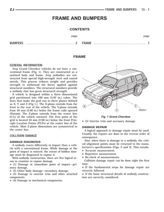
Jeep Grand Cherokee vehicles do not have a con-
ventional frame (Fig. 1). They are constructed as a
unitized body and frame. Jeep unibodies are con-
structed from special high-strength steel and coated
metals. This process reduces weight and provides
strength to withstand the forces applied against
structural members. The structural members provide
a unibody that has great structural strength.
A vehicle is designed within a three dimensional
grid partitioned into 100 mm (3.92 in.) cubes. The
lines that make the grid run in three planes defined
as X, Y and Z (Fig 1.). The X-plane extends from the
front to the rear of the vehicle. The Y-plane extends
from 50 mm (2.00 in.) below the frame rails upward
(Datum). The Z-plane extends from the center line
(C/L) of the vehicle outward. The Zero point of the Fig. 1 Grand Cherokee
grid is located 50 mm (2.00 in.) below the front Prin- • (5) Interior trim and accessory damage.
ciple Location Points (PLPs) at the center line of the
vehicle. Most Z-plane dimensions are symmetrical to DAMAGE REPAIR
the center line. A logical approach to damage repair must be used.
Usually, the repairs are done in the reverse order of
COLLISION DAMAGE consequence.
Also, when there is damage to a unibody, the criti-
DAMAGE DIAGNOSIS
A unibody reacts differently to impact than a vehi- cal alignment points must be returned to the manu-
cle with a conventional frame. While damage at the facturer’s specifications (Figs. 2 and 3). This entails:
point of impact is noticed, the extent of hidden dam- • Accurate measurement.
age must be diagnosed to expose it. • Repetitive measurement.
With unibody construction, there are five logical ar- • Re-check of measurements.
eas to examine to expose damage. Collision damage repair can be done right the first
• (1) Damage at immediate point of impact—pri- time:
mary damage. • If the fundamental steps for damage repair are
• (2) Other body damage—secondary damage. correctly followed.
• (3) Damage to exterior trim and other attached • If the basic structural details of unibody construc-
components. tion are correctly considered.
• (4) Damage to mechanical components.
4. 13 - 4 FRAME AND BUMPERS ZJ
BUMPERS
INDEX
page page
Front Bumper/Fascia . . . . . . . . . . . . . . . . . . . . . . . . 4 Rear Bumper Fascia . . . . . . . . . . . . . . . . . . . . . . . . 6
Front Tow Hooks . . . . . . . . . . . . . . . . . . . . . . . . . . . 4 Rear Tow Hook . . . . . . . . . . . . . . . . . . . . . . . . . . . . 6
Rear Bumper . . . . . . . . . . . . . . . . . . . . . . . . . . . . . 5
FRONT BUMPER/FASCIA
GENERAL INFORMATION
The Grand Cherokee front bumper is actually a
bumper fascia incorporated with a lower welded
crossmember. The lower crossmember is a fixed
welded structure. To replace the crossmember a
frame machine should be used to correctly align the
crossmember to the unibody.
REMOVAL
(1) Remove grille screws at grille opening rein-
forcement (GOR) (Fig. 1).
(2) Unsnap lower clips at grille. Remove grille from
(GOR).
(3) Remove turn signals, side markers and head-
Fig. 2 Lower Fascia Removal
lamps. Refer to Group 8L, Lamps for service informa-
tion.
(4) Remove the retainers at the front fascia (Fig.
2).
(5) Remove the plastic rivets at each front wheel
well (Fig. 3).
(6) Slide the fascia off of the retainer pegs at the
side of the fender attach brackets. Using a small
screwdriver, pull up on locating tangs under turn sig-
nal mounting location.
(7) Remove the fascia from the vehicle (Fig. 2).
Fig. 3 Wheel Well Retainers
FRONT TOW HOOKS
REMOVAL
(1) Remove the nuts and bolts that attach the tow
hooks to the lower crossmember (Fig. 4).
(2) Remove the tow hooks from the lower cross-
member (Fig. 4).
Fig. 1 Grille Removal
Reverse removal procedure for installation.
5. ZJ FRAME AND BUMPERS 13 - 5
(10) Remove the lower retainers from the bumper
fascia (Fig. 6).
(11) Remove the bumper fascia from the bumper.
INSTALLATION
(1) Install brackets onto bumper beam.
(2) Install beam/brackets onto vehicle rails finger-
tight (Fig. 6).
(3) Install fascia onto bumper assembly (Fig. 6).
(4) Check gaps and fit. Adjust as necessary.
Tighten bolts to 56 N⅐m (41 ft-lbs).
(5) Install scuff pad (Fig. 6).
(6) If removed, install the trailer hitch. If neces-
sary, refer to the installation procedure within Group
23, Body Components.
Fig. 4 Tow Hook Removal
INSTALLATION
(1) Position the tow hooks at the lower crossmem-
ber. Install the bolts and nuts that attach tow hooks Fig. 5 Bumper Support Bracket
(Fig. 4). Tighten the retaining nuts to 100 N⅐m (74 ft-
lbs) torque.
REAR BUMPER
REMOVAL
(1) For vehicles equipped with a trailer hitch, re-
move the hitch before removing the bumper. If neces-
sary, refer to the removal procedure within Group 23,
Body Components.
(2) Raise and support the rear of the vehicle.
(3) Support the bumper.
(4) Remove push-in retainers at each side rear
wheel well.
(5) Remove the bolts that attach the bumper sup-
port brackets to the rear rails (Fig. 5).
(6) Slide the bumper beam/fascia off of the retainer
pegs on the side of the lower quarter panel.
(7) Remove the beam/fascia from the vehicle.
(8) Remove the bumper support brackets from the
bumper (Fig. 6).
(9) Remove the upper scuff pad from the bumper
fascia by squeezing fasteners and pushing through Fig. 6 Bumper Removal
slots.(Fig. 6).
6. 13 - 6 FRAME AND BUMPERS ZJ
REAR BUMPER FASCIA
REMOVAL
(1) For vehicles equipped with a trailer hitch, re-
move the hitch before removing the bumper fascia. If
necessary, refer to the removal procedure within
Group 23, Body Components.
(2) Raise and support the rear of the vehicle.
(3) Remove the upper scuff pad from fascia (Fig.
6).
(4) Remove the lower retainers from fascia (Fig. 6).
(5) Remove the push-in retainers located at the
rear wheel well on each side.
(6) Remove the fascia from the bumper.
For installation, reverse removal procedure.
REAR TOW HOOK
REMOVAL
(1) Remove the nuts and bolts that attach the tow
hook to the lower crossmember (Fig. 7).
(2) Remove the tow hook from the lower crossmem-
Fig. 7 Tow Hook Removal
ber (Fig. 7).
INSTALLATION
(1) Position the tow hook at the lower crossmem-
ber. Install the bolts and nuts that attach tow hook
(Fig. 7). Tighten the retaining nuts to 100 N⅐m (74 ft-
lbs) torque.