SlideShare a Scribd company logo
1 of 37
Download to read offline
Zion Nuclear Power Station Decommissioning Project
Removing & Segmenting the Reactor Vessel Internals and Segmenting the
Reactor Vessel.
(A condensed pictorial historical record)
(or “How to Remove your Nuclear Reactor Vessel in 743 Easy Steps” - A DIY Project)
Presentation Notes and Disclaimers
This presentation is NOT the work of any current Siempelkamp L.P., ZionSolutions or Energy Solutions employee and should in no way
be associated with the image or reputation of any of these corporations. This is the effort of a single former employer of Siempelkamp
who is proud of the work our teams accomplished and wanted to create a visual record of this work.
The removal and segmentation of the various components of the Reactor Vessel Internals (RVI) and the segmentation of the Reactor
Vessel (RVS) itself, was contracted out to Siempelkamp L.P. by ZionSolutions.
Siempelkamp L.P. is an engineering and specialized equipment manufacturer based in Germany.
This presentation provides a limited visual historical record of many of the activities of the Siempelkamp RV Segmentation Crew and
some of the ZionSolutions Decommissioning Crew at the Zion Nuclear Power Station during the decommissioning work that occurred
on-site from 2014 – 2015. A few of the images taken before 2014 are included to provide context for the RVI and RVS work.
Most of the images shown were taken by members of the Siempelkamp Segmentation Crew and do not represent the entire scope of
work that was performed during the removal and segmentation of the Reactor Vessel Internals (RVI) or the Reactor Vessel Segmentation
(RVS) phase of the decommissioning work. Other images were collected from Internet sources and may be copyrighted.
Please note that this presentation has been stripped down to fit into the 100MB limit (in this case, 37 pages) that Linked-In imposes for
uploaded Presentations, so there are gaps in the processes as my original Presentation filled 97 pages. The 97 page Presentation is
available for former Siempelkamp & Zion Solution crew members if they would like to contact me. After contact, you can mail a Flash
drive to me or I can burn a CD with the entire 288MB file for you.
The Zion Nuclear Power Station’s first unit began operation in December of 1973 and both PWR units were retired from operation on
February 13, 1998. All nuclear fuel rods were removed from the reactor vessel and placed in the plant's on-site spent fuel pool by
March 9, 1998.
There were plans to keep the facility in long-term safe storage (SAFSTOR) until Unit 2's operating license expired on November 14,
2013. However, on August 23, 2010, it was announced that the Nuclear Regulatory Commission (NRC) had approved the transfer of
Exelon's (ComEd's parent company) license to EnergySolutions of Salt Lake City. In 2011, ZionSolutions (a subsidiary of
EnergySolutions) began decommissioning operations. Therefore, the residual radiation levels in and around the reactor vessel were
allowed to decay for around 13 years which had a significant impact on reducing personnel radiation dosage rates during the
Reactor Vessel Internals (RVI) and RV Segmentation (RVS) work.
The original estimated date for decommissioning closure was December 31, 2026.
Archive Image of the Zion Nuclear Power Station
as viewed from a beach on Lake Michigan
Finally breaking through the inside layer of concrete and rebar.
Breaking through the concrete to another layer of rebar.
One of the earlier major tasks for ZionSolutions was to cut a large equipment removal opening
through the four foot thick Containment Building wall. The opening in Unit 1, with the sliding “Barn
Doors” that were installed to restrict the spread of airborne contamination, is visible in the image
above. (with the white doors partially opened) Also, you can see the several of the vertical green
enclosures around the containment building tendons have been partially removed to provide access
for the tendon removal. The tensioning had to be removed before an opening could safely be cut
through that area of the containment wall and this will eventually be done for the entire structure. Breaking through to the first layer of rebar in Unit 2.
Images of Zion Station During the Cutting of the Equipment Removal Opening in the Containment Buildings
After removing the Reactor Head, the reactor internals were removed
and placed in the reactor cavity. The reactor cavity had been flooded
with borated water to provide shielding for the segmentation of the
internals which was performed under water to reduce radiation
exposure to the workers performing the RVI segmentation.
The Reactor Vessel Internals were segmented into many smaller
pieces that were then placed into the appropriate type of radwaste
container for permanent disposal.
The Reactor Vessel Segmentation plan had been to cut the RV into 3
sections, the Nozzle Level, which would be done first, the Belt-Line
Level would be next and each of these levels would be further
segmented around their circumference into 8 smaller segments as
shown in some of the following images. The Hemispherical Bottom
Head (HBH) would then be the last piece to be further segmented into 3
smaller segments; at least, that was the original plan.
Upper and
Lower RV
Internals
The Zion Station Reactor Vessel Upper Internals
Nozzle
Level
Hemispherical
Bottom Head
(HBH)
Belt-Line
Level
RV Segmentation
Levels
Removal of the Reactor Head and the Beginning of the RVI Phase
The Volume Reduction Station (VRS) in the test pit facility at In-Place
Machining in Milwaukee, Wisconsin
The Volume Reduction Station (VRS) in the Mock-up area showing the 38i circular saw
used to down-size reactor internal components for shipping.
The Volume Reduction Station (VRS) is designed to segment the various components of the reactor vessel internals (Baffle Plates, Fuel Alignment Plate, Core
Shroud, Core Barrel, etc) into pieces small enough to fit into the appropriate category of Radwaste liner (3-60B, 24PT4, etc). The horizontal reciprocating saw,
used for making long cuts, is visible in the left image.
After the RVI components had been segmented and packed in the appropriate Radwaste containers, they were shipped out by truck and train for long term
burial at the Clive, Utah site and/or other sites. The spent fuel rods are stored at the Zion ISFSI in 61 containers along with 4 containers of Greater Than Class
C (GTCC) waste collected during the reactor internals segmentation process and other decommissioning processes.
The Zion Independent Spent Fuel Storage Installation (ISFSI)
To date, I have been able to gather
only these few images of the
Reactor Vessel Internals (RVI)
segmentation activities from our
crew. If additional images are
provided to me in the future, I can
add them to this file.
This is the end of the RVI portion of
this presentation
A GTCC waste container with Baffle Plates and other GTCC
waste material cut to fit by the VRS.
The Plan is to sequentially cut all 8 “L” shaped cuts through the Reactor Vessel
Wall where the Pre-Cuts had been made through the thicker upper RV wall.
After attaching the Turnable Gripper to the desired reactor segment, the final
short horizontal cut is made between the two “L” cuts to free the segment.
During the cutting of all 8 “L” cuts & Final Cuts the Suction Duct is removing the
gases from the flame cutting and any airborne contamination to the HEPA filter.
The Turnable Gripper (TGR), which is attached to the Polar Crane, then lifts the
freed-up segment up through the opening in the Outer Shielding Plate (OSP)
and places the segment in a Shielded Box for disposal as radwaste.
Next, the Sand Box Covers needed to be removed to provide
access to the area between the RV wall and the Bio-Shield.
Hand-held plasma cutters were utilized to burn through the
Sand Box cover welds so the covers could be removed
Concrete blocks that provided additional shielding were removed from the Sand Boxes to provide access to the reactor coolant pipes so that they could be
cut at the nozzles with a combination of wire saws and plasma cutters.
Next, the concrete bridges that secured the top of the RV to the structure needed to be removed before the reactor coolant nozzle pipes could be cut.
A jig was designed and fabricated to hold the concrete bridge in place during the cutting with
the abrasive diamond wire saw until the concrete could be removed with a crane.
A concrete bridge can be seen at
the top of the above image.
Installing the wire saw to cut each
concrete bridge.
Wire saw marks from the concrete bridge removal. The concrete bridges were placed in a Super
Sack for disposal.
With the concrete bridges now removed, the borated concrete around the
outside of the RV was completely accessible to cut with the wire saw.
The Polar Crane was then rigged to each borated concrete section for removal
The borated concrete was cut on the centerline of each RV nozzle to
free up each section for removal.
The process of the initial vessel drain-down began by removing the Shielding Plate (SP) and replacing it with one half of the Inner Shielding Plate (ISP).
This arrangement provided shielding for workers who installed the Tri-Nuc pump and drained the borated water down to a level below the vessel nozzles so that
the cutting of the RV coolant loop pipes could commence.
As the water was drained down in the RV, the nozzle openings were backwashed to flush as much radioactive sediment as possible out of the nozzle
openings and into the bottom of the RV, where the remaining water provided some shielding during the remaining operations.
Most of the circumference of each of the eight reactor coolant loop pipes is cut by the ABS from the bottom-up with the top “stitch” being cut with a hand-held
plasma cutter.
Installing the abrasive wire saw (ABS) to cut the bottom of the reactor coolant loop pipes
The next step in the process was to start cutting the reactor coolant loop pipes.
Here we have our team working at the peak of efficiency. The worker on
the bottom is welding a shield plate into the RV nozzle to reduce
radiation expose, while the worker in the middle is completing the loop
cut using a hand-held plasma cutter.
While in another area, the removal of the Seal Ledge continues. (you can
see the remaining seal ledge has not been removed above the worker
welding in the plugs.)
Once all the reactor coolant loop pipes were removed, clearance
checks were performed to assure the Flame Cutting System (FCS)
could travel unobstructed around the circumference of the RV with
adequate clearance from the nozzles.
The initial vessel drain-down lowered the water level in the RV to
less than a foot below the RV nozzle openings.
The other half of the Inner Shielding Plate (ISP) was placed on
the RV in preparation for the Final Drain-down.
The Tri-Nuc pump was brought back into the reactor vessel and
lowered to the bottom of the RV.
The view looking down into the RV with the water drained.
You can see the In-Core Instrumentation (ICI) conduit stubs in the bottom of
the reactor vessel that remained full of water and will be drained later.
The TSP Base Frame assembly was completed by installing the Vertical
Shielding Plates and Liners and then the assembled frame was flown
down with the Polar Crane and installed on top of the Reactor Vessel.
Next, the Outer Shielding Plate (OSP) was assembled on the Support
Platform. The OSP contains the Flame Cutting System mast assembly
that drives the flame cutter and the Ventilation Flaps that cover the
opening in the OSP from which the cut RV Segments will be removed.
The Outer Shielding Plate (OSP) assembly was then installed on top
of the TSP Base Frame on the Reactor Vessel and the electrical and
gas line connections were completed.
The Flame Cutting
System (FCS) mast
was installed vertically
on the OSP.
Installing the Turnable Shield Plate and the Flame Cutting System
The mast will travel down outside the RV wall to burn the vertical cut and then
travel horizontally along the track to complete the “L” shaped cuts in the RV. Making the final gas and electrical connections to the FCS Mast.
The Flame Cutting System (FCS) Mast
“Git er’Dun”
OUTSTANDING
WORK!
Raising the LR up with the Chellino.
Swinging the LR up and in with the Chellino. Connecting the LR to the Polar Crane.
Doing the Coordinated Crane Dance with both cranes
Bringing the Lifting Rod into Unit 1 with the Chellino & Polar Cranes
Flying the Strand Jack System (SJS) bridge into position.
Due to the weight hoisting limits and horizontal reach of the available cranes in the Containment Building (Polar Crane & Knuckle Boom Cranes) an
engineered solution to raising the RV and moving the heavy RV segments (21 – 22 tons) had to be achieved.
Since only the Polar Crane had the weight capacity to safely lift the RV segments that would be cut from the RV and the reach to place them in the shielded
boxes, another method of lifting the entire RV had to be developed.
The Siempelkamp engineered solution became known as the Strand Jack System (SJS) that included the Strand Jack Bridge. The bridge was placed across
the center of the RV, then a set of 4 hydraulic jacks were attached to the bridge. Each of these four jacks were connected to the lifting rod by about 15 steel
cables. The hydraulic jacks lifted the RV up to the various cutting levels, which freed up the Polar Crane to lift out each RV segment and place them in
shielded boxes using the Turnable Gripper (TGR). The assembly of this system is shown in the next series of images.
ABOUT THE STRAND JACK SYSTEM
The Strand Jack System (SJS) bridge in position.
The
assembled
Strand Jacks
were moved
into position
with the Polar
Crane and the
Knuckle
Boom Crane.
Maneuvering the Strand Jacks into position on the SJS Bridge.
Precise communication between the Polar Crane and the Knuckle Boom
crane operators was crucial to safely installing the equipment.
All 4 jacks were installed. As the RV is lifted,
those strands sticking out of the top of the Jacks
were managed with a loosely tied rope to keep
the strands from splaying out.
The Lifting Eyes are now ready to be attached to the LR so the RV can be
raised to the first level cutting position with the Strand Jacks.
The Lifting Eyes are now attached
to the top of the LR.
The Flame Cutting System performing the test cuts as viewed from
a camera outside the RV.
The flame cutting slag plume being blown into the RV as viewed
from a camera inside the RV.
The Flame Cutting System performing the test cuts as viewed from flame cutting head camera.The Flame Cutting System performing the test
cuts as viewed from a camera outside the RV.
The Flame Cutting System (FCS) performing the “L” cuts as
viewed from a camera above the RV.
The flame cutting blast plume as viewed from a camera inside
the RV.
The view from the cutting head camera after finishing the
vertical part of the “L” cut.
Monitoring the RV cutting process from the monitors inside the
Control Station.
And here comes the first segment now.
It’s greeted by a standing room only crowd.
A view of the Flame Cutting Head through the Gripper opening
making the Final Cut to free a segment.
These boxes in the shallow end are ready to receive the RV Nozzle segments. Other boxes have been positioned in the Deep End also. Once the first 4
boxes were filled they were moved out of the RV Cavity and 4 more empty boxes replaced these.
Then the Polar Crane, with the Gripper attached, moves the RV
segment across the RV cavity into a shielded box.
Meanwhile, the ventilation system has been purging the flame cutting
gases and any airborne contamination through the HEPA Filter. Then the OSP
rotates to a position over the next segment to be cut on the opposite side from
the first to attempt a balanced load. The TGR grabs the next segment and the
Final Cut is again made. Then the Vent Flaps on the OSP are opened and the
next segment is removed through the opening in the OSP. This process
continued for all 8 segments.
The view from inside the RV after the first RV segment
was removed by the Gripper.
Once filled, the shielded box covers were bolted back onto the box. The filled boxes were moved to the HLRS with the Polar Crane.
“Going Up? The filled boxes waiting to be moved outside
Unit 1 containment on the HLRS Cart.
On this particularly windy day the boxes waited on the HLRS
Cart until the wind died down the next day so they could be
safely moved to the ground by the crane.
The filled boxes get rolled out of the Unit 1 containment building
on the HLRS.
The filled boxes outside the Unit 1 containment building awaiting shipping.
The filled boxes outside the containment building being moved off the HLRS
by the Chellino crane.
As the Nozzle boxes were being removed from containment,
preparations for the Belt-Line cuts continued. The Strand Jacks raised
the remaining reactor vessel up to the next cutting level.
A Nuclear Safety Related (NSR) Sharpie was used
to mark the cutting lines for the Belt-Line cuts.
Maintenance was performed on the Flame Cutting System and
the clearances were again checked.
The sequential series of “L” shaped cuts was again performed and
then the final cuts began.
The first Belt-Line segment starting to come out past the vent flaps. Flying it up with the Gripper.
Flying it up past the Strand
Jacks on its way over to the
Dance Floor.
(Note the increased lengths
of the strands exiting the top
of each Strand Jack)
Placing the Belt–Line segment in
“The DownEnder”.
Placing the first Belt-Line segment in
the shielded box. (concave side up)
The next Belt-Line
segment was placed in
the DownEnder.
The second Belt-Line segment
being laid horizontal.
The second segment being moved
into the same shielded box
(concave side down) using the
Aux. hook on the Polar Crane.
Note that keeping the inside of the
RV segments facing each other
(concave to concave) reduces the
overall radiation that the box has
to shield against, thus reducing the
box weight & cost.
When the Lifting Adapter is installed on the top of the LR/HBH assembly, the Polar
Crane main hook is attached to the Lifting Adapter. So now the load is on the Polar
Crane’s main hook, which was previously needed to remove the RV segments. The
Aux. hook on the Polar Crane is then rigged to the two HOT beams as seen above.
The Aux. hook on the Polar Crane then moves the HOT beams off
to each side. Note: you can see the SJS has been moved out of
the way in the background of the above image.
Now the Polar Crane lifts up the LR/HBH assembly with the main hook, up between the HOT beams, up past the SJS and over to the “Beach” where it will be
welded to the HBH Stand.
The Polar Crane moving the HBH over to the “Beach” where it will be welded to the HBH Stand.
The HBH sitting on the HBH Stand with the corner posts welded to the stand.
The crew welding the steel shielding cover onto the HBH in order to reduce radiation during transport.
After the Siempelkamp crew caulks the circumference of the cover plate
to make an airtight seal, they begin rigging to HBH to the Polar Crane
All rigged and ready to go out of containment.
Time for some pictures, we’re almost done.
The last piece of the Unit 1 Reactor Vessel, the Hemispherical Bottom Head (HBH)
being loaded on a flatbed truck and then wrapped for the long haul to its final burial site.
On 12/16/2015, the 62.85 ton Unit 1 - Hemispherical Bottom Head (HBH) was shipped off the
Zion site on this 34 wheeler flatbed truck to its final burial location.
On 07/30/2015, the Unit 2 -
Hemispherical Bottom Head
(HBH) that weighed a little under
63 tons was shipped off the Zion
site on this 34 wheeler flatbed
truck to its final burial location.
The Siempelkamp Crew

More Related Content

What's hot

Module 1 Behaviour of RC beams in Shear and Torsion
Module 1   Behaviour of RC beams in Shear and TorsionModule 1   Behaviour of RC beams in Shear and Torsion
Module 1 Behaviour of RC beams in Shear and TorsionVVIETCIVIL
 
Bridges and its Types & Components by Chetan Bisht
Bridges and its Types & Components by  Chetan BishtBridges and its Types & Components by  Chetan Bisht
Bridges and its Types & Components by Chetan BishtChetanBisht16
 
Chapter 14 bridge hydraulics
Chapter 14 bridge hydraulicsChapter 14 bridge hydraulics
Chapter 14 bridge hydraulicsmarco tacco
 
Retaining wall/level backfill
Retaining wall/level backfillRetaining wall/level backfill
Retaining wall/level backfillTimóteo Rocha
 
Footing design
Footing designFooting design
Footing designYasin J
 
SITE VISIT REPORT
SITE VISIT REPORTSITE VISIT REPORT
SITE VISIT REPORTWan Nee
 
Dredging Techniques and dredgers
Dredging Techniques and dredgersDredging Techniques and dredgers
Dredging Techniques and dredgersamansingh2914
 
Industrial flooring by tremix vacuum system
Industrial flooring by tremix vacuum systemIndustrial flooring by tremix vacuum system
Industrial flooring by tremix vacuum systemHebin Chiriyankandath
 
Statistical quality control
Statistical quality controlStatistical quality control
Statistical quality controlshalomjudit3
 
Design of RCC Column footing
Design of RCC Column footingDesign of RCC Column footing
Design of RCC Column footingArun Kurali
 
Design of Rubble Mound Seawall
Design of Rubble Mound SeawallDesign of Rubble Mound Seawall
Design of Rubble Mound SeawallSHAILESH SHUKLA
 
Explain with example the structural and non structural mitigation programs ta...
Explain with example the structural and non structural mitigation programs ta...Explain with example the structural and non structural mitigation programs ta...
Explain with example the structural and non structural mitigation programs ta...Jahangir Alam
 
Sheet pile (usefulsearch.org) (useful search)
Sheet pile (usefulsearch.org) (useful search)Sheet pile (usefulsearch.org) (useful search)
Sheet pile (usefulsearch.org) (useful search)Make Mannan
 
Design of two way slabs(d.d.m.)
Design of two way slabs(d.d.m.)Design of two way slabs(d.d.m.)
Design of two way slabs(d.d.m.)Malika khalil
 
Ground Response Analysis - Geotechnical Earthquake engineering
Ground Response Analysis - Geotechnical Earthquake engineeringGround Response Analysis - Geotechnical Earthquake engineering
Ground Response Analysis - Geotechnical Earthquake engineeringCristian Soriano-Camelo
 
Connections in steel structures
Connections in steel structuresConnections in steel structures
Connections in steel structuresRizwan Khurram
 
Geotechnical Engineering-II [Lec #18: Terzaghi Bearing Capacity Equation]
Geotechnical Engineering-II [Lec #18: Terzaghi Bearing Capacity Equation]Geotechnical Engineering-II [Lec #18: Terzaghi Bearing Capacity Equation]
Geotechnical Engineering-II [Lec #18: Terzaghi Bearing Capacity Equation]Muhammad Irfan
 

What's hot (20)

Module 1 Behaviour of RC beams in Shear and Torsion
Module 1   Behaviour of RC beams in Shear and TorsionModule 1   Behaviour of RC beams in Shear and Torsion
Module 1 Behaviour of RC beams in Shear and Torsion
 
Bridges and its Types & Components by Chetan Bisht
Bridges and its Types & Components by  Chetan BishtBridges and its Types & Components by  Chetan Bisht
Bridges and its Types & Components by Chetan Bisht
 
Chapter 14 bridge hydraulics
Chapter 14 bridge hydraulicsChapter 14 bridge hydraulics
Chapter 14 bridge hydraulics
 
Retaining wall/level backfill
Retaining wall/level backfillRetaining wall/level backfill
Retaining wall/level backfill
 
Footing design
Footing designFooting design
Footing design
 
SITE VISIT REPORT
SITE VISIT REPORTSITE VISIT REPORT
SITE VISIT REPORT
 
Dredging Techniques and dredgers
Dredging Techniques and dredgersDredging Techniques and dredgers
Dredging Techniques and dredgers
 
Industrial flooring by tremix vacuum system
Industrial flooring by tremix vacuum systemIndustrial flooring by tremix vacuum system
Industrial flooring by tremix vacuum system
 
Statistical quality control
Statistical quality controlStatistical quality control
Statistical quality control
 
COMPARISON OF WIND LOAD ALONG WITH BNBC 1993, BNBC 2020.pptx
COMPARISON OF WIND LOAD ALONG WITH BNBC 1993, BNBC 2020.pptxCOMPARISON OF WIND LOAD ALONG WITH BNBC 1993, BNBC 2020.pptx
COMPARISON OF WIND LOAD ALONG WITH BNBC 1993, BNBC 2020.pptx
 
Design of RCC Column footing
Design of RCC Column footingDesign of RCC Column footing
Design of RCC Column footing
 
Design of Rubble Mound Seawall
Design of Rubble Mound SeawallDesign of Rubble Mound Seawall
Design of Rubble Mound Seawall
 
Explain with example the structural and non structural mitigation programs ta...
Explain with example the structural and non structural mitigation programs ta...Explain with example the structural and non structural mitigation programs ta...
Explain with example the structural and non structural mitigation programs ta...
 
Chapter 4 embankment dams
Chapter 4 embankment damsChapter 4 embankment dams
Chapter 4 embankment dams
 
Sheet pile (usefulsearch.org) (useful search)
Sheet pile (usefulsearch.org) (useful search)Sheet pile (usefulsearch.org) (useful search)
Sheet pile (usefulsearch.org) (useful search)
 
Types of cracks in concrete
Types of cracks in concreteTypes of cracks in concrete
Types of cracks in concrete
 
Design of two way slabs(d.d.m.)
Design of two way slabs(d.d.m.)Design of two way slabs(d.d.m.)
Design of two way slabs(d.d.m.)
 
Ground Response Analysis - Geotechnical Earthquake engineering
Ground Response Analysis - Geotechnical Earthquake engineeringGround Response Analysis - Geotechnical Earthquake engineering
Ground Response Analysis - Geotechnical Earthquake engineering
 
Connections in steel structures
Connections in steel structuresConnections in steel structures
Connections in steel structures
 
Geotechnical Engineering-II [Lec #18: Terzaghi Bearing Capacity Equation]
Geotechnical Engineering-II [Lec #18: Terzaghi Bearing Capacity Equation]Geotechnical Engineering-II [Lec #18: Terzaghi Bearing Capacity Equation]
Geotechnical Engineering-II [Lec #18: Terzaghi Bearing Capacity Equation]
 

Viewers also liked

Pervasive computing
Pervasive computingPervasive computing
Pervasive computingPallav Kumar
 
Market landscape how pervasive technology has changed the game
Market landscape how pervasive technology has changed the gameMarket landscape how pervasive technology has changed the game
Market landscape how pervasive technology has changed the gameDennis Stoutjesdijk
 
The Meaning of (Branded) Pervasive Technology in Public Space | van Waart
The Meaning of (Branded) Pervasive Technology in Public Space | van WaartThe Meaning of (Branded) Pervasive Technology in Public Space | van Waart
The Meaning of (Branded) Pervasive Technology in Public Space | van WaartHuman Centered ICT
 
Keynote - The power of play and pervasive learning
Keynote - The power of play and pervasive learningKeynote - The power of play and pervasive learning
Keynote - The power of play and pervasive learningSylvester Arnab
 
PervasiveComputing
PervasiveComputingPervasiveComputing
PervasiveComputingCDAC
 
Pervasive Computing
Pervasive ComputingPervasive Computing
Pervasive ComputingAsli Yazagan
 
IoT 3.0 : Connected Living in an Everything-Digital World
IoT 3.0 : Connected Living in an Everything-Digital WorldIoT 3.0 : Connected Living in an Everything-Digital World
IoT 3.0 : Connected Living in an Everything-Digital WorldFahim Kawsar
 

Viewers also liked (8)

Pervasive computing
Pervasive computingPervasive computing
Pervasive computing
 
Market landscape how pervasive technology has changed the game
Market landscape how pervasive technology has changed the gameMarket landscape how pervasive technology has changed the game
Market landscape how pervasive technology has changed the game
 
The Meaning of (Branded) Pervasive Technology in Public Space | van Waart
The Meaning of (Branded) Pervasive Technology in Public Space | van WaartThe Meaning of (Branded) Pervasive Technology in Public Space | van Waart
The Meaning of (Branded) Pervasive Technology in Public Space | van Waart
 
Keynote - The power of play and pervasive learning
Keynote - The power of play and pervasive learningKeynote - The power of play and pervasive learning
Keynote - The power of play and pervasive learning
 
PervasiveComputing
PervasiveComputingPervasiveComputing
PervasiveComputing
 
Pervasive Computing
Pervasive ComputingPervasive Computing
Pervasive Computing
 
IoT 3.0 : Connected Living in an Everything-Digital World
IoT 3.0 : Connected Living in an Everything-Digital WorldIoT 3.0 : Connected Living in an Everything-Digital World
IoT 3.0 : Connected Living in an Everything-Digital World
 
Pervasive Computing
Pervasive ComputingPervasive Computing
Pervasive Computing
 

Similar to Zion Station RV Segmentation Presentation 37 pgs

Zion Station Reactor Vessel Segmentation Presentation 19 pgs
Zion Station Reactor Vessel Segmentation Presentation   19 pgsZion Station Reactor Vessel Segmentation Presentation   19 pgs
Zion Station Reactor Vessel Segmentation Presentation 19 pgsGary Krautwurst
 
Elevated water tank
Elevated water tankElevated water tank
Elevated water tankAamir Patni
 
PPT ON CIM ,BHEL HARIDWAR
PPT ON CIM ,BHEL HARIDWARPPT ON CIM ,BHEL HARIDWAR
PPT ON CIM ,BHEL HARIDWARABHISHEK SINGH
 
Erection guidelinesfor500mw boilerpressureparts
Erection guidelinesfor500mw boilerpressurepartsErection guidelinesfor500mw boilerpressureparts
Erection guidelinesfor500mw boilerpressurepartsVijay Raj
 
Engineering Projects by Christopher Haman
Engineering Projects by Christopher HamanEngineering Projects by Christopher Haman
Engineering Projects by Christopher HamanChris Haman
 
Engineering Projects by Christopher Haman
Engineering Projects by Christopher HamanEngineering Projects by Christopher Haman
Engineering Projects by Christopher HamanChris Haman
 
Anchois 1- Oil&Gas Field
Anchois 1- Oil&Gas FieldAnchois 1- Oil&Gas Field
Anchois 1- Oil&Gas FieldJose V.Taboada
 
Seawind Copenhagen Paper 20150310
Seawind Copenhagen Paper 20150310Seawind Copenhagen Paper 20150310
Seawind Copenhagen Paper 20150310Ray Dackerman
 
Westinghouse PWR Design Comparison: Gen II versus Gen III
Westinghouse PWR Design Comparison: Gen II versus Gen IIIWestinghouse PWR Design Comparison: Gen II versus Gen III
Westinghouse PWR Design Comparison: Gen II versus Gen IIIJonathan Varesko
 
Comprehensive report on Tunneling @ Abu Hamour Project_Qatar
Comprehensive report on Tunneling @ Abu Hamour Project_QatarComprehensive report on Tunneling @ Abu Hamour Project_Qatar
Comprehensive report on Tunneling @ Abu Hamour Project_QatarPallav Sharma
 
Hydro Turbine Project Final Report
Hydro Turbine Project Final ReportHydro Turbine Project Final Report
Hydro Turbine Project Final Reportcalebbartels
 
Structural and stability assessment for ex-pit dump toe (final)
Structural and stability assessment for ex-pit dump toe (final)Structural and stability assessment for ex-pit dump toe (final)
Structural and stability assessment for ex-pit dump toe (final)John Latilla
 
RV Thuwal - Refit project overview by Maritime Survey Australia
RV Thuwal - Refit project overview by Maritime Survey AustraliaRV Thuwal - Refit project overview by Maritime Survey Australia
RV Thuwal - Refit project overview by Maritime Survey AustraliaMichaelUberti
 
Wagon project report mechanical vocational training presentation haxxo24 i~i
Wagon project report mechanical vocational training presentation haxxo24 i~iWagon project report mechanical vocational training presentation haxxo24 i~i
Wagon project report mechanical vocational training presentation haxxo24 i~ihaxxo24
 
Report on Madras Atomic Power Station Emass Coolant Channel Replacement
Report on Madras Atomic Power Station Emass Coolant Channel ReplacementReport on Madras Atomic Power Station Emass Coolant Channel Replacement
Report on Madras Atomic Power Station Emass Coolant Channel ReplacementSujit Tharakan
 
FolderTrislotPetrochemie2015_Lowres
FolderTrislotPetrochemie2015_LowresFolderTrislotPetrochemie2015_Lowres
FolderTrislotPetrochemie2015_LowresCorey Brightwell
 
Stress analysis of storage tank piping - Jeba Anand
Stress analysis of storage tank  piping - Jeba AnandStress analysis of storage tank  piping - Jeba Anand
Stress analysis of storage tank piping - Jeba AnandJeba Anand Nadar
 
Dragline Planning
Dragline PlanningDragline Planning
Dragline PlanningVR M
 

Similar to Zion Station RV Segmentation Presentation 37 pgs (20)

Zion Station Reactor Vessel Segmentation Presentation 19 pgs
Zion Station Reactor Vessel Segmentation Presentation   19 pgsZion Station Reactor Vessel Segmentation Presentation   19 pgs
Zion Station Reactor Vessel Segmentation Presentation 19 pgs
 
Elevated water tank
Elevated water tankElevated water tank
Elevated water tank
 
MinDOC Photo
MinDOC PhotoMinDOC Photo
MinDOC Photo
 
PPT ON CIM ,BHEL HARIDWAR
PPT ON CIM ,BHEL HARIDWARPPT ON CIM ,BHEL HARIDWAR
PPT ON CIM ,BHEL HARIDWAR
 
Erection guidelinesfor500mw boilerpressureparts
Erection guidelinesfor500mw boilerpressurepartsErection guidelinesfor500mw boilerpressureparts
Erection guidelinesfor500mw boilerpressureparts
 
Engineering Projects by Christopher Haman
Engineering Projects by Christopher HamanEngineering Projects by Christopher Haman
Engineering Projects by Christopher Haman
 
Engineering Projects by Christopher Haman
Engineering Projects by Christopher HamanEngineering Projects by Christopher Haman
Engineering Projects by Christopher Haman
 
Anchois 1- Oil&Gas Field
Anchois 1- Oil&Gas FieldAnchois 1- Oil&Gas Field
Anchois 1- Oil&Gas Field
 
Seawind Copenhagen Paper 20150310
Seawind Copenhagen Paper 20150310Seawind Copenhagen Paper 20150310
Seawind Copenhagen Paper 20150310
 
Westinghouse PWR Design Comparison: Gen II versus Gen III
Westinghouse PWR Design Comparison: Gen II versus Gen IIIWestinghouse PWR Design Comparison: Gen II versus Gen III
Westinghouse PWR Design Comparison: Gen II versus Gen III
 
Comprehensive report on Tunneling @ Abu Hamour Project_Qatar
Comprehensive report on Tunneling @ Abu Hamour Project_QatarComprehensive report on Tunneling @ Abu Hamour Project_Qatar
Comprehensive report on Tunneling @ Abu Hamour Project_Qatar
 
Hydro Turbine Project Final Report
Hydro Turbine Project Final ReportHydro Turbine Project Final Report
Hydro Turbine Project Final Report
 
laos-tj-2016
laos-tj-2016laos-tj-2016
laos-tj-2016
 
Structural and stability assessment for ex-pit dump toe (final)
Structural and stability assessment for ex-pit dump toe (final)Structural and stability assessment for ex-pit dump toe (final)
Structural and stability assessment for ex-pit dump toe (final)
 
RV Thuwal - Refit project overview by Maritime Survey Australia
RV Thuwal - Refit project overview by Maritime Survey AustraliaRV Thuwal - Refit project overview by Maritime Survey Australia
RV Thuwal - Refit project overview by Maritime Survey Australia
 
Wagon project report mechanical vocational training presentation haxxo24 i~i
Wagon project report mechanical vocational training presentation haxxo24 i~iWagon project report mechanical vocational training presentation haxxo24 i~i
Wagon project report mechanical vocational training presentation haxxo24 i~i
 
Report on Madras Atomic Power Station Emass Coolant Channel Replacement
Report on Madras Atomic Power Station Emass Coolant Channel ReplacementReport on Madras Atomic Power Station Emass Coolant Channel Replacement
Report on Madras Atomic Power Station Emass Coolant Channel Replacement
 
FolderTrislotPetrochemie2015_Lowres
FolderTrislotPetrochemie2015_LowresFolderTrislotPetrochemie2015_Lowres
FolderTrislotPetrochemie2015_Lowres
 
Stress analysis of storage tank piping - Jeba Anand
Stress analysis of storage tank  piping - Jeba AnandStress analysis of storage tank  piping - Jeba Anand
Stress analysis of storage tank piping - Jeba Anand
 
Dragline Planning
Dragline PlanningDragline Planning
Dragline Planning
 

Recently uploaded

computer application and construction management
computer application and construction managementcomputer application and construction management
computer application and construction managementMariconPadriquez1
 
Churning of Butter, Factors affecting .
Churning of Butter, Factors affecting  .Churning of Butter, Factors affecting  .
Churning of Butter, Factors affecting .Satyam Kumar
 
Gurgaon ✡️9711147426✨Call In girls Gurgaon Sector 51 escort service
Gurgaon ✡️9711147426✨Call In girls Gurgaon Sector 51 escort serviceGurgaon ✡️9711147426✨Call In girls Gurgaon Sector 51 escort service
Gurgaon ✡️9711147426✨Call In girls Gurgaon Sector 51 escort servicejennyeacort
 
Decoding Kotlin - Your guide to solving the mysterious in Kotlin.pptx
Decoding Kotlin - Your guide to solving the mysterious in Kotlin.pptxDecoding Kotlin - Your guide to solving the mysterious in Kotlin.pptx
Decoding Kotlin - Your guide to solving the mysterious in Kotlin.pptxJoão Esperancinha
 
complete construction, environmental and economics information of biomass com...
complete construction, environmental and economics information of biomass com...complete construction, environmental and economics information of biomass com...
complete construction, environmental and economics information of biomass com...asadnawaz62
 
Gfe Mayur Vihar Call Girls Service WhatsApp -> 9999965857 Available 24x7 ^ De...
Gfe Mayur Vihar Call Girls Service WhatsApp -> 9999965857 Available 24x7 ^ De...Gfe Mayur Vihar Call Girls Service WhatsApp -> 9999965857 Available 24x7 ^ De...
Gfe Mayur Vihar Call Girls Service WhatsApp -> 9999965857 Available 24x7 ^ De...srsj9000
 
An experimental study in using natural admixture as an alternative for chemic...
An experimental study in using natural admixture as an alternative for chemic...An experimental study in using natural admixture as an alternative for chemic...
An experimental study in using natural admixture as an alternative for chemic...Chandu841456
 
CCS355 Neural Networks & Deep Learning Unit 1 PDF notes with Question bank .pdf
CCS355 Neural Networks & Deep Learning Unit 1 PDF notes with Question bank .pdfCCS355 Neural Networks & Deep Learning Unit 1 PDF notes with Question bank .pdf
CCS355 Neural Networks & Deep Learning Unit 1 PDF notes with Question bank .pdfAsst.prof M.Gokilavani
 
Call Girls Narol 7397865700 Independent Call Girls
Call Girls Narol 7397865700 Independent Call GirlsCall Girls Narol 7397865700 Independent Call Girls
Call Girls Narol 7397865700 Independent Call Girlsssuser7cb4ff
 
Architect Hassan Khalil Portfolio for 2024
Architect Hassan Khalil Portfolio for 2024Architect Hassan Khalil Portfolio for 2024
Architect Hassan Khalil Portfolio for 2024hassan khalil
 
Instrumentation, measurement and control of bio process parameters ( Temperat...
Instrumentation, measurement and control of bio process parameters ( Temperat...Instrumentation, measurement and control of bio process parameters ( Temperat...
Instrumentation, measurement and control of bio process parameters ( Temperat...121011101441
 
Why does (not) Kafka need fsync: Eliminating tail latency spikes caused by fsync
Why does (not) Kafka need fsync: Eliminating tail latency spikes caused by fsyncWhy does (not) Kafka need fsync: Eliminating tail latency spikes caused by fsync
Why does (not) Kafka need fsync: Eliminating tail latency spikes caused by fsyncssuser2ae721
 
Work Experience-Dalton Park.pptxfvvvvvvv
Work Experience-Dalton Park.pptxfvvvvvvvWork Experience-Dalton Park.pptxfvvvvvvv
Work Experience-Dalton Park.pptxfvvvvvvvLewisJB
 
Call Us ≽ 8377877756 ≼ Call Girls In Shastri Nagar (Delhi)
Call Us ≽ 8377877756 ≼ Call Girls In Shastri Nagar (Delhi)Call Us ≽ 8377877756 ≼ Call Girls In Shastri Nagar (Delhi)
Call Us ≽ 8377877756 ≼ Call Girls In Shastri Nagar (Delhi)dollysharma2066
 
INFLUENCE OF NANOSILICA ON THE PROPERTIES OF CONCRETE
INFLUENCE OF NANOSILICA ON THE PROPERTIES OF CONCRETEINFLUENCE OF NANOSILICA ON THE PROPERTIES OF CONCRETE
INFLUENCE OF NANOSILICA ON THE PROPERTIES OF CONCRETEroselinkalist12
 
Concrete Mix Design - IS 10262-2019 - .pptx
Concrete Mix Design - IS 10262-2019 - .pptxConcrete Mix Design - IS 10262-2019 - .pptx
Concrete Mix Design - IS 10262-2019 - .pptxKartikeyaDwivedi3
 

Recently uploaded (20)

computer application and construction management
computer application and construction managementcomputer application and construction management
computer application and construction management
 
Churning of Butter, Factors affecting .
Churning of Butter, Factors affecting  .Churning of Butter, Factors affecting  .
Churning of Butter, Factors affecting .
 
Gurgaon ✡️9711147426✨Call In girls Gurgaon Sector 51 escort service
Gurgaon ✡️9711147426✨Call In girls Gurgaon Sector 51 escort serviceGurgaon ✡️9711147426✨Call In girls Gurgaon Sector 51 escort service
Gurgaon ✡️9711147426✨Call In girls Gurgaon Sector 51 escort service
 
Decoding Kotlin - Your guide to solving the mysterious in Kotlin.pptx
Decoding Kotlin - Your guide to solving the mysterious in Kotlin.pptxDecoding Kotlin - Your guide to solving the mysterious in Kotlin.pptx
Decoding Kotlin - Your guide to solving the mysterious in Kotlin.pptx
 
complete construction, environmental and economics information of biomass com...
complete construction, environmental and economics information of biomass com...complete construction, environmental and economics information of biomass com...
complete construction, environmental and economics information of biomass com...
 
Gfe Mayur Vihar Call Girls Service WhatsApp -> 9999965857 Available 24x7 ^ De...
Gfe Mayur Vihar Call Girls Service WhatsApp -> 9999965857 Available 24x7 ^ De...Gfe Mayur Vihar Call Girls Service WhatsApp -> 9999965857 Available 24x7 ^ De...
Gfe Mayur Vihar Call Girls Service WhatsApp -> 9999965857 Available 24x7 ^ De...
 
An experimental study in using natural admixture as an alternative for chemic...
An experimental study in using natural admixture as an alternative for chemic...An experimental study in using natural admixture as an alternative for chemic...
An experimental study in using natural admixture as an alternative for chemic...
 
CCS355 Neural Networks & Deep Learning Unit 1 PDF notes with Question bank .pdf
CCS355 Neural Networks & Deep Learning Unit 1 PDF notes with Question bank .pdfCCS355 Neural Networks & Deep Learning Unit 1 PDF notes with Question bank .pdf
CCS355 Neural Networks & Deep Learning Unit 1 PDF notes with Question bank .pdf
 
Call Girls Narol 7397865700 Independent Call Girls
Call Girls Narol 7397865700 Independent Call GirlsCall Girls Narol 7397865700 Independent Call Girls
Call Girls Narol 7397865700 Independent Call Girls
 
Architect Hassan Khalil Portfolio for 2024
Architect Hassan Khalil Portfolio for 2024Architect Hassan Khalil Portfolio for 2024
Architect Hassan Khalil Portfolio for 2024
 
Instrumentation, measurement and control of bio process parameters ( Temperat...
Instrumentation, measurement and control of bio process parameters ( Temperat...Instrumentation, measurement and control of bio process parameters ( Temperat...
Instrumentation, measurement and control of bio process parameters ( Temperat...
 
Exploring_Network_Security_with_JA3_by_Rakesh Seal.pptx
Exploring_Network_Security_with_JA3_by_Rakesh Seal.pptxExploring_Network_Security_with_JA3_by_Rakesh Seal.pptx
Exploring_Network_Security_with_JA3_by_Rakesh Seal.pptx
 
young call girls in Rajiv Chowk🔝 9953056974 🔝 Delhi escort Service
young call girls in Rajiv Chowk🔝 9953056974 🔝 Delhi escort Serviceyoung call girls in Rajiv Chowk🔝 9953056974 🔝 Delhi escort Service
young call girls in Rajiv Chowk🔝 9953056974 🔝 Delhi escort Service
 
Why does (not) Kafka need fsync: Eliminating tail latency spikes caused by fsync
Why does (not) Kafka need fsync: Eliminating tail latency spikes caused by fsyncWhy does (not) Kafka need fsync: Eliminating tail latency spikes caused by fsync
Why does (not) Kafka need fsync: Eliminating tail latency spikes caused by fsync
 
young call girls in Green Park🔝 9953056974 🔝 escort Service
young call girls in Green Park🔝 9953056974 🔝 escort Serviceyoung call girls in Green Park🔝 9953056974 🔝 escort Service
young call girls in Green Park🔝 9953056974 🔝 escort Service
 
Work Experience-Dalton Park.pptxfvvvvvvv
Work Experience-Dalton Park.pptxfvvvvvvvWork Experience-Dalton Park.pptxfvvvvvvv
Work Experience-Dalton Park.pptxfvvvvvvv
 
Call Us ≽ 8377877756 ≼ Call Girls In Shastri Nagar (Delhi)
Call Us ≽ 8377877756 ≼ Call Girls In Shastri Nagar (Delhi)Call Us ≽ 8377877756 ≼ Call Girls In Shastri Nagar (Delhi)
Call Us ≽ 8377877756 ≼ Call Girls In Shastri Nagar (Delhi)
 
INFLUENCE OF NANOSILICA ON THE PROPERTIES OF CONCRETE
INFLUENCE OF NANOSILICA ON THE PROPERTIES OF CONCRETEINFLUENCE OF NANOSILICA ON THE PROPERTIES OF CONCRETE
INFLUENCE OF NANOSILICA ON THE PROPERTIES OF CONCRETE
 
POWER SYSTEMS-1 Complete notes examples
POWER SYSTEMS-1 Complete notes  examplesPOWER SYSTEMS-1 Complete notes  examples
POWER SYSTEMS-1 Complete notes examples
 
Concrete Mix Design - IS 10262-2019 - .pptx
Concrete Mix Design - IS 10262-2019 - .pptxConcrete Mix Design - IS 10262-2019 - .pptx
Concrete Mix Design - IS 10262-2019 - .pptx
 

Zion Station RV Segmentation Presentation 37 pgs

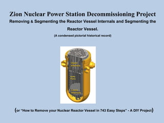
  • 1. Zion Nuclear Power Station Decommissioning Project Removing & Segmenting the Reactor Vessel Internals and Segmenting the Reactor Vessel. (A condensed pictorial historical record) (or “How to Remove your Nuclear Reactor Vessel in 743 Easy Steps” - A DIY Project)
  • 2. Presentation Notes and Disclaimers This presentation is NOT the work of any current Siempelkamp L.P., ZionSolutions or Energy Solutions employee and should in no way be associated with the image or reputation of any of these corporations. This is the effort of a single former employer of Siempelkamp who is proud of the work our teams accomplished and wanted to create a visual record of this work. The removal and segmentation of the various components of the Reactor Vessel Internals (RVI) and the segmentation of the Reactor Vessel (RVS) itself, was contracted out to Siempelkamp L.P. by ZionSolutions. Siempelkamp L.P. is an engineering and specialized equipment manufacturer based in Germany. This presentation provides a limited visual historical record of many of the activities of the Siempelkamp RV Segmentation Crew and some of the ZionSolutions Decommissioning Crew at the Zion Nuclear Power Station during the decommissioning work that occurred on-site from 2014 – 2015. A few of the images taken before 2014 are included to provide context for the RVI and RVS work. Most of the images shown were taken by members of the Siempelkamp Segmentation Crew and do not represent the entire scope of work that was performed during the removal and segmentation of the Reactor Vessel Internals (RVI) or the Reactor Vessel Segmentation (RVS) phase of the decommissioning work. Other images were collected from Internet sources and may be copyrighted. Please note that this presentation has been stripped down to fit into the 100MB limit (in this case, 37 pages) that Linked-In imposes for uploaded Presentations, so there are gaps in the processes as my original Presentation filled 97 pages. The 97 page Presentation is available for former Siempelkamp & Zion Solution crew members if they would like to contact me. After contact, you can mail a Flash drive to me or I can burn a CD with the entire 288MB file for you.
  • 3. The Zion Nuclear Power Station’s first unit began operation in December of 1973 and both PWR units were retired from operation on February 13, 1998. All nuclear fuel rods were removed from the reactor vessel and placed in the plant's on-site spent fuel pool by March 9, 1998. There were plans to keep the facility in long-term safe storage (SAFSTOR) until Unit 2's operating license expired on November 14, 2013. However, on August 23, 2010, it was announced that the Nuclear Regulatory Commission (NRC) had approved the transfer of Exelon's (ComEd's parent company) license to EnergySolutions of Salt Lake City. In 2011, ZionSolutions (a subsidiary of EnergySolutions) began decommissioning operations. Therefore, the residual radiation levels in and around the reactor vessel were allowed to decay for around 13 years which had a significant impact on reducing personnel radiation dosage rates during the Reactor Vessel Internals (RVI) and RV Segmentation (RVS) work. The original estimated date for decommissioning closure was December 31, 2026. Archive Image of the Zion Nuclear Power Station as viewed from a beach on Lake Michigan
  • 4. Finally breaking through the inside layer of concrete and rebar. Breaking through the concrete to another layer of rebar. One of the earlier major tasks for ZionSolutions was to cut a large equipment removal opening through the four foot thick Containment Building wall. The opening in Unit 1, with the sliding “Barn Doors” that were installed to restrict the spread of airborne contamination, is visible in the image above. (with the white doors partially opened) Also, you can see the several of the vertical green enclosures around the containment building tendons have been partially removed to provide access for the tendon removal. The tensioning had to be removed before an opening could safely be cut through that area of the containment wall and this will eventually be done for the entire structure. Breaking through to the first layer of rebar in Unit 2. Images of Zion Station During the Cutting of the Equipment Removal Opening in the Containment Buildings
  • 5. After removing the Reactor Head, the reactor internals were removed and placed in the reactor cavity. The reactor cavity had been flooded with borated water to provide shielding for the segmentation of the internals which was performed under water to reduce radiation exposure to the workers performing the RVI segmentation. The Reactor Vessel Internals were segmented into many smaller pieces that were then placed into the appropriate type of radwaste container for permanent disposal. The Reactor Vessel Segmentation plan had been to cut the RV into 3 sections, the Nozzle Level, which would be done first, the Belt-Line Level would be next and each of these levels would be further segmented around their circumference into 8 smaller segments as shown in some of the following images. The Hemispherical Bottom Head (HBH) would then be the last piece to be further segmented into 3 smaller segments; at least, that was the original plan. Upper and Lower RV Internals The Zion Station Reactor Vessel Upper Internals Nozzle Level Hemispherical Bottom Head (HBH) Belt-Line Level RV Segmentation Levels Removal of the Reactor Head and the Beginning of the RVI Phase
  • 6. The Volume Reduction Station (VRS) in the test pit facility at In-Place Machining in Milwaukee, Wisconsin The Volume Reduction Station (VRS) in the Mock-up area showing the 38i circular saw used to down-size reactor internal components for shipping. The Volume Reduction Station (VRS) is designed to segment the various components of the reactor vessel internals (Baffle Plates, Fuel Alignment Plate, Core Shroud, Core Barrel, etc) into pieces small enough to fit into the appropriate category of Radwaste liner (3-60B, 24PT4, etc). The horizontal reciprocating saw, used for making long cuts, is visible in the left image. After the RVI components had been segmented and packed in the appropriate Radwaste containers, they were shipped out by truck and train for long term burial at the Clive, Utah site and/or other sites. The spent fuel rods are stored at the Zion ISFSI in 61 containers along with 4 containers of Greater Than Class C (GTCC) waste collected during the reactor internals segmentation process and other decommissioning processes. The Zion Independent Spent Fuel Storage Installation (ISFSI) To date, I have been able to gather only these few images of the Reactor Vessel Internals (RVI) segmentation activities from our crew. If additional images are provided to me in the future, I can add them to this file. This is the end of the RVI portion of this presentation A GTCC waste container with Baffle Plates and other GTCC waste material cut to fit by the VRS.
  • 7. The Plan is to sequentially cut all 8 “L” shaped cuts through the Reactor Vessel Wall where the Pre-Cuts had been made through the thicker upper RV wall. After attaching the Turnable Gripper to the desired reactor segment, the final short horizontal cut is made between the two “L” cuts to free the segment. During the cutting of all 8 “L” cuts & Final Cuts the Suction Duct is removing the gases from the flame cutting and any airborne contamination to the HEPA filter. The Turnable Gripper (TGR), which is attached to the Polar Crane, then lifts the freed-up segment up through the opening in the Outer Shielding Plate (OSP) and places the segment in a Shielded Box for disposal as radwaste.
  • 8. Next, the Sand Box Covers needed to be removed to provide access to the area between the RV wall and the Bio-Shield. Hand-held plasma cutters were utilized to burn through the Sand Box cover welds so the covers could be removed Concrete blocks that provided additional shielding were removed from the Sand Boxes to provide access to the reactor coolant pipes so that they could be cut at the nozzles with a combination of wire saws and plasma cutters.
  • 9. Next, the concrete bridges that secured the top of the RV to the structure needed to be removed before the reactor coolant nozzle pipes could be cut. A jig was designed and fabricated to hold the concrete bridge in place during the cutting with the abrasive diamond wire saw until the concrete could be removed with a crane. A concrete bridge can be seen at the top of the above image. Installing the wire saw to cut each concrete bridge. Wire saw marks from the concrete bridge removal. The concrete bridges were placed in a Super Sack for disposal.
  • 10. With the concrete bridges now removed, the borated concrete around the outside of the RV was completely accessible to cut with the wire saw. The Polar Crane was then rigged to each borated concrete section for removal The borated concrete was cut on the centerline of each RV nozzle to free up each section for removal.
  • 11. The process of the initial vessel drain-down began by removing the Shielding Plate (SP) and replacing it with one half of the Inner Shielding Plate (ISP). This arrangement provided shielding for workers who installed the Tri-Nuc pump and drained the borated water down to a level below the vessel nozzles so that the cutting of the RV coolant loop pipes could commence. As the water was drained down in the RV, the nozzle openings were backwashed to flush as much radioactive sediment as possible out of the nozzle openings and into the bottom of the RV, where the remaining water provided some shielding during the remaining operations.
  • 12. Most of the circumference of each of the eight reactor coolant loop pipes is cut by the ABS from the bottom-up with the top “stitch” being cut with a hand-held plasma cutter. Installing the abrasive wire saw (ABS) to cut the bottom of the reactor coolant loop pipes The next step in the process was to start cutting the reactor coolant loop pipes.
  • 13. Here we have our team working at the peak of efficiency. The worker on the bottom is welding a shield plate into the RV nozzle to reduce radiation expose, while the worker in the middle is completing the loop cut using a hand-held plasma cutter. While in another area, the removal of the Seal Ledge continues. (you can see the remaining seal ledge has not been removed above the worker welding in the plugs.) Once all the reactor coolant loop pipes were removed, clearance checks were performed to assure the Flame Cutting System (FCS) could travel unobstructed around the circumference of the RV with adequate clearance from the nozzles.
  • 14. The initial vessel drain-down lowered the water level in the RV to less than a foot below the RV nozzle openings. The other half of the Inner Shielding Plate (ISP) was placed on the RV in preparation for the Final Drain-down. The Tri-Nuc pump was brought back into the reactor vessel and lowered to the bottom of the RV. The view looking down into the RV with the water drained. You can see the In-Core Instrumentation (ICI) conduit stubs in the bottom of the reactor vessel that remained full of water and will be drained later.
  • 15. The TSP Base Frame assembly was completed by installing the Vertical Shielding Plates and Liners and then the assembled frame was flown down with the Polar Crane and installed on top of the Reactor Vessel. Next, the Outer Shielding Plate (OSP) was assembled on the Support Platform. The OSP contains the Flame Cutting System mast assembly that drives the flame cutter and the Ventilation Flaps that cover the opening in the OSP from which the cut RV Segments will be removed. The Outer Shielding Plate (OSP) assembly was then installed on top of the TSP Base Frame on the Reactor Vessel and the electrical and gas line connections were completed. The Flame Cutting System (FCS) mast was installed vertically on the OSP. Installing the Turnable Shield Plate and the Flame Cutting System
  • 16. The mast will travel down outside the RV wall to burn the vertical cut and then travel horizontally along the track to complete the “L” shaped cuts in the RV. Making the final gas and electrical connections to the FCS Mast. The Flame Cutting System (FCS) Mast
  • 17. “Git er’Dun” OUTSTANDING WORK! Raising the LR up with the Chellino. Swinging the LR up and in with the Chellino. Connecting the LR to the Polar Crane. Doing the Coordinated Crane Dance with both cranes Doing the Coordinated Crane Dance with both cranes Bringing the Lifting Rod into Unit 1 with the Chellino & Polar Cranes
  • 18. Flying the Strand Jack System (SJS) bridge into position. Due to the weight hoisting limits and horizontal reach of the available cranes in the Containment Building (Polar Crane & Knuckle Boom Cranes) an engineered solution to raising the RV and moving the heavy RV segments (21 – 22 tons) had to be achieved. Since only the Polar Crane had the weight capacity to safely lift the RV segments that would be cut from the RV and the reach to place them in the shielded boxes, another method of lifting the entire RV had to be developed. The Siempelkamp engineered solution became known as the Strand Jack System (SJS) that included the Strand Jack Bridge. The bridge was placed across the center of the RV, then a set of 4 hydraulic jacks were attached to the bridge. Each of these four jacks were connected to the lifting rod by about 15 steel cables. The hydraulic jacks lifted the RV up to the various cutting levels, which freed up the Polar Crane to lift out each RV segment and place them in shielded boxes using the Turnable Gripper (TGR). The assembly of this system is shown in the next series of images. ABOUT THE STRAND JACK SYSTEM The Strand Jack System (SJS) bridge in position.
  • 19. The assembled Strand Jacks were moved into position with the Polar Crane and the Knuckle Boom Crane. Maneuvering the Strand Jacks into position on the SJS Bridge. Precise communication between the Polar Crane and the Knuckle Boom crane operators was crucial to safely installing the equipment. All 4 jacks were installed. As the RV is lifted, those strands sticking out of the top of the Jacks were managed with a loosely tied rope to keep the strands from splaying out.
  • 20. The Lifting Eyes are now ready to be attached to the LR so the RV can be raised to the first level cutting position with the Strand Jacks. The Lifting Eyes are now attached to the top of the LR.
  • 21. The Flame Cutting System performing the test cuts as viewed from a camera outside the RV. The flame cutting slag plume being blown into the RV as viewed from a camera inside the RV. The Flame Cutting System performing the test cuts as viewed from flame cutting head camera.The Flame Cutting System performing the test cuts as viewed from a camera outside the RV.
  • 22. The Flame Cutting System (FCS) performing the “L” cuts as viewed from a camera above the RV. The flame cutting blast plume as viewed from a camera inside the RV. The view from the cutting head camera after finishing the vertical part of the “L” cut. Monitoring the RV cutting process from the monitors inside the Control Station.
  • 23. And here comes the first segment now. It’s greeted by a standing room only crowd. A view of the Flame Cutting Head through the Gripper opening making the Final Cut to free a segment.
  • 24. These boxes in the shallow end are ready to receive the RV Nozzle segments. Other boxes have been positioned in the Deep End also. Once the first 4 boxes were filled they were moved out of the RV Cavity and 4 more empty boxes replaced these. Then the Polar Crane, with the Gripper attached, moves the RV segment across the RV cavity into a shielded box.
  • 25. Meanwhile, the ventilation system has been purging the flame cutting gases and any airborne contamination through the HEPA Filter. Then the OSP rotates to a position over the next segment to be cut on the opposite side from the first to attempt a balanced load. The TGR grabs the next segment and the Final Cut is again made. Then the Vent Flaps on the OSP are opened and the next segment is removed through the opening in the OSP. This process continued for all 8 segments. The view from inside the RV after the first RV segment was removed by the Gripper.
  • 26. Once filled, the shielded box covers were bolted back onto the box. The filled boxes were moved to the HLRS with the Polar Crane. “Going Up? The filled boxes waiting to be moved outside Unit 1 containment on the HLRS Cart.
  • 27. On this particularly windy day the boxes waited on the HLRS Cart until the wind died down the next day so they could be safely moved to the ground by the crane. The filled boxes get rolled out of the Unit 1 containment building on the HLRS. The filled boxes outside the Unit 1 containment building awaiting shipping. The filled boxes outside the containment building being moved off the HLRS by the Chellino crane.
  • 28. As the Nozzle boxes were being removed from containment, preparations for the Belt-Line cuts continued. The Strand Jacks raised the remaining reactor vessel up to the next cutting level. A Nuclear Safety Related (NSR) Sharpie was used to mark the cutting lines for the Belt-Line cuts. Maintenance was performed on the Flame Cutting System and the clearances were again checked. The sequential series of “L” shaped cuts was again performed and then the final cuts began.
  • 29. The first Belt-Line segment starting to come out past the vent flaps. Flying it up with the Gripper. Flying it up past the Strand Jacks on its way over to the Dance Floor. (Note the increased lengths of the strands exiting the top of each Strand Jack) Placing the Belt–Line segment in “The DownEnder”.
  • 30. Placing the first Belt-Line segment in the shielded box. (concave side up) The next Belt-Line segment was placed in the DownEnder. The second Belt-Line segment being laid horizontal. The second segment being moved into the same shielded box (concave side down) using the Aux. hook on the Polar Crane. Note that keeping the inside of the RV segments facing each other (concave to concave) reduces the overall radiation that the box has to shield against, thus reducing the box weight & cost.
  • 31. When the Lifting Adapter is installed on the top of the LR/HBH assembly, the Polar Crane main hook is attached to the Lifting Adapter. So now the load is on the Polar Crane’s main hook, which was previously needed to remove the RV segments. The Aux. hook on the Polar Crane is then rigged to the two HOT beams as seen above. The Aux. hook on the Polar Crane then moves the HOT beams off to each side. Note: you can see the SJS has been moved out of the way in the background of the above image. Now the Polar Crane lifts up the LR/HBH assembly with the main hook, up between the HOT beams, up past the SJS and over to the “Beach” where it will be welded to the HBH Stand.
  • 32. The Polar Crane moving the HBH over to the “Beach” where it will be welded to the HBH Stand.
  • 33. The HBH sitting on the HBH Stand with the corner posts welded to the stand. The crew welding the steel shielding cover onto the HBH in order to reduce radiation during transport.
  • 34. After the Siempelkamp crew caulks the circumference of the cover plate to make an airtight seal, they begin rigging to HBH to the Polar Crane All rigged and ready to go out of containment. Time for some pictures, we’re almost done.
  • 35. The last piece of the Unit 1 Reactor Vessel, the Hemispherical Bottom Head (HBH) being loaded on a flatbed truck and then wrapped for the long haul to its final burial site.
  • 36. On 12/16/2015, the 62.85 ton Unit 1 - Hemispherical Bottom Head (HBH) was shipped off the Zion site on this 34 wheeler flatbed truck to its final burial location. On 07/30/2015, the Unit 2 - Hemispherical Bottom Head (HBH) that weighed a little under 63 tons was shipped off the Zion site on this 34 wheeler flatbed truck to its final burial location.