SlideShare a Scribd company logo
1 of 70
Download to read offline
2
1
3
4
5
6
7
8
9
10
2
1
3
4
5
6
7
8
9
10
122
Applications All types of control system
Rated operational current le max AC-3 (Ue y 440 V) 9 A 12 A 18 A 25 A 32 A 38 A
le AC-1 (q y 60 °C) 20/25 A 25/32 A 25/40 A 50 A
Rated operational voltage 690 V on a and c
Number of poles 3 or 4 3 or 4 3 or 4 3 or 4 3
Rated operational power
in AC-3
220/240 V 2.2 kW 3 kW 4 kW 5.5 kW 7.5 kW 9 kW
380/400 V 4 kW 5.5 kW 7.5 kW 11 kW 15 kW 18.5 kW
415/440 V 4 kW 5.5 kW 9 kW 11 kW 15 kW 18.5 kW
500 V 5.5 kW 7.5 kW 10 kW 15 kW 18.5 kW 18.5 kW
660/690 V 5.5 kW 7.5 kW 10 kW 15 kW 18.5 kW 18.5 kW
1000 V – – – – – –
Auxiliary contacts 1 N/C and 1 N/O instantaneous incorporated in the contactors, with add-on blocks common to
the whole range comprising up to 4 N/C or N/O instantaneous, up to 1 N/O + 1 N/C time delay
and up to 2 N/O or 2 N/C protected contacts and 2 screen continuity terminals.
Thermal overload relays
manual-auto compatible
Class 10 A 0.10…10 A 0.10…13 A 0.10…18 A 0.10…32 A 0.10…38 A 0.10…38 A
Class 20 2.5…10 A 2.5…13 A 2.5…18 A 2.5…32 A
Suppressor modules
(c and low consumption
contactors are fitted with a
built-in bidirectional peak
limiting diode suppressior
as standard)
Varistor p p p p p p
Diode – – – – – –
RC circuit p p p p p p
Bidirectional peak
limiting diode
p p p p p p
Interfaces Relay output p p p p p p
Relay interface with
manual override switch
p p p p p p
Solid state p p p p p p
Contactor
type references
a or c 3 pole LC1 D09 LC1 D12 LC1 D18 LC1 D25 LC1 D32 LC1 D38
a 4 pole LC1 DT20/
LC1 D098
LC1 DT25/
LC1 D128
LC1 DT32/
LC1 D188
LC1 DT40/
LC1 D258
– –
c 4 pole – –
Reversing contactor
type references
a 3 pole LC2 D09 LC2 D12 LC2 D18 LC2 D25 LC2 D32 LC2 D38
c 3 pole LC2 D09 LC2 D12 LC2 D18 LC2 D25 LC2 D32 LC2 D38
a 4 pole LC2 DT20 LC2 DT25 LC2 DT32 LC2 DT40 – –
c 4 pole LC2 DT20 LC2 DT25 LC2 DT32 LC2 DT40 – –
Pages Contactors 152 to 157
Reversing contactors 162 to 165
Selection guide TeSys contactors
TeSys D contactors
2
1
3
4
5
6
7
8
9
10
2
1
3
4
5
6
7
8
9
10
123
40 A 50 A 65 A 80 A 95 A 115 A 150 A
60 A 80 A 125 A 200 A
690 V a or c 1000 V on a supply, 690 V on  c supply
3 4 3 3 4 3 4 3 3 4 3
11 kW 15 kW 18.5 kW 22 kW 25 kW 30 kW 40 kW
18.5 kW 22 kW 30 kW 37 kW 45 kW 55 kW 75 kW
22 kW 25/30 kW 30 kW 45 kW 45 kW 59 kW 80 kW
22 kW 30 kW 37 kW 55 kW 55 kW 75 kW 90 kW
30 kW 33 kW 37 kW 45 kW 45 kW 80 kW 100 kW
– – – 45 kW 45 kW 75 kW 90 kW
1 N/C and 1 N/O instantaneous incorporated in the contactors, with add-on blocks common to the whole range comprising up to 4 N/C or N/O instantaneous, up to
1 N/O + 1 N/C time delay and up to 2 N/O or 2 N/C protected contacts and 2 screen continuity terminals.
13…40 A 13…50 A 13…65 A 17…104 A 17…104 A 60…150 A 60…150 A
13…40 A 13…50 A 13…65 A 17…80 A 60…150 A 60…150 A
p p p p p p p p p p –
p p p p p p p p – – –
p p p p p p p p p p p
p p p p p p p p – – –
p p p p p p p p p p p
p p p p p p p p p p –
LC1 D40A LC1 D50A LC1 D65A LC1 D80 LC1 D95 LC1 D115 LC1 D150
LC1 DT60A – LC1 DT80A LC1 D80 – LC1 D115 –
LC2 D40A LC2 D50A LC2 D65A LC2 D80 LC2 D95 LC2 D115 LC2 D150
LC2 D40A LC2 D50A LC2 D65A – – – –
– – – LC2 D80 – LC2 D115 –
– – – – – – –
152 to 157
162 to 165
2
1
3
4
5
6
7
8
9
10
2
1
3
4
5
6
7
8
9
10
124
Applications Automation systems
Rated operational current le max AC-3 (Ue y 440 V) 9 A 12 A 18 A
le AC-1 (q y 60 °C) 20/25 A 20/25 A 25/32 A
Rated operational voltage 690 V
Number of poles 3 or 4 3 or 4 3 or 4
Rated operational
power in AC-3
220/240 V 2.2 kW 3 kW 4 kW
380/400 V 4 kW 5.5 kW 7.5 kW
415/440 V 4 kW 5.5 kW 9 kW
500 V 5.5 kW 7.5 kW 10 kW
660/690 V 5.5 kW 7.5 kW 10 kW
Coil consumption 2.4 W (100 mA - 24 V)
Operating ranges 0.7…1.25 Uc
Operating time
at 20 °C and at Uc
Closing 70 ms
Opening 25 ms
Auxiliary contact block modules 1 N/C and 1 N/O instantaneous contacts incorporated in the contactors, with add-on blocks
common to the whole range, comprising up to 2 N/C or 2 N/O instantaneous standard contacts
Interference suppression Built-in suppression as standard, by bi-directional peak limiting diode
Contactor type 3-pole LC1 D09 LC1 D12 LC1 D18
4-pole LC1 DT20/D098 LC1 DT25/D128 LC1 DT32/D188
Reversing contactor type 3-pole LC2 D09 LC2 D12 LC2 D18
4-pole LC2 DT20 LC2 DT25 LC2 DT32
Pages Contactors 152 to 157
Reversing contactors 162 to 165
(1)	With low consumption kit LA4 DBL (see page 173).
(2)	With 2 low consumption kits LA4 DBL (see page 173).
Selection guide TeSys contactors
TeSys D low consumption contactors
2
1
3
4
5
6
7
8
9
10
2
1
3
4
5
6
7
8
9
10
125
25 A 32 A 38 A 40 A 50 A 65 A
25/40 A 50 A 50 A 60 A – 80 A
690 V 690 V
3 or 4 3 3 3 3 3
5.5 kW 7.5 kW 9 kW 11 kW 15 kW 18.5 kW
11 kW 15 kW 18.5 kW 18.5 kW 22 kW 30 kW
11 kW 15 kW 18.5 kW 22 kW 25/30 kW 30 kW
15 kW 18.5 kW 18.5 kW 22 kW 30 kW 37 kW
15 kW 18.5 kW 18.5 kW 30 kW 33 kW 37 kW
2.4 W (100 mA - 24 V) 0.6 W (25 mA - 24 V) for relay LA4 DFB + the power consumed by the
contactor coil
0.7…1.25 Uc – – –
70 ms – – –
25 ms – – –
1 N/C and 1 N/O instantaneous contacts incorporated in the contactors, with add-on blocks common to the whole range, comprising up to 2 N/C or 2 N/O
instantaneous standard contacts
Built-in suppression as standard, by bi-directional peak limiting diode
LC1 D25 LC1 D32 LC1 D38 LC1 D40A (1) LC1 D50A (1) LC1 D65A (1)
LC1 DT40/D258 – – LC1 DT80A (1)
LC2 D25 LC2 D32 LC2 D38 LC2 D40A (2) LC2 D50A (2) LC2 D65A (2)
LC2 DT40
152 to 157
162 to 165
126
Selection� 5
Operational current and power conforming to IEC (q y 60 °C)
Contactor size LC1/
LP1
K06
LC1/
LP1
K09
LC1
K12
LC1
K16
LC1
D09
LC1
D12
LC1
D18
LC1
D25
LC1
D32
LC1
D38
LC1
D40A
Maximum operational current.
in AC-3
y 440 V A 6 9 12 16 9 12 18 25 32 38 40
Rated operational power P .
(standard motor power ratings)
220/240 V kW 1.5 2.2 3 3 2.2 3 4 5.5 7.5 9 11
380/400 V kW 2.2 4 5.5 7.5 4 5.5 7.5 11 15 18.5 18.5
415 V kW 2.2 4 5.5 7.5 4 5.5 9 11 15 18.5 22
440 V kW 3 4 5.5 7.5 4 5.5 9 11 15 18.5 22
500 V kW 3 4 4 5.5 5.5 7.5 10 15 18.5 18.5 22
660/690 V kW 3 4 4 4 5.5 7.5 10 15 18.5 18.5 30
1000 V kW – – – – – – – – – – –
Maximum operating rate in operating cycles/hour (1)
On-load factor Operational
power
LC1
D09
LC1
D12
LC1
D18
LC1
D25
LC1
D32
LC1
D38
LC1
D40A
y 85 % P – – – – 1200 1200 1200 1200 1000 1000 1000
0.5 P – – – – 3000 3000 2500 2500 2500 2500 2500
y 25 % P – – – – 1800 1800 1800 1800 1200 1200 1200
Operational current and power conforming to UL, CSA (q y 60 °C)
Contactor size LC1/
LP1
K06
LC1/
LP1
K09
LC1/
LP1
K12
LC1
D09
LC1
D12
LC1
D18
LC1
D25
LC1
D32
LC1
D38
LC1
D40A
Maximum operational current.
in AC-3
y 440 V A 6 9 12 9 12 18 25 32 – 40
Rated operational power P .
(standard motor power ratings .
60 Hz)
200/208 V HP 1.5 2 3 2 3 5 7.5 10 – 10
230/240 V HP 1.5 3 3 2 3 5 7.5 10 – 10
460/480 V HP 3 5 7.5 5 7.5 10 15 20 – 30
575/600 V HP 3 5 10 7.5 10 15 20 25 – 30
(1) Depending on the operational power and the on-load factor (q y 60 °C).
  
  
Characteristics :
pages 140 to 145
References :
pages 152 to 157
Dimensions, schemes :
pages 182 to 187
Characteristics :
pages 140 to 145
References :
pages 152 to 157
Dimensions, schemes :
pages 182 to 187
Characteristics :
pages 140 to 145
References :
pages 152 to 157
Dimensions, schemes :
pages 182 to 187
Characteristics :
pages 140 to 145
References :
pages 152 to 157
Dimensions, schemes :
pages 182 to 187
TeSys contactors� 5
For utilisation category AC-3
  
1
2
3
4
5
6
7
8
9
10
127
 5
LC1
D50A
LC1
D65A
LC1
D80
LC1
D95
LC1
D115
LC1
D150
LC1
F185
LC1
F225
LC1
F265
LC1
F330
LC1
F400
LC1
F500
LC1
F630
LC1
F780
LC1
F800
LC1
BL
LC1
BM
LC1
BP
LC1
BR
50 65 80 95 115 150 185 225 265 330 400 500 630 780 800 750 1000 1500 1800
15 18,5 22 25 30 40 55 63 75 100 110 147 200 220 250 220 280 425 500
22 30 37 45 55 75 90 110 132 160 200 250 335 400 450 400 500 750 900
25 30 45 45 59 80 100 110 140 180 220 280 375 425 450 425 530 800 900
30 30 45 45 59 80 100 110 140 200 250 295 400 425 450 450 560 800 900
30 37 55 55 75 90 110 129 160 200 257 355 400 450 450 500 600 750 900
33 37 45 45 80 100 110 129 160 220 280 335 450 475 475 560 670 750 900
.
.
– – 45 45 65 75 100 100 147 160 185 335 450 450 450 530 530 670 750
LC1
D50A
LC1
D65A
LC1
D80
LC1
D95
LC1
D115
LC1
D150
LC1
F185
LC1
F225
LC1
F265
LC1
F330
LC1
F400
LC1
F500
LC1
F630
LC1
F780
LC1
F800
LC1
BL
LC1
BM
LC1
BP
LC1
BR
1000 1000 750 750 750 750 750 750 750 750 500 500 500 500 500 120 120 120 120
2500 2500 2000 2000 2000 1200 2000 2000 2000 2000 1200 1200 1200 1200 600 120 120 120 120
.
.
1200 1200 1200 1200 1200 1200 1200 1200 1200 1200 1200 1200 1200 600 600 120 120 120 120
LC1
D50A
LC1
D65A
LC1
D80
LC1
D95
LC1
D115
LC1
D150
LC1
F185
LC1
F225
LC1
F265
LC1
F330
LC1
F400
LC1
F500
LC1
F630
LC1
F780
LC1
F800
50 65 80 95 115 150 185 225 265 330 400 500 630 780 800
15 20 30 30 30 40 50 60 60 75 100 150 250 – 350
15 20 30 30 40 50 60 75 75 100 125 200 300 450 400
40 40 60 60 75 100 125 150 150 200 250 400 600 900 900
.
.
40 50 60 60 100 125 150 150 200 250 300 500 800 – 900
 5
  
1
2
3
4
5
6
7
8
9
10
128
Selection (continued)� 5
Selection according to required electrical durability, in category AC-3 (Ue�  y 440 V)
Control of 3-phase asynchronous squirrel cage motors with breaking whilst running.
The current broken (Ic) in category AC-3 is equal to the rated operational current (Ie) of the motor.
Operational power in kW-50 Hz.
Example:
Asynchronous motor with  P = 5.5 kW - Ue = 400 V - Ie = 11 A - Ic = Ie = 11 A.
or asynchronous motor with  P = 5.5 kW - Ue = 415 V - Ie = 11 A - Ic = Ie = 11 A.
3 million operating cycles required. .
The above selection curves show the contactor rating needed: LC1 D18.
Selection according to required electrical durability, in category AC-3 (Ue = 660/690 V) (1)
Control of 3-phase asynchronous squirrel cage motors with breaking whilst running.
The current broken (Ic) in category AC-3 is equal to the rated operational current (Ie) of the motor.
(1)	For Ue = 1000 V, use the 660/690 V curves, but do not exceed the operational current at the operational power indicated for 1000 V.
2
1 3 4 5 6 7 8 9 10 12 16
18
20 30
25
32 40
37 50 65 80 115
95 150
0,5
0,6
0,8
1
1,5
2
4
6
8
10
LC1-D09
LC1,
LP1,
LP4
K09
LC1,
LP1,
LP4
K06
LC1
D12
LC1
K16
LC1,
LP1,
LP4
K12
LC1
D18
LC1
D25
LC1
D32
LC1
D38
LC1
D40A
LC1
D50A
LC1
D65A
LC1
D80
LC1
D95
LC1
D115
LC1
D150
200
0,55
0,75
1,5
2,2
3
4
5,5
7,5
11
15
18,5
22
25
30
230 V
400 V
0,75
1,5
2,2
4
5,5
7,5
11
15
18,5
22
30
37
kW
1,5
2,2
5,5
7,5
11
15
18,5
22
37
45
55
75
30
440 V kW
kW
45
55
75
Millions
of
operating
cycles
Current broken in A
2
1 3 4 5 6 7 8 9 10 12 16
18
20 30
25
32 40
37 50 65 80 115
95 150
0,5
0,6
0,8
1
1,5
2
4
6
8
10
LC1-D09
LC1,
LP1,
LP4
K09
LC1,
LP1,
LP4
K06
LC1
D12
LC1
K16
LC1,
LP1,
LP4
K12
LC1
D18
LC1
D25
LC1
D32
LC1
D38
LC1
D40A
LC1
D50A
LC1
D65A
LC1
D80
LC1
D95
LC1
D115
LC1
D150
200
0,55
0,75
1,5
2,2
3
4
5,5
7,5
11
15
18,5
22
25
30
230 V
400 V
0,75
1,5
2,2
4
5,5
7,5
11
15
18,5
22
30
37
kW
1,5
2,2
5,5
7,5
11
15
18,5
22
37
45
55
75
30
440 V kW
kW
45
55
75
Millions
of
operating
cycles
Current broken in A
0,6
0,8
1
1,5
2
3
4
6
8
10
LC1
D09
LC1
D12
LC1
D18
LC1
D25
LC1
D32,
LC1
D38
LC1
D40A
LC1
D50A
LC1
D65A
LC1
D80
LC1
D95
LC1
D115
LC1
D150
200
1 2 3 4 5 6 7 8
9
6,6
10
11
15
17
20
22 35
33 40
42 48
50 60 90
80 100
Millions
of
operating
cycles
Current broken in A
0,6
0,8
1
1,5
2
3
4
6
8
10
LC1
D09
LC1
D12
LC1
D18
LC1
D25
LC1
D32,
LC1
D38
LC1
D40A
LC1
D50A
LC1
D65A
LC1
D80
LC1
D95
LC1
D115
LC1
D150
200
1 2 3 4 5 6 7 8
9
6,6
10
11
15
17
20
22 35
33 40
42 48
50 60 90
80 100
Millions
of
operating
cycles
Current broken in A
Characteristics :
pages 140 to 145
References :
pages 152 to 157
Dimensions, schemes :
pages 182 to 187
Characteristics :
pages 140 to 145
References :
pages 152 to 157
Dimensions, schemes :
pages 182 to 187
Characteristics :
pages 140 to 145
References :
pages 152 to 157
Dimensions, schemes :
pages 182 to 187
Characteristics :
pages 140 to 145
References :
pages 152 to 157
Dimensions, schemes :
pages 182 to 187
TeSys contactors� 5
For utilisation category AC-3
1
2
3
4
5
6
7
8
9
10
129
Selection (continued)� 5
Selection according to required electrical durability, in category AC-3 (Ue�  y 440 V)
Control of 3-phase asynchronous squirrel cage motors with breaking whilst running.
The current broken (Ic) in category AC-3 is equal to the rated operational current (Ie) of the motor.
Operational power in kW-50 Hz.
Example:
Asynchronous motor with  P = 132 kW - Ue = 380 V - Ie = 245 A - Ic = Ie = 245 A
or asynchronous motor with  P = 132 kW - Ue = 415 V - Ie = 240 A - Ic = Ie = 240 A
1.5 million operating cycles required. 
The above selection curves show the contactor rating needed: LC1 F330.�	
(1)	The dotted lines are only applicable to LC1 BL contactors.
Selection according to required electrical durability, in category AC-3 (Ue = 660/690 V)
Control of 3-phase asynchronous squirrel cage motors with breaking whilst running.
The current broken (Ic) in category AC-3 is equal to the rated operational current (Ie) of the motor.
Example:
Asynchronous motor with P = 132 kW - Ue = 660 V - Ie = 140 A - Ic = Ie = 140 A
1.5 million operating cycles required.
The above selection curves show the contactor rating needed: LC1 F330.
(1)	The dotted lines are only applicable to LC1 BL contactors.
20 30 40 50 60 80
90
100 400 800 1000 2000
(1)
600
0,4
0,8
1
1,5
2
4
6
8
10
5,5
7,5
11
15
18,5
22
25
30
40
55
110
11
15
18,5
22
30
37
45
55
75
90
110
132
160
200
250
335
400
500
750
900
11
15
18,5
22
30
37
45
55
75
90
132
200
285
45
75
200
220
147
220 V
230 V
kW
kW
kW
380 V
400 V
440 V
LC1
F185
LC1
F225
LC1
F265
LC1
F330
LC1
F400
LC1
F500
LC1
F780
LC1
F630
LC1
F800
LC1
BP
LC1
BR
LC1
BL,
BM
0,6
200
Millions
of
operating
cycles
Current broken in A
0,6
0,8
1
1,5
2
4
6
8
10
20 30 40 50 60 80 90 100 400 800 1000 2000
200 600
118
129
170
220 305 355 485
LC1
F185
LC1
F225
LC1
F265
LC1
F330
LC1
F400
LC1
F500
LC1
F780
LC1
F800
LC1
F630
LC1
BP
LC1
BR
LC1
BL,
BM
0,4
kW
110
160
355
335
129
220
670
750
900
475
560
660 V
690 V
(1)
Millions
of
operating
cycles
Current broken in A
Characteristics :
pages 140 to 145
References :
pages 152 to 157
Dimensions, schemes :
pages 182 to 187
Characteristics :
pages 140 to 145
References :
pages 152 to 157
Dimensions, schemes :
pages 182 to 187
Characteristics :
pages 140 to 145
References :
pages 152 to 157
Dimensions, schemes :
pages 182 to 187
Characteristics :
pages 140 to 145
References :
pages 152 to 157
Dimensions, schemes :
pages 182 to 187
TeSys contactors� 5
For utilisation category AC-3
1
2
3
4
5
6
7
8
9
10
130
Selection� 5
Maximum operational current (open-mounted device)
Contactor size LC1/
LP1
K09
LC1/
LP1
K12
LC1
D09
LC1
DT20
LC1
D12
DT25
LC1
D18
DT32
LC1
D25
DT40
LC1
D32
LC1
D38
LC1
D40A
DT60A
Maximum operating rate .
in operating cycles/hour
600 600 600 600 600 600 600 600 600 600
Connection
conforming to IEC 60947-1
Cable c.s.a. mm2
4 4 4 4 4 6 6 10 10 35
Bar c.s.a. mm – – – – – – – – – –
Operational current in AC-1 in A,
according to the .
ambient temperature,.
conforming to IEC 60947-1
y 40 °C A 20 20 25 20 25 32 40 50 50 60
y 60 °C A 20 20 25 20 25 32 40 50 50 60
y 70 °C A (at UC) (1) (1) 17 (1) 17 22 28 35 35 42
Maximum operational.
power y 60 °C
220/230 V kW 8 8 9 8 9 11 14 18 18 21
240 V kW 8 8 9 8 9 12 15 19 19 23
380/400 V kW 14 14 15 14 15 20 25 31 31 37
415 V kW 14 14 17 14 17 21 27 34 34 41
440 V kW 15 15 18 15 18 23 29 36 36 43
500 V kW 17 17 20 17 20 23 33 41 41 49
660/690 V kW 22 22 27 22 27 34 43 54 54 65
1000 V kW – – – – – – – – – –
(1)	Please consult your Regional Sales Office.
Increase in operational current by parallel connection of poles
Apply the following coefficients to the currents or power values given above; these coefficients take into account an often unbalanced
current distribution between the poles:
2 poles in parallel: K = 1.6
3 poles in parallel: K = 2.25
4 poles in parallel: K = 2.8
b
b
b
Selection according to required electrical durability, in category AC-1 (Ue�  y 440 V)
Control of resistive circuits (cos φ u 0.95).
The current broken (Ic) in category AC-1 is equal to the current (Ie) normally drawn by the load.
Example:
Ue = 220 V - Ie = 50 A q y 40 °C - Ic�������������
 ������������
=�����������
 ����������
Ie��������
 �������
=������
 �����
50 A.
2 million operating cycles required.
The above selection curves show the contactor rating needed: either LC1 or LP1 D50.
b
b
b
    
20 25 32
10
2 4
3 6 8
1 40 50 60 80 100 125 200 400
0,1
0,2
0,4
0,6
0,8
1
1,5
2
4
6
8
10
LC1,
LP1,
LP4
K09
LC1,
LP1,
LP4
K12
LC1
D09
LC1
D12
LC1
D18
LC1
D25
LC1
D32,
LC1
D38
LC1
D40A
LC1
D50A
LC1
D65A
LC1,
LP1
D80
LC1
D95
LC1
D115
LC1
D150
250
Millions
of
operating
cycles
Current broken in A
20 25 32
10
2 4
3 6 8
1 40 50 60 80 100 125 200 400
0,1
0,2
0,4
0,6
0,8
1
1,5
2
4
6
8
10
LC1,
LP1,
LP4
K09
LC1,
LP1,
LP4
K12
LC1
D09
LC1
D12
LC1
D18
LC1
D25
LC1
D32,
LC1
D38
LC1
D40A
LC1
D50A
LC1
D65A
LC1,
LP1
D80
LC1
D95
LC1
D115
LC1
D150
250
Millions
of
operating
cycles
Current broken in A
Characteristics :
pages 140 to 145
Réferences :
pages 152 to 157
Dimensions, schemes :
pages 182 to 187
Characteristics :
pages 140 to 145
Réferences :
pages 152 to 157
Dimensions, schemes :
pages 182 to 187
Characteristics :
pages 140 to 145
Réferences :
pages 152 to 157
Dimensions, schemes :
pages 182 to 187
Characteristics :
pages 140 to 145
Réferences :
pages 152 to 157
Dimensions, schemes :
pages 182 to 187
TeSys contactors� 5
For utilisation category AC-1
    
1
2
3
4
5
6
7
8
9
10
131
 5
LC1
D50A
LC1
D65A
DT80A
LC1/
LP1
D80
LC1
D95
LC1
D115
LC1
D150
LC1
F185
LC1
F225
LC1
F265
LC1
F330
LC1
F400
LC1
F500
LC1
F630
LC1
F780
LC1
F800
LC1
BL
LC1
BM
LC1
BP
LC1
BR
600 600 600 600 600 600 600 600 600 600 600 600 600 600 600 120 120 120 120
35 35 50 50 120 120 150 185 185 240 – – – – – – – – –
– – – – – – – – – – 2
30 x 5
2
40 x 5
2
60 x 5
2
100 x 5
2
60 x 5
2
50 x 5
2
80 x 5
2
100 x 5
2
100 x 10
80 80 125 125 250 250 275 315 350 400 500 700 1000 1600 1000 800 1250 2000 2750
80 80 125 125 200 200 275 280 300 360 430 580 850 1350 850 700 1100 1750 2400
56 56 80 80 160 160 180 200 250 290 340 500 700 1100 700 600 900 1500 2000
29 29 45 45 80 80 90 100 120 145 170 240 350 550 350 300 425 700 1000
31 31 49 49 83 83 100 110 125 160 180 255 370 570 370 330 450 800 1100
50 50 78 78 135 135 165 175 210 250 300 430 600 950 600 500 800 1200 1600
54 54 85 85 140 140 170 185 220 260 310 445 630 1000 630 525 825 1250 1700
58 58 90 90 150 150 180 200 230 290 330 470 670 1050 670 550 850 1400 2000
65 65 102 102 170 170 200 220 270 320 380 660 750 1200 750 600 900 1500 2100
80 80 135 135 235 235 280 300 370 400 530 740 1000 1650 1000 800 1100 1900 2700
– – 120 120 345 345 410 450 540 640 760 950 1500 2400 1500 1100 1700 3000 4200
.
.
.
.
.
Example:
Ue = 220 V - Ie = 500 A - q y 40 °C - Ic = Ie = 500 A.
2 million operating cycles required.
The above selection curves show the contactor rating needed: LC1 F780.
(1)	The dotted lines are only applicable to LC1 F225 contactors.
b
b
b
    
20 40 50 60 80 100 200 300
400
600 800 1000 2000 4000
0,1
0,2
0,4
0,6
0,8
1
2
4
6
8
10
LC1
F185
LC1
F265
LC1
F225
LC1
F330
275 315
350
500 700
1600
LC1
F400
LC1
F500
LC1
F630
LC1
F800
LC1
F780
LC1
BL,
BM
LC1
BP
LC1
BR
(1)
Millions
of
operating
cycles
Current broken in A
20 40 50 60 80 100 200 300
400
600 800 1000 2000 4000
0,1
0,2
0,4
0,6
0,8
1
2
4
6
8
10
LC1
F185
LC1
F265
LC1
F225
LC1
F330
275 315
350
500 700
1600
LC1
F400
LC1
F500
LC1
F630
LC1
F800
LC1
F780
LC1
BL,
BM
LC1
BP
LC1
BR
(1)
Millions
of
operating
cycles
Current broken in A
 5
    
1
2
3
4
5
6
7
8
9
10
132
Selection� 5
Maximum breaking current
Category AC-2: slip ring motors - breaking the starting current.
Category AC-4: squirrel cage motors - breaking the starting current.
Contactor size LC1/
LP1
K06
LC1/
LP1
K09
LC1/
LP1
K12
LC1
D09
LC1
D12
LC1
D18
LC1
D25
LC1
D32
LC1
D38
LC1
D40A
In category AC-4 (le max) Ue y 440 V
le max broken = .
6 x l motor
A 36 54 54 54 72 108 150 192 192 240
440 V  Ue y 690 V
le max broken = .
6 x l motor
A 26 40 40 40 50 70 90 105 105 150
Depending on the maximum operating rate (1) and the on-load factor, q y 60 °C (2)
From 150 and 15 % to 300 and 10 % A 20 30 30 30 40 45 75 80 80 110
From 150 and 20 % to 600 and 10 % A 18 27 27 27 36 40 67 70 70 96
From 150 and 30 % to 1200 and 10 % A 16 24 24 24 30 35 56 60 60 80
From 150 and 55 % to 2400 and 10 % A 13 19 19 19 24 30 45 50 50 62
From 150 and 85 % to 3600 and 10 % A 10 16 16 16 21 25 40 45 45 53
(1)	Do not exceed the maximum number of operating cycles..
(2)	For temperatures higher than 60 °C, use a maximum operating rate value equal to 80% of the actual value when selecting from the tables.  
Counter current braking (plugging)
The current varies from the maximum plug-braking current to the rated motor current.
The making current must be compatible with the rated making and breaking capacities of the contactor.
As breaking normally takes place at a current value at or near the locked rotor current, the contactor can be selected using the criteria for
categories AC-2 and AC-4.
Permissible AC-4 power rating for 200 000 operating cycles
Operational voltage LCp/
LPp
K06
LCp/
LPp
K09
LCp
LPp
K12
LCp
D09
LCp
D12
LCp
D18
LCp
D25
LCp
D32
LCp
D38
LCp
D40A
220/230 V kW 0.75 1.1 1.1 1.5 1.5 2.2 3 4 4 4
380/400 V kW 1.5 2.2 2.2 2.2 3.7 4 5.5 7.5 7.5 9
415 V kW 1.5 2.2 2.2 2.2 3 3.7 5.5 7.5 7.5 9
440 V kW 1.5 2.2 2.2 2.2 3 3.7 5.5 7.5 7.5 11
500 V kW 2.2 3 3 3 4 5.5 7.5 9 9 11
660/690 V kW 3 4 4 4 5.5 7.5 10 11 11 15
  
  
TeSys contactors� 5
For utilisation categories AC-2 or AC-4
  
Characteristics :
pages 140 to 145
References :
pages 152 to 157
Dimensions, schemes :
pages 182 to 187
Characteristics :
pages 140 to 145
References :
pages 152 to 157
Dimensions, schemes :
pages 182 to 187
1
2
3
4
5
6
7
8
9
10
133
 5
.
.
LC1
D50A
LC1
D65A
LC1
D80
LC1
D95
LC1
D115
LC1
D150
LC1
F185
LC1
F225
LC1
F26
LC1
F330
LC1
F40
LC1
F500
LC1
F630
LC1
F780
LC1
F800
LC1
BL
LC1
BM
LC1
BP
LC1
BR
.
.
300 390 480 570 630 830 1020 1230 1470 1800 2220 2760 3360 4260 3690 4320 5000 7500 9000
.
.
170 210 250 250 540 640 708 810 1020 1410 1830 2130 2760 2910 2910 4000 4800 5400 6600
140 160 200 200 280 310 380 420 560 670 780 1100 1400 1600 1600 2250 3000 4500 5400
120 148 170 170 250 280 350 400 500 600 700 950 1250 1400 1400 2000 2400 3750 5000
100 132 145 145 215 240 300 330 400 500 600 750 950 1100 1100 1500 2000 3000 3600
80 110 120 120 150 170 240 270 320 390 450 600 720 820 820 1000 1500 2000 2500
70 90 100 100 125 145 170 190 230 290 350 500 660 710 710 750 1000 1500 1800
.
.
.
.
.
.
.
.
LCp
D50A
LCp
D65A
LCp
D80
LCp
D95
LC1
D115
LC1
D150
LC1
F185
LC1
F225
LC1
F265
LC1
F330
LC1
F400
LC1
F500
LC1
F630
LC1
F780
LC1
F800
LC1
BL
LC1
BM
LC1
BP
LC1
BR
5.5 7.5 7.5 9 9 11 18.5 22 28 33 40 45 55 63 63 90 110 150 200
11 11 15 15 18.5 22 33 40 51 59 75 80 100 110 110 160 160 220 250
11 11 15 15 18.5 22 37 45 55 63 80 90 100 110 110 160 160 250 280
11 15 15 15 18.5 22 37 45 59 63 80 100 110 132 132 160 200 250 315
15 15 22 22 30 37 45 55 63 75 90 110 132 150 150 180 200 250 355
15 18.5 25 25 30 45 63 75 90 110 129 140 160 185 185 200 250 315 450
 5
  
1
2
3
4
5
6
7
8
9
10
134
TeSys contactors� 5
For utilisation categories AC-2 or AC-4
Selection (continued)� 5
Selection according to required electrical durability, in categories AC-2 or AC-4 (Ue�  y 440 V)
Control of 3-phase asynchronous squirrel cage motors (AC-4) or slip ring motors (AC-2) with breaking whilst motor stalled.
The current broken (Ic) in AC-2 is equal to 2.5 x Ie.
The current broken (Ic) in AC-4 is equal to 6 x Ie. (Ie = rated operational current of the motor).
Example:
Asynchronous motor with P = 5.5 kW - Ue  = 400 V - Ie  = 11 A. Ic = 6 x Ie = 66 A
or asynchronous motor with P = 5.5 kW - Ue = 415 V - Ie = 11 A. Ic = 6 x Ie = 66 A.
200 000 operating cycles required.
The above selection curves show the contactor rating needed: LC1 D25. 
(1)	The dotted lines are only applicable to LC1, LP1 K12 contactors.
b
b
b
b
Selection according to required electrical durability, use in category AC-4 (440 V  Ue y 690 V)
Control of 3-phase asynchronous squirrel cage motors with breaking whilst motor stalled
The current broken (Ic) in AC-2 is equal to 2.5 x Ie.
The current broken (Ic) in AC-4 is equal to 6 x Ie. (Ie = rated operational current of the motor).
5 6 7 8 9 10 20 30 36 40 50 54 80
72 108 150 192 240 300 390 480 630 828 1000
570
0,01
0,02
0,03
0,04
0,06
0,05
0,08
0,1
0,2
0,4
0,6
0,8
1
LC1
D09
LC1
D12
LC1
D18
LC1
D25
LC1
D32
et
D38
LC1
D40A
LC1
D50A
LC1
D65A
LC1
D80
LC1
D95
LC1
D115
LC1
D150
LC1,
LP1,
LP4
K09,K12
LC1,
LP1,
LP4
K06
(1)
Millions
of
operating
cycles
Current broken in A
5 6 7 8 9 10 20 30 40 50 90
70 105 121 210 250 300 400 500 640 800 1000
540
0,01
0,02
0,03
0,04
0,06
0,05
0,08
0,07
0,1
0,2
0,4
0,6
0,8
1
LC1
D09
LC1
D12
LC1
D18
LC1
D25
LC1
D40A
LC1
D50A
LC1
D65A
LC1
D80
LC1
D95
LC1
D115
LC1
D150
150
LC1
D32,
D38
Millions
of
operating
cycles
Current broken in A
5 6 7 8 9 10 20 30 40 50 90
70 105 121 210 250 300 400 500 640 800 1000
540
0,01
0,02
0,03
0,04
0,06
0,05
0,08
0,07
0,1
0,2
0,4
0,6
0,8
1
LC1
D09
LC1
D12
LC1
D18
LC1
D25
LC1
D40A
LC1
D50A
LC1
D65A
LC1
D80
LC1
D95
LC1
D115
LC1
D150
150
LC1
D32,
D38
Millions
of
operating
cycles
Current broken in A
Characteristics :
pages 140 to 145
References :
pages 152 to 157
Dimensions, schemes :
pages 182 to 187
Characteristics :
pages 140 to 145
References :
pages 152 to 157
Dimensions, schemes :
pages 182 to 187
1
2
3
4
5
6
7
8
9
10
135
Selection (continued)� 5
Selection according to required electrical durability, in categories AC-2 or AC-4 (Ue�  y 440 V)
Control of 3-phase asynchronous squirrel cage motors (AC-4) or slip ring motors (AC-2) with breaking whilst motor stalled.
The current broken (Ic) in AC-4 is equal to 6 x Ie.
(Ie = rated operational current of the motor).
Example:
Asynchronous motor with P = 90 kW - Ue��������������������������������������������
 �������������������������������������������
= 380 V - Ie�������������������������������
 ������������������������������
= 170�������������������������
 ������������������������
A. Ic = 6 x Ie = 1020���
 ��
A .
or asynchronous motor with P = 90 kW - Ue = 415 V - Ie = 165 A. Ic = 6 x Ie = 990 A.
60 000 operating cycles required.
The above selection curves show the contactor rating needed: LC1 F265.
b
b
b
Selection according to required electrical durability, use in category AC-4 (440 V  Ue y 690 V)
Control of 3-phase asynchronous squirrel cage motors with breaking whilst motor stalled.
The current broken (Ic) in AC-4 is equal to 6 x Ie.
(Ie = rated operational current of the motor).
6000 10 000
100 200 400 600 800 1020 1470 2220 3360 4260
3690
2760
1230 1800
5000 8000 20 000
1
0,8
0,6
0,4
0,2
0,1
0,08
0,06
0,04
0,02
0,01
LC1
F185
LC1
F225
LC1
F265
LC1
F330
LC1
F400
LC1
F500
LC1
F630
LC1
F800
LC1
F780
LC1
BL,
BM
LC1
BP
LC1
BR
Millions
of
operating
cycles
Current broken in A
6000 10 000
100 200 400 600 800 1020 1470 2220 3360 4260
3690
2760
1230 1800
5000 8000 20 000
1
0,8
0,6
0,4
0,2
0,1
0,08
0,06
0,04
0,02
0,01
LC1
F185
LC1
F225
LC1
F265
LC1
F330
LC1
F400
LC1
F500
LC1
F630
LC1
F800
LC1
F780
LC1
BL,
BM
LC1
BP
LC1
BR
Millions
of
operating
cycles
Current broken in A
10 000
100 200 400 600 800 1000 2000 4000 8000 20 000
1
0,8
0,6
0,4
0,2
0,1
0,08
0,06
0,04
0,02
0,01
LC1
F185
LC1
F225
LC1
F265
LC1
F330
LC1
F400
LC1
F500
LC1
F630
LC1
F780,
F800
LC1
BL,
BM
LC1
BP
LC1
BR
Millions
of
operating
cycles
Current broken in A
10 000
100 200 400 600 800 1000 2000 4000 8000 20 000
1
0,8
0,6
0,4
0,2
0,1
0,08
0,06
0,04
0,02
0,01
LC1
F185
LC1
F225
LC1
F265
LC1
F330
LC1
F400
LC1
F500
LC1
F630
LC1
F780,
F800
LC1
BL,
BM
LC1
BP
LC1
BR
Millions
of
operating
cycles
Current broken in A
TeSys contactors� 5
For utilisation categories AC-2 or AC-4
Characteristics :
pages 140 to 145
References :
pages 152 to 157
Dimensions, schemes :
pages 182 to 187
Characteristics :
pages 140 to 145
References :
pages 152 to 157
Dimensions, schemes :
pages 182 to 187
1
2
3
4
5
6
7
8
9
10
136
Selection 5
+ –
2 poles
+ –
3 poles
+ –
4 poles
1 pole
+ –
Rated operational current (Ie) in Amperes, in utilisation category DC-1,
resistive loads: time constant
L
__
R
y 1 ms, ambient temperature y 60 °C
Rated
opera-
tional
voltage
Ue
No. of
poles
connec-
ted in
series
Contactor rating (1)
LC1
D09
LC1
DT20
LC1
D12
DT25
LC1
D18
DT32
LC1
D25
DT40
LC1
D32
LC1
D38
LC1
D40A
LC1
DT60A
V
24 1 20 20 20 25 32 40 40 50 50
2 20 20 20 25 32 40 40 50 50
3 20 20 20 25 32 40 40 50 50
4 – 20 20 25 32 – – – 50
48/75 1 20 20 20 25 32 40 40 50 50
2 20 20 20 25 32 40 40 50 50
3 20 20 20 25 32 40 40 50 50
4 – 20 20 25 32 – – – 50
125 1 4 4 4 4 7 7 7 7 7
2 20 20 20 25 32 40 40 50 50
3 20 20 20 25 32 40 40 50 50
4 – 20 20 25 32 – – – 50
250 1 1 1 1 1 1 1 1 1 1
2 4 4 4 4 7 7 7 7 7
3 20 20 20 25 32 40 40 50 50
4 – 20 20 25 32 – – – 50
300 3 4 4 4 4 7 7 7 7 –
4 – 20 20 25 32 – – – 50
460 1 – – – – – – – – –
4 – – – – – – – – –
900 2 – – – – – – – – –
1200 3 – – – – – – – – –
1500 4 – – – – – – – – –
Rated operational current (Ie) in Amperes, in utilisation category DC-2
to DC-5, inductive loads: time constant
L
__
R
y 15 ms, ambient temperature y 60 °C
Rated
oper-
ational
voltage
Ue
No. of
poles
connec-
ted in
series
C����������������
ontactor rating� (1)
LC1
D09
LC1
DT20
LC1
D12
DT25
LC1
D18
DT32
LC1
D25
DT40
LC1
D32
LC1
D38
LC1
D40A
LC1
DT60A
V
24 1 20 20 20 25 32 40 40 50 50
2 20 20 20 25 32 40 40 50 50
3 20 20 20 25 32 40 40 50 50
4 – 20 20 25 32 – – – 50
48/75 1 20 20 20 25 32 40 40 50 50
2 20 20 20 25 32 40 40 50 50
3 20 20 20 25 32 40 40 50 50
4 – 20 20 25 32 – – – 50
125 1 2 2 2 2 3 3 3 4 4
2 20 20 20 25 32 40 40 50 50
3 20 20 20 25 32 40 40 50 50
4 – 20 20 25 32 – – – 50
250 1 0,5 0,5 0,5 0,5 0,5 0,5 0,5 1 1
2 2 2 2 2 3 3 3 4 4
3 8 8 8 8 32 40 40 50 50
4 – 20 20 25 32 – – – 50
300 3 2 2 2 2 3 3 3 3 3
4 – 8 8 8 32 – – – 50
460 1 – – – – – – – – –
4 – – – – – – – – –
900 2 – – – – – – – – –
1200 3 – – – – – – – – –
1500 4 – – – – – – – – –
(1)	For rated operational currents of contactors LC1 and LP1 K: please consult your
Regional Sales Office.
    
TeSys contactors 5
For utilisation categories DC-1 to DC-5
       
Characteristics:
pages 140 to 145
References:
pages 152 to 157
Dimensions, schemes:
pages 182 to 187
Characteristics:
pages 140 to 145
References:
pages 152 to 157
Dimensions, schemes:
pages 182 to 187
137
 5
 5
      
LC1
D50A
LC1
D65A
LC1
DT80A
LC1
D80
LC1
D95
LC1
D115
LC1
D150
LC1
F185
LC1
F225
LC1
F265
LC1
F330
LC1
F400
LC1
F500
LC1
F630
LC1
F780
LC1
F800
LC1
BL
LC1
BM
LC1
BP
LC1
BR
65 65 65 100 100 200 200 240 260 300 360 430 580 850 1300 850 700 1100 1750 2400
65 65 65 100 100 200 200 240 260 300 360 430 580 850 1300 850 700 1100 1750 2400
65 65 65 100 100 200 200 240 260 300 360 430 580 850 1300 850 700 1100 1750 2400
– – 65 100 – 200 – 240 260 300 360 430 580 850 1300 850 700 1100 1750 2400
65 65 65 100 100 200 200 240 260 300 360 430 580 850 1300 850 700 1100 1750 2400
65 65 65 100 100 200 200 240 260 300 360 430 580 850 1300 850 700 1100 1750 2400
65 65 65 100 100 200 200 240 260 300 360 430 580 850 1300 850 700 1100 1750 2400
– – 65 100 – 200 – 240 260 300 360 430 580 850 1300 850 700 1100 1750 2400
7 7 7 12 12 12 12 210 230 270 320 380 520 760 1180 760 700 1100 1750 2400
65 65 65 100 100 200 200 210 230 270 320 380 520 760 1180 760 700 1100 1750 2400
65 65 65 100 100 200 200 240 260 300 360 430 580 850 1300 850 700 1100 1750 2400
– – 65 100 – 200 – 240 260 300 360 430 580 850 1300 850 700 1100 1750 2400
1 1,5 1,5 2 2 10 10 – – – – – – – – – 700 1100 1750 2400
7 7 7 12 12 200 200 190 200 250 280 350 450 700 1000 700 700 1100 1750 2400
65 65 65 100 100 200 200 240 260 300 360 430 580 850 1300 850 700 1100 1750 2400
– – 65 100 – 200 – 240 260 300 360 430 580 850 1300 850 700 1100 1750 2400
7 7 7 12 12 200 200 190 200 250 280 350 450 700 1000 700 700 1100 1750 2400
– – 65 100 – 200 – 240 260 300 360 430 580 850 1000 850 700 1100 1750 2400
– – – – – – – – – – – – – – – – 700 1100 1750 2400
– – – – – 200 – 190 200 250 280 350 450 700 1000 700 700 1100 1750 2400
– – – – – – – – – – – – – – – – 700 1100 1750 2400
– – – – – – – – – – – – – – – – 700 1100 1750 2400
– – – – – – – – – – – – – – – – 700 1100 1750 2400
LC1
D50A
LC1
D65A
LC1
DT80A
LC1
D80
LC1
D95
LC1
D115
LC1
D150
LC1
F185
LC1
F225
LC1
F265
LC1
F330
LC1
F400
LC1
F500
LC1
F630
LC1
F780
LC1
F800
LC1
BL
LC1
BM
LC1
BP
LC1
BR
65 65 65 100 100 200 200 240 260 300 360 430 580 850 1300 850 700 1100 1750 2400
65 65 65 100 100 200 200 240 260 300 360 430 580 850 1300 850 700 1100 1750 2400
65 65 65 100 100 200 200 240 260 300 360 430 580 850 1300 850 700 1100 1750 2400
– – 65 100 – 200 – 240 260 300 360 430 580 850 1300 850 700 1100 1750 2400
65 65 65 100 100 200 200 240 260 300 360 430 580 850 1300 850 700 1100 1750 2400
65 65 65 100 100 200 200 240 260 300 360 430 580 850 1300 850 – – – –
65 65 65 100 100 200 200 240 260 300 360 430 580 850 1300 850 700 1100 1750 2400
– – 65 100 – 200 – 240 260 300 360 430 580 850 1300 850 700 1100 1750 2400
4 4 4 5 5 10 10 – – – – – – – – – 700 1100 1750 2400
65 65 65 100 100 200 200 160 180 250 300 350 500 700 1000 700 700 1100 1750 2400
65 65 65 100 100 200 200 240 240 280 310 350 550 850 1000 850 700 1100 1750 2400
– – 65 100 – 200 – 240 240 280 310 350 550 850 1000 850 700 1100 1750 2400
1 1.5 1.5 1 1 3 3 – – – – – – – – – 700 1100 1750 2400
4 4 4 5 5 200 200 140 160 220 280 310 480 680 900 680 700 1100 1750 2400
65 65 65 100 100 200 200 160 180 250 300 350 500 700 1000 700 700 1100 1750 2400
– – 65 100 – 200 – 240 260 300 360 430 580 850 1300 850 700 1100 1750 2400
3 3 3 5 5 200 200 140 160 220 280 310 480 680 900 680 700 1100 1750 2400
– – 65 100 – 200 – 240 260 300 360 430 580 850 1300 850 700 1100 1750 2400
– – – – – – – – – – – – – – – – 700 1100 1750 2400
– – – – – 200 – 140 160 220 280 310 480 680 800 680 700 1100 1750 2400
– – – – – – – – – – – – – – – – 700 1100 1750 2400
– – – – – – – – – – – – – – – – 700 1100 1750 2400
– – – – – – – – – – – – – – – – 700 1100 1750 2400
    
Characteristics:
pages 140 to 145
References:
pages 152 to 157
Dimensions, schemes:
pages 182 to 187
Characteristics:
pages 140 to 145
References:
pages 152 to 157
Dimensions, schemes:
pages 182 to 187
138
Selection� 5
Selection according to required electrical durability, use in categories DC-1 to DC-5
The criteria for contactor selection are:
the rated operational current Ie,
the rated operational voltage Ue,
the utilisation category and the time constant L/R,
the required electrical durability.
b
b
b
b
Maximum operating rate (operating cycles)
The following limits must not be exceeded: 120 operating cycles/hour at rated operational current Ie.
Electrical durability
Example
Series wound motor - P = 1.5 kW - Ue = 200 V - Ie = 7.5 A. Utilisation: reversing, inching.
Utilisation category = DC-5.
Select contactor LC1 D09 with 3 poles in series.
The power broken is: Pc total = 2.5 x 200 x 7.5 = 3.75 kW.
The power broken per pole is: 1.25 kW.
The electrical durability read from the curve is u 3 millions of operating cycles.
b
b
b
b
b
Use of poles in parallel
Electrical durability can be increased by using poles connected in parallel.
With N poles connected in parallel, the electrical durability becomes: electrical
durability read from the curves x N x 0.7.
Note: 1
When the poles are connected in parallel, the maximum operational currents
indicated on pages 136 et 137 must not be exceeded.
Note: 2
Ensure that the connections are made in such a way as to equalise the currents in
each pole.
0,01
0,02
0,04
0,06
0,08
1
2
4
6
8
10
0,1
0,2
0,4
0,6
0,8
0,2 0,3 0,4 0,5 0,6
0,7
1
0,8
0,9
2 3 4 5 6 7 9
8 10 16
14 20 30
24 32 36
40 50 60 70 90
80
100
LC1
D09
LC1
D12
LC1
D18
LC1
D25
LC1
D32,
LC1
D38
LC1
D40A,
DT60A
LC1
D50A
LC1
D65A,
DT80A
LC1,
LP1
D80
LC1
D95
LC1
D115,
D150
Millions
of
operating
cycles
Power broken per pole in kW
Characteristics:
pages 140 to 145
References:
pages 152 to 157
Dimensions, schemes:
pages 182 to 187
Characteristics:
pages 140 to 145
References:
pages 152 to 157
Dimensions, schemes:
pages 182 to 187
Characteristics:
pages 140 to 145
References:
pages 152 to 157
Dimensions, schemes:
pages 182 to 187
Characteristics:
pages 140 to 145
References:
pages 152 to 157
Dimensions, schemes:
pages 182 to 187
TeSys contactors� 5
For utilisation categories DC-1 to DC-5
139
Selection (continued)� 5
Selection according to required electrical durability, use in categories DC-1 to DC-5
Determining the electrical durability
The electrical durability can be read directly from the curves below, having previously calculated the power broken as follows: .
P broken = U broken x l broken..
The tables below give the values of Uc and Ic for the various utilisation categories.
Power broken
Utilisation categories U broken I broken P broken
DC-1   Non inductive or slightly inductive loads Ue Ie Ue x Ie
DC-2   Shunt wound motors, breaking whilst motor running 0.1 Ue Ie 0.1 Ue x Ie
DC-3   Shunt wound motors, reversing, inching Ue 2.5 Ie Ue x 2.5 Ie
DC-4   Series wound motors, breaking whilst motor running 0.3 Ue Ie 0.3 Ue x Ie
DC-5   Series wound motors, reversing, inching Ue 2.5 Ie Ue x 2.5 Ie
Example
Series wound motor: P = 40 kW - Ue = 200 V - Ie = 200 A. Utilisation: reversing, inching.
Utilisation category = DC-5.
Select contactor LC1 F265 with 2 poles in series.
The power broken is: Pc total = 2.5 x 200 x 200 = 100 kW.
The power broken per pole is 50 kW.
The electrical durability read from the curve is 500 000 operating cycles.
b
b
b
b
2 3 4 5 6 7 9
10
20 30 40 50 60 70
100
90 200 300 400
500
600
700
1000
800
900 2000
4000
3000 5000
LC1
F185,
F225
LC1
F265
LC1
F330
LC1
F400
LC1
F500
LC1
F630,
F800
LC1
F780
LC1
BL,
BM
LC1
BP
LC1
BR
0,01
0,02
0,04
0,06
0,08
1
2
4
6
8
10
0,1
0,2
0,4
0,6
0,8
Millions
of
operating
cycles
Power broken per pole in kW
Characteristics:
pages 140 to 145
References:
pages 152 to 157
Dimensions, schemes:
pages 182 to 187
Characteristics:
pages 140 to 145
References:
pages 152 to 157
Dimensions, schemes:
pages 182 to 187
Characteristics:
pages 140 to 145
References:
pages 152 to 157
Dimensions, schemes:
pages 182 to 187
Characteristics:
pages 140 to 145
References:
pages 152 to 157
Dimensions, schemes:
pages 182 to 187
TeSys contactors� 5
For utilisation categories DC-1 to DC-5
140
Contactor type LC1 D09…D18
DT20 and
DT25
D25…D38
DT32 and
DT40
D40A…D65A
DT60A and
DT80A
D80…D95 D115 and
D150
Environment
Rated insulation voltage (Ui) Conforming to IEC 60947-4-1,
overvoltage category III, .
degree of pollution: 3
V 690 1000
Conforming to UL, CSA V 600
Rated impulse
withstand voltage (Uimp)
Conforming to IEC 60947 kV 6 8
Conforming to standards IEC/EN 60947-4-1, IEC/EN 60947-5-1, UL 508, CSA C22.2 n°14.
Product certifications UL, CSA (1), CCC, GOST
GL, DNV, RINA, BV, LROS (pending for contactors LC1 D40A to D65A)
Degree of protection (2)
(front face only)
Conforming to VDE 0106 .
and IEC 60529
Power circuit connections Protection against direct finger contact IP 2X
Coil connection Protection against direct finger contact IP 2X
Protective treatment Conforming to IEC 60068-2-30 “TH”
Ambient air temperature
around the device
Storage °C - 60…+ 80
Operation °C - 5…+ 60
Permissible °C - 40…+ 70, for operation at Uc
Maximum operating altitude Without derating m 3000
Operating positions
(3)
Without derating .
in the following positions
a/c a c
9
0
°
90 °
180
°
180
°
Positions that are .
not permissible
For c contactors LC1 D09 to LC1 D65A.
Flame resistance Conforming to UL 94 V1
Conforming to IEC 60695-2-1 °C 850
Shock resistance (4)
1/2 sine wave = 11 ms
Contactor open 10 gn 8 gn 10 gn 8 gn 6 gn
Contactor closed 15 gn 15 gn 15 gn 10 gn 15 gn
Vibration resistance (4)
5…300 Hz
Contactor open 2 gn
Contactor closed 4 gn 4 gn 4 gn 3 gn 4 gn
(1)	Contactor LC1 D95 with d.c. coil is not UL/CSA certified.
(2)	Protection provided for the cabling c.s.a.'s indicated on the next page and for connection by cable.
(3)	When mounting on a vertical rail, use a stop.
(4)	Without modifying the contact states, in the most unfavourable direction (coil energised at Ue).
Characteristics TeSys contactors
TeSys D contactors
141
Contactor type LC1 D09
and D12
DT20
and DT25
D18
(3P)
D25
(3P)
D32 D38 D18 and
D25 (4P)
DT32 and
DT40
D40A to
D65A
DT60A
and
DT80A (1)
D80
and D95
D115
and D150
Power circuit connections
Screw clamp terminal connections
Tightening Screw clamp terminals Connector
2 inputs
Screw
clamp
terminals
Connector
1 input
Connector
2 inputs
Flexible cable
without cable end
1 conductor mm2
1…4 1.5…6 2.5…10 2.5…10 1…35 4…50 10…120
2 conductors mm2
1…4 1.5…6 2.5…10 2.5…10 1…25
and 1…35
4…25 10…120
+ 10…50
Flexible cable
with cable end
1 conductor mm2
1…4 1…6 1…10 2.5…10 1…35 4…50 10…120
2 conductors mm2
1…2.5 1…4 1.5…6 2.5…10 1…25
and 1…35
4…16 10…120
+ 10…50
Solid cable
without cable end
1 conductor mm2
1…4 1.5…6 1.5…10 2.5…16 1…35 4…50 10…120
2 conductors mm2
1…4 1.5…6 2.5…10 2.5…16 1…25
and 1…35
4…25 10…120
+ 10…50
Screwdriver Philips N° 2 N° 2 N° 2 N° 2 – – –
Flat screwdriver Ø Ø 6 Ø 6 Ø 6 Ø 6 – Ø 6…Ø 8 –
Hexagonal key – – – – 4 4 4
Tightening torque N.m 1.7 1.7 2.5 1.8 5:
y 25 mm2
8: 35 mm2
9 12
Spring terminal connections (2)
Flexible cable
without cable end
1 conductor mm2
2.5
(4: DT25)
4 4 4 – 10 – –
2 conductors mm2
2.5
(except
DT25)
4 4 4 – – – –
Connection by bars or lugs
Bar c.s.a. – – – – – – 3 x 16 5 x 25
Lug external Ø mm 8 8 10 10 8 16.5 17 25
Ø of screw mm M3.5 M3.5 M4 M4 M3.5 M6 M6 M8
Screwdriver Philips N° 2 N° 2 N° 2 N° 2 N° 2 – – –
Flat screwdriver Ø Ø 6 Ø 6 Ø 6 Ø 6 Ø 6 – Ø 8 –
Key for hexagonal headed screw – – – – – 10 10 13
Tightening torque N.m 1.7 1.7 2.5 2.5 1.8 6 9 12
Control circuit connections
Connection by cable (tightening via screw clamps)
Flexible cable
without cable end
1 conductor mm2
1…4 1…4 1…4 1…4 1…4 1…4 1…4 1…2.5
2 conductors mm2
1…4 1…4 1…4 1…4 1…4 1…4 1…4 1…2.5
Flexible cable
with cable end
1 conductor mm2
1…4 1…4 1…4 1…4 1…4 1…4 1…2.5 1…2.5
2 conductors mm2
1…2.5 1…2.5 1…2.5 1…2.5 1…2.5 1…2.5 1…2.5 1…2.5
Solid cable
without cable end
1 conductor mm2
1…4 1…4 1…4 1…4 1…4 1…4 1…4 1…2.5
2 conductors mm2
1…4 1…4 1…4 1…4 1…4 1…4 1…4 1…2.5
Screwdriver Philips N° 2 N° 2 N° 2 N° 2 N° 2 N° 2 N° 2 N° 2
Flat screwdriver Ø Ø 6 Ø 6 Ø 6 Ø 6 Ø 6 Ø 6 Ø 6 Ø 6
Tightening torque N.m 1.7 1.7 1.7 1.7 1.7 1.7 1.2 1.2
Spring terminal connections (2)
Flexible cable
without cable end
1 conductor mm2
2.5 2.5 2.5 2.5 – 2.5 0.75…2.5 – –
2 conductors mm2
2.5 2.5 2.5 2.5 – 2.5 0.75…2.5 – –
Connection by bars or lugs
Lug external Ø mm 8 8 8 8 8 8 8 8
Ø of screw mm M3.5 M3.5 M3.5 M3.5 M3.5 M3.5 M3.5 M3.5
Screwdriver Philips N° 2 N° 2 N° 2 N° 2 N° 2 N° 2 N° 2 N° 2
Flat screwdriver Ø Ø 6 Ø 6 Ø 6 Ø 6 Ø 6 Ø 6 Ø 6 Ø 6
Tightening torque N.m 1.7 1.7 1.7 1.7 1.7 1.7 1.2 1.2
(1)	BTR screws: hexagon socket head. In accordance with local electrical wiring regulations, a size 4 insulated Allen key must be used (reference LAD ALLEN4,
see page 175).
(2)	If cable ends are used, choose the next size down (example: for 2.5 mm2
, use 1.5 mm2
) and square crimp the cable ends using a special tool.
Characteristics (continued) TeSys contactors
TeSys D contactors
142
Contactor type LC1 D09
(3P)
DT20
D098
D12
(3P)
DT25
D128
D18
(3P)
DT32
D188
D25
(3P)
DT40
D258
Pole characteristics
Rated operational current (Ie)
(Ue y 440 V)
In AC-3, q y 60 °C A 9 12 18 25
In AC-1, q y 60 °C A 25 (1) 20 25 (1) 25 32 (1) 32 40 (1) 40
Rated operational voltage (Ue) Up to V 690 690 690 690
Frequency limits Of the operational current Hz 25…400 25…400 25…400 25…400
Conventional thermal
current (Ith)
q y 60 °C A 25 (1) 20 25 (1) 25 32 (1) 32 40 (1) 40
Rated making capacity (440 V) Conforming to IEC 60947 A 250 250 300 450
Rated breaking capacity (440 V) Conforming to IEC 60947 A 250 250 300 450
Permissible short time rating
No current flowing for preceding
15 minutes with  q y 40 °C
For 1 s A 210 210 240 380
For 10 s A 105 105 145 240
For 1 min A 61 61 84 120
For 10 min A 30 30 40 50
Fuse protection
against short-circuits .
(U y 690 V)
Without thermal
overload relay, .
gG fuse
type 1 A 25 40 50 63 
type 2 A 20 25 35 40
With thermal overload relay A See pages 208 to 211, for aM or gG fuse ratings corresponding to the associated
thermal overload relay
Average impedance per pole At Ith and 50 Hz mW 2.5 2.5 2.5 2
Power dissipation per pole for
the above operational currents
AC-3 W 0.20 0.36 0.8 1.25
AC-1 W 1.56 1.56 2.5 3.2
Control circuit characteristics, a.c. supply
Rated control circuit voltage (Uc) 50/60 Hz V 12…690
Control voltage limits
50 or 60 Hz coils Operation –
Drop-out –
50/60 Hz coils Operation 0.8…1.1 Uc on 50 Hz and 0.85…1.1 Uc on 60 Hz at 60 °C
Drop-out 0.3…0.6 Uc at 60 °C
Average consumption
at 20 °C and at Uc
a 50 Hz Inrush 50 Hz coil VA –
Cos j 0.75
50/60 Hz coil VA 70
Sealed 50 Hz coil VA –
Cos j 0.3
50/60 Hz coil VA 7
a 60 Hz Inrush 60 Hz coil VA –
Cos j 0.75
50/60 Hz coil VA 70
Sealed 60 Hz coil VA –
Cos j 0.3
50/60 Hz coil VA 7.5
Heat dissipation 50/60 Hz W 2…3
Operating time
(2)
Closing C ms 12…22
Opening O ms 4…19
Mechanical durability
in millions of operating cycles
50 or 60 Hz coil –
50/60 Hz coil on 50 Hz 15
Maximum operating rate
at ambient temperature y 60 °C
In operating cycles per hour 3600
(1)	Versions with spring terminal connections:
16 A for LC1 D093 and LC1 D123 (20 A possible with 2 x 2.5 mm2
in parallel),
25 A for LC1 D183 to LC1 D323 (32 A possible for LC1 D183 connected with 2 x 4 mm2
cables in parallel; 40 A possible for LC1 D253 and LC1 D323 connected
with 2 x 4 mm2
in parallel).
(2) The closing time C is measured from the moment the coil supply is switched on to closure of the main poles. The opening time O is measured from the
moment the coil supply is switched off to the moment the main poles separate.
Characteristics (continued) TeSys contactors
TeSys D contactors
Selection :
pages 126 to 257
References:
pages 152 to 157
Dimensions:
pages 182 to 185
Schemes:
pages 186 and 187
143
D32 D38 D40A DT60A D50A D65A DT80A D80 D95 D115 D150
32 38 40 – 50 65 – 80 95 115 150
50 (1) 50 60 60 80 80 80 125 125 200 200
690 690 690 690 690 690 690 1000 1000 1000 1000
25…400 25…400 25…400 25…400 25…400 25…400 25…400 25…400 25…400 25…400 25…400
50 50 60 60 80 80 80 125 125 200 200
550 550 800 800 900 1000 1000 1100 1100 1260 1660
550 550 800 800 900 1000 1000 1100 1100 1100 1400
430 430 720 720 810 900 900 990 1100 1100 1400
260 310 320 320 400 520 520 640 800 950 1200
138 150 165 165 208 260 260 320 400 550 580
60 60 72 72 84 110 110 135 135 250 250
63 63 80 80 100 125 125 200 200 250 315
63. 63 80 80 100 125 125 160 160 200 250
See pages 208 to 211 for aM or gG fuse ratings corresponding to the associated thermal overload relay
2 2 1.5 1.6 1.5 1.5 1.6 0.8 0.8 0.6 0.6
2 3 2.4 – 3.7 6.3 – 5.1 7.2 7.9 13.5
5 5 5.4 5.8 9.6 9.6 10.2 12.5 12.5 24 24
12…690 12…690 24…500
– – 0.85…1.1 Uc at 55 °C
– – 0.3…0.6 Uc at 55 °C 0.3…0.5 Uc at 55 °C
0.8…1.1 Uc on 50 Hz and.
0.85…1.1 Uc on 60 Hz .
at 60 °C
0.8…1.1 Uc on 50 Hz and
0.85…1.1 Uc on 60 Hz at 60 °C
0.8…1.1 Uc on 50 Hz and
0.85…1.1 Uc on 60 Hz .
at 55 °C
0.8…1.15 Uc on 50/60 Hz
at 55 °C
0.3…0.6 Uc at 60 °C 0.3…0.6 Uc at 60 °C 0.3…0.6 Uc at 55 °C 0.3…0.5 Uc at 55 °C
– – 200 300 –
0.75 0.75 0.75 0.8 0.9
70 160 245 280…350 280…350
– – 20 22 –
0.3 0.3 0.3 0.3 0.9
7 15 26 2…18 2…18
– – 220 300 –
0.75 0.75 0.75 0.8 0.9
70 140 245 280…350 280…350
– – 22 22 –
0.3 0.3 0.3 0.3 0.9
7.5 13 26 2…18 2…18
2…3 4…5 6…10 3…8 3…4.5
12…22 12…26 12…26 12…26 12…26 12…26 20…35 20…35 20…50 20…35
4…19 4…19 4…19 4…19 4…19 4…19 6…20 6…20 6…20 40…75
– – – – – – 10 10 8 –
15 6 6 6 6 6 4 4 8 8
3600 3600 3600 3600 3600 3600 3600 3600 2400 1200
144
Contactor type LC1 D09…D38
LC1 DT20…DT40
LC1D40A…D65A
LC1DT60andDT80
LC1 or LP1 D80
LC1 D95
LC1 D115 and
LC1 D150
d.c. control circuit characteristics
Rated control circuit��������
�������
voltage
(Uc)
c V 12…440 12…440 24…440
Rated insulation voltage Conforming to IEC 60947-1 V 690
Conforming to UL, CSA V 600
Control voltage limits Operation Standard
coil
0.7…1.25 Uc
at 60 °C
0.75…1.25 Uc
at 60 °C
0.85…1.1 Uc
at 55 °C
0.75…1.2 Uc
at 55 °C
Wide range
coil
– – 0.75…1.2 Uc
at 55 °C
–
Drop-out 0.1…0.25 Uc
at 60 °C
0.1…0.3 Uc.
at 60 °C
0.1…0.3 Uc .
at 55 °C
0.15…0.4 Uc
at 55 °C
Average consumption
at 20 °C and at Uc
c Inrush W 5.4 19 22 270…365
Sealed W 5.4 7.4 22 2.4…5.1
Operating time (1)
average at Uc
Closing C ms 63 ± 15 % 50 ± 15% 95…130 20…35
Opening “O” ms 20 ± 20 % 20 ± 20% 20…35 40…75
Note: The arcing time depends on the circuit switched by the poles. For all normal 3-phase
applications, the arcing time is less than 10 ms. The load is isolated from the supply after a time
equal to the sum of the opening time and the arcing time.
Time constant (L/R) ms 28 34 75 25
Mechanical durability at Uc In millions of operating cycles 30 10 10 8
Maximum operating rate
at ambient temperature y 60 °C
In operating cycles per hour 3600 3600 3600 1200
Low consumption control circuit characteristics
Rated insulation voltage Conforming to IEC 60947-1 V 690 –
Conforming to UL, CSA V 600 –
Maximum voltage Of the control circuit on c V 250 –
Average consumption
d.c. at 20 °C and at Uc
Wide range coil
(0.7…1.25 Uc)
Inrush W 2.4 –
Sealed W 2.4 –
Operating time (1)
at Uc and at 20 °C
Closing C ms 77 ± 15 % –
Opening “O” ms 25 ± 20 % –
Voltage limits (q y 60 °C)
of the control circuit
Operation 0.8 to 1.25 Uc –
Drop-out 0.1…0.3 Uc –
Time constant (L/R) ms 40 –
Mechanical durability In millions of operating cycles 30 –
Maximum operating rate
at ambient temperature y 60 °C
In operating cycles per hour 3600 –
(1)	The operating times depend on the type of contactor electromagnet and its control mode. 	
The closing time C is measured from the moment the coil supply is switched on to initial contact of the main poles.
The opening time O is measured from the moment the coil supply is switched off to the moment the main poles separate
Characteristics (continued) TeSys contactors
TeSys D contactors
Selection :
pages 126 to 139
References:
pages 152 to 157
Dimensions:
pages 182 to 185
Schemes:
pages 186 and 187
145
Characteristics of auxiliary contacts incorporated in the contactor
Mechanically linked
contacts
Conforming to IEC 60947-5-1 Each contactor has 2 N/O and N/C contacts mechanically linked on the same
movable contact holder
Mirror contact Conforming to IEC 60947-4-1 The N/C contact on each contactor represents the state of the power contacts and
can be connected to a PREVENTA safety module
Rated operational voltage
(Ue)
Up to V 690
Rated insulation voltage
(Ui)
Conforming to IEC 60947-1 V 690
Conforming to UL, CSA V 600
Conventional thermal
current (Ith)
For ambient temperature y 60 °C A 10
Frequency of the operational current Hz 25…400
Minimum switching
capacity l = 10–8
U min V 17
I min mA 5
Short-circuit protection Conforming to IEC 60947-5-1 gG fuse: 10 A
Rated making capacity Conforming to IEC 60947-5-1,
I rms
A a: 140,  c: 250
Short-time rating Permissible for 1 s A 100
500 ms A 120
100 ms A 140
Insulation resistance MW  10
Non-overlap time Guaranteed between .
N/C and N/O contacts
ms 1.5 (on energisation and on de-energisation)
Operational power of contacts
conforming to IEC 60947-5-1
a.c. supply, categories AC-14 and AC-15
Electrical durability (valid for up to 3600
operating cycles/hour) on an inductive load
such as the coil of an electromagnet: making
current (cos j 0.7) = 10 times the power
broken (cos j 0.4).
d.c. supply, category DC-13
Electrical durability (valid for up to 1200
operating cycles/hour) on an inductive load
such as the coil of an electromagnet, without
economy resistor, the time constant increasing
with the load.
V 24 48 115 230 400 440 600 V 24 48 125 250 440
1 million operating cycles VA 60 120 280 560 960 1050 1440 W 96 76 76 76 44
3 million operating cycles VA 16 32 80 160 280 300 420 W 48 38 38 32 –
10 million operating cycles VA 4 8 20 40 70 80 100 W 14 12 12 – –
AC-15 DC-13
0,1 0,2 0,3 0,5
0,4 0,6
0,8
1
2 3
4
5
6
8
10
0,1
0,2
0,3
0,4
0,6
0,8
1
2
3
4
6
8
10
Millions
of
oprating
cycles
Current broken in A
0,1 0,2 0,3 0,5
0,4 0,6
0,8
1
2 3
4
5
6
8
10
0,1
0,2
0,3
0,4
0,6
0,8
1
2
3
4
6
8
10
440 V
48 V
250 V
125 V
24 V
Current broken in A
Millions
of
oprating
cycles
Characteristics (continued) TeSys contactors
TeSys D contactors
Selection :
pages 126 to 139
References:
pages 152 to 157
Dimensions:
pages 182 to 185
Schemes:
pages 186 and 187
146
Contact block type LAD N or LAD C LAD T and LAD S LAD R LAD 8
Environment
Conforming to standards IEC 60947-5-1, NF C 63-140, VDE 0660, BS 4794, EN 60947-5-1
Product certifications UL, CSA
Protective treatment Conforming to IEC 60068 “TH”
Degree of protection Conforming to VDE 0106 Protection against direct finger contact IP 2X
Ambient air temperature
around the device
Storage °C - 60…+ 80
Operation °C - 5…+ 60
Permissible for operation at Uc °C - 40…+ 70
Maximum operating altitude Without derating m 3000
Connection by cable Phillips N° 2 and Ø 6 mm
Flexible or solid cable .
with or without cable end
mm2
Min: 1 x 1; max: 2 x 2.5
Spring terminal connections Flexible or solid cable .
without cable end
mm2
Max: 2 x 2.5
Instantaneous and time delay contact characteristics
Number of contacts 1, 2 or 4 2 2 2
Rated operational voltage
(Ue)
Up to V 690
Rated insulation voltage .
(Ui)
Conforming to IEC 60947-5-1 V 690
Conforming to UL, CSA V 600
Conventional thermal
current (Ith)
For ambient temperature .
y 60 °C
A 10
Frequency of the operational current Hz 25…400
Minimum switching capacity U min V 17
I min mA 5
Short-circuit protection Conforming to IEC 60947-5-1 
and VDE 0660. gG fuse
A 10
Rated making capacity Conforming to .
IEC 60947-5-1
I rms A a: 140; c: 250
Short-time rating Permissible for 1 s A 100
500 ms A 120
100 ms A 140
Insulation resistance MW  10
Non-overlap time Guaranteed between .
N/C and N/O contacts
ms 1.5 (on energisation and on de-energisation)
Overlap time Guaranteed between N/C and
N/O contacts on LAD C22
ms 1.5 – – –
Time delay
(LADT, R and S contact blocks)
Accuracy only valid for .
setting range indicated .
on the front face
Ambient air temperature.
for operation
°C – - 40…+ 70 - 40…+ 70 –
Repeat accuracy – ± 2 % ± 2 % –
Drift up to 0.5 million .
operating cycles
– + 15 % + 15 % –
Drift depending on .
ambient air temperature
– 0.25 % per °C 0.25 % per °C –
Mechanical durability In millions of operating cycles 30 5 5 30
Operational power
of contacts
See page 148
Characteristics TeSys contactors
Auxiliary contact blocks without dust and damp
protected contacts for TeSys D contactors
References :
pages 169 and 170
Dimensions :
pages 182 and 183
Schemes :
pages 186 and 187
147
Contact block type LA1 DX LA1 DZ LA1 DY
Protected Non protected
Environment
Conforming to standards IEC60947-5-1, VDE0660
Product certifications UL, CSA
Protective treatment Conforming to IEC 60068 “TH”
Degree of protection Conforming to VDE 0106 Protection against direct finger contact IP 2X
Ambient air temperature Storage and operation °C - 25…+ 70
Cabling Phillips N° 2 and Ø 6 mm
Flexible or solid conductor .
with or without cable end
mm2
Min: 1 x 1; max: 2 x 2.5
Number of contacts 2 2 2 2
Contact characteristics
Rated operational voltage
(Ue)
Up to V 50 50 690 24
Rated insulation voltage .
(Ui)
Conforming to IEC 60947-5-1 V 250 250 690 250
Conforming to UL, CSA V – – 600 –
Conventional thermal
current (Ith)
For ambient temperature.
y 40 °C
A – – 10 –
Maximum operational current
(Ie)
mA 500 500 – 50
Frequency of the operational current Hz – – 25…400 –
Minimum switching capacity U min V 3 3 3 3
I min mA 0.3 0.3 0.3 0.3
Short-circuit protection Conforming to IEC 609475-1
gG fuse
A – – 10 –
Rated making capacity Conforming to .
IEC 609475-1
I rms A – – a:140; c: 250 –
Short-time rating Permissible for 1 s A – – 100 –
500 ms A – – 120 –
100 ms A – – 140 –
Insulation resistance MW  10  10  10  10
Mechanical durability In millions of operating cycles 5 5 30 5
Materials and technology
used for dust and damp protected contacts
Silver - Single�������
 ������
break Silver - Single�������
 ������
break – Gold - Single break
with�������������
 ������������
crossed bars
Characteristics (continued) TeSys contactors
Auxiliary contact blocks with dust and damp
protected contacts for TeSys D contactors
References :
page 169
Dimensions :
pages 182 and 183
Schemes :
pages 186 and 187
148
Rated operational power of contacts (conforming to IEC 60947-5-1)
a.c. supply, categories AC-14 and AC-15
Electrical durability (valid for up to 3600 operating cycles/hour) on an inductive load such as the coil of an electromagnet: .
making current (cos j 0.7) = 10 times the power broken (cos j 0.4).
V 24 48 115 230 400 440 600
1 million operating cycles VA 60 120 280 560 960 1050 1440
3 million operating cycles VA 16 32 80 160 280 300 420
10 million operating cycles VA 4 8 20 40 70 80 100
0,1 0,2 0,3 0,4
0,5
0,6
0,7
0,8
0,9
1 2 3 4
5
6
7
8
9
10
0,1
0,2
0,3
0,4
0,6
0,5
0,8
0,7
7
1
2
3
5
4
6
8
10
Current broken in A
Millions
of
oprating
cycles
d.c. supply, category DC-13
Electrical durability (valid for up to 1200 operating cycles/hour) on an inductive load such as the coil of an electromagnet, without economy
resistor, the time constant increasing with the load.
V 24 48 125 250 440
1 million operating cycles W 120 90 75 68 61
3 million operating cycles W 70 50 38 33 28
10 million operating cycles W 25 18 14 12 10
0,1 0,2 0,3 0,4
0,5
0,6
0,7
0,8
0,9
1 2 3 4
5
6
7
8
9
10
0,1
0,2
0,3
0,4
0,6
0,5
0,8
0,7
7
1
2
3
5
4
6
8
10
440 V
48 V
250 V
125 V
24 V
Current broken�����
in A
Millions
of
operating
cycles
Characteristics (continued) TeSys contactors
Auxiliary contact blocks with dust and damp
protected contacts for TeSys D contactors
References :
pages 169 and 170
Dimensions :
pages 182 and 183
Schemes :
pages 186 and 187
149
Environment
Conforming to standards IEC 60947-5-1
Product certifications UL, CSA
Protective treatment Conforming to IEC 60068 “TH”
Degree of protection Conforming to VDE 0106 Protection against direct finger contact IP 2X
Ambient air temperature
around the device
Storage °C – 40…+ 80
Operation °C – 25…+ 55
Permissible for operation at Uc °C – 25…+ 70
Suppressor modules
Module type LA4 DA, LAD 4RC,
LAD 4RC3
LA4 DB, LAD 4T,
LAD 4T3
LA4 DC, LAD 4D3 LA4 DE, LAD 4V,
LAD 4V3
Type of protection RC circuit Bidirectional .
peak limiting diode
Diode Varistor
Rated control circuit voltage (Uc) V a 24…415 a or c 24…440 c 12…250 a or c 24…250
Maximum peak voltage 3 Uc 2 Uc Uc 2 Uc
Natural RC frequency 24/48 V Hz 400 – – –
50/127 V Hz 200 – – –
110/240 V Hz 100 – – –
380/415 V Hz 150 – – –
Mechanical latch blocks (1)
Mechanical latch block type LAD 6K10 LA6 DK20
For use on contactor LC1 D09…D65A
DT20…DT80A
LC1 D80…D150
LP1 D80 and LC1 D115
Product certifications UL, CSA UL, CSA
Rated insulation voltage Conforming to IEC 60947-5-1 V 690 690
Rated control circuit voltage a 50/60 Hz and c V 24…415 24…415
Power required For unlatching a VA 25 25
c W 30 30
Maximum operating rate In operating cycles/hour 1200 1200
On-load factor 10 % 10 %
Mechanical durability at Uc In millions of operating cycles 0.5 0.5
(1)	Unlatching can be manually operated or electrically controlled (pulsed).
The LA6 DK or LAD 6K latch coil and the LC1 D operating coil must not be energised simultaneously.
The duration of the LA6 DK or LAD 6K and LC1 D control signals must be u 100 ms.
Characteristics TeSys contactors
Control modules, coil suppressor modules and
mechanical latch blocks for TeSys D contactors
References :
pages 170 to 175
Dimensions :
pages 182 and 183
Schemes :
pages 186 and 187
150
Module type LA4 DT (On-delay)
Environment
Conforming to standards IEC 60255-5
Product certifications UL, CSA
Protective treatment Conforming to IEC 60068 “TH”
Degree of protection Conforming to VDE 0106 Protection against direct finger contact IP 2X
Ambient air temperature
around the device
Storage °C – 40…+ 80
Operation °C – 25…+ 55
For operation at Uc °C – 25…+ 70
Rated insulation voltage (Ui) Conforming to IEC 60947-1  V 250
Cabling Phillips n° 2 and Ø 6 mm
Flexible or solid conductor .
with or without cable end
mm2
Min: 1 x 1; max: 2 x 2.5
Control circuit characteristics
Built-in protection Of the input By varistor
Contactor coil suppression By varistor
Rated control circuit voltage (Uc) V a or  c : 24…250
Permissible variation 0.8…1.1 Uc
Type of control By mechanical contact only
Timing characteristics
Timing ranges s 0.1…2; 1.5…30; 25…500
Repeat accuracy 0…40 °C ± 3 % (10 ms minimum)
Reset time During time delay period ms 150
After time delay period ms 50
Immunity to microbreaks During time delay period ms 10
After time delay period ms 2
Minimum control pulse duration ms –
Time delay signalling By LED Illuminates during time delay period
Switching characteristics (solid state type)
Maximum power dissipated W 2
Leakage current mA  5
Residual voltage V 3.3
Overvoltage protection 3 kV; 0.5 joule
Electrical durability In millions of operating cycles 30
Function diagram
Electronic on-delay timer LA4 DT
0
1
0
1
t
U supply (A1-A2)
Time delay output
Contactor coil
Red LED
Characteristics TeSys contactors
Electronic serial timer module .
for TeSys D contactors
References :
page 173
Dimensions :
pages 182 and 183
Schemes :
page 187
151
Environment
Conforming to standards IEC 60255-5
Product certifications UL, CSA
Protective treatment Conforming to IEC 60068 “TH”
Degree of protection Conforming to VDE 0106 Protection against direct finger contact IP 2X
Ambient air temperature
around the device
Storage °C – 40…+ 80
Operation °C – 25…+ 55
Permissible for operation at Uc °C – 25…+ 70
Other characteristics
Module type LA4 DFB
With relay
LA4 DWB
Solid state
Conventional thermal
current (Ith)
For ambient temperature y 50 °C A 8
Rated insulation voltage Conforming to IEC 60947-5-1 V 250
Rated operational voltage Conforming to IEC 60947-5-1 V 250
Indication of input state By integral LED which illuminates when the contactor coil is energised
Input signals Control voltage (E1-E2) V c 24 c 24
Permissible variation V 17…30 5…30
Current consumption at 20 °C mA 25 8.5 for 5 V
15 for 24 V
State “0” guaranteed for U V  2.4  2.4
I mA  2  2
State “1” guaranteed for U V 17 5
Built-in protection Against reversed polarity By diode By diode
Of the input By diode By diode
Electrical durability
at 220 A/240 V
In millions of operating cycles 10 20
Maximum immunity to microbreaks ms 4 1
Power dissipated At 20 °C W 0.6 0.4
Direct mounting
on����������
���������
contactor
With coil a 24…250 V LC1 D80…D150 –
a 100…250 V – LC1 D80…D115
a 380…415 V – –
Mounting with
cabling adapter
LAD 4BB
With coil a 24…250 V LC1 D09…D38,
LC1 DT20…DT40
LC1 D09…D38,
LC1 DT20…DT40
a 380…415 V – –
Mounting with
cabling adapter
LAD 4BB3
With coil a 24…250 V LC1 D40A…D65A LC1 D40A…D65A
a 380…415 V LC1 D40A…D65A LC1 D40A…D65A
Total operating time at Uc .
(of the contactor)
The operating times depend on the type of contactor electromagnet and its control mode. The
closing time C is measured from the moment the coil supply is switched on to initial contact of
the main poles. The opening time O is measured from the moment the coil supply is switched
off to the moment the main poles separate.
LC1 D09…D38,
LC1 DT20…DT40
LC1 D40A…D65A LC1 D80 and D95
With LA4 DFB C ms 20…30 28…34 28…43
“O” ms 16…24 20…24 18…32
Cabling Phillips N° 2 and Ø 6 mm
Flexible or solid cable .
with���������������������
 ��������������������
or without cable end
mm2
Min: 1 x 1; max: 2 x 2.5
Characteristics TeSys contactors
Interface modules for TeSys D contactors
References :
page 173
Dimensions :
pages 182 and 183
Schemes :
page 187
152
3-pole contactors
Standard power ratings of 3-phase motors
50-60 Hz in category AC-3
(q y 60 °C)
Rated
oper-
ational
current
in AC-3
440 V
up to
Instan-
taneous
auxiliary
contacts
Basic reference,
to be completed by adding
the control voltage code (2)
Weight
(3)
Fixing (1)
220 V
230 V
380 V
400 V
415 V 440 V 500 V 660 V
690 V
1000 V
kW kW kW kW kW kW kW A kg
Connection by screw clamp terminals
2.2 4 4 4 5.5 5.5 – 9 1 1 LC1 D09pp 0.320
3 5.5 5.5 5.5 7.5 7.5 – 12 1 1 LC1 D12pp 0.325
4 7.5 9 9 10 10 – 18 1 1 LC1 D18pp 0.330
5.5 11 11 11 15 15 – 25 1 1 LC1 D25pp 0.370
7.5 15 15 15 18.5 18.5 – 32 1 1 LC1 D32pp 0.375
9 18.5 18.5 18.5 18.5 18.5 – 38 1 1 LC1 D38pp 0.380
Power connections by EverLink®
BTR screw connectors (4) and control by spring terminals
11 18.5 22 22 22 30 – 40 1 1 LC1 D40App (5) 0.850
15 22 25 30 30 33 – 50 1 1 LC1 D50App (5) 0.855
18.5 30 30 30 37 37 – 65 1 1 LC1 D65App (5) 0.860
Connection by screw clamp terminals or connectors
22 37 45 45 55 45 45 80 1 1 LC1 D80pp 1.590
25 45 45 45 55 45 45 95 1 1 LC1 D95pp 1.610
30 55 59 59 75 80 65 115 1 1 LC1 D115pp 2.500
40 75 80 80 90 100 75 150 1 1 LC1 D150pp 2.500
Connection by lugs or bars
In the references selected above, insert a figure 6 before the voltage code.
Example: LC1 D09pp becomes LC1 D096pp.
Separate components
Auxiliary contact blocks and add-on modules: see pages 168 to 175. 
(1)	LC1 D09 to D65A: clip-on mounting on 35 mm 5 rail AM1 DP or screw fixing.
LC1 D80 to D95 a: clip-on mounting on 35 mm 5 rail AM1 DP or 75 mm 5 rail AM1 DL or screw fixing.
LC1 D80 to D95 c : clip-on mounting on 75 mm 5 rail AM1 DL or screw fixing.
LC1 D115 and D150: clip-on mounting on 2 x 35 mm 5 rails AM1 DP or screw fixing.
(2) Standard control circuit voltages (for other voltages, please consult your Regional Sales Office):
a.c. supply
Volts 24 42 48 110 115 220 230 240 380 400 415 440 500
LC1 D09…D150 (D115 and D150 coils with built-in suppression as standard, by bi-directional peak limiting diode).
50/60 Hz B7 D7 E7 F7 FE7 M7 P7 U7 Q7 V7 N7 R7 S7
LC1 D80…D115
50 Hz B5 D5 E5 F5 FE5 M5 P5 U5 Q5 V5 N5 R5 S5
60 Hz B6 – E6 F6 – M6 – U6 Q6 – – R6 –
d.c. supply
Volts 12 24 36 48 60 72 110 125 220 250 440
LC1 D09…D65A (coils with integral suppression device fitted as standard)
U  0.75…1.25 Uc JD BD CD ED ND SD FD GD MD UD RD
LC1 D80…D95
U   0.85…1.1 Uc JD BD CD ED ND SD FD GD MD UD RD
U   0.75…1.2 Uc JW BW CW EW – SW FW – MW – –
LC1 D115 and D150 (coils with integral suppression device fitted as standard)
U  0.75…1.2 Uc – BD – ED ND SD FD GD MD UD RD
Low consumption
Volts c 5 12 20 24 48 110 220 250
LC1 D09...D38 (coils with integral suppression device fitted as standard)
U  0.8…1.25 Uc AL JL ZL BL EL FL ML UL
For other voltages between 5 and 690 V, see pages 176 to 181.
(3)	The weights indicated are for contactors with a.c. control circuit. For d.c. or low consumption control circuit, add 0.160 kg from
LC1 D09 to D38, 0.075 kg from LC1 D40A to D65A and 1 kg for LC1 D80 and D95.
(4)	BTR screws: hexagon socket head. In accordance with local electrical wiring regulations, a size 4 insulated Allen key must be
used (reference LAD ALLEN4, see page 175).
(5) For low consumption kit LA4 DBL (see page 173).
References TeSys contactors
TeSys D contactors for motor control .
up to 75 kW at 400 V, in category AC-3
For connection by screw clamp terminals and lugs
Selection :
pages 126 to 139
Characteristics :
pages 140 to 151
Dimensions :
pages 182 to 185
Schemes :
pages 186 and 187
LC1 D09pp
810356
LC1 D25pp
810353
LC1 D65App
106896
LC1 D95pp
810352
LC1 D115pp
105517
153
3-pole contactors
Standard power ratings of 3-phase motors
50-60 Hz in category AC-3
(q y 60 °C)
Rated
oper-
ational
current
in AC-3
440 V
up to
Instan-
taneous
auxiliary
contacts
Basic reference,
to be completed by adding
the control voltage code (2)
Weight
(3)
Fixing (1)
220 V
230 V
380 V
400 V
415 V 440 V 500 V 660 V
690 V
1000 V
kW kW kW kW kW kW kW A kg
Power and control connections by spring terminals
2.2 4 4 4 5.5 5.5 9 1 1 LC1 D093pp 0.320
3 5.5 5.5 5.5 7.5 7.5 12 1 1 LC1 D123pp 0.325
4 7.5 9 9 10 10 18 1 1 LC1 D183pp 0.330
5.5 11 11 11 15 15 25 1 1 LC1 D253pp 0.370
7.5 15 15 15 18.5 18.5 32 (4) 1 1 LC1 D323pp 0.375
Power connections by EverLink®
BTR screw connectors (5) and control by spring terminals
11 18.5 22 22 22 30 40 1 1 LC1 D40A3pp (6) 0.850
15 22 25 30 30 33 50 1 1 LC1 D50A3pp (6) 0.855
18.5 30 30 30 37 37 65 1 1 LC1 D65A3pp (6) 0.860
Connection by Faston connectors
These contactors are fitted with Faston connectors: 2 x 6.35 mm on the power poles and 1 x 6.35 mm on the coil
and auxiliary terminals.
For contactors LC1 D09 and LC1 D12 only, replace the figure 3 with a 9 in the references selected above.
Example: LC1 D093pp becomes LC1 D099pp.
Separate components
Auxiliary contact blocks and add-on modules: see pages 168 to 175. 
(1)	LC1 D09 to D32: clip-on mounting on 35 mm 5 rail AM1 DP or screw fixing.
(2) Standard control circuit voltages (for other voltages, please consult your Regional Sales Office):
a.c. supply
Volts 24 42 48 110 115 220 230 240 380 400 415 440
LC1 D09…D65A
50/60 Hz B7 D7 E7 F7 FE7 M7 P7 U7 Q7 V7 N7 R7
d.c. supply
Volts 12 24 36 48 60 72 110 125 220 250 440
LC1 D09…D65A (coils with built-in suppression as standard, by bi-directional peak limiting diode)
U  0.75…1.25 Uc JD BD CD ED ND SD FD GD MD UD RD
Low consumption
Volts c 5 12 20 24 48 110 220 250
LC1 D09...D32 (coils with integral suppression device fitted as standard)
U  0.8…1.25 Uc AL JL ZL BL EL FL ML UL
For other voltages between 5 and 690 V, see pages 176 to 181.
(3)	The weights indicated are for contactors with a.c. control circuit.
For d.c. or low consumption control circuit, add 0.160 kg from LC1 D09 to D32 and 0.075 kg from LC1 D40A to D65A.
(4)	Must be wired with 2 x  4 mm2
cables in parallel on the upstream side. On the downstream side, outgoing terminal block
LAD 331 may be used (Quickfit technology, see page 227). When wired with a single cable, the product is limited to 25 A (11
kW/400 V motors).
(5)	BTR screws: hexagon socket head. In accordance with local electrical wiring regulations, a size 4 insulated Allen key must be
used (reference LAD ALLEN4, see page 175).
(6) For low consumption kit LA4 DBL (see page 173).
References TeSys contactors
TeSys D contactors for motor control .
up to 30 kW at 400 V, in category AC-3
For connection by spring terminals
LC1 D123pp
510671
LC1 D65A3pp
510670
Selection :
pages 126 to 139
Characteristics :
pages 140 to 151
Dimensions :
pages 182 to 185
Schemes :
pages 186 and 187
154
3-pole contactors
Non inductive loads
maximum current
(q y 60 °C)
utilisation category AC-1
Number
of poles
Instan-
taneous
auxiliary
contacts
Basic reference,
to be completed by adding
the control voltage code (1)
Weight
(3)
Fixing (2)
A kg
Connection by screw clamp terminals
25 3 1 1 LC1 D09pp 0.320
or LC1 D12pp 0.325
32 3 1 1 LC1 D18pp 0.330
40 3 1 1 LC1 D25pp 0.370
50 3 1 1 LC1 D32pp 0.375
or LC1 D38pp 0.380
Connection by EverLink®
, BTR screw connectors (4)
60 3 1 1 LC1 D40App (7) 0.850
80 3 1 1 LC1 D50App (7) 0.855
or LC1 D65App (5) (7) 0.860
Connection by screw clamp terminals or connectors
125 3 1 1 LC1 D80pp 1.590
or LC1 D95pp (5) 1.610
200 3 1 1 LC1 D115pp 2.500
or LC1 D150pp (6) 2.500
3-pole contactors for connection by lugs
In the references selected above, insert a figure 6 before the voltage code.
Example: LC1 D09pp becomes LC1 D096pp.
(1) Standard control circuit voltages (for other voltages, please consult your Regional Sales Office):
a.c. supply
Volts 24 42 48 110 115 220 230 240 380 400 415 440 500
LC1 D09...D150 (coils D115 and D150 fitted with integral suppression device as standard)
50/60 Hz B7 D7 E7 F7 FE7 M7 P7 U7 Q7 V7 N7 R7 –
LC1 D80...D150
50 Hz B5 D5 E5 F5 FE5 M5 P5 U5 Q5 V5 N5 R5 S5
60 Hz B6 – E6 F6 – M6 – U6 Q6 – – R6 –
d.c. supply
Volts 12 24 36 48 60 72 110 125 220 250 440
LC1 D09...D65A (coils with integral suppression device fitted as standard)
U  0.7…1.25 Uc JD BD CD ED ND SD FD GD MD UD RD
LC1 or LP1 D80 and D95
U  0.85…1.1 Uc JD BD CD ED ND SD FD GD MD UD RD
U  0.75…1.2 Uc JW BW CW EW – SW FW – MW – –
LC1 D115 and D150 (coils with integral suppression device fitted as standard)
U  0.75…1.2 Uc – BD – ED ND SD FD GD MD UD RD
Low consumption
Volts c 5 12 20 24 48 110 220 250
LC1 D09...D38 (coils with integral suppression device fitted as standard)
U  0.8…1.25 Uc AL JL ZL BL EL FL ML UL
For other voltages between 5 and 690 V, see pages 176 to 181.
(2)	LC1 D09 to D65A: clip-on mounting on 35 mm 5 rail AM1 DP or screw fixing.
	 LC1 D80 and D95 a: clip-on mounting on 35 mm 5 rail AM1 DP or 75 mm 5 rail AM1 DL or screw fixing.
	 LC1 or LP1 D80 to D95 c: clip-on mounting on 75 mm 5 rail AM1 DL or screw fixing.
	 LC1 D115 and D150: clip-on mounting on 2 x 35 mm 5 rails AM1 DP or screw fixing.
(3)	The weights indicated are for contactors with a.c. control circuit. For d.c. or low consumption control circuit, add 0.160 kg from
LC1 D09 to D38, 0.075 kg from LC1 D40 to D65 and 1 kg for LC1 D80 and D95.
(4)	BTR screws: hexagon socket head. In accordance with local electrical wiring regulations, a size 4 insulated Allen key must be
used (reference LAD ALLEN4, see page 175).
(5)	Selection according to the number of operating cycles, see AC-1 curve, page 130.
(6)	32 A with 2 x 4 mm2
cables connected in parallel.
(7) For low consumption kit LA4 DBL (see page 173).
LC1 D09pp
810356
LC1 D09pp
810356
LC1 D65App
106896
LC1 D65App
106896
Selection :
pages 126 to 139
Characteristics :
pages 140 to 151
Dimensions :
pages 182 to 185
Schemes :
pages 186 and 187
Selection :
pages 126 to 139
Characteristics :
pages 140 to 151
Dimensions :
pages 182 to 185
Schemes :
pages 186 and 187
References TeSys contactors
TeSys D, 3-pole contactors
for control in category AC-1, from 25 to 200 A
155
3-pole contactors for connection by Faston connectors
These contactors are fitted with Faston connectors: 2 x 6.35 mm on the power poles and 1 x 6.35 mm on the coil
terminals. For contactors LC1 D09 and LC1 D12 only, in the references selected from the previous page, insert a
figure 9 before the voltage code. Example: LC1 D09pp becomes LC1 D099pp.
3-pole contactors
Non inductive loads
maximum current
(q y 60 °C)
utilisation category AC-1
Number
of poles
Instan-
taneous
auxiliary
contacts
Basic reference,
to be completed by adding
the control voltage code (1)
Weight
(3)
Fixing (2)
A kg
Connection by spring terminals
16 3 1 1 LC1 D093pp (4) 0.320
or LC1 D123pp (4) 0.325
25 3 1 1 LC1 D183pp (5) 0.335
or LC1 D253pp (6) 0.325
or LC1 D323pp (6) 0.325
Power connections by EverLink®
BTR screw connectors and control by spring terminals
60 3 1 1 LC1 D40A3pp (8) 0.850
80 3 1 1 LC1 D50A3pp (7) (8) 0.855
or LC1 D65A3pp (7) (8) 0.860
Separate components
Auxiliary contact blocks and add-on modules: see pages 168 to 175. 
(1) Standard control circuit voltages (for other voltages, please consult your Regional Sales Office):
a.c. supply
Volts 24 42 48 110 115 220 230 240 380 400 415 440 500
LC1 D09...D150 (coils D115 and D150 fitted with integral suppression device as standard)
50/60 Hz B7 D7 E7 F7 FE7 M7 P7 U7 Q7 V7 N7 R7 –
LC1 D80...D115
50 Hz B5 D5 E5 F5 FE5 M5 P5 U5 Q5 V5 N5 R5 S5
60 Hz B6 – E6 F6 – M6 – U6 Q6 – – R6 –
d.c. supply
Volts 12 24 36 48 60 72 110 125 220 250 440
LC1 D09...D65A (coils with integral suppression device fitted as standard)
U  0.7…1.25 Uc JD BD CD ED ND SD FD GD MD UD RD
LC1 or LP1 D80 and LC1 D95
U  0.85…1.1 Uc JD BD CD ED ND SD FD GD MD UD RD
U  0.75…1.2 Uc JW BW CW EW – SW FW – MW – –
LC1 D115 and D150 (coils with integral suppression device fitted as standard)
U  0.75…1.2 Uc – BD – ED ND SD FD GD MD UD RD
Low consumption
Volts c 5 12 20 24 48 110 220 250
LC1 D09...D38 (coils with integral suppression device fitted as standard)
U  0.8…1.25 Uc AL JL ZL BL EL FL ML UL
For other voltages between 5 and 690 V, see pages 176 to 181.
(2)	LC1 D09 to D65A: clip-on mounting on 35 mm 5 rail AM1 DP or screw fixing.
	 LC1 D80 and D95 a: clip-on mounting on 35 mm 5 rail AM1 DP or 75 mm 5 rail AM1 DL or screw fixing.
	 LC1 or LP1 D80 and D95 c: clip-on mounting on 75 mm 5 rail AM1 DL or screw fixing.
	 LC1 D115 and D150: clip-on mounting on  2 x 35 mm 5 rails AM1 DP or screw fixing.
(3)	The weights indicated are for contactors with a.c. control circuit. For d.c. or low consumption control circuit, add 0.160 kg from
LC1 D09 to D38 and 0.075 kg from LC1 D40A to D65A.
(4)	20 A with 2 x 2.5 mm2
cables connected in parallel.
(5)	32 A with 2 x 4 mm2
cables connected in parallel.
(6)	40 A with 2 x 4 mm2
cables connected in parallel.
(7)	Selection according to the number of operating cycles, see AC-1 curve, page 130.
(8) For low consumption kit LA4 DBL (see page 173).
LC1 D123pp
102862
LC1 D123pp
102862
LC1 D65A3pp
510670
LC1 D65A3pp
510670
Selection :
pages 126 to 139
Characteristics :
pages 140 to 151
Dimensions :
pages 182 to 185
Schemes :
pages 186 and 187
Selection :
pages 126 to 139
Characteristics :
pages 140 to 151
Dimensions :
pages 182 to 185
Schemes :
pages 186 and 187
References (continued) TeSys contactors
TeSys D, 3-pole contactors
For control in category AC-1, 25 to 200 A
156
4-pole contactors for connection by screw clamp terminals or connectors
Non inductive loads
maximum current
(q y 60 °C)
utilisation category AC-1
Number
of poles
Instan-
taneous
auxiliary
contacts
Basic reference,
to be completed by adding
the control voltage code (1)
Weight
(3)
Fixing (2)
A kg
Connection by screw clamp terminals
20 4 – 1 1 LC1 DT20pp 0.365
2 2 1 1 LC1 D098pp 0.365
25 4 – 1 1 LC1 DT25pp 0.365
2 2 1 1 LC1 D128pp 0.365
32 4 – 1 1 LC1 DT32pp 0.425
2 2 1 1 LC1 D188pp 0.425
40 4 – 1 1 LC1 DT40pp 0.425
2 2 1 1 LC1 D258pp 0.425
Connection by EverLink®
, BTR screw connectors
60 4 – 1 1 LC1 DT60App 1.090
80 4 – 1 1 LC1 DT80App 1.150
Connection by screw clamp terminals or connectors
60 2 2 – – LC1 D40008pp 1.440
or LP1 D40008pp 2.210
80 2 2 – – LC1 D65008pp 1.450
or LP1 D65008pp 2.220
125 4 – – – LC1 D80004pp 1.760
or LP1 D80004pp 2.685
2 2 – – LC1 D80008pp 1.840
or LP1 D80008pp 2.910
200 4 – – – LC1 D115004pp 2.860
4-pole contactors for connection by lugs or bars
In the references selected above, insert a figure 6 before the voltage code. 
Example: LC1 DT20pp becomes LC1 DT206pp. 
(1) Standard control circuit voltages (for other voltages, please consult your Regional Sales Office):
a.c. supply
Volts 24 42 48 110 115 220 230 240 380 400 415 440 500
LC1 D09...D150 and LC1 DT20...DT80A (coils D115 and D150 fitted with integral suppression device as standard)
50/60 Hz B7 D7 E7 F7 FE7 M7 P7 U7 Q7 V7 N7 R7 –
LC1 D80...D115
50 Hz B5 D5 E5 F5 FE5 M5 P5 U5 Q5 V5 N5 R5 S5
60 Hz B6 – E6 F6 – M6 – U6 Q6 – – R6 –
d.c. supply
Volts 12 24 36 48 60 72 110 125 220 250 440
LC1 D09...D65A and LC1 DT20...DT80A (coils with integral suppression device fitted as standard)
U  0.7…1.25 Uc JD BD CD ED ND SD FD GD MD UD RD
LC1 or LP1 D80
U  0.85…1.1 Uc JD BD CD ED ND SD FD GD MD UD RD
U  0.75…1.2 Uc JW BW CW EW – SW FW – MW – –
LC1 D115 (coils with integral suppression device fitted as standard)
U  0.75…1.2 Uc – BD – ED ND SD FD GD MD UD RD
Low consumption
Volts c 5 12 20 24 48 110 220 250
LC1 D09...D38 and LC1 DT20...DT40 (coils with integral suppression device fitted as standard)
U  0.8…1.25 Uc AL JL ZL BL EL FL ML UL
For other voltages between 5 and 690 V, see pages 176 to 181.
(2)	LC1 D09 to D38 and LC1 DT20 to DT80A: clip-on mounting on 35 mm 5 rail AM1 DP or screw fixing.
	 LC1 D80 a: clip-on mounting on 35 mm 5 rail AM1 DP or 75 mm 5 rail AM1 DL or screw fixing.
	 LC1 or LP1 D80 c: clip-on mounting on 75 mm 5 rail AM1 DL or screw fixing.
	 LC1 D115 and D150: clip-on mounting on 2 x 35 mm 5 rails AM1 DP or screw fixing.
(3)	The weights indicated are for contactors with a.c. control circuit. For d.c. or low consumption control circuit, add 0.160 kg from
LC1 D09 to D38, 0.075 kg from LC1 DT60A and D80A and 1 kg for LC1 D80.
LC1 DT20pp
565131
LC1 DT20pp
565131
LC1 D65008pp
537728
LC1 D65008pp
537728
LC1 DT80App
106903
LC1 DT80App
106903
Selection :
pages 126 to 139
Characteristics :
pages 140 to 151
Dimensions :
pages 182 to 185
Schemes :
pages 186 and 187
Selection :
pages 126 to 139
Characteristics :
pages 140 to 151
Dimensions :
pages 182 to 185
Schemes :
pages 186 and 187
References (continued) TeSys contactors
TeSys D, 4-pole contactors
For control in category AC-1, 25 to 200 A
157
4-pole contactors
Non inductive loads
maximum current
(q y 60 °C)
utilisation category AC-1
Number
of poles
Instan-
taneous
auxiliary
contacts
Basic reference,
to be completed by
adding the voltage code (1)
Weight
(3)
Fixing (2)
A kg
Connection by spring terminals
20 4 – 1 1 LC1 DT203pp 0.380
2 2 1 1 LC1 D0983pp 0.380
25 4 – 1 1 LC1 DT253pp 0.380
2 2 1 1 LC1 D1283pp 0.380
32 4 – 1 1 LC1 DT323pp 0.425
2 2 1 1 LC1 D1883pp 0.425
40 4 – 1 1 LC1 DT403pp 0.425
2 2 1 1 LC1 D2583pp 0.425
Connection by by EverLink®
, BTR screw connectors and control circuit by spring terminals
60 4 – 1 1 LC1 DT60A3pp 1.090
80 4 – 1 1 LC1 DT80A3pp 1.150
Separate components
Auxiliary contact blocks and add-on modules: see pages 168 to 175. 
(1) Standard control circuit voltages (for other voltages, please consult your Regional Sales Office):
a.c. supply
Volts 24 42 48 110 115 220 230 240 380 400 415 440 500
LC1 D09...D25 and LC1 DT20...DT80A (coils with integral suppression device fitted as standard)
50/60 Hz B7 D7 E7 F7 FE7 M7 P7 U7 Q7 V7 N7 R7 –
d.c. supply
Volts 12 24 36 48 60 72 110 125 220 250 440
LC1 D09...D25 and LC1 DT20...DT80A (coils with integral suppression device fitted as standard)
U  0.7…1.25 Uc JD BD CD ED ND SD FD GD MD UD RD
Low consumption
Volts c 5 12 20 24 48 110 220 250
LC1 D09...D25 and LC1 DT20...DT40 (coils with integral suppression device fitted as standard)
U  0.8…1.25 Uc AL JL ZL BL EL FL ML UL
For other voltages between 5 and 690 V, see pages 176 to 181.
(2)	LC1 D09 to D38 and LC1 DT20 to DT80A: clip-on mounting on 35 mm 5 rail AM1DP or screw fixing.
(3)	The weights indicated are for contactors with a.c. control circuit. For d.c. or low consumption control circuit, add 0.160 kg from
LC1 D09 to D38, 0.075 kg for LC1 DT60A and DT80A.
Selection :
pages 126 to 139
Characteristics :
pages 140 to 151
Dimensions :
pages 182 to 185
Schemes :
pages 186 and 187
Selection :
pages 126 to 139
Characteristics :
pages 140 to 151
Dimensions :
pages 182 to 185
Schemes :
pages 186 and 187
References (continued) TeSys contactors
TeSys D, 4-pole contactors
For control in category AC-1, 25 to 200 A
158
Starters for the North American market
In recent years, the North American market has started to harmonise UL, CSA and
ANCE standards, as well as the industrial installation codes provided by national
regulations (NEC for the United States, CEC for Canada and MEC for Mexico). (1)
Major improvements, carried out by the Canena (2) are aimed at harmonising
product requirements based on IEC (3) standards.
However, the North American codes use specific terminology for defining the
functions of a starter. 
These functions can be fulfilled by standard IEC products, accompanied by
appropriate certifications.
Combination Starters
Combination Starters are the most common type of packaged motor starter. They
are called Combination because of their structure and their combined functions. 
The figure opposite shows the four combined functions that constitute a complete
motor starter circuit, defined as a “Motor branch circuit” by the NEC (US National
Electric Code) in article 430.  Standard UL508 currently gives different types of
combination starter that meet the requirements of a Motor branch circuit. 
Type E, called “self-protected combination starter”, covers all these functions and
can be controlled manually (thermal-magnetic circuit-breaker) or remotely
(starter-controller). Type E starters withstand faults within their declared nominal
rating without sustaining damage, after which they can be put back into service. In
addition, they can withstand more severe short-circuit and durability performance
tests without welding or excessive wear of the contact tips.
Type F, called “Combination motor starter”, consists of a type E manual starter
(thermal-magnetic circuit-breaker) combined with a contactor.
These starters are evaluated by means of basic short-circuit tests, but are not
considered as “self-protected”.
For this combination, the type E starter must be marked “Combination Motor
Controller when used with ...”, followed by the reference of the load side contactor. 
(1) UL: Underwriters Laboratories, CSA: Canadian Standards Association, ACNE: Association
of Standardization and Certification, NEC: National Electric Code, CEC: Canadian Electrical
Code, MEC: Mexican Electrical Code.
(2) Canena: Council for Harmonization of Electrotechnical Standardization of North America.
(3) IEC: International Electrotechnical Commission.
Presentation TeSys contactors
for the North American market,
conforming to UL and CSA
M
1
2
3
4
1  Motor Disconnect (Disconnect switch)
2  Motor Branch Circuit Protection .
(Short-circuit protection)
3  Motor Controller (Contactor)
4  Motor Overload Protection (Thermal overload relay)
159
Control panels
To help users properly coordinate their motor control equipment with their distribution
system in the event of a fault, article 409 of the 2005 NEC requires panel builders to
list the short-circuit withstand rating of their motor control panels. 
According to standard UL508A, manufacturers must use the short-circuit withstand
value of the lowest rated device as the nominal withstand rating of the panel, unless
the devices have been tested together for a higher coordinated rating. 
The minimum “short-circuit current rating” (SCCR), on motor control components
for horsepower ratings of 50 hp or below is 5 000 A. 
Using a type E or type F combination starter eliminates the coordination problems
of using individual components for the “motor branch circuit protection”, “motor
controller” and “motor overload protection” functions. 
The panel builder uses the declared short-circuit current rating for the combination
starter. This value is generally higher than 5 000 A. 
This makes it easier to list the short-circuit current ratings and to check the
compatibility of a UL508A motor control panel within a given distribution system.
Presentation (continued) TeSys contactors
for the North American market,
conforming to UL and CSA
160
Group protection
Article 430.53 of the NEC allows a single short-circuit protection device to be used
for more than one motor circuit if the components used are marked and listed for
such use. 
Components suitable for use in group protection, known as “motor group
installations”, can be marked in one of the following two ways:
Case n° 1
The contactor and the motor overload relay are both listed as suitable for group
installation. 
An inverse time circuit-breaker can be used as the short-circuit protection device if it
is also listed as suitable for group installation. 
The panel builder must therefore make sure that  the short-circuit protection device
selected (fuses or inverse time circuit-breaker) does not exceed the value allowed by
article 430.40 for the smallest overload relay used in the circuit. 
Once these conditions have been met, the panel builder can reduce the size of the
conductor connecting the short-circuit protection device to the individual motor
contactor/overload relay, to one third of the size of the upstream circuit conductor
supplying the protection device. 
The panel builder must limit the length of the motor starter conductor (connecting the
short-circuit protection device to the motor contactor/overload relay) to a maximum
of 7.6 m (25 feet).
Case n° 2
The motor contactor and overload relay are listed as suitable for “tap conductor
protection” in group installations. 
This category allows the panel designer to reduce the size of the conductor
connecting the short-circuit protection device to the individual motor
contactor/overload relay, to one tenth of the size of the upstream circuit conductor
supplying the protection device. 
The designer must limit the length of this conductor to a maximum of 3.05 m
(10 feet). 
In both cases, the supply circuits must not be less than 125 % of the connected
motor FLA (Full Load Amps) rating. 
For panel builders, using type F combination starters in group installations simplifies
group motor considerations. 
Each starter is a fully coordinated motor branch circuit. 
The panel builder follows the same NEC requirements for sizing the supply
conductors as those required for single motor branch circuits. 
The size of the supply conductors can be reduced in accordance with the
specifications of article 430.28.
This allows the same flexibility in conductor sizing as that offered in article 430.53
(D), without a requirement to check the short-circuit protection rating marked on the
components and the overload relay limit. 
A UL508A panel does not need a short-circuit protection device when each motor
starter installed is a type F. 
The upstream short-circuit protection device supplying the starter protects the panel. 
The panel builder only has to consider the panel/enclosure disconnect requirements
specified by the NEC or local codes.
Presentation (continued) TeSys contactors
for the North American market,
conforming to UL and CSA
161
Contactors
Standard power ratings of motors 50/60 Hz Size Associated
cable
type
75 °C-Cu
Continuous
current
Type of contactor required
Basic reference,
to be completed (1)
Single-phase
1 Ø
3-phase
3 Ø
115 V 230 V
240 V
200 V
208 V
230 V
240 V
460 V
480 V
575 V
600 V
Fixing, connection (2)
HP HP HP HP HP HP A
Connection by screw clamp terminals
0.5     1 2 2 5 7.5 00 AWG10 20 LC1 D09pp
1 2 3 3 7.5 10 0 AWG10 25 LC1 D12pp
1 3 5 5 10 15 0 AWG8 32 LC1 D18pp
2     3 5 7.5 15 20 1 AWG6 40 LC1 D25pp
2 5 7.5 10 20 30 1 AWG6 50 LC1 D32pp
Power connections by EverLink®
BTR screw connectors (4) and control by spring terminals
3     5 10 10 30 30 2 AWG3 60 LC1 D40App
3 7.5 15 15 40 40 2 AWG3 70 LC1 D50App
5 10 20 20 40 50 2 AWG3 80 LC1 D65App
Connection by screw clamp terminals or connectors
7.5 15 20 25 60 60 2 AWG2 110 LC1 D80pp
7.5     15 20 25 60 60 2 AWG2 110 LC1 D95pp
– – 30 40 75 100 3 AWG2/0 175 LC1 D115pp
– – 40 50 100 125 4 AWG3/0 200 LC1 D150pp
Applications with High-Fault Short-Circuit ratings
For contactors  LC1 D40A to LC1 D65A, the High-Fault Short-Circuit ratings are 50 kA at 480 V and 25 kA at 600 V.
If these contactors are used, stick the LAD UL1 warning sticker on the enclosure door..
Description Language Sold in
lots of
Reference
Warning sticker English, Spanish, French 10 LAD UL1
Application example
For a 15 HP-230 V motor Select a contactor type LC1 D50A.
Information: the contactor rating selected corresponds to
“size 2”, the associated cable is type AWG3 75 °C-Cu.
(1) Standard control circuit voltages (for other voltages, please consult your Regional Sales Office):
a.c. supply
Volts 24 42 48 110 115 220 230 240 380 400 415 440 500
LC1 D09…D150 (D115 and D150 coils with integral suppression device fitted as standard)
50/60 Hz B7 D7 E7 F7 FE7 M7 P7 U7 Q7 V7 N7 R7 S7
LC1 D80…D115
50 Hz B5 D5 E5 F5 FE5 M5 P5 U5 Q5 V5 N5 R5 S5
60 Hz B6 – E6 F6 – M6 – U6 Q6 – – R6 –
d.c. supply
Volts 12 24 36 48 60 72 110 125 220 250 440
LC1 D09…D65A (coils with integral suppression device fitted as standard)
U  0.7…1.25 Uc JD BD CD ED ND SD FD GD MD UD RD
LC1 D80 and D95
U   0.85…1.1 Uc JD BD CD ED ND SD FD GD MD UD RD
U   0.75…1.2 Uc JW BW CW EW – SW FW – MW – –
LC1 D115 and D150 (coils with integral suppression device fitted as standard)
U  0.75…1.2 Uc – BD – ED ND SD FD GD MD UD RD
Low consumption
Volts c 5 12 20 24 48 110 220 250
LC1 D09…D38 (coils with integral suppression device fitted as standard)
U  0.7…1.25 Uc AL JL ZL BL EL FL ML UL
(2)	LC1 D09 to D65A: clip-on mounting on 35 mm 6 rail AM1 DP or screw fixing.
LC1 D80 and LC1 D95: clip-on mounting on 35 mm 6 rail AM1 DP or 75 mm 6 rail AM1 DL or screw fixing.
LC1 D115 and D150: clip-on mounting on 2 x 35 mm 6 rails AM1 DP or screw fixing.
LC1 D09pp
534278
LC1 D09pp
534278
LC1 D25pp
510667
LC1 D25pp
510667
LC1 D65App
106896
LC1 D65App
106896
LC1 D95pp
534280
LC1 D95pp
534280
Reference TeSys contactors
for the North American market,
conforming to UL and CSA standards, 20 to 200
LC1 D09pp
534278
162
3-pole reversing contactors for connection by screw clamp terminals
Pre-wired power connections.
Standard power ratings of 3-phase motors
50-60 Hz in category AC-3
(q y 60 °C)
Rated
opera-
tional
current
in AC-3
440 V
up to
Instan-
taneous
auxiliary
contacts
per
contactor
Contactors supplied with coil
Basic reference, to be completed by
adding the control voltage code (2)
Weight
(3)
Fixing (1)
220 V
230 V
380 V
400 V
415 V 440 V 500 V 660 V
690 V
1000 V
kW kW kW kW kW kW kW A kg
With mechanical interlock, without electrical interlocking, for connection by screw clamp terminals or connectors
2.2 4 4 4 5.5 5.5 – 9 1 1 LC2 D09pp (4) 0.687
3 5.5 5.5 5.5 7.5 7.5 – 12 1 1 LC2 D12pp (4) 0.697
4 7.5 9 9 10 10 – 18 1 1 LC2 D18pp (4) 0.707
5.5 11 11 11 15 15 – 25 1 1 LC2 D25pp (4) 0.787
7.5 15 15 15 18.5 18.5 – 32 1 1 LC2 D32pp (4) 0.797
9 18.5 18.5 18.5 18.5 18.5 – 38 1 1 LC2 D38pp (4) 0.807
11 18.5 22 22 22 30 – 40 1 1 LC2 D40App (5) 1.870
15 22 25 30 30 33 – 50 1 1 LC2 D50App (5) 1.880
18.5 30 30 30 37 37 – 65 1 1 LC2 D65App (5) 1.890
22 37 45 45 55 45 – 80 1 1 LC2 D80pp 3.200
25 45 45 45 55 45 – 95 1 1 LC2 D95pp 3.200
With mechanical interlock and electrical interlocking, for connection by screw clamp terminals or connectors
30 55 59 59 75 80 65 115 1 1 LC2 D115pp 6.350
40 75 80 80 90 100 75 150 1 1 LC2 D150pp 6.400
Connection by lugs or bars
For reversing contactors LC2 D09 to LC2 D38, LC2 D115 and LC2 D150, in the references selected above, insert
a figure 6 before the voltage code. Example: LC2 D09pp becomes LC2 D096pp.
To build a 40 to 65 A reversing contactor, for connection by lugs, order 2 contactors LC1 DppA6 and mechanical
interlock LAD 4CM (see page 166).
Component parts
Auxiliary contact blocks and add-on modules: see pages 168 to 175. 
(1)	LC2 D09 to D38: clip-on mounting on 35 mm 5 rail AM1 DP or screw fixing.
LC2 D40 to D95: clip-on mounting on 35 mm 5 rail AM1 DP or 75 mm 5 rail AM1 DL or screw fixing.
LC2 D115 and D150: clip-on mounting on 35 mm 5 rail AM1 DP or screw fixing.
(2)	Standard control circuit voltages (for other voltages between 16 and 690 V, please consult your Regional Sales Office):
a.c. supply
Volts 24 42 48 110 115 220 230 240 380 400 415 440 500
LC2 D09…D150 (D115 and D150 coils with integral suppression device fitted as standard))
50/60 Hz B7 D7 E7 F7 FE7 M7 P7 U7 Q7 V7 N7 R7 S7
LC2 D80…D115
50 Hz B5 D5 E5 F5 FE5 M5 P5 U5 Q5 V5 N5 R5 S5
60 Hz B6 – E6 F6 – M6 – U6 Q6 – – R6 –
d.c.supply
Volts 12 24 36 48 60 72 110 125 220 250 440
LC2 D09…D65A (coils with integral suppression device fitted as standard)
U  0.75…1.25 Uc JD BD CD ED ND SD FD GD MD UD RD
Low consumption
Volts c 5 12 20 24 48 110 220 250
LC2 D09...D38 (coils with integral suppression device fitted as standard)
U  0.8…1.25 Uc AL JL ZL BL EL FL ML UL
For other voltages between 5 and 690 V, see pages 176 to 181.
(3)	The weights indicated are for contactors with a.c. control circuit. For d.c. or low consumption control circuit, add 0.330 kg for
LC2 D09 to D38, 0.150 kg for LC1 D40A to D65A.
(4)	For reversing contactors with electrical interlocking pre-wired at the factory, add suffix V to the references selected above.
Example: LC2 D09P7 becomes LC2 D09P7V.
(5) For low consumption kit LA4 DBL (see page 173).
Note: when assembling a reversing contactor, it is good practice to incorporate a 50 ms time delay.
References TeSys contactors
TeSys D, 3-pole reversing contactors for motor control .
up to 75 kW at 400 V, in category AC-3.
Horizontally mounted, pre-assembled
Selection :
pages 126 to 139
Characteristics :
pages 140 to 151
Dimensions, schemes :
pages 188 to 191
LC2 D12pp
810369
LC2 D65App
106905
LC2 D115pp
113119
Lc1 d
Lc1 d
Lc1 d
Lc1 d
Lc1 d
Lc1 d
Lc1 d
Lc1 d
Lc1 d
Lc1 d
Lc1 d
Lc1 d
Lc1 d
Lc1 d
Lc1 d
Lc1 d
Lc1 d
Lc1 d
Lc1 d
Lc1 d
Lc1 d
Lc1 d
Lc1 d
Lc1 d
Lc1 d
Lc1 d
Lc1 d
Lc1 d
Lc1 d

More Related Content

What's hot

Iskra Low Voltage Switchgear
Iskra Low Voltage SwitchgearIskra Low Voltage Switchgear
Iskra Low Voltage SwitchgearMinka Grdesic
 
L &T esp price-list- 01-jan-2019
L &T esp price-list- 01-jan-2019L &T esp price-list- 01-jan-2019
L &T esp price-list- 01-jan-2019Maxpromotion
 
Advanced motion controls az10a20ddc
Advanced motion controls az10a20ddcAdvanced motion controls az10a20ddc
Advanced motion controls az10a20ddcElectromate
 
SPICE MODEL of SCH2080KE (Professional+BDP Model) in SPICE PARK
SPICE MODEL of SCH2080KE (Professional+BDP Model) in SPICE PARKSPICE MODEL of SCH2080KE (Professional+BDP Model) in SPICE PARK
SPICE MODEL of SCH2080KE (Professional+BDP Model) in SPICE PARKTsuyoshi Horigome
 
Catalogue MCB Fuji- Miniature Circuit Breaker Fuji - Beeteco.com
Catalogue MCB Fuji- Miniature Circuit Breaker Fuji - Beeteco.comCatalogue MCB Fuji- Miniature Circuit Breaker Fuji - Beeteco.com
Catalogue MCB Fuji- Miniature Circuit Breaker Fuji - Beeteco.comBeeteco
 
Seaward KD1E High Voltage HV Indicators & Detectors, Phasing Units, Ammeters ...
Seaward KD1E High Voltage HV Indicators & Detectors, Phasing Units, Ammeters ...Seaward KD1E High Voltage HV Indicators & Detectors, Phasing Units, Ammeters ...
Seaward KD1E High Voltage HV Indicators & Detectors, Phasing Units, Ammeters ...Thorne & Derrick International
 
SPICE MODEL of SCT2080KE (Standard+BDS Model) in SPICE PARK
SPICE MODEL of SCT2080KE (Standard+BDS Model) in SPICE PARKSPICE MODEL of SCT2080KE (Standard+BDS Model) in SPICE PARK
SPICE MODEL of SCT2080KE (Standard+BDS Model) in SPICE PARKTsuyoshi Horigome
 
Catalog Relay Idec - Beeteco.com
Catalog Relay Idec - Beeteco.comCatalog Relay Idec - Beeteco.com
Catalog Relay Idec - Beeteco.comBeeteco
 
Original IGBT GT40J323 40J323 TO-3P New TOSHIBA
Original IGBT GT40J323 40J323 TO-3P New TOSHIBAOriginal IGBT GT40J323 40J323 TO-3P New TOSHIBA
Original IGBT GT40J323 40J323 TO-3P New TOSHIBAauthelectroniccom
 
Fcs capacitor switch
Fcs capacitor switchFcs capacitor switch
Fcs capacitor switchJoeChueng
 
Catalogue thiet bi dien abb rccb rcbo abb-dienhathe.vn
Catalogue thiet bi dien abb rccb rcbo abb-dienhathe.vnCatalogue thiet bi dien abb rccb rcbo abb-dienhathe.vn
Catalogue thiet bi dien abb rccb rcbo abb-dienhathe.vnDien Ha The
 

What's hot (18)

Iskra Low Voltage Switchgear
Iskra Low Voltage SwitchgearIskra Low Voltage Switchgear
Iskra Low Voltage Switchgear
 
Easy pacttvs catalogues lc1e
Easy pacttvs catalogues lc1eEasy pacttvs catalogues lc1e
Easy pacttvs catalogues lc1e
 
L &T esp price-list- 01-jan-2019
L &T esp price-list- 01-jan-2019L &T esp price-list- 01-jan-2019
L &T esp price-list- 01-jan-2019
 
Advanced motion controls az10a20ddc
Advanced motion controls az10a20ddcAdvanced motion controls az10a20ddc
Advanced motion controls az10a20ddc
 
SPICE MODEL of SCH2080KE (Professional+BDP Model) in SPICE PARK
SPICE MODEL of SCH2080KE (Professional+BDP Model) in SPICE PARKSPICE MODEL of SCH2080KE (Professional+BDP Model) in SPICE PARK
SPICE MODEL of SCH2080KE (Professional+BDP Model) in SPICE PARK
 
Cd4051 ti
Cd4051 tiCd4051 ti
Cd4051 ti
 
Catalogue MCB Fuji- Miniature Circuit Breaker Fuji - Beeteco.com
Catalogue MCB Fuji- Miniature Circuit Breaker Fuji - Beeteco.comCatalogue MCB Fuji- Miniature Circuit Breaker Fuji - Beeteco.com
Catalogue MCB Fuji- Miniature Circuit Breaker Fuji - Beeteco.com
 
Seaward KD1E High Voltage HV Indicators & Detectors, Phasing Units, Ammeters ...
Seaward KD1E High Voltage HV Indicators & Detectors, Phasing Units, Ammeters ...Seaward KD1E High Voltage HV Indicators & Detectors, Phasing Units, Ammeters ...
Seaward KD1E High Voltage HV Indicators & Detectors, Phasing Units, Ammeters ...
 
SPICE MODEL of SCT2080KE (Standard+BDS Model) in SPICE PARK
SPICE MODEL of SCT2080KE (Standard+BDS Model) in SPICE PARKSPICE MODEL of SCT2080KE (Standard+BDS Model) in SPICE PARK
SPICE MODEL of SCT2080KE (Standard+BDS Model) in SPICE PARK
 
PVI-10
PVI-10PVI-10
PVI-10
 
Catalog terminal Idec
Catalog terminal IdecCatalog terminal Idec
Catalog terminal Idec
 
Pvi 5000 6000-tl-en_0
Pvi 5000 6000-tl-en_0Pvi 5000 6000-tl-en_0
Pvi 5000 6000-tl-en_0
 
Catalog Relay Idec - Beeteco.com
Catalog Relay Idec - Beeteco.comCatalog Relay Idec - Beeteco.com
Catalog Relay Idec - Beeteco.com
 
1000w ampli com fets
1000w ampli com fets1000w ampli com fets
1000w ampli com fets
 
Original IGBT GT40J323 40J323 TO-3P New TOSHIBA
Original IGBT GT40J323 40J323 TO-3P New TOSHIBAOriginal IGBT GT40J323 40J323 TO-3P New TOSHIBA
Original IGBT GT40J323 40J323 TO-3P New TOSHIBA
 
Fcs capacitor switch
Fcs capacitor switchFcs capacitor switch
Fcs capacitor switch
 
75176
7517675176
75176
 
Catalogue thiet bi dien abb rccb rcbo abb-dienhathe.vn
Catalogue thiet bi dien abb rccb rcbo abb-dienhathe.vnCatalogue thiet bi dien abb rccb rcbo abb-dienhathe.vn
Catalogue thiet bi dien abb rccb rcbo abb-dienhathe.vn
 

Similar to Lc1 d

Cataloge ge 2.industrial components_dienhathe.com-1_record_plus
Cataloge ge 2.industrial components_dienhathe.com-1_record_plusCataloge ge 2.industrial components_dienhathe.com-1_record_plus
Cataloge ge 2.industrial components_dienhathe.com-1_record_plusDien Ha The
 
Cataloge ge 2.industrial components-1_record_plus
Cataloge ge 2.industrial components-1_record_plusCataloge ge 2.industrial components-1_record_plus
Cataloge ge 2.industrial components-1_record_plusDien Ha The
 
Cataloge ge 2.industrial components-1_record_plus
Cataloge ge 2.industrial components-1_record_plusCataloge ge 2.industrial components-1_record_plus
Cataloge ge 2.industrial components-1_record_plusThuan Kieu
 
RK Engineering Load Break Switches.pdf
RK Engineering Load Break Switches.pdfRK Engineering Load Break Switches.pdf
RK Engineering Load Break Switches.pdfRK Engineering
 
Catalog cs contactor d range
Catalog cs contactor d rangeCatalog cs contactor d range
Catalog cs contactor d rangeThuan Kieu
 
Catalog cs contactor d range-dienhathe.vn
Catalog cs contactor d range-dienhathe.vnCatalog cs contactor d range-dienhathe.vn
Catalog cs contactor d range-dienhathe.vnDien Ha The
 
Catalog cs contactor d range
Catalog cs contactor d rangeCatalog cs contactor d range
Catalog cs contactor d rangeDien Ha The
 
M pact new air circuit breaker 400-4000 a
M pact  new air circuit breaker 400-4000 aM pact  new air circuit breaker 400-4000 a
M pact new air circuit breaker 400-4000 atwinkleerai
 
Power transformer losses
Power transformer lossesPower transformer losses
Power transformer lossesLeonardo ENERGY
 
Ls catalog thiet bi dien ul mccb dienhathe.vn
Ls catalog thiet bi dien ul mccb dienhathe.vnLs catalog thiet bi dien ul mccb dienhathe.vn
Ls catalog thiet bi dien ul mccb dienhathe.vnDien Ha The
 
Ls catalog thiet bi dien ul mccb
Ls catalog thiet bi dien ul mccbLs catalog thiet bi dien ul mccb
Ls catalog thiet bi dien ul mccbDien Ha The
 
Weg low-voltage-switch-control-gear-50019086-brochure-english
Weg low-voltage-switch-control-gear-50019086-brochure-englishWeg low-voltage-switch-control-gear-50019086-brochure-english
Weg low-voltage-switch-control-gear-50019086-brochure-englishDaniel García
 
1 sbc100192c0201 main_catalog_motor_protection_and_control
1 sbc100192c0201 main_catalog_motor_protection_and_control1 sbc100192c0201 main_catalog_motor_protection_and_control
1 sbc100192c0201 main_catalog_motor_protection_and_controlLuis Antonio González Mederos
 
WEG Contactors Oveload Relays
WEG Contactors Oveload RelaysWEG Contactors Oveload Relays
WEG Contactors Oveload RelaysAllan Bernardino
 
SIBA Fuses DC Traction Fuses - Rail Industry Fuse Links
SIBA Fuses DC Traction Fuses - Rail Industry Fuse LinksSIBA Fuses DC Traction Fuses - Rail Industry Fuse Links
SIBA Fuses DC Traction Fuses - Rail Industry Fuse LinksThorne & Derrick International
 
Bảng giá mitsubishi 2020
Bảng giá mitsubishi 2020Bảng giá mitsubishi 2020
Bảng giá mitsubishi 2020PhmAnhHuy
 
SMC LET Primary Injection Test Sets
SMC LET Primary Injection Test SetsSMC LET Primary Injection Test Sets
SMC LET Primary Injection Test SetsErika Herbozo
 

Similar to Lc1 d (20)

Cataloge ge 2.industrial components_dienhathe.com-1_record_plus
Cataloge ge 2.industrial components_dienhathe.com-1_record_plusCataloge ge 2.industrial components_dienhathe.com-1_record_plus
Cataloge ge 2.industrial components_dienhathe.com-1_record_plus
 
Cataloge ge 2.industrial components-1_record_plus
Cataloge ge 2.industrial components-1_record_plusCataloge ge 2.industrial components-1_record_plus
Cataloge ge 2.industrial components-1_record_plus
 
Cataloge ge 2.industrial components-1_record_plus
Cataloge ge 2.industrial components-1_record_plusCataloge ge 2.industrial components-1_record_plus
Cataloge ge 2.industrial components-1_record_plus
 
Cataloge schneider contactors LC1 D
Cataloge schneider contactors LC1 DCataloge schneider contactors LC1 D
Cataloge schneider contactors LC1 D
 
RK Engineering Load Break Switches.pdf
RK Engineering Load Break Switches.pdfRK Engineering Load Break Switches.pdf
RK Engineering Load Break Switches.pdf
 
Catalog cs contactor d range
Catalog cs contactor d rangeCatalog cs contactor d range
Catalog cs contactor d range
 
Catalog cs contactor d range-dienhathe.vn
Catalog cs contactor d range-dienhathe.vnCatalog cs contactor d range-dienhathe.vn
Catalog cs contactor d range-dienhathe.vn
 
Catalog cs contactor d range
Catalog cs contactor d rangeCatalog cs contactor d range
Catalog cs contactor d range
 
M pact new air circuit breaker 400-4000 a
M pact  new air circuit breaker 400-4000 aM pact  new air circuit breaker 400-4000 a
M pact new air circuit breaker 400-4000 a
 
Power transformer losses
Power transformer lossesPower transformer losses
Power transformer losses
 
Ls catalog thiet bi dien ul mccb dienhathe.vn
Ls catalog thiet bi dien ul mccb dienhathe.vnLs catalog thiet bi dien ul mccb dienhathe.vn
Ls catalog thiet bi dien ul mccb dienhathe.vn
 
Ls catalog thiet bi dien ul mccb
Ls catalog thiet bi dien ul mccbLs catalog thiet bi dien ul mccb
Ls catalog thiet bi dien ul mccb
 
Weg low-voltage-switch-control-gear-50019086-brochure-english
Weg low-voltage-switch-control-gear-50019086-brochure-englishWeg low-voltage-switch-control-gear-50019086-brochure-english
Weg low-voltage-switch-control-gear-50019086-brochure-english
 
1 sbc100192c0201 main_catalog_motor_protection_and_control
1 sbc100192c0201 main_catalog_motor_protection_and_control1 sbc100192c0201 main_catalog_motor_protection_and_control
1 sbc100192c0201 main_catalog_motor_protection_and_control
 
WEG Contactors Oveload Relays
WEG Contactors Oveload RelaysWEG Contactors Oveload Relays
WEG Contactors Oveload Relays
 
Contactor lc1 d schneider
Contactor lc1 d schneiderContactor lc1 d schneider
Contactor lc1 d schneider
 
Contactor lc1d schneider
Contactor lc1d schneiderContactor lc1d schneider
Contactor lc1d schneider
 
SIBA Fuses DC Traction Fuses - Rail Industry Fuse Links
SIBA Fuses DC Traction Fuses - Rail Industry Fuse LinksSIBA Fuses DC Traction Fuses - Rail Industry Fuse Links
SIBA Fuses DC Traction Fuses - Rail Industry Fuse Links
 
Bảng giá mitsubishi 2020
Bảng giá mitsubishi 2020Bảng giá mitsubishi 2020
Bảng giá mitsubishi 2020
 
SMC LET Primary Injection Test Sets
SMC LET Primary Injection Test SetsSMC LET Primary Injection Test Sets
SMC LET Primary Injection Test Sets
 

More from Hoàng Phương JSC (20)

Cong tac o cam schneider t12 2018 - premium
Cong tac o cam schneider t12 2018 - premiumCong tac o cam schneider t12 2018 - premium
Cong tac o cam schneider t12 2018 - premium
 
Avatar on schneider electric
Avatar on schneider electricAvatar on schneider electric
Avatar on schneider electric
 
Overload relays
Overload relaysOverload relays
Overload relays
 
Easy pacttvs catalogues lc1e
Easy pacttvs catalogues lc1eEasy pacttvs catalogues lc1e
Easy pacttvs catalogues lc1e
 
Contactor lc1 f schneider
Contactor lc1 f schneiderContactor lc1 f schneider
Contactor lc1 f schneider
 
Cptg011 en (web)
Cptg011 en (web)Cptg011 en (web)
Cptg011 en (web)
 
Evolis circuit breakers_17_5kv
Evolis circuit breakers_17_5kvEvolis circuit breakers_17_5kv
Evolis circuit breakers_17_5kv
 
Fuses mv
Fuses mvFuses mv
Fuses mv
 
Compact ins catalogue 2013
Compact ins catalogue 2013Compact ins catalogue 2013
Compact ins catalogue 2013
 
Socket 2012
Socket 2012Socket 2012
Socket 2012
 
Series 56 industrial switches ip66 schneider clipsal
Series 56 industrial switches ip66 schneider   clipsalSeries 56 industrial switches ip66 schneider   clipsal
Series 56 industrial switches ip66 schneider clipsal
 
56 series ip66 schneider clipsal
56 series ip66 schneider   clipsal56 series ip66 schneider   clipsal
56 series ip66 schneider clipsal
 
Magelis xbt gt, xbt gk 2016
Magelis xbt gt, xbt gk 2016Magelis xbt gt, xbt gk 2016
Magelis xbt gt, xbt gk 2016
 
Modicon
ModiconModicon
Modicon
 
Modicon m241 logic
Modicon m241 logicModicon m241 logic
Modicon m241 logic
 
Power and meter
Power and meterPower and meter
Power and meter
 
Easy logic power meter
Easy logic power meterEasy logic power meter
Easy logic power meter
 
Cv thay doi pm810 mg
Cv thay doi pm810 mgCv thay doi pm810 mg
Cv thay doi pm810 mg
 
Relay re22
Relay re22Relay re22
Relay re22
 
Bang thay the rm4 rm22 rm35
Bang thay the rm4   rm22 rm35Bang thay the rm4   rm22 rm35
Bang thay the rm4 rm22 rm35
 

Recently uploaded

result management system report for college project
result management system report for college projectresult management system report for college project
result management system report for college projectTonystark477637
 
SPICE PARK APR2024 ( 6,793 SPICE Models )
SPICE PARK APR2024 ( 6,793 SPICE Models )SPICE PARK APR2024 ( 6,793 SPICE Models )
SPICE PARK APR2024 ( 6,793 SPICE Models )Tsuyoshi Horigome
 
Porous Ceramics seminar and technical writing
Porous Ceramics seminar and technical writingPorous Ceramics seminar and technical writing
Porous Ceramics seminar and technical writingrakeshbaidya232001
 
Call for Papers - African Journal of Biological Sciences, E-ISSN: 2663-2187, ...
Call for Papers - African Journal of Biological Sciences, E-ISSN: 2663-2187, ...Call for Papers - African Journal of Biological Sciences, E-ISSN: 2663-2187, ...
Call for Papers - African Journal of Biological Sciences, E-ISSN: 2663-2187, ...Christo Ananth
 
Call Girls Pimpri Chinchwad Call Me 7737669865 Budget Friendly No Advance Boo...
Call Girls Pimpri Chinchwad Call Me 7737669865 Budget Friendly No Advance Boo...Call Girls Pimpri Chinchwad Call Me 7737669865 Budget Friendly No Advance Boo...
Call Girls Pimpri Chinchwad Call Me 7737669865 Budget Friendly No Advance Boo...roncy bisnoi
 
(ANVI) Koregaon Park Call Girls Just Call 7001035870 [ Cash on Delivery ] Pun...
(ANVI) Koregaon Park Call Girls Just Call 7001035870 [ Cash on Delivery ] Pun...(ANVI) Koregaon Park Call Girls Just Call 7001035870 [ Cash on Delivery ] Pun...
(ANVI) Koregaon Park Call Girls Just Call 7001035870 [ Cash on Delivery ] Pun...ranjana rawat
 
AKTU Computer Networks notes --- Unit 3.pdf
AKTU Computer Networks notes ---  Unit 3.pdfAKTU Computer Networks notes ---  Unit 3.pdf
AKTU Computer Networks notes --- Unit 3.pdfankushspencer015
 
High Profile Call Girls Nagpur Meera Call 7001035870 Meet With Nagpur Escorts
High Profile Call Girls Nagpur Meera Call 7001035870 Meet With Nagpur EscortsHigh Profile Call Girls Nagpur Meera Call 7001035870 Meet With Nagpur Escorts
High Profile Call Girls Nagpur Meera Call 7001035870 Meet With Nagpur EscortsCall Girls in Nagpur High Profile
 
Call Girls Service Nashik Vaishnavi 7001305949 Independent Escort Service Nashik
Call Girls Service Nashik Vaishnavi 7001305949 Independent Escort Service NashikCall Girls Service Nashik Vaishnavi 7001305949 Independent Escort Service Nashik
Call Girls Service Nashik Vaishnavi 7001305949 Independent Escort Service NashikCall Girls in Nagpur High Profile
 
Sheet Pile Wall Design and Construction: A Practical Guide for Civil Engineer...
Sheet Pile Wall Design and Construction: A Practical Guide for Civil Engineer...Sheet Pile Wall Design and Construction: A Practical Guide for Civil Engineer...
Sheet Pile Wall Design and Construction: A Practical Guide for Civil Engineer...Dr.Costas Sachpazis
 
Introduction and different types of Ethernet.pptx
Introduction and different types of Ethernet.pptxIntroduction and different types of Ethernet.pptx
Introduction and different types of Ethernet.pptxupamatechverse
 
(RIA) Call Girls Bhosari ( 7001035870 ) HI-Fi Pune Escorts Service
(RIA) Call Girls Bhosari ( 7001035870 ) HI-Fi Pune Escorts Service(RIA) Call Girls Bhosari ( 7001035870 ) HI-Fi Pune Escorts Service
(RIA) Call Girls Bhosari ( 7001035870 ) HI-Fi Pune Escorts Serviceranjana rawat
 
UNIT-II FMM-Flow Through Circular Conduits
UNIT-II FMM-Flow Through Circular ConduitsUNIT-II FMM-Flow Through Circular Conduits
UNIT-II FMM-Flow Through Circular Conduitsrknatarajan
 
Microscopic Analysis of Ceramic Materials.pptx
Microscopic Analysis of Ceramic Materials.pptxMicroscopic Analysis of Ceramic Materials.pptx
Microscopic Analysis of Ceramic Materials.pptxpurnimasatapathy1234
 
Introduction to Multiple Access Protocol.pptx
Introduction to Multiple Access Protocol.pptxIntroduction to Multiple Access Protocol.pptx
Introduction to Multiple Access Protocol.pptxupamatechverse
 
247267395-1-Symmetric-and-distributed-shared-memory-architectures-ppt (1).ppt
247267395-1-Symmetric-and-distributed-shared-memory-architectures-ppt (1).ppt247267395-1-Symmetric-and-distributed-shared-memory-architectures-ppt (1).ppt
247267395-1-Symmetric-and-distributed-shared-memory-architectures-ppt (1).pptssuser5c9d4b1
 
Coefficient of Thermal Expansion and their Importance.pptx
Coefficient of Thermal Expansion and their Importance.pptxCoefficient of Thermal Expansion and their Importance.pptx
Coefficient of Thermal Expansion and their Importance.pptxAsutosh Ranjan
 
(SHREYA) Chakan Call Girls Just Call 7001035870 [ Cash on Delivery ] Pune Esc...
(SHREYA) Chakan Call Girls Just Call 7001035870 [ Cash on Delivery ] Pune Esc...(SHREYA) Chakan Call Girls Just Call 7001035870 [ Cash on Delivery ] Pune Esc...
(SHREYA) Chakan Call Girls Just Call 7001035870 [ Cash on Delivery ] Pune Esc...ranjana rawat
 
College Call Girls Nashik Nehal 7001305949 Independent Escort Service Nashik
College Call Girls Nashik Nehal 7001305949 Independent Escort Service NashikCollege Call Girls Nashik Nehal 7001305949 Independent Escort Service Nashik
College Call Girls Nashik Nehal 7001305949 Independent Escort Service NashikCall Girls in Nagpur High Profile
 

Recently uploaded (20)

result management system report for college project
result management system report for college projectresult management system report for college project
result management system report for college project
 
SPICE PARK APR2024 ( 6,793 SPICE Models )
SPICE PARK APR2024 ( 6,793 SPICE Models )SPICE PARK APR2024 ( 6,793 SPICE Models )
SPICE PARK APR2024 ( 6,793 SPICE Models )
 
Porous Ceramics seminar and technical writing
Porous Ceramics seminar and technical writingPorous Ceramics seminar and technical writing
Porous Ceramics seminar and technical writing
 
Call for Papers - African Journal of Biological Sciences, E-ISSN: 2663-2187, ...
Call for Papers - African Journal of Biological Sciences, E-ISSN: 2663-2187, ...Call for Papers - African Journal of Biological Sciences, E-ISSN: 2663-2187, ...
Call for Papers - African Journal of Biological Sciences, E-ISSN: 2663-2187, ...
 
Call Girls Pimpri Chinchwad Call Me 7737669865 Budget Friendly No Advance Boo...
Call Girls Pimpri Chinchwad Call Me 7737669865 Budget Friendly No Advance Boo...Call Girls Pimpri Chinchwad Call Me 7737669865 Budget Friendly No Advance Boo...
Call Girls Pimpri Chinchwad Call Me 7737669865 Budget Friendly No Advance Boo...
 
(ANVI) Koregaon Park Call Girls Just Call 7001035870 [ Cash on Delivery ] Pun...
(ANVI) Koregaon Park Call Girls Just Call 7001035870 [ Cash on Delivery ] Pun...(ANVI) Koregaon Park Call Girls Just Call 7001035870 [ Cash on Delivery ] Pun...
(ANVI) Koregaon Park Call Girls Just Call 7001035870 [ Cash on Delivery ] Pun...
 
DJARUM4D - SLOT GACOR ONLINE | SLOT DEMO ONLINE
DJARUM4D - SLOT GACOR ONLINE | SLOT DEMO ONLINEDJARUM4D - SLOT GACOR ONLINE | SLOT DEMO ONLINE
DJARUM4D - SLOT GACOR ONLINE | SLOT DEMO ONLINE
 
AKTU Computer Networks notes --- Unit 3.pdf
AKTU Computer Networks notes ---  Unit 3.pdfAKTU Computer Networks notes ---  Unit 3.pdf
AKTU Computer Networks notes --- Unit 3.pdf
 
High Profile Call Girls Nagpur Meera Call 7001035870 Meet With Nagpur Escorts
High Profile Call Girls Nagpur Meera Call 7001035870 Meet With Nagpur EscortsHigh Profile Call Girls Nagpur Meera Call 7001035870 Meet With Nagpur Escorts
High Profile Call Girls Nagpur Meera Call 7001035870 Meet With Nagpur Escorts
 
Call Girls Service Nashik Vaishnavi 7001305949 Independent Escort Service Nashik
Call Girls Service Nashik Vaishnavi 7001305949 Independent Escort Service NashikCall Girls Service Nashik Vaishnavi 7001305949 Independent Escort Service Nashik
Call Girls Service Nashik Vaishnavi 7001305949 Independent Escort Service Nashik
 
Sheet Pile Wall Design and Construction: A Practical Guide for Civil Engineer...
Sheet Pile Wall Design and Construction: A Practical Guide for Civil Engineer...Sheet Pile Wall Design and Construction: A Practical Guide for Civil Engineer...
Sheet Pile Wall Design and Construction: A Practical Guide for Civil Engineer...
 
Introduction and different types of Ethernet.pptx
Introduction and different types of Ethernet.pptxIntroduction and different types of Ethernet.pptx
Introduction and different types of Ethernet.pptx
 
(RIA) Call Girls Bhosari ( 7001035870 ) HI-Fi Pune Escorts Service
(RIA) Call Girls Bhosari ( 7001035870 ) HI-Fi Pune Escorts Service(RIA) Call Girls Bhosari ( 7001035870 ) HI-Fi Pune Escorts Service
(RIA) Call Girls Bhosari ( 7001035870 ) HI-Fi Pune Escorts Service
 
UNIT-II FMM-Flow Through Circular Conduits
UNIT-II FMM-Flow Through Circular ConduitsUNIT-II FMM-Flow Through Circular Conduits
UNIT-II FMM-Flow Through Circular Conduits
 
Microscopic Analysis of Ceramic Materials.pptx
Microscopic Analysis of Ceramic Materials.pptxMicroscopic Analysis of Ceramic Materials.pptx
Microscopic Analysis of Ceramic Materials.pptx
 
Introduction to Multiple Access Protocol.pptx
Introduction to Multiple Access Protocol.pptxIntroduction to Multiple Access Protocol.pptx
Introduction to Multiple Access Protocol.pptx
 
247267395-1-Symmetric-and-distributed-shared-memory-architectures-ppt (1).ppt
247267395-1-Symmetric-and-distributed-shared-memory-architectures-ppt (1).ppt247267395-1-Symmetric-and-distributed-shared-memory-architectures-ppt (1).ppt
247267395-1-Symmetric-and-distributed-shared-memory-architectures-ppt (1).ppt
 
Coefficient of Thermal Expansion and their Importance.pptx
Coefficient of Thermal Expansion and their Importance.pptxCoefficient of Thermal Expansion and their Importance.pptx
Coefficient of Thermal Expansion and their Importance.pptx
 
(SHREYA) Chakan Call Girls Just Call 7001035870 [ Cash on Delivery ] Pune Esc...
(SHREYA) Chakan Call Girls Just Call 7001035870 [ Cash on Delivery ] Pune Esc...(SHREYA) Chakan Call Girls Just Call 7001035870 [ Cash on Delivery ] Pune Esc...
(SHREYA) Chakan Call Girls Just Call 7001035870 [ Cash on Delivery ] Pune Esc...
 
College Call Girls Nashik Nehal 7001305949 Independent Escort Service Nashik
College Call Girls Nashik Nehal 7001305949 Independent Escort Service NashikCollege Call Girls Nashik Nehal 7001305949 Independent Escort Service Nashik
College Call Girls Nashik Nehal 7001305949 Independent Escort Service Nashik
 

Lc1 d

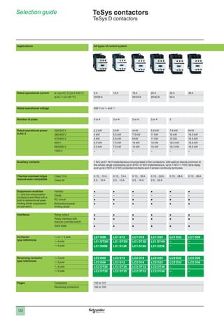
  • 1. 2 1 3 4 5 6 7 8 9 10 2 1 3 4 5 6 7 8 9 10 122 Applications All types of control system Rated operational current le max AC-3 (Ue y 440 V) 9 A 12 A 18 A 25 A 32 A 38 A le AC-1 (q y 60 °C) 20/25 A 25/32 A 25/40 A 50 A Rated operational voltage 690 V on a and c Number of poles 3 or 4 3 or 4 3 or 4 3 or 4 3 Rated operational power in AC-3 220/240 V 2.2 kW 3 kW 4 kW 5.5 kW 7.5 kW 9 kW 380/400 V 4 kW 5.5 kW 7.5 kW 11 kW 15 kW 18.5 kW 415/440 V 4 kW 5.5 kW 9 kW 11 kW 15 kW 18.5 kW 500 V 5.5 kW 7.5 kW 10 kW 15 kW 18.5 kW 18.5 kW 660/690 V 5.5 kW 7.5 kW 10 kW 15 kW 18.5 kW 18.5 kW 1000 V – – – – – – Auxiliary contacts 1 N/C and 1 N/O instantaneous incorporated in the contactors, with add-on blocks common to the whole range comprising up to 4 N/C or N/O instantaneous, up to 1 N/O + 1 N/C time delay and up to 2 N/O or 2 N/C protected contacts and 2 screen continuity terminals. Thermal overload relays manual-auto compatible Class 10 A 0.10…10 A 0.10…13 A 0.10…18 A 0.10…32 A 0.10…38 A 0.10…38 A Class 20 2.5…10 A 2.5…13 A 2.5…18 A 2.5…32 A Suppressor modules (c and low consumption contactors are fitted with a built-in bidirectional peak limiting diode suppressior as standard) Varistor p p p p p p Diode – – – – – – RC circuit p p p p p p Bidirectional peak limiting diode p p p p p p Interfaces Relay output p p p p p p Relay interface with manual override switch p p p p p p Solid state p p p p p p Contactor type references a or c 3 pole LC1 D09 LC1 D12 LC1 D18 LC1 D25 LC1 D32 LC1 D38 a 4 pole LC1 DT20/ LC1 D098 LC1 DT25/ LC1 D128 LC1 DT32/ LC1 D188 LC1 DT40/ LC1 D258 – – c 4 pole – – Reversing contactor type references a 3 pole LC2 D09 LC2 D12 LC2 D18 LC2 D25 LC2 D32 LC2 D38 c 3 pole LC2 D09 LC2 D12 LC2 D18 LC2 D25 LC2 D32 LC2 D38 a 4 pole LC2 DT20 LC2 DT25 LC2 DT32 LC2 DT40 – – c 4 pole LC2 DT20 LC2 DT25 LC2 DT32 LC2 DT40 – – Pages Contactors 152 to 157 Reversing contactors 162 to 165 Selection guide TeSys contactors TeSys D contactors
  • 2. 2 1 3 4 5 6 7 8 9 10 2 1 3 4 5 6 7 8 9 10 123 40 A 50 A 65 A 80 A 95 A 115 A 150 A 60 A 80 A 125 A 200 A 690 V a or c 1000 V on a supply, 690 V on c supply 3 4 3 3 4 3 4 3 3 4 3 11 kW 15 kW 18.5 kW 22 kW 25 kW 30 kW 40 kW 18.5 kW 22 kW 30 kW 37 kW 45 kW 55 kW 75 kW 22 kW 25/30 kW 30 kW 45 kW 45 kW 59 kW 80 kW 22 kW 30 kW 37 kW 55 kW 55 kW 75 kW 90 kW 30 kW 33 kW 37 kW 45 kW 45 kW 80 kW 100 kW – – – 45 kW 45 kW 75 kW 90 kW 1 N/C and 1 N/O instantaneous incorporated in the contactors, with add-on blocks common to the whole range comprising up to 4 N/C or N/O instantaneous, up to 1 N/O + 1 N/C time delay and up to 2 N/O or 2 N/C protected contacts and 2 screen continuity terminals. 13…40 A 13…50 A 13…65 A 17…104 A 17…104 A 60…150 A 60…150 A 13…40 A 13…50 A 13…65 A 17…80 A 60…150 A 60…150 A p p p p p p p p p p – p p p p p p p p – – – p p p p p p p p p p p p p p p p p p p – – – p p p p p p p p p p p p p p p p p p p p p p p p p p p p p p p p – LC1 D40A LC1 D50A LC1 D65A LC1 D80 LC1 D95 LC1 D115 LC1 D150 LC1 DT60A – LC1 DT80A LC1 D80 – LC1 D115 – LC1 DT60A – LC1 DT80A LC1 D80 – LC1 D115 – LC2 D40A LC2 D50A LC2 D65A LC2 D80 LC2 D95 LC2 D115 LC2 D150 LC2 D40A LC2 D50A LC2 D65A – – – – – – – LC2 D80 – LC2 D115 – – – – – – – – 152 to 157 162 to 165
  • 3. 2 1 3 4 5 6 7 8 9 10 2 1 3 4 5 6 7 8 9 10 124 Applications Automation systems Rated operational current le max AC-3 (Ue y 440 V) 9 A 12 A 18 A le AC-1 (q y 60 °C) 20/25 A 20/25 A 25/32 A Rated operational voltage 690 V Number of poles 3 or 4 3 or 4 3 or 4 Rated operational power in AC-3 220/240 V 2.2 kW 3 kW 4 kW 380/400 V 4 kW 5.5 kW 7.5 kW 415/440 V 4 kW 5.5 kW 9 kW 500 V 5.5 kW 7.5 kW 10 kW 660/690 V 5.5 kW 7.5 kW 10 kW Coil consumption 2.4 W (100 mA - 24 V) Operating ranges 0.7…1.25 Uc Operating time at 20 °C and at Uc Closing 70 ms Opening 25 ms Auxiliary contact block modules 1 N/C and 1 N/O instantaneous contacts incorporated in the contactors, with add-on blocks common to the whole range, comprising up to 2 N/C or 2 N/O instantaneous standard contacts Interference suppression Built-in suppression as standard, by bi-directional peak limiting diode Contactor type 3-pole LC1 D09 LC1 D12 LC1 D18 4-pole LC1 DT20/D098 LC1 DT25/D128 LC1 DT32/D188 Reversing contactor type 3-pole LC2 D09 LC2 D12 LC2 D18 4-pole LC2 DT20 LC2 DT25 LC2 DT32 Pages Contactors 152 to 157 Reversing contactors 162 to 165 (1) With low consumption kit LA4 DBL (see page 173). (2) With 2 low consumption kits LA4 DBL (see page 173). Selection guide TeSys contactors TeSys D low consumption contactors
  • 4. 2 1 3 4 5 6 7 8 9 10 2 1 3 4 5 6 7 8 9 10 125 25 A 32 A 38 A 40 A 50 A 65 A 25/40 A 50 A 50 A 60 A – 80 A 690 V 690 V 3 or 4 3 3 3 3 3 5.5 kW 7.5 kW 9 kW 11 kW 15 kW 18.5 kW 11 kW 15 kW 18.5 kW 18.5 kW 22 kW 30 kW 11 kW 15 kW 18.5 kW 22 kW 25/30 kW 30 kW 15 kW 18.5 kW 18.5 kW 22 kW 30 kW 37 kW 15 kW 18.5 kW 18.5 kW 30 kW 33 kW 37 kW 2.4 W (100 mA - 24 V) 0.6 W (25 mA - 24 V) for relay LA4 DFB + the power consumed by the contactor coil 0.7…1.25 Uc – – – 70 ms – – – 25 ms – – – 1 N/C and 1 N/O instantaneous contacts incorporated in the contactors, with add-on blocks common to the whole range, comprising up to 2 N/C or 2 N/O instantaneous standard contacts Built-in suppression as standard, by bi-directional peak limiting diode LC1 D25 LC1 D32 LC1 D38 LC1 D40A (1) LC1 D50A (1) LC1 D65A (1) LC1 DT40/D258 – – LC1 DT80A (1) LC2 D25 LC2 D32 LC2 D38 LC2 D40A (2) LC2 D50A (2) LC2 D65A (2) LC2 DT40 152 to 157 162 to 165
  • 5. 126 Selection� 5 Operational current and power conforming to IEC (q y 60 °C) Contactor size LC1/ LP1 K06 LC1/ LP1 K09 LC1 K12 LC1 K16 LC1 D09 LC1 D12 LC1 D18 LC1 D25 LC1 D32 LC1 D38 LC1 D40A Maximum operational current. in AC-3 y 440 V A 6 9 12 16 9 12 18 25 32 38 40 Rated operational power P . (standard motor power ratings) 220/240 V kW 1.5 2.2 3 3 2.2 3 4 5.5 7.5 9 11 380/400 V kW 2.2 4 5.5 7.5 4 5.5 7.5 11 15 18.5 18.5 415 V kW 2.2 4 5.5 7.5 4 5.5 9 11 15 18.5 22 440 V kW 3 4 5.5 7.5 4 5.5 9 11 15 18.5 22 500 V kW 3 4 4 5.5 5.5 7.5 10 15 18.5 18.5 22 660/690 V kW 3 4 4 4 5.5 7.5 10 15 18.5 18.5 30 1000 V kW – – – – – – – – – – – Maximum operating rate in operating cycles/hour (1) On-load factor Operational power LC1 D09 LC1 D12 LC1 D18 LC1 D25 LC1 D32 LC1 D38 LC1 D40A y 85 % P – – – – 1200 1200 1200 1200 1000 1000 1000 0.5 P – – – – 3000 3000 2500 2500 2500 2500 2500 y 25 % P – – – – 1800 1800 1800 1800 1200 1200 1200 Operational current and power conforming to UL, CSA (q y 60 °C) Contactor size LC1/ LP1 K06 LC1/ LP1 K09 LC1/ LP1 K12 LC1 D09 LC1 D12 LC1 D18 LC1 D25 LC1 D32 LC1 D38 LC1 D40A Maximum operational current. in AC-3 y 440 V A 6 9 12 9 12 18 25 32 – 40 Rated operational power P . (standard motor power ratings . 60 Hz) 200/208 V HP 1.5 2 3 2 3 5 7.5 10 – 10 230/240 V HP 1.5 3 3 2 3 5 7.5 10 – 10 460/480 V HP 3 5 7.5 5 7.5 10 15 20 – 30 575/600 V HP 3 5 10 7.5 10 15 20 25 – 30 (1) Depending on the operational power and the on-load factor (q y 60 °C). Characteristics : pages 140 to 145 References : pages 152 to 157 Dimensions, schemes : pages 182 to 187 Characteristics : pages 140 to 145 References : pages 152 to 157 Dimensions, schemes : pages 182 to 187 Characteristics : pages 140 to 145 References : pages 152 to 157 Dimensions, schemes : pages 182 to 187 Characteristics : pages 140 to 145 References : pages 152 to 157 Dimensions, schemes : pages 182 to 187 TeSys contactors� 5 For utilisation category AC-3 1 2 3 4 5 6 7 8 9 10
  • 6. 127 5 LC1 D50A LC1 D65A LC1 D80 LC1 D95 LC1 D115 LC1 D150 LC1 F185 LC1 F225 LC1 F265 LC1 F330 LC1 F400 LC1 F500 LC1 F630 LC1 F780 LC1 F800 LC1 BL LC1 BM LC1 BP LC1 BR 50 65 80 95 115 150 185 225 265 330 400 500 630 780 800 750 1000 1500 1800 15 18,5 22 25 30 40 55 63 75 100 110 147 200 220 250 220 280 425 500 22 30 37 45 55 75 90 110 132 160 200 250 335 400 450 400 500 750 900 25 30 45 45 59 80 100 110 140 180 220 280 375 425 450 425 530 800 900 30 30 45 45 59 80 100 110 140 200 250 295 400 425 450 450 560 800 900 30 37 55 55 75 90 110 129 160 200 257 355 400 450 450 500 600 750 900 33 37 45 45 80 100 110 129 160 220 280 335 450 475 475 560 670 750 900 . . – – 45 45 65 75 100 100 147 160 185 335 450 450 450 530 530 670 750 LC1 D50A LC1 D65A LC1 D80 LC1 D95 LC1 D115 LC1 D150 LC1 F185 LC1 F225 LC1 F265 LC1 F330 LC1 F400 LC1 F500 LC1 F630 LC1 F780 LC1 F800 LC1 BL LC1 BM LC1 BP LC1 BR 1000 1000 750 750 750 750 750 750 750 750 500 500 500 500 500 120 120 120 120 2500 2500 2000 2000 2000 1200 2000 2000 2000 2000 1200 1200 1200 1200 600 120 120 120 120 . . 1200 1200 1200 1200 1200 1200 1200 1200 1200 1200 1200 1200 1200 600 600 120 120 120 120 LC1 D50A LC1 D65A LC1 D80 LC1 D95 LC1 D115 LC1 D150 LC1 F185 LC1 F225 LC1 F265 LC1 F330 LC1 F400 LC1 F500 LC1 F630 LC1 F780 LC1 F800 50 65 80 95 115 150 185 225 265 330 400 500 630 780 800 15 20 30 30 30 40 50 60 60 75 100 150 250 – 350 15 20 30 30 40 50 60 75 75 100 125 200 300 450 400 40 40 60 60 75 100 125 150 150 200 250 400 600 900 900 . . 40 50 60 60 100 125 150 150 200 250 300 500 800 – 900 5 1 2 3 4 5 6 7 8 9 10
  • 7. 128 Selection (continued)� 5 Selection according to required electrical durability, in category AC-3 (Ue�  y 440 V) Control of 3-phase asynchronous squirrel cage motors with breaking whilst running. The current broken (Ic) in category AC-3 is equal to the rated operational current (Ie) of the motor. Operational power in kW-50 Hz. Example: Asynchronous motor with  P = 5.5 kW - Ue = 400 V - Ie = 11 A - Ic = Ie = 11 A. or asynchronous motor with  P = 5.5 kW - Ue = 415 V - Ie = 11 A - Ic = Ie = 11 A. 3 million operating cycles required. . The above selection curves show the contactor rating needed: LC1 D18. Selection according to required electrical durability, in category AC-3 (Ue = 660/690 V) (1) Control of 3-phase asynchronous squirrel cage motors with breaking whilst running. The current broken (Ic) in category AC-3 is equal to the rated operational current (Ie) of the motor. (1) For Ue = 1000 V, use the 660/690 V curves, but do not exceed the operational current at the operational power indicated for 1000 V. 2 1 3 4 5 6 7 8 9 10 12 16 18 20 30 25 32 40 37 50 65 80 115 95 150 0,5 0,6 0,8 1 1,5 2 4 6 8 10 LC1-D09 LC1, LP1, LP4 K09 LC1, LP1, LP4 K06 LC1 D12 LC1 K16 LC1, LP1, LP4 K12 LC1 D18 LC1 D25 LC1 D32 LC1 D38 LC1 D40A LC1 D50A LC1 D65A LC1 D80 LC1 D95 LC1 D115 LC1 D150 200 0,55 0,75 1,5 2,2 3 4 5,5 7,5 11 15 18,5 22 25 30 230 V 400 V 0,75 1,5 2,2 4 5,5 7,5 11 15 18,5 22 30 37 kW 1,5 2,2 5,5 7,5 11 15 18,5 22 37 45 55 75 30 440 V kW kW 45 55 75 Millions of operating cycles Current broken in A 2 1 3 4 5 6 7 8 9 10 12 16 18 20 30 25 32 40 37 50 65 80 115 95 150 0,5 0,6 0,8 1 1,5 2 4 6 8 10 LC1-D09 LC1, LP1, LP4 K09 LC1, LP1, LP4 K06 LC1 D12 LC1 K16 LC1, LP1, LP4 K12 LC1 D18 LC1 D25 LC1 D32 LC1 D38 LC1 D40A LC1 D50A LC1 D65A LC1 D80 LC1 D95 LC1 D115 LC1 D150 200 0,55 0,75 1,5 2,2 3 4 5,5 7,5 11 15 18,5 22 25 30 230 V 400 V 0,75 1,5 2,2 4 5,5 7,5 11 15 18,5 22 30 37 kW 1,5 2,2 5,5 7,5 11 15 18,5 22 37 45 55 75 30 440 V kW kW 45 55 75 Millions of operating cycles Current broken in A 0,6 0,8 1 1,5 2 3 4 6 8 10 LC1 D09 LC1 D12 LC1 D18 LC1 D25 LC1 D32, LC1 D38 LC1 D40A LC1 D50A LC1 D65A LC1 D80 LC1 D95 LC1 D115 LC1 D150 200 1 2 3 4 5 6 7 8 9 6,6 10 11 15 17 20 22 35 33 40 42 48 50 60 90 80 100 Millions of operating cycles Current broken in A 0,6 0,8 1 1,5 2 3 4 6 8 10 LC1 D09 LC1 D12 LC1 D18 LC1 D25 LC1 D32, LC1 D38 LC1 D40A LC1 D50A LC1 D65A LC1 D80 LC1 D95 LC1 D115 LC1 D150 200 1 2 3 4 5 6 7 8 9 6,6 10 11 15 17 20 22 35 33 40 42 48 50 60 90 80 100 Millions of operating cycles Current broken in A Characteristics : pages 140 to 145 References : pages 152 to 157 Dimensions, schemes : pages 182 to 187 Characteristics : pages 140 to 145 References : pages 152 to 157 Dimensions, schemes : pages 182 to 187 Characteristics : pages 140 to 145 References : pages 152 to 157 Dimensions, schemes : pages 182 to 187 Characteristics : pages 140 to 145 References : pages 152 to 157 Dimensions, schemes : pages 182 to 187 TeSys contactors� 5 For utilisation category AC-3 1 2 3 4 5 6 7 8 9 10
  • 8. 129 Selection (continued)� 5 Selection according to required electrical durability, in category AC-3 (Ue�  y 440 V) Control of 3-phase asynchronous squirrel cage motors with breaking whilst running. The current broken (Ic) in category AC-3 is equal to the rated operational current (Ie) of the motor. Operational power in kW-50 Hz. Example: Asynchronous motor with  P = 132 kW - Ue = 380 V - Ie = 245 A - Ic = Ie = 245 A or asynchronous motor with  P = 132 kW - Ue = 415 V - Ie = 240 A - Ic = Ie = 240 A 1.5 million operating cycles required. The above selection curves show the contactor rating needed: LC1 F330.� (1) The dotted lines are only applicable to LC1 BL contactors. Selection according to required electrical durability, in category AC-3 (Ue = 660/690 V) Control of 3-phase asynchronous squirrel cage motors with breaking whilst running. The current broken (Ic) in category AC-3 is equal to the rated operational current (Ie) of the motor. Example: Asynchronous motor with P = 132 kW - Ue = 660 V - Ie = 140 A - Ic = Ie = 140 A 1.5 million operating cycles required. The above selection curves show the contactor rating needed: LC1 F330. (1) The dotted lines are only applicable to LC1 BL contactors. 20 30 40 50 60 80 90 100 400 800 1000 2000 (1) 600 0,4 0,8 1 1,5 2 4 6 8 10 5,5 7,5 11 15 18,5 22 25 30 40 55 110 11 15 18,5 22 30 37 45 55 75 90 110 132 160 200 250 335 400 500 750 900 11 15 18,5 22 30 37 45 55 75 90 132 200 285 45 75 200 220 147 220 V 230 V kW kW kW 380 V 400 V 440 V LC1 F185 LC1 F225 LC1 F265 LC1 F330 LC1 F400 LC1 F500 LC1 F780 LC1 F630 LC1 F800 LC1 BP LC1 BR LC1 BL, BM 0,6 200 Millions of operating cycles Current broken in A 20 30 40 50 60 80 90 100 400 800 1000 2000 (1) 600 0,4 0,8 1 1,5 2 4 6 8 10 5,5 7,5 11 15 18,5 22 25 30 40 55 110 11 15 18,5 22 30 37 45 55 75 90 110 132 160 200 250 335 400 500 750 900 11 15 18,5 22 30 37 45 55 75 90 132 200 285 45 75 200 220 147 220 V 230 V kW kW kW 380 V 400 V 440 V LC1 F185 LC1 F225 LC1 F265 LC1 F330 LC1 F400 LC1 F500 LC1 F780 LC1 F630 LC1 F800 LC1 BP LC1 BR LC1 BL, BM 0,6 200 Millions of operating cycles Current broken in A 0,6 0,8 1 1,5 2 4 6 8 10 20 30 40 50 60 80 90 100 400 800 1000 2000 200 600 118 129 170 220 305 355 485 LC1 F185 LC1 F225 LC1 F265 LC1 F330 LC1 F400 LC1 F500 LC1 F780 LC1 F800 LC1 F630 LC1 BP LC1 BR LC1 BL, BM 0,4 kW 110 160 355 335 129 220 670 750 900 475 560 660 V 690 V (1) Millions of operating cycles Current broken in A 0,6 0,8 1 1,5 2 4 6 8 10 20 30 40 50 60 80 90 100 400 800 1000 2000 200 600 118 129 170 220 305 355 485 LC1 F185 LC1 F225 LC1 F265 LC1 F330 LC1 F400 LC1 F500 LC1 F780 LC1 F800 LC1 F630 LC1 BP LC1 BR LC1 BL, BM 0,4 kW 110 160 355 335 129 220 670 750 900 475 560 660 V 690 V (1) Millions of operating cycles Current broken in A Characteristics : pages 140 to 145 References : pages 152 to 157 Dimensions, schemes : pages 182 to 187 Characteristics : pages 140 to 145 References : pages 152 to 157 Dimensions, schemes : pages 182 to 187 Characteristics : pages 140 to 145 References : pages 152 to 157 Dimensions, schemes : pages 182 to 187 Characteristics : pages 140 to 145 References : pages 152 to 157 Dimensions, schemes : pages 182 to 187 TeSys contactors� 5 For utilisation category AC-3 1 2 3 4 5 6 7 8 9 10
  • 9. 130 Selection� 5 Maximum operational current (open-mounted device) Contactor size LC1/ LP1 K09 LC1/ LP1 K12 LC1 D09 LC1 DT20 LC1 D12 DT25 LC1 D18 DT32 LC1 D25 DT40 LC1 D32 LC1 D38 LC1 D40A DT60A Maximum operating rate . in operating cycles/hour 600 600 600 600 600 600 600 600 600 600 Connection conforming to IEC 60947-1 Cable c.s.a. mm2 4 4 4 4 4 6 6 10 10 35 Bar c.s.a. mm – – – – – – – – – – Operational current in AC-1 in A, according to the . ambient temperature,. conforming to IEC 60947-1 y 40 °C A 20 20 25 20 25 32 40 50 50 60 y 60 °C A 20 20 25 20 25 32 40 50 50 60 y 70 °C A (at UC) (1) (1) 17 (1) 17 22 28 35 35 42 Maximum operational. power y 60 °C 220/230 V kW 8 8 9 8 9 11 14 18 18 21 240 V kW 8 8 9 8 9 12 15 19 19 23 380/400 V kW 14 14 15 14 15 20 25 31 31 37 415 V kW 14 14 17 14 17 21 27 34 34 41 440 V kW 15 15 18 15 18 23 29 36 36 43 500 V kW 17 17 20 17 20 23 33 41 41 49 660/690 V kW 22 22 27 22 27 34 43 54 54 65 1000 V kW – – – – – – – – – – (1) Please consult your Regional Sales Office. Increase in operational current by parallel connection of poles Apply the following coefficients to the currents or power values given above; these coefficients take into account an often unbalanced current distribution between the poles: 2 poles in parallel: K = 1.6 3 poles in parallel: K = 2.25 4 poles in parallel: K = 2.8 b b b Selection according to required electrical durability, in category AC-1 (Ue�  y 440 V) Control of resistive circuits (cos φ u 0.95). The current broken (Ic) in category AC-1 is equal to the current (Ie) normally drawn by the load. Example: Ue = 220 V - Ie = 50 A q y 40 °C - Ic�������������  ������������ =�����������  ���������� Ie��������  ������� =������  ����� 50 A. 2 million operating cycles required. The above selection curves show the contactor rating needed: either LC1 or LP1 D50. b b b 20 25 32 10 2 4 3 6 8 1 40 50 60 80 100 125 200 400 0,1 0,2 0,4 0,6 0,8 1 1,5 2 4 6 8 10 LC1, LP1, LP4 K09 LC1, LP1, LP4 K12 LC1 D09 LC1 D12 LC1 D18 LC1 D25 LC1 D32, LC1 D38 LC1 D40A LC1 D50A LC1 D65A LC1, LP1 D80 LC1 D95 LC1 D115 LC1 D150 250 Millions of operating cycles Current broken in A 20 25 32 10 2 4 3 6 8 1 40 50 60 80 100 125 200 400 0,1 0,2 0,4 0,6 0,8 1 1,5 2 4 6 8 10 LC1, LP1, LP4 K09 LC1, LP1, LP4 K12 LC1 D09 LC1 D12 LC1 D18 LC1 D25 LC1 D32, LC1 D38 LC1 D40A LC1 D50A LC1 D65A LC1, LP1 D80 LC1 D95 LC1 D115 LC1 D150 250 Millions of operating cycles Current broken in A Characteristics : pages 140 to 145 Réferences : pages 152 to 157 Dimensions, schemes : pages 182 to 187 Characteristics : pages 140 to 145 Réferences : pages 152 to 157 Dimensions, schemes : pages 182 to 187 Characteristics : pages 140 to 145 Réferences : pages 152 to 157 Dimensions, schemes : pages 182 to 187 Characteristics : pages 140 to 145 Réferences : pages 152 to 157 Dimensions, schemes : pages 182 to 187 TeSys contactors� 5 For utilisation category AC-1 1 2 3 4 5 6 7 8 9 10
  • 10. 131 5 LC1 D50A LC1 D65A DT80A LC1/ LP1 D80 LC1 D95 LC1 D115 LC1 D150 LC1 F185 LC1 F225 LC1 F265 LC1 F330 LC1 F400 LC1 F500 LC1 F630 LC1 F780 LC1 F800 LC1 BL LC1 BM LC1 BP LC1 BR 600 600 600 600 600 600 600 600 600 600 600 600 600 600 600 120 120 120 120 35 35 50 50 120 120 150 185 185 240 – – – – – – – – – – – – – – – – – – – 2 30 x 5 2 40 x 5 2 60 x 5 2 100 x 5 2 60 x 5 2 50 x 5 2 80 x 5 2 100 x 5 2 100 x 10 80 80 125 125 250 250 275 315 350 400 500 700 1000 1600 1000 800 1250 2000 2750 80 80 125 125 200 200 275 280 300 360 430 580 850 1350 850 700 1100 1750 2400 56 56 80 80 160 160 180 200 250 290 340 500 700 1100 700 600 900 1500 2000 29 29 45 45 80 80 90 100 120 145 170 240 350 550 350 300 425 700 1000 31 31 49 49 83 83 100 110 125 160 180 255 370 570 370 330 450 800 1100 50 50 78 78 135 135 165 175 210 250 300 430 600 950 600 500 800 1200 1600 54 54 85 85 140 140 170 185 220 260 310 445 630 1000 630 525 825 1250 1700 58 58 90 90 150 150 180 200 230 290 330 470 670 1050 670 550 850 1400 2000 65 65 102 102 170 170 200 220 270 320 380 660 750 1200 750 600 900 1500 2100 80 80 135 135 235 235 280 300 370 400 530 740 1000 1650 1000 800 1100 1900 2700 – – 120 120 345 345 410 450 540 640 760 950 1500 2400 1500 1100 1700 3000 4200 . . . . . Example: Ue = 220 V - Ie = 500 A - q y 40 °C - Ic = Ie = 500 A. 2 million operating cycles required. The above selection curves show the contactor rating needed: LC1 F780. (1) The dotted lines are only applicable to LC1 F225 contactors. b b b 20 40 50 60 80 100 200 300 400 600 800 1000 2000 4000 0,1 0,2 0,4 0,6 0,8 1 2 4 6 8 10 LC1 F185 LC1 F265 LC1 F225 LC1 F330 275 315 350 500 700 1600 LC1 F400 LC1 F500 LC1 F630 LC1 F800 LC1 F780 LC1 BL, BM LC1 BP LC1 BR (1) Millions of operating cycles Current broken in A 20 40 50 60 80 100 200 300 400 600 800 1000 2000 4000 0,1 0,2 0,4 0,6 0,8 1 2 4 6 8 10 LC1 F185 LC1 F265 LC1 F225 LC1 F330 275 315 350 500 700 1600 LC1 F400 LC1 F500 LC1 F630 LC1 F800 LC1 F780 LC1 BL, BM LC1 BP LC1 BR (1) Millions of operating cycles Current broken in A 5 1 2 3 4 5 6 7 8 9 10
  • 11. 132 Selection� 5 Maximum breaking current Category AC-2: slip ring motors - breaking the starting current. Category AC-4: squirrel cage motors - breaking the starting current. Contactor size LC1/ LP1 K06 LC1/ LP1 K09 LC1/ LP1 K12 LC1 D09 LC1 D12 LC1 D18 LC1 D25 LC1 D32 LC1 D38 LC1 D40A In category AC-4 (le max) Ue y 440 V le max broken = . 6 x l motor A 36 54 54 54 72 108 150 192 192 240 440 V Ue y 690 V le max broken = . 6 x l motor A 26 40 40 40 50 70 90 105 105 150 Depending on the maximum operating rate (1) and the on-load factor, q y 60 °C (2) From 150 and 15 % to 300 and 10 % A 20 30 30 30 40 45 75 80 80 110 From 150 and 20 % to 600 and 10 % A 18 27 27 27 36 40 67 70 70 96 From 150 and 30 % to 1200 and 10 % A 16 24 24 24 30 35 56 60 60 80 From 150 and 55 % to 2400 and 10 % A 13 19 19 19 24 30 45 50 50 62 From 150 and 85 % to 3600 and 10 % A 10 16 16 16 21 25 40 45 45 53 (1) Do not exceed the maximum number of operating cycles.. (2) For temperatures higher than 60 °C, use a maximum operating rate value equal to 80% of the actual value when selecting from the tables. Counter current braking (plugging) The current varies from the maximum plug-braking current to the rated motor current. The making current must be compatible with the rated making and breaking capacities of the contactor. As breaking normally takes place at a current value at or near the locked rotor current, the contactor can be selected using the criteria for categories AC-2 and AC-4. Permissible AC-4 power rating for 200 000 operating cycles Operational voltage LCp/ LPp K06 LCp/ LPp K09 LCp LPp K12 LCp D09 LCp D12 LCp D18 LCp D25 LCp D32 LCp D38 LCp D40A 220/230 V kW 0.75 1.1 1.1 1.5 1.5 2.2 3 4 4 4 380/400 V kW 1.5 2.2 2.2 2.2 3.7 4 5.5 7.5 7.5 9 415 V kW 1.5 2.2 2.2 2.2 3 3.7 5.5 7.5 7.5 9 440 V kW 1.5 2.2 2.2 2.2 3 3.7 5.5 7.5 7.5 11 500 V kW 2.2 3 3 3 4 5.5 7.5 9 9 11 660/690 V kW 3 4 4 4 5.5 7.5 10 11 11 15 TeSys contactors� 5 For utilisation categories AC-2 or AC-4 Characteristics : pages 140 to 145 References : pages 152 to 157 Dimensions, schemes : pages 182 to 187 Characteristics : pages 140 to 145 References : pages 152 to 157 Dimensions, schemes : pages 182 to 187 1 2 3 4 5 6 7 8 9 10
  • 12. 133 5 . . LC1 D50A LC1 D65A LC1 D80 LC1 D95 LC1 D115 LC1 D150 LC1 F185 LC1 F225 LC1 F26 LC1 F330 LC1 F40 LC1 F500 LC1 F630 LC1 F780 LC1 F800 LC1 BL LC1 BM LC1 BP LC1 BR . . 300 390 480 570 630 830 1020 1230 1470 1800 2220 2760 3360 4260 3690 4320 5000 7500 9000 . . 170 210 250 250 540 640 708 810 1020 1410 1830 2130 2760 2910 2910 4000 4800 5400 6600 140 160 200 200 280 310 380 420 560 670 780 1100 1400 1600 1600 2250 3000 4500 5400 120 148 170 170 250 280 350 400 500 600 700 950 1250 1400 1400 2000 2400 3750 5000 100 132 145 145 215 240 300 330 400 500 600 750 950 1100 1100 1500 2000 3000 3600 80 110 120 120 150 170 240 270 320 390 450 600 720 820 820 1000 1500 2000 2500 70 90 100 100 125 145 170 190 230 290 350 500 660 710 710 750 1000 1500 1800 . . . . . . . . LCp D50A LCp D65A LCp D80 LCp D95 LC1 D115 LC1 D150 LC1 F185 LC1 F225 LC1 F265 LC1 F330 LC1 F400 LC1 F500 LC1 F630 LC1 F780 LC1 F800 LC1 BL LC1 BM LC1 BP LC1 BR 5.5 7.5 7.5 9 9 11 18.5 22 28 33 40 45 55 63 63 90 110 150 200 11 11 15 15 18.5 22 33 40 51 59 75 80 100 110 110 160 160 220 250 11 11 15 15 18.5 22 37 45 55 63 80 90 100 110 110 160 160 250 280 11 15 15 15 18.5 22 37 45 59 63 80 100 110 132 132 160 200 250 315 15 15 22 22 30 37 45 55 63 75 90 110 132 150 150 180 200 250 355 15 18.5 25 25 30 45 63 75 90 110 129 140 160 185 185 200 250 315 450 5 1 2 3 4 5 6 7 8 9 10
  • 13. 134 TeSys contactors� 5 For utilisation categories AC-2 or AC-4 Selection (continued)� 5 Selection according to required electrical durability, in categories AC-2 or AC-4 (Ue�  y 440 V) Control of 3-phase asynchronous squirrel cage motors (AC-4) or slip ring motors (AC-2) with breaking whilst motor stalled. The current broken (Ic) in AC-2 is equal to 2.5 x Ie. The current broken (Ic) in AC-4 is equal to 6 x Ie. (Ie = rated operational current of the motor). Example: Asynchronous motor with P = 5.5 kW - Ue  = 400 V - Ie  = 11 A. Ic = 6 x Ie = 66 A or asynchronous motor with P = 5.5 kW - Ue = 415 V - Ie = 11 A. Ic = 6 x Ie = 66 A. 200 000 operating cycles required. The above selection curves show the contactor rating needed: LC1 D25. (1) The dotted lines are only applicable to LC1, LP1 K12 contactors. b b b b Selection according to required electrical durability, use in category AC-4 (440 V Ue y 690 V) Control of 3-phase asynchronous squirrel cage motors with breaking whilst motor stalled The current broken (Ic) in AC-2 is equal to 2.5 x Ie. The current broken (Ic) in AC-4 is equal to 6 x Ie. (Ie = rated operational current of the motor). 5 6 7 8 9 10 20 30 36 40 50 54 80 72 108 150 192 240 300 390 480 630 828 1000 570 0,01 0,02 0,03 0,04 0,06 0,05 0,08 0,1 0,2 0,4 0,6 0,8 1 LC1 D09 LC1 D12 LC1 D18 LC1 D25 LC1 D32 et D38 LC1 D40A LC1 D50A LC1 D65A LC1 D80 LC1 D95 LC1 D115 LC1 D150 LC1, LP1, LP4 K09,K12 LC1, LP1, LP4 K06 (1) Millions of operating cycles Current broken in A 5 6 7 8 9 10 20 30 36 40 50 54 80 72 108 150 192 240 300 390 480 630 828 1000 570 0,01 0,02 0,03 0,04 0,06 0,05 0,08 0,1 0,2 0,4 0,6 0,8 1 LC1 D09 LC1 D12 LC1 D18 LC1 D25 LC1 D32 et D38 LC1 D40A LC1 D50A LC1 D65A LC1 D80 LC1 D95 LC1 D115 LC1 D150 LC1, LP1, LP4 K09,K12 LC1, LP1, LP4 K06 (1) Millions of operating cycles Current broken in A 5 6 7 8 9 10 20 30 40 50 90 70 105 121 210 250 300 400 500 640 800 1000 540 0,01 0,02 0,03 0,04 0,06 0,05 0,08 0,07 0,1 0,2 0,4 0,6 0,8 1 LC1 D09 LC1 D12 LC1 D18 LC1 D25 LC1 D40A LC1 D50A LC1 D65A LC1 D80 LC1 D95 LC1 D115 LC1 D150 150 LC1 D32, D38 Millions of operating cycles Current broken in A 5 6 7 8 9 10 20 30 40 50 90 70 105 121 210 250 300 400 500 640 800 1000 540 0,01 0,02 0,03 0,04 0,06 0,05 0,08 0,07 0,1 0,2 0,4 0,6 0,8 1 LC1 D09 LC1 D12 LC1 D18 LC1 D25 LC1 D40A LC1 D50A LC1 D65A LC1 D80 LC1 D95 LC1 D115 LC1 D150 150 LC1 D32, D38 Millions of operating cycles Current broken in A Characteristics : pages 140 to 145 References : pages 152 to 157 Dimensions, schemes : pages 182 to 187 Characteristics : pages 140 to 145 References : pages 152 to 157 Dimensions, schemes : pages 182 to 187 1 2 3 4 5 6 7 8 9 10
  • 14. 135 Selection (continued)� 5 Selection according to required electrical durability, in categories AC-2 or AC-4 (Ue�  y 440 V) Control of 3-phase asynchronous squirrel cage motors (AC-4) or slip ring motors (AC-2) with breaking whilst motor stalled. The current broken (Ic) in AC-4 is equal to 6 x Ie. (Ie = rated operational current of the motor). Example: Asynchronous motor with P = 90 kW - Ue��������������������������������������������  ������������������������������������������� = 380 V - Ie�������������������������������  ������������������������������ = 170�������������������������  ������������������������ A. Ic = 6 x Ie = 1020���  �� A . or asynchronous motor with P = 90 kW - Ue = 415 V - Ie = 165 A. Ic = 6 x Ie = 990 A. 60 000 operating cycles required. The above selection curves show the contactor rating needed: LC1 F265. b b b Selection according to required electrical durability, use in category AC-4 (440 V Ue y 690 V) Control of 3-phase asynchronous squirrel cage motors with breaking whilst motor stalled. The current broken (Ic) in AC-4 is equal to 6 x Ie. (Ie = rated operational current of the motor). 6000 10 000 100 200 400 600 800 1020 1470 2220 3360 4260 3690 2760 1230 1800 5000 8000 20 000 1 0,8 0,6 0,4 0,2 0,1 0,08 0,06 0,04 0,02 0,01 LC1 F185 LC1 F225 LC1 F265 LC1 F330 LC1 F400 LC1 F500 LC1 F630 LC1 F800 LC1 F780 LC1 BL, BM LC1 BP LC1 BR Millions of operating cycles Current broken in A 6000 10 000 100 200 400 600 800 1020 1470 2220 3360 4260 3690 2760 1230 1800 5000 8000 20 000 1 0,8 0,6 0,4 0,2 0,1 0,08 0,06 0,04 0,02 0,01 LC1 F185 LC1 F225 LC1 F265 LC1 F330 LC1 F400 LC1 F500 LC1 F630 LC1 F800 LC1 F780 LC1 BL, BM LC1 BP LC1 BR Millions of operating cycles Current broken in A 10 000 100 200 400 600 800 1000 2000 4000 8000 20 000 1 0,8 0,6 0,4 0,2 0,1 0,08 0,06 0,04 0,02 0,01 LC1 F185 LC1 F225 LC1 F265 LC1 F330 LC1 F400 LC1 F500 LC1 F630 LC1 F780, F800 LC1 BL, BM LC1 BP LC1 BR Millions of operating cycles Current broken in A 10 000 100 200 400 600 800 1000 2000 4000 8000 20 000 1 0,8 0,6 0,4 0,2 0,1 0,08 0,06 0,04 0,02 0,01 LC1 F185 LC1 F225 LC1 F265 LC1 F330 LC1 F400 LC1 F500 LC1 F630 LC1 F780, F800 LC1 BL, BM LC1 BP LC1 BR Millions of operating cycles Current broken in A TeSys contactors� 5 For utilisation categories AC-2 or AC-4 Characteristics : pages 140 to 145 References : pages 152 to 157 Dimensions, schemes : pages 182 to 187 Characteristics : pages 140 to 145 References : pages 152 to 157 Dimensions, schemes : pages 182 to 187 1 2 3 4 5 6 7 8 9 10
  • 15. 136 Selection 5 + – 2 poles + – 3 poles + – 4 poles 1 pole + – Rated operational current (Ie) in Amperes, in utilisation category DC-1, resistive loads: time constant L __ R y 1 ms, ambient temperature y 60 °C Rated opera- tional voltage Ue No. of poles connec- ted in series Contactor rating (1) LC1 D09 LC1 DT20 LC1 D12 DT25 LC1 D18 DT32 LC1 D25 DT40 LC1 D32 LC1 D38 LC1 D40A LC1 DT60A V 24 1 20 20 20 25 32 40 40 50 50 2 20 20 20 25 32 40 40 50 50 3 20 20 20 25 32 40 40 50 50 4 – 20 20 25 32 – – – 50 48/75 1 20 20 20 25 32 40 40 50 50 2 20 20 20 25 32 40 40 50 50 3 20 20 20 25 32 40 40 50 50 4 – 20 20 25 32 – – – 50 125 1 4 4 4 4 7 7 7 7 7 2 20 20 20 25 32 40 40 50 50 3 20 20 20 25 32 40 40 50 50 4 – 20 20 25 32 – – – 50 250 1 1 1 1 1 1 1 1 1 1 2 4 4 4 4 7 7 7 7 7 3 20 20 20 25 32 40 40 50 50 4 – 20 20 25 32 – – – 50 300 3 4 4 4 4 7 7 7 7 – 4 – 20 20 25 32 – – – 50 460 1 – – – – – – – – – 4 – – – – – – – – – 900 2 – – – – – – – – – 1200 3 – – – – – – – – – 1500 4 – – – – – – – – – Rated operational current (Ie) in Amperes, in utilisation category DC-2 to DC-5, inductive loads: time constant L __ R y 15 ms, ambient temperature y 60 °C Rated oper- ational voltage Ue No. of poles connec- ted in series C���������������� ontactor rating� (1) LC1 D09 LC1 DT20 LC1 D12 DT25 LC1 D18 DT32 LC1 D25 DT40 LC1 D32 LC1 D38 LC1 D40A LC1 DT60A V 24 1 20 20 20 25 32 40 40 50 50 2 20 20 20 25 32 40 40 50 50 3 20 20 20 25 32 40 40 50 50 4 – 20 20 25 32 – – – 50 48/75 1 20 20 20 25 32 40 40 50 50 2 20 20 20 25 32 40 40 50 50 3 20 20 20 25 32 40 40 50 50 4 – 20 20 25 32 – – – 50 125 1 2 2 2 2 3 3 3 4 4 2 20 20 20 25 32 40 40 50 50 3 20 20 20 25 32 40 40 50 50 4 – 20 20 25 32 – – – 50 250 1 0,5 0,5 0,5 0,5 0,5 0,5 0,5 1 1 2 2 2 2 2 3 3 3 4 4 3 8 8 8 8 32 40 40 50 50 4 – 20 20 25 32 – – – 50 300 3 2 2 2 2 3 3 3 3 3 4 – 8 8 8 32 – – – 50 460 1 – – – – – – – – – 4 – – – – – – – – – 900 2 – – – – – – – – – 1200 3 – – – – – – – – – 1500 4 – – – – – – – – – (1) For rated operational currents of contactors LC1 and LP1 K: please consult your Regional Sales Office. TeSys contactors 5 For utilisation categories DC-1 to DC-5 Characteristics: pages 140 to 145 References: pages 152 to 157 Dimensions, schemes: pages 182 to 187 Characteristics: pages 140 to 145 References: pages 152 to 157 Dimensions, schemes: pages 182 to 187
  • 16. 137 5 5 LC1 D50A LC1 D65A LC1 DT80A LC1 D80 LC1 D95 LC1 D115 LC1 D150 LC1 F185 LC1 F225 LC1 F265 LC1 F330 LC1 F400 LC1 F500 LC1 F630 LC1 F780 LC1 F800 LC1 BL LC1 BM LC1 BP LC1 BR 65 65 65 100 100 200 200 240 260 300 360 430 580 850 1300 850 700 1100 1750 2400 65 65 65 100 100 200 200 240 260 300 360 430 580 850 1300 850 700 1100 1750 2400 65 65 65 100 100 200 200 240 260 300 360 430 580 850 1300 850 700 1100 1750 2400 – – 65 100 – 200 – 240 260 300 360 430 580 850 1300 850 700 1100 1750 2400 65 65 65 100 100 200 200 240 260 300 360 430 580 850 1300 850 700 1100 1750 2400 65 65 65 100 100 200 200 240 260 300 360 430 580 850 1300 850 700 1100 1750 2400 65 65 65 100 100 200 200 240 260 300 360 430 580 850 1300 850 700 1100 1750 2400 – – 65 100 – 200 – 240 260 300 360 430 580 850 1300 850 700 1100 1750 2400 7 7 7 12 12 12 12 210 230 270 320 380 520 760 1180 760 700 1100 1750 2400 65 65 65 100 100 200 200 210 230 270 320 380 520 760 1180 760 700 1100 1750 2400 65 65 65 100 100 200 200 240 260 300 360 430 580 850 1300 850 700 1100 1750 2400 – – 65 100 – 200 – 240 260 300 360 430 580 850 1300 850 700 1100 1750 2400 1 1,5 1,5 2 2 10 10 – – – – – – – – – 700 1100 1750 2400 7 7 7 12 12 200 200 190 200 250 280 350 450 700 1000 700 700 1100 1750 2400 65 65 65 100 100 200 200 240 260 300 360 430 580 850 1300 850 700 1100 1750 2400 – – 65 100 – 200 – 240 260 300 360 430 580 850 1300 850 700 1100 1750 2400 7 7 7 12 12 200 200 190 200 250 280 350 450 700 1000 700 700 1100 1750 2400 – – 65 100 – 200 – 240 260 300 360 430 580 850 1000 850 700 1100 1750 2400 – – – – – – – – – – – – – – – – 700 1100 1750 2400 – – – – – 200 – 190 200 250 280 350 450 700 1000 700 700 1100 1750 2400 – – – – – – – – – – – – – – – – 700 1100 1750 2400 – – – – – – – – – – – – – – – – 700 1100 1750 2400 – – – – – – – – – – – – – – – – 700 1100 1750 2400 LC1 D50A LC1 D65A LC1 DT80A LC1 D80 LC1 D95 LC1 D115 LC1 D150 LC1 F185 LC1 F225 LC1 F265 LC1 F330 LC1 F400 LC1 F500 LC1 F630 LC1 F780 LC1 F800 LC1 BL LC1 BM LC1 BP LC1 BR 65 65 65 100 100 200 200 240 260 300 360 430 580 850 1300 850 700 1100 1750 2400 65 65 65 100 100 200 200 240 260 300 360 430 580 850 1300 850 700 1100 1750 2400 65 65 65 100 100 200 200 240 260 300 360 430 580 850 1300 850 700 1100 1750 2400 – – 65 100 – 200 – 240 260 300 360 430 580 850 1300 850 700 1100 1750 2400 65 65 65 100 100 200 200 240 260 300 360 430 580 850 1300 850 700 1100 1750 2400 65 65 65 100 100 200 200 240 260 300 360 430 580 850 1300 850 – – – – 65 65 65 100 100 200 200 240 260 300 360 430 580 850 1300 850 700 1100 1750 2400 – – 65 100 – 200 – 240 260 300 360 430 580 850 1300 850 700 1100 1750 2400 4 4 4 5 5 10 10 – – – – – – – – – 700 1100 1750 2400 65 65 65 100 100 200 200 160 180 250 300 350 500 700 1000 700 700 1100 1750 2400 65 65 65 100 100 200 200 240 240 280 310 350 550 850 1000 850 700 1100 1750 2400 – – 65 100 – 200 – 240 240 280 310 350 550 850 1000 850 700 1100 1750 2400 1 1.5 1.5 1 1 3 3 – – – – – – – – – 700 1100 1750 2400 4 4 4 5 5 200 200 140 160 220 280 310 480 680 900 680 700 1100 1750 2400 65 65 65 100 100 200 200 160 180 250 300 350 500 700 1000 700 700 1100 1750 2400 – – 65 100 – 200 – 240 260 300 360 430 580 850 1300 850 700 1100 1750 2400 3 3 3 5 5 200 200 140 160 220 280 310 480 680 900 680 700 1100 1750 2400 – – 65 100 – 200 – 240 260 300 360 430 580 850 1300 850 700 1100 1750 2400 – – – – – – – – – – – – – – – – 700 1100 1750 2400 – – – – – 200 – 140 160 220 280 310 480 680 800 680 700 1100 1750 2400 – – – – – – – – – – – – – – – – 700 1100 1750 2400 – – – – – – – – – – – – – – – – 700 1100 1750 2400 – – – – – – – – – – – – – – – – 700 1100 1750 2400 Characteristics: pages 140 to 145 References: pages 152 to 157 Dimensions, schemes: pages 182 to 187 Characteristics: pages 140 to 145 References: pages 152 to 157 Dimensions, schemes: pages 182 to 187
  • 17. 138 Selection� 5 Selection according to required electrical durability, use in categories DC-1 to DC-5 The criteria for contactor selection are: the rated operational current Ie, the rated operational voltage Ue, the utilisation category and the time constant L/R, the required electrical durability. b b b b Maximum operating rate (operating cycles) The following limits must not be exceeded: 120 operating cycles/hour at rated operational current Ie. Electrical durability Example Series wound motor - P = 1.5 kW - Ue = 200 V - Ie = 7.5 A. Utilisation: reversing, inching. Utilisation category = DC-5. Select contactor LC1 D09 with 3 poles in series. The power broken is: Pc total = 2.5 x 200 x 7.5 = 3.75 kW. The power broken per pole is: 1.25 kW. The electrical durability read from the curve is u 3 millions of operating cycles. b b b b b Use of poles in parallel Electrical durability can be increased by using poles connected in parallel. With N poles connected in parallel, the electrical durability becomes: electrical durability read from the curves x N x 0.7. Note: 1 When the poles are connected in parallel, the maximum operational currents indicated on pages 136 et 137 must not be exceeded. Note: 2 Ensure that the connections are made in such a way as to equalise the currents in each pole. 0,01 0,02 0,04 0,06 0,08 1 2 4 6 8 10 0,1 0,2 0,4 0,6 0,8 0,2 0,3 0,4 0,5 0,6 0,7 1 0,8 0,9 2 3 4 5 6 7 9 8 10 16 14 20 30 24 32 36 40 50 60 70 90 80 100 LC1 D09 LC1 D12 LC1 D18 LC1 D25 LC1 D32, LC1 D38 LC1 D40A, DT60A LC1 D50A LC1 D65A, DT80A LC1, LP1 D80 LC1 D95 LC1 D115, D150 Millions of operating cycles Power broken per pole in kW 0,01 0,02 0,04 0,06 0,08 1 2 4 6 8 10 0,1 0,2 0,4 0,6 0,8 0,2 0,3 0,4 0,5 0,6 0,7 1 0,8 0,9 2 3 4 5 6 7 9 8 10 16 14 20 30 24 32 36 40 50 60 70 90 80 100 LC1 D09 LC1 D12 LC1 D18 LC1 D25 LC1 D32, LC1 D38 LC1 D40A, DT60A LC1 D50A LC1 D65A, DT80A LC1, LP1 D80 LC1 D95 LC1 D115, D150 Millions of operating cycles Power broken per pole in kW Characteristics: pages 140 to 145 References: pages 152 to 157 Dimensions, schemes: pages 182 to 187 Characteristics: pages 140 to 145 References: pages 152 to 157 Dimensions, schemes: pages 182 to 187 Characteristics: pages 140 to 145 References: pages 152 to 157 Dimensions, schemes: pages 182 to 187 Characteristics: pages 140 to 145 References: pages 152 to 157 Dimensions, schemes: pages 182 to 187 TeSys contactors� 5 For utilisation categories DC-1 to DC-5
  • 18. 139 Selection (continued)� 5 Selection according to required electrical durability, use in categories DC-1 to DC-5 Determining the electrical durability The electrical durability can be read directly from the curves below, having previously calculated the power broken as follows: . P broken = U broken x l broken.. The tables below give the values of Uc and Ic for the various utilisation categories. Power broken Utilisation categories U broken I broken P broken DC-1 Non inductive or slightly inductive loads Ue Ie Ue x Ie DC-2 Shunt wound motors, breaking whilst motor running 0.1 Ue Ie 0.1 Ue x Ie DC-3 Shunt wound motors, reversing, inching Ue 2.5 Ie Ue x 2.5 Ie DC-4 Series wound motors, breaking whilst motor running 0.3 Ue Ie 0.3 Ue x Ie DC-5 Series wound motors, reversing, inching Ue 2.5 Ie Ue x 2.5 Ie Example Series wound motor: P = 40 kW - Ue = 200 V - Ie = 200 A. Utilisation: reversing, inching. Utilisation category = DC-5. Select contactor LC1 F265 with 2 poles in series. The power broken is: Pc total = 2.5 x 200 x 200 = 100 kW. The power broken per pole is 50 kW. The electrical durability read from the curve is 500 000 operating cycles. b b b b 2 3 4 5 6 7 9 10 20 30 40 50 60 70 100 90 200 300 400 500 600 700 1000 800 900 2000 4000 3000 5000 LC1 F185, F225 LC1 F265 LC1 F330 LC1 F400 LC1 F500 LC1 F630, F800 LC1 F780 LC1 BL, BM LC1 BP LC1 BR 0,01 0,02 0,04 0,06 0,08 1 2 4 6 8 10 0,1 0,2 0,4 0,6 0,8 Millions of operating cycles Power broken per pole in kW 2 3 4 5 6 7 9 10 20 30 40 50 60 70 100 90 200 300 400 500 600 700 1000 800 900 2000 4000 3000 5000 LC1 F185, F225 LC1 F265 LC1 F330 LC1 F400 LC1 F500 LC1 F630, F800 LC1 F780 LC1 BL, BM LC1 BP LC1 BR 0,01 0,02 0,04 0,06 0,08 1 2 4 6 8 10 0,1 0,2 0,4 0,6 0,8 Millions of operating cycles Power broken per pole in kW Characteristics: pages 140 to 145 References: pages 152 to 157 Dimensions, schemes: pages 182 to 187 Characteristics: pages 140 to 145 References: pages 152 to 157 Dimensions, schemes: pages 182 to 187 Characteristics: pages 140 to 145 References: pages 152 to 157 Dimensions, schemes: pages 182 to 187 Characteristics: pages 140 to 145 References: pages 152 to 157 Dimensions, schemes: pages 182 to 187 TeSys contactors� 5 For utilisation categories DC-1 to DC-5
  • 19. 140 Contactor type LC1 D09…D18 DT20 and DT25 D25…D38 DT32 and DT40 D40A…D65A DT60A and DT80A D80…D95 D115 and D150 Environment Rated insulation voltage (Ui) Conforming to IEC 60947-4-1, overvoltage category III, . degree of pollution: 3 V 690 1000 Conforming to UL, CSA V 600 Rated impulse withstand voltage (Uimp) Conforming to IEC 60947 kV 6 8 Conforming to standards IEC/EN 60947-4-1, IEC/EN 60947-5-1, UL 508, CSA C22.2 n°14. Product certifications UL, CSA (1), CCC, GOST GL, DNV, RINA, BV, LROS (pending for contactors LC1 D40A to D65A) Degree of protection (2) (front face only) Conforming to VDE 0106 . and IEC 60529 Power circuit connections Protection against direct finger contact IP 2X Coil connection Protection against direct finger contact IP 2X Protective treatment Conforming to IEC 60068-2-30 “TH” Ambient air temperature around the device Storage °C - 60…+ 80 Operation °C - 5…+ 60 Permissible °C - 40…+ 70, for operation at Uc Maximum operating altitude Without derating m 3000 Operating positions (3) Without derating . in the following positions a/c a c 9 0 ° 90 ° 180 ° 180 ° Positions that are . not permissible For c contactors LC1 D09 to LC1 D65A. Flame resistance Conforming to UL 94 V1 Conforming to IEC 60695-2-1 °C 850 Shock resistance (4) 1/2 sine wave = 11 ms Contactor open 10 gn 8 gn 10 gn 8 gn 6 gn Contactor closed 15 gn 15 gn 15 gn 10 gn 15 gn Vibration resistance (4) 5…300 Hz Contactor open 2 gn Contactor closed 4 gn 4 gn 4 gn 3 gn 4 gn (1) Contactor LC1 D95 with d.c. coil is not UL/CSA certified. (2) Protection provided for the cabling c.s.a.'s indicated on the next page and for connection by cable. (3) When mounting on a vertical rail, use a stop. (4) Without modifying the contact states, in the most unfavourable direction (coil energised at Ue). Characteristics TeSys contactors TeSys D contactors
  • 20. 141 Contactor type LC1 D09 and D12 DT20 and DT25 D18 (3P) D25 (3P) D32 D38 D18 and D25 (4P) DT32 and DT40 D40A to D65A DT60A and DT80A (1) D80 and D95 D115 and D150 Power circuit connections Screw clamp terminal connections Tightening Screw clamp terminals Connector 2 inputs Screw clamp terminals Connector 1 input Connector 2 inputs Flexible cable without cable end 1 conductor mm2 1…4 1.5…6 2.5…10 2.5…10 1…35 4…50 10…120 2 conductors mm2 1…4 1.5…6 2.5…10 2.5…10 1…25 and 1…35 4…25 10…120 + 10…50 Flexible cable with cable end 1 conductor mm2 1…4 1…6 1…10 2.5…10 1…35 4…50 10…120 2 conductors mm2 1…2.5 1…4 1.5…6 2.5…10 1…25 and 1…35 4…16 10…120 + 10…50 Solid cable without cable end 1 conductor mm2 1…4 1.5…6 1.5…10 2.5…16 1…35 4…50 10…120 2 conductors mm2 1…4 1.5…6 2.5…10 2.5…16 1…25 and 1…35 4…25 10…120 + 10…50 Screwdriver Philips N° 2 N° 2 N° 2 N° 2 – – – Flat screwdriver Ø Ø 6 Ø 6 Ø 6 Ø 6 – Ø 6…Ø 8 – Hexagonal key – – – – 4 4 4 Tightening torque N.m 1.7 1.7 2.5 1.8 5: y 25 mm2 8: 35 mm2 9 12 Spring terminal connections (2) Flexible cable without cable end 1 conductor mm2 2.5 (4: DT25) 4 4 4 – 10 – – 2 conductors mm2 2.5 (except DT25) 4 4 4 – – – – Connection by bars or lugs Bar c.s.a. – – – – – – 3 x 16 5 x 25 Lug external Ø mm 8 8 10 10 8 16.5 17 25 Ø of screw mm M3.5 M3.5 M4 M4 M3.5 M6 M6 M8 Screwdriver Philips N° 2 N° 2 N° 2 N° 2 N° 2 – – – Flat screwdriver Ø Ø 6 Ø 6 Ø 6 Ø 6 Ø 6 – Ø 8 – Key for hexagonal headed screw – – – – – 10 10 13 Tightening torque N.m 1.7 1.7 2.5 2.5 1.8 6 9 12 Control circuit connections Connection by cable (tightening via screw clamps) Flexible cable without cable end 1 conductor mm2 1…4 1…4 1…4 1…4 1…4 1…4 1…4 1…2.5 2 conductors mm2 1…4 1…4 1…4 1…4 1…4 1…4 1…4 1…2.5 Flexible cable with cable end 1 conductor mm2 1…4 1…4 1…4 1…4 1…4 1…4 1…2.5 1…2.5 2 conductors mm2 1…2.5 1…2.5 1…2.5 1…2.5 1…2.5 1…2.5 1…2.5 1…2.5 Solid cable without cable end 1 conductor mm2 1…4 1…4 1…4 1…4 1…4 1…4 1…4 1…2.5 2 conductors mm2 1…4 1…4 1…4 1…4 1…4 1…4 1…4 1…2.5 Screwdriver Philips N° 2 N° 2 N° 2 N° 2 N° 2 N° 2 N° 2 N° 2 Flat screwdriver Ø Ø 6 Ø 6 Ø 6 Ø 6 Ø 6 Ø 6 Ø 6 Ø 6 Tightening torque N.m 1.7 1.7 1.7 1.7 1.7 1.7 1.2 1.2 Spring terminal connections (2) Flexible cable without cable end 1 conductor mm2 2.5 2.5 2.5 2.5 – 2.5 0.75…2.5 – – 2 conductors mm2 2.5 2.5 2.5 2.5 – 2.5 0.75…2.5 – – Connection by bars or lugs Lug external Ø mm 8 8 8 8 8 8 8 8 Ø of screw mm M3.5 M3.5 M3.5 M3.5 M3.5 M3.5 M3.5 M3.5 Screwdriver Philips N° 2 N° 2 N° 2 N° 2 N° 2 N° 2 N° 2 N° 2 Flat screwdriver Ø Ø 6 Ø 6 Ø 6 Ø 6 Ø 6 Ø 6 Ø 6 Ø 6 Tightening torque N.m 1.7 1.7 1.7 1.7 1.7 1.7 1.2 1.2 (1) BTR screws: hexagon socket head. In accordance with local electrical wiring regulations, a size 4 insulated Allen key must be used (reference LAD ALLEN4, see page 175). (2) If cable ends are used, choose the next size down (example: for 2.5 mm2 , use 1.5 mm2 ) and square crimp the cable ends using a special tool. Characteristics (continued) TeSys contactors TeSys D contactors
  • 21. 142 Contactor type LC1 D09 (3P) DT20 D098 D12 (3P) DT25 D128 D18 (3P) DT32 D188 D25 (3P) DT40 D258 Pole characteristics Rated operational current (Ie) (Ue y 440 V) In AC-3, q y 60 °C A 9 12 18 25 In AC-1, q y 60 °C A 25 (1) 20 25 (1) 25 32 (1) 32 40 (1) 40 Rated operational voltage (Ue) Up to V 690 690 690 690 Frequency limits Of the operational current Hz 25…400 25…400 25…400 25…400 Conventional thermal current (Ith) q y 60 °C A 25 (1) 20 25 (1) 25 32 (1) 32 40 (1) 40 Rated making capacity (440 V) Conforming to IEC 60947 A 250 250 300 450 Rated breaking capacity (440 V) Conforming to IEC 60947 A 250 250 300 450 Permissible short time rating No current flowing for preceding 15 minutes with q y 40 °C For 1 s A 210 210 240 380 For 10 s A 105 105 145 240 For 1 min A 61 61 84 120 For 10 min A 30 30 40 50 Fuse protection against short-circuits . (U y 690 V) Without thermal overload relay, . gG fuse type 1 A 25 40 50 63 type 2 A 20 25 35 40 With thermal overload relay A See pages 208 to 211, for aM or gG fuse ratings corresponding to the associated thermal overload relay Average impedance per pole At Ith and 50 Hz mW 2.5 2.5 2.5 2 Power dissipation per pole for the above operational currents AC-3 W 0.20 0.36 0.8 1.25 AC-1 W 1.56 1.56 2.5 3.2 Control circuit characteristics, a.c. supply Rated control circuit voltage (Uc) 50/60 Hz V 12…690 Control voltage limits 50 or 60 Hz coils Operation – Drop-out – 50/60 Hz coils Operation 0.8…1.1 Uc on 50 Hz and 0.85…1.1 Uc on 60 Hz at 60 °C Drop-out 0.3…0.6 Uc at 60 °C Average consumption at 20 °C and at Uc a 50 Hz Inrush 50 Hz coil VA – Cos j 0.75 50/60 Hz coil VA 70 Sealed 50 Hz coil VA – Cos j 0.3 50/60 Hz coil VA 7 a 60 Hz Inrush 60 Hz coil VA – Cos j 0.75 50/60 Hz coil VA 70 Sealed 60 Hz coil VA – Cos j 0.3 50/60 Hz coil VA 7.5 Heat dissipation 50/60 Hz W 2…3 Operating time (2) Closing C ms 12…22 Opening O ms 4…19 Mechanical durability in millions of operating cycles 50 or 60 Hz coil – 50/60 Hz coil on 50 Hz 15 Maximum operating rate at ambient temperature y 60 °C In operating cycles per hour 3600 (1) Versions with spring terminal connections: 16 A for LC1 D093 and LC1 D123 (20 A possible with 2 x 2.5 mm2 in parallel), 25 A for LC1 D183 to LC1 D323 (32 A possible for LC1 D183 connected with 2 x 4 mm2 cables in parallel; 40 A possible for LC1 D253 and LC1 D323 connected with 2 x 4 mm2 in parallel). (2) The closing time C is measured from the moment the coil supply is switched on to closure of the main poles. The opening time O is measured from the moment the coil supply is switched off to the moment the main poles separate. Characteristics (continued) TeSys contactors TeSys D contactors Selection : pages 126 to 257 References: pages 152 to 157 Dimensions: pages 182 to 185 Schemes: pages 186 and 187
  • 22. 143 D32 D38 D40A DT60A D50A D65A DT80A D80 D95 D115 D150 32 38 40 – 50 65 – 80 95 115 150 50 (1) 50 60 60 80 80 80 125 125 200 200 690 690 690 690 690 690 690 1000 1000 1000 1000 25…400 25…400 25…400 25…400 25…400 25…400 25…400 25…400 25…400 25…400 25…400 50 50 60 60 80 80 80 125 125 200 200 550 550 800 800 900 1000 1000 1100 1100 1260 1660 550 550 800 800 900 1000 1000 1100 1100 1100 1400 430 430 720 720 810 900 900 990 1100 1100 1400 260 310 320 320 400 520 520 640 800 950 1200 138 150 165 165 208 260 260 320 400 550 580 60 60 72 72 84 110 110 135 135 250 250 63 63 80 80 100 125 125 200 200 250 315 63. 63 80 80 100 125 125 160 160 200 250 See pages 208 to 211 for aM or gG fuse ratings corresponding to the associated thermal overload relay 2 2 1.5 1.6 1.5 1.5 1.6 0.8 0.8 0.6 0.6 2 3 2.4 – 3.7 6.3 – 5.1 7.2 7.9 13.5 5 5 5.4 5.8 9.6 9.6 10.2 12.5 12.5 24 24 12…690 12…690 24…500 – – 0.85…1.1 Uc at 55 °C – – 0.3…0.6 Uc at 55 °C 0.3…0.5 Uc at 55 °C 0.8…1.1 Uc on 50 Hz and. 0.85…1.1 Uc on 60 Hz . at 60 °C 0.8…1.1 Uc on 50 Hz and 0.85…1.1 Uc on 60 Hz at 60 °C 0.8…1.1 Uc on 50 Hz and 0.85…1.1 Uc on 60 Hz . at 55 °C 0.8…1.15 Uc on 50/60 Hz at 55 °C 0.3…0.6 Uc at 60 °C 0.3…0.6 Uc at 60 °C 0.3…0.6 Uc at 55 °C 0.3…0.5 Uc at 55 °C – – 200 300 – 0.75 0.75 0.75 0.8 0.9 70 160 245 280…350 280…350 – – 20 22 – 0.3 0.3 0.3 0.3 0.9 7 15 26 2…18 2…18 – – 220 300 – 0.75 0.75 0.75 0.8 0.9 70 140 245 280…350 280…350 – – 22 22 – 0.3 0.3 0.3 0.3 0.9 7.5 13 26 2…18 2…18 2…3 4…5 6…10 3…8 3…4.5 12…22 12…26 12…26 12…26 12…26 12…26 20…35 20…35 20…50 20…35 4…19 4…19 4…19 4…19 4…19 4…19 6…20 6…20 6…20 40…75 – – – – – – 10 10 8 – 15 6 6 6 6 6 4 4 8 8 3600 3600 3600 3600 3600 3600 3600 3600 2400 1200
  • 23. 144 Contactor type LC1 D09…D38 LC1 DT20…DT40 LC1D40A…D65A LC1DT60andDT80 LC1 or LP1 D80 LC1 D95 LC1 D115 and LC1 D150 d.c. control circuit characteristics Rated control circuit�������� ������� voltage (Uc) c V 12…440 12…440 24…440 Rated insulation voltage Conforming to IEC 60947-1 V 690 Conforming to UL, CSA V 600 Control voltage limits Operation Standard coil 0.7…1.25 Uc at 60 °C 0.75…1.25 Uc at 60 °C 0.85…1.1 Uc at 55 °C 0.75…1.2 Uc at 55 °C Wide range coil – – 0.75…1.2 Uc at 55 °C – Drop-out 0.1…0.25 Uc at 60 °C 0.1…0.3 Uc. at 60 °C 0.1…0.3 Uc . at 55 °C 0.15…0.4 Uc at 55 °C Average consumption at 20 °C and at Uc c Inrush W 5.4 19 22 270…365 Sealed W 5.4 7.4 22 2.4…5.1 Operating time (1) average at Uc Closing C ms 63 ± 15 % 50 ± 15% 95…130 20…35 Opening “O” ms 20 ± 20 % 20 ± 20% 20…35 40…75 Note: The arcing time depends on the circuit switched by the poles. For all normal 3-phase applications, the arcing time is less than 10 ms. The load is isolated from the supply after a time equal to the sum of the opening time and the arcing time. Time constant (L/R) ms 28 34 75 25 Mechanical durability at Uc In millions of operating cycles 30 10 10 8 Maximum operating rate at ambient temperature y 60 °C In operating cycles per hour 3600 3600 3600 1200 Low consumption control circuit characteristics Rated insulation voltage Conforming to IEC 60947-1 V 690 – Conforming to UL, CSA V 600 – Maximum voltage Of the control circuit on c V 250 – Average consumption d.c. at 20 °C and at Uc Wide range coil (0.7…1.25 Uc) Inrush W 2.4 – Sealed W 2.4 – Operating time (1) at Uc and at 20 °C Closing C ms 77 ± 15 % – Opening “O” ms 25 ± 20 % – Voltage limits (q y 60 °C) of the control circuit Operation 0.8 to 1.25 Uc – Drop-out 0.1…0.3 Uc – Time constant (L/R) ms 40 – Mechanical durability In millions of operating cycles 30 – Maximum operating rate at ambient temperature y 60 °C In operating cycles per hour 3600 – (1) The operating times depend on the type of contactor electromagnet and its control mode. The closing time C is measured from the moment the coil supply is switched on to initial contact of the main poles. The opening time O is measured from the moment the coil supply is switched off to the moment the main poles separate Characteristics (continued) TeSys contactors TeSys D contactors Selection : pages 126 to 139 References: pages 152 to 157 Dimensions: pages 182 to 185 Schemes: pages 186 and 187
  • 24. 145 Characteristics of auxiliary contacts incorporated in the contactor Mechanically linked contacts Conforming to IEC 60947-5-1 Each contactor has 2 N/O and N/C contacts mechanically linked on the same movable contact holder Mirror contact Conforming to IEC 60947-4-1 The N/C contact on each contactor represents the state of the power contacts and can be connected to a PREVENTA safety module Rated operational voltage (Ue) Up to V 690 Rated insulation voltage (Ui) Conforming to IEC 60947-1 V 690 Conforming to UL, CSA V 600 Conventional thermal current (Ith) For ambient temperature y 60 °C A 10 Frequency of the operational current Hz 25…400 Minimum switching capacity l = 10–8 U min V 17 I min mA 5 Short-circuit protection Conforming to IEC 60947-5-1 gG fuse: 10 A Rated making capacity Conforming to IEC 60947-5-1, I rms A a: 140, c: 250 Short-time rating Permissible for 1 s A 100 500 ms A 120 100 ms A 140 Insulation resistance MW 10 Non-overlap time Guaranteed between . N/C and N/O contacts ms 1.5 (on energisation and on de-energisation) Operational power of contacts conforming to IEC 60947-5-1 a.c. supply, categories AC-14 and AC-15 Electrical durability (valid for up to 3600 operating cycles/hour) on an inductive load such as the coil of an electromagnet: making current (cos j 0.7) = 10 times the power broken (cos j 0.4). d.c. supply, category DC-13 Electrical durability (valid for up to 1200 operating cycles/hour) on an inductive load such as the coil of an electromagnet, without economy resistor, the time constant increasing with the load. V 24 48 115 230 400 440 600 V 24 48 125 250 440 1 million operating cycles VA 60 120 280 560 960 1050 1440 W 96 76 76 76 44 3 million operating cycles VA 16 32 80 160 280 300 420 W 48 38 38 32 – 10 million operating cycles VA 4 8 20 40 70 80 100 W 14 12 12 – – AC-15 DC-13 0,1 0,2 0,3 0,5 0,4 0,6 0,8 1 2 3 4 5 6 8 10 0,1 0,2 0,3 0,4 0,6 0,8 1 2 3 4 6 8 10 Millions of oprating cycles Current broken in A 0,1 0,2 0,3 0,5 0,4 0,6 0,8 1 2 3 4 5 6 8 10 0,1 0,2 0,3 0,4 0,6 0,8 1 2 3 4 6 8 10 440 V 48 V 250 V 125 V 24 V Current broken in A Millions of oprating cycles Characteristics (continued) TeSys contactors TeSys D contactors Selection : pages 126 to 139 References: pages 152 to 157 Dimensions: pages 182 to 185 Schemes: pages 186 and 187
  • 25. 146 Contact block type LAD N or LAD C LAD T and LAD S LAD R LAD 8 Environment Conforming to standards IEC 60947-5-1, NF C 63-140, VDE 0660, BS 4794, EN 60947-5-1 Product certifications UL, CSA Protective treatment Conforming to IEC 60068 “TH” Degree of protection Conforming to VDE 0106 Protection against direct finger contact IP 2X Ambient air temperature around the device Storage °C - 60…+ 80 Operation °C - 5…+ 60 Permissible for operation at Uc °C - 40…+ 70 Maximum operating altitude Without derating m 3000 Connection by cable Phillips N° 2 and Ø 6 mm Flexible or solid cable . with or without cable end mm2 Min: 1 x 1; max: 2 x 2.5 Spring terminal connections Flexible or solid cable . without cable end mm2 Max: 2 x 2.5 Instantaneous and time delay contact characteristics Number of contacts 1, 2 or 4 2 2 2 Rated operational voltage (Ue) Up to V 690 Rated insulation voltage . (Ui) Conforming to IEC 60947-5-1 V 690 Conforming to UL, CSA V 600 Conventional thermal current (Ith) For ambient temperature . y 60 °C A 10 Frequency of the operational current Hz 25…400 Minimum switching capacity U min V 17 I min mA 5 Short-circuit protection Conforming to IEC 60947-5-1 and VDE 0660. gG fuse A 10 Rated making capacity Conforming to . IEC 60947-5-1 I rms A a: 140; c: 250 Short-time rating Permissible for 1 s A 100 500 ms A 120 100 ms A 140 Insulation resistance MW 10 Non-overlap time Guaranteed between . N/C and N/O contacts ms 1.5 (on energisation and on de-energisation) Overlap time Guaranteed between N/C and N/O contacts on LAD C22 ms 1.5 – – – Time delay (LADT, R and S contact blocks) Accuracy only valid for . setting range indicated . on the front face Ambient air temperature. for operation °C – - 40…+ 70 - 40…+ 70 – Repeat accuracy – ± 2 % ± 2 % – Drift up to 0.5 million . operating cycles – + 15 % + 15 % – Drift depending on . ambient air temperature – 0.25 % per °C 0.25 % per °C – Mechanical durability In millions of operating cycles 30 5 5 30 Operational power of contacts See page 148 Characteristics TeSys contactors Auxiliary contact blocks without dust and damp protected contacts for TeSys D contactors References : pages 169 and 170 Dimensions : pages 182 and 183 Schemes : pages 186 and 187
  • 26. 147 Contact block type LA1 DX LA1 DZ LA1 DY Protected Non protected Environment Conforming to standards IEC60947-5-1, VDE0660 Product certifications UL, CSA Protective treatment Conforming to IEC 60068 “TH” Degree of protection Conforming to VDE 0106 Protection against direct finger contact IP 2X Ambient air temperature Storage and operation °C - 25…+ 70 Cabling Phillips N° 2 and Ø 6 mm Flexible or solid conductor . with or without cable end mm2 Min: 1 x 1; max: 2 x 2.5 Number of contacts 2 2 2 2 Contact characteristics Rated operational voltage (Ue) Up to V 50 50 690 24 Rated insulation voltage . (Ui) Conforming to IEC 60947-5-1 V 250 250 690 250 Conforming to UL, CSA V – – 600 – Conventional thermal current (Ith) For ambient temperature. y 40 °C A – – 10 – Maximum operational current (Ie) mA 500 500 – 50 Frequency of the operational current Hz – – 25…400 – Minimum switching capacity U min V 3 3 3 3 I min mA 0.3 0.3 0.3 0.3 Short-circuit protection Conforming to IEC 609475-1 gG fuse A – – 10 – Rated making capacity Conforming to . IEC 609475-1 I rms A – – a:140; c: 250 – Short-time rating Permissible for 1 s A – – 100 – 500 ms A – – 120 – 100 ms A – – 140 – Insulation resistance MW 10 10 10 10 Mechanical durability In millions of operating cycles 5 5 30 5 Materials and technology used for dust and damp protected contacts Silver - Single������� ������ break Silver - Single������� ������ break – Gold - Single break with������������� ������������ crossed bars Characteristics (continued) TeSys contactors Auxiliary contact blocks with dust and damp protected contacts for TeSys D contactors References : page 169 Dimensions : pages 182 and 183 Schemes : pages 186 and 187
  • 27. 148 Rated operational power of contacts (conforming to IEC 60947-5-1) a.c. supply, categories AC-14 and AC-15 Electrical durability (valid for up to 3600 operating cycles/hour) on an inductive load such as the coil of an electromagnet: . making current (cos j 0.7) = 10 times the power broken (cos j 0.4). V 24 48 115 230 400 440 600 1 million operating cycles VA 60 120 280 560 960 1050 1440 3 million operating cycles VA 16 32 80 160 280 300 420 10 million operating cycles VA 4 8 20 40 70 80 100 0,1 0,2 0,3 0,4 0,5 0,6 0,7 0,8 0,9 1 2 3 4 5 6 7 8 9 10 0,1 0,2 0,3 0,4 0,6 0,5 0,8 0,7 7 1 2 3 5 4 6 8 10 Current broken in A Millions of oprating cycles d.c. supply, category DC-13 Electrical durability (valid for up to 1200 operating cycles/hour) on an inductive load such as the coil of an electromagnet, without economy resistor, the time constant increasing with the load. V 24 48 125 250 440 1 million operating cycles W 120 90 75 68 61 3 million operating cycles W 70 50 38 33 28 10 million operating cycles W 25 18 14 12 10 0,1 0,2 0,3 0,4 0,5 0,6 0,7 0,8 0,9 1 2 3 4 5 6 7 8 9 10 0,1 0,2 0,3 0,4 0,6 0,5 0,8 0,7 7 1 2 3 5 4 6 8 10 440 V 48 V 250 V 125 V 24 V Current broken����� in A Millions of operating cycles Characteristics (continued) TeSys contactors Auxiliary contact blocks with dust and damp protected contacts for TeSys D contactors References : pages 169 and 170 Dimensions : pages 182 and 183 Schemes : pages 186 and 187
  • 28. 149 Environment Conforming to standards IEC 60947-5-1 Product certifications UL, CSA Protective treatment Conforming to IEC 60068 “TH” Degree of protection Conforming to VDE 0106 Protection against direct finger contact IP 2X Ambient air temperature around the device Storage °C – 40…+ 80 Operation °C – 25…+ 55 Permissible for operation at Uc °C – 25…+ 70 Suppressor modules Module type LA4 DA, LAD 4RC, LAD 4RC3 LA4 DB, LAD 4T, LAD 4T3 LA4 DC, LAD 4D3 LA4 DE, LAD 4V, LAD 4V3 Type of protection RC circuit Bidirectional . peak limiting diode Diode Varistor Rated control circuit voltage (Uc) V a 24…415 a or c 24…440 c 12…250 a or c 24…250 Maximum peak voltage 3 Uc 2 Uc Uc 2 Uc Natural RC frequency 24/48 V Hz 400 – – – 50/127 V Hz 200 – – – 110/240 V Hz 100 – – – 380/415 V Hz 150 – – – Mechanical latch blocks (1) Mechanical latch block type LAD 6K10 LA6 DK20 For use on contactor LC1 D09…D65A DT20…DT80A LC1 D80…D150 LP1 D80 and LC1 D115 Product certifications UL, CSA UL, CSA Rated insulation voltage Conforming to IEC 60947-5-1 V 690 690 Rated control circuit voltage a 50/60 Hz and c V 24…415 24…415 Power required For unlatching a VA 25 25 c W 30 30 Maximum operating rate In operating cycles/hour 1200 1200 On-load factor 10 % 10 % Mechanical durability at Uc In millions of operating cycles 0.5 0.5 (1) Unlatching can be manually operated or electrically controlled (pulsed). The LA6 DK or LAD 6K latch coil and the LC1 D operating coil must not be energised simultaneously. The duration of the LA6 DK or LAD 6K and LC1 D control signals must be u 100 ms. Characteristics TeSys contactors Control modules, coil suppressor modules and mechanical latch blocks for TeSys D contactors References : pages 170 to 175 Dimensions : pages 182 and 183 Schemes : pages 186 and 187
  • 29. 150 Module type LA4 DT (On-delay) Environment Conforming to standards IEC 60255-5 Product certifications UL, CSA Protective treatment Conforming to IEC 60068 “TH” Degree of protection Conforming to VDE 0106 Protection against direct finger contact IP 2X Ambient air temperature around the device Storage °C – 40…+ 80 Operation °C – 25…+ 55 For operation at Uc °C – 25…+ 70 Rated insulation voltage (Ui) Conforming to IEC 60947-1 V 250 Cabling Phillips n° 2 and Ø 6 mm Flexible or solid conductor . with or without cable end mm2 Min: 1 x 1; max: 2 x 2.5 Control circuit characteristics Built-in protection Of the input By varistor Contactor coil suppression By varistor Rated control circuit voltage (Uc) V a or c : 24…250 Permissible variation 0.8…1.1 Uc Type of control By mechanical contact only Timing characteristics Timing ranges s 0.1…2; 1.5…30; 25…500 Repeat accuracy 0…40 °C ± 3 % (10 ms minimum) Reset time During time delay period ms 150 After time delay period ms 50 Immunity to microbreaks During time delay period ms 10 After time delay period ms 2 Minimum control pulse duration ms – Time delay signalling By LED Illuminates during time delay period Switching characteristics (solid state type) Maximum power dissipated W 2 Leakage current mA 5 Residual voltage V 3.3 Overvoltage protection 3 kV; 0.5 joule Electrical durability In millions of operating cycles 30 Function diagram Electronic on-delay timer LA4 DT 0 1 0 1 t U supply (A1-A2) Time delay output Contactor coil Red LED Characteristics TeSys contactors Electronic serial timer module . for TeSys D contactors References : page 173 Dimensions : pages 182 and 183 Schemes : page 187
  • 30. 151 Environment Conforming to standards IEC 60255-5 Product certifications UL, CSA Protective treatment Conforming to IEC 60068 “TH” Degree of protection Conforming to VDE 0106 Protection against direct finger contact IP 2X Ambient air temperature around the device Storage °C – 40…+ 80 Operation °C – 25…+ 55 Permissible for operation at Uc °C – 25…+ 70 Other characteristics Module type LA4 DFB With relay LA4 DWB Solid state Conventional thermal current (Ith) For ambient temperature y 50 °C A 8 Rated insulation voltage Conforming to IEC 60947-5-1 V 250 Rated operational voltage Conforming to IEC 60947-5-1 V 250 Indication of input state By integral LED which illuminates when the contactor coil is energised Input signals Control voltage (E1-E2) V c 24 c 24 Permissible variation V 17…30 5…30 Current consumption at 20 °C mA 25 8.5 for 5 V 15 for 24 V State “0” guaranteed for U V 2.4 2.4 I mA 2 2 State “1” guaranteed for U V 17 5 Built-in protection Against reversed polarity By diode By diode Of the input By diode By diode Electrical durability at 220 A/240 V In millions of operating cycles 10 20 Maximum immunity to microbreaks ms 4 1 Power dissipated At 20 °C W 0.6 0.4 Direct mounting on���������� ��������� contactor With coil a 24…250 V LC1 D80…D150 – a 100…250 V – LC1 D80…D115 a 380…415 V – – Mounting with cabling adapter LAD 4BB With coil a 24…250 V LC1 D09…D38, LC1 DT20…DT40 LC1 D09…D38, LC1 DT20…DT40 a 380…415 V – – Mounting with cabling adapter LAD 4BB3 With coil a 24…250 V LC1 D40A…D65A LC1 D40A…D65A a 380…415 V LC1 D40A…D65A LC1 D40A…D65A Total operating time at Uc . (of the contactor) The operating times depend on the type of contactor electromagnet and its control mode. The closing time C is measured from the moment the coil supply is switched on to initial contact of the main poles. The opening time O is measured from the moment the coil supply is switched off to the moment the main poles separate. LC1 D09…D38, LC1 DT20…DT40 LC1 D40A…D65A LC1 D80 and D95 With LA4 DFB C ms 20…30 28…34 28…43 “O” ms 16…24 20…24 18…32 Cabling Phillips N° 2 and Ø 6 mm Flexible or solid cable . with��������������������� �������������������� or without cable end mm2 Min: 1 x 1; max: 2 x 2.5 Characteristics TeSys contactors Interface modules for TeSys D contactors References : page 173 Dimensions : pages 182 and 183 Schemes : page 187
  • 31. 152 3-pole contactors Standard power ratings of 3-phase motors 50-60 Hz in category AC-3 (q y 60 °C) Rated oper- ational current in AC-3 440 V up to Instan- taneous auxiliary contacts Basic reference, to be completed by adding the control voltage code (2) Weight (3) Fixing (1) 220 V 230 V 380 V 400 V 415 V 440 V 500 V 660 V 690 V 1000 V kW kW kW kW kW kW kW A kg Connection by screw clamp terminals 2.2 4 4 4 5.5 5.5 – 9 1 1 LC1 D09pp 0.320 3 5.5 5.5 5.5 7.5 7.5 – 12 1 1 LC1 D12pp 0.325 4 7.5 9 9 10 10 – 18 1 1 LC1 D18pp 0.330 5.5 11 11 11 15 15 – 25 1 1 LC1 D25pp 0.370 7.5 15 15 15 18.5 18.5 – 32 1 1 LC1 D32pp 0.375 9 18.5 18.5 18.5 18.5 18.5 – 38 1 1 LC1 D38pp 0.380 Power connections by EverLink® BTR screw connectors (4) and control by spring terminals 11 18.5 22 22 22 30 – 40 1 1 LC1 D40App (5) 0.850 15 22 25 30 30 33 – 50 1 1 LC1 D50App (5) 0.855 18.5 30 30 30 37 37 – 65 1 1 LC1 D65App (5) 0.860 Connection by screw clamp terminals or connectors 22 37 45 45 55 45 45 80 1 1 LC1 D80pp 1.590 25 45 45 45 55 45 45 95 1 1 LC1 D95pp 1.610 30 55 59 59 75 80 65 115 1 1 LC1 D115pp 2.500 40 75 80 80 90 100 75 150 1 1 LC1 D150pp 2.500 Connection by lugs or bars In the references selected above, insert a figure 6 before the voltage code. Example: LC1 D09pp becomes LC1 D096pp. Separate components Auxiliary contact blocks and add-on modules: see pages 168 to 175. (1) LC1 D09 to D65A: clip-on mounting on 35 mm 5 rail AM1 DP or screw fixing. LC1 D80 to D95 a: clip-on mounting on 35 mm 5 rail AM1 DP or 75 mm 5 rail AM1 DL or screw fixing. LC1 D80 to D95 c : clip-on mounting on 75 mm 5 rail AM1 DL or screw fixing. LC1 D115 and D150: clip-on mounting on 2 x 35 mm 5 rails AM1 DP or screw fixing. (2) Standard control circuit voltages (for other voltages, please consult your Regional Sales Office): a.c. supply Volts 24 42 48 110 115 220 230 240 380 400 415 440 500 LC1 D09…D150 (D115 and D150 coils with built-in suppression as standard, by bi-directional peak limiting diode). 50/60 Hz B7 D7 E7 F7 FE7 M7 P7 U7 Q7 V7 N7 R7 S7 LC1 D80…D115 50 Hz B5 D5 E5 F5 FE5 M5 P5 U5 Q5 V5 N5 R5 S5 60 Hz B6 – E6 F6 – M6 – U6 Q6 – – R6 – d.c. supply Volts 12 24 36 48 60 72 110 125 220 250 440 LC1 D09…D65A (coils with integral suppression device fitted as standard) U 0.75…1.25 Uc JD BD CD ED ND SD FD GD MD UD RD LC1 D80…D95 U 0.85…1.1 Uc JD BD CD ED ND SD FD GD MD UD RD U 0.75…1.2 Uc JW BW CW EW – SW FW – MW – – LC1 D115 and D150 (coils with integral suppression device fitted as standard) U 0.75…1.2 Uc – BD – ED ND SD FD GD MD UD RD Low consumption Volts c 5 12 20 24 48 110 220 250 LC1 D09...D38 (coils with integral suppression device fitted as standard) U 0.8…1.25 Uc AL JL ZL BL EL FL ML UL For other voltages between 5 and 690 V, see pages 176 to 181. (3) The weights indicated are for contactors with a.c. control circuit. For d.c. or low consumption control circuit, add 0.160 kg from LC1 D09 to D38, 0.075 kg from LC1 D40A to D65A and 1 kg for LC1 D80 and D95. (4) BTR screws: hexagon socket head. In accordance with local electrical wiring regulations, a size 4 insulated Allen key must be used (reference LAD ALLEN4, see page 175). (5) For low consumption kit LA4 DBL (see page 173). References TeSys contactors TeSys D contactors for motor control . up to 75 kW at 400 V, in category AC-3 For connection by screw clamp terminals and lugs Selection : pages 126 to 139 Characteristics : pages 140 to 151 Dimensions : pages 182 to 185 Schemes : pages 186 and 187 LC1 D09pp 810356 LC1 D25pp 810353 LC1 D65App 106896 LC1 D95pp 810352 LC1 D115pp 105517
  • 32. 153 3-pole contactors Standard power ratings of 3-phase motors 50-60 Hz in category AC-3 (q y 60 °C) Rated oper- ational current in AC-3 440 V up to Instan- taneous auxiliary contacts Basic reference, to be completed by adding the control voltage code (2) Weight (3) Fixing (1) 220 V 230 V 380 V 400 V 415 V 440 V 500 V 660 V 690 V 1000 V kW kW kW kW kW kW kW A kg Power and control connections by spring terminals 2.2 4 4 4 5.5 5.5 9 1 1 LC1 D093pp 0.320 3 5.5 5.5 5.5 7.5 7.5 12 1 1 LC1 D123pp 0.325 4 7.5 9 9 10 10 18 1 1 LC1 D183pp 0.330 5.5 11 11 11 15 15 25 1 1 LC1 D253pp 0.370 7.5 15 15 15 18.5 18.5 32 (4) 1 1 LC1 D323pp 0.375 Power connections by EverLink® BTR screw connectors (5) and control by spring terminals 11 18.5 22 22 22 30 40 1 1 LC1 D40A3pp (6) 0.850 15 22 25 30 30 33 50 1 1 LC1 D50A3pp (6) 0.855 18.5 30 30 30 37 37 65 1 1 LC1 D65A3pp (6) 0.860 Connection by Faston connectors These contactors are fitted with Faston connectors: 2 x 6.35 mm on the power poles and 1 x 6.35 mm on the coil and auxiliary terminals. For contactors LC1 D09 and LC1 D12 only, replace the figure 3 with a 9 in the references selected above. Example: LC1 D093pp becomes LC1 D099pp. Separate components Auxiliary contact blocks and add-on modules: see pages 168 to 175. (1) LC1 D09 to D32: clip-on mounting on 35 mm 5 rail AM1 DP or screw fixing. (2) Standard control circuit voltages (for other voltages, please consult your Regional Sales Office): a.c. supply Volts 24 42 48 110 115 220 230 240 380 400 415 440 LC1 D09…D65A 50/60 Hz B7 D7 E7 F7 FE7 M7 P7 U7 Q7 V7 N7 R7 d.c. supply Volts 12 24 36 48 60 72 110 125 220 250 440 LC1 D09…D65A (coils with built-in suppression as standard, by bi-directional peak limiting diode) U 0.75…1.25 Uc JD BD CD ED ND SD FD GD MD UD RD Low consumption Volts c 5 12 20 24 48 110 220 250 LC1 D09...D32 (coils with integral suppression device fitted as standard) U 0.8…1.25 Uc AL JL ZL BL EL FL ML UL For other voltages between 5 and 690 V, see pages 176 to 181. (3) The weights indicated are for contactors with a.c. control circuit. For d.c. or low consumption control circuit, add 0.160 kg from LC1 D09 to D32 and 0.075 kg from LC1 D40A to D65A. (4) Must be wired with 2 x 4 mm2 cables in parallel on the upstream side. On the downstream side, outgoing terminal block LAD 331 may be used (Quickfit technology, see page 227). When wired with a single cable, the product is limited to 25 A (11 kW/400 V motors). (5) BTR screws: hexagon socket head. In accordance with local electrical wiring regulations, a size 4 insulated Allen key must be used (reference LAD ALLEN4, see page 175). (6) For low consumption kit LA4 DBL (see page 173). References TeSys contactors TeSys D contactors for motor control . up to 30 kW at 400 V, in category AC-3 For connection by spring terminals LC1 D123pp 510671 LC1 D65A3pp 510670 Selection : pages 126 to 139 Characteristics : pages 140 to 151 Dimensions : pages 182 to 185 Schemes : pages 186 and 187
  • 33. 154 3-pole contactors Non inductive loads maximum current (q y 60 °C) utilisation category AC-1 Number of poles Instan- taneous auxiliary contacts Basic reference, to be completed by adding the control voltage code (1) Weight (3) Fixing (2) A kg Connection by screw clamp terminals 25 3 1 1 LC1 D09pp 0.320 or LC1 D12pp 0.325 32 3 1 1 LC1 D18pp 0.330 40 3 1 1 LC1 D25pp 0.370 50 3 1 1 LC1 D32pp 0.375 or LC1 D38pp 0.380 Connection by EverLink® , BTR screw connectors (4) 60 3 1 1 LC1 D40App (7) 0.850 80 3 1 1 LC1 D50App (7) 0.855 or LC1 D65App (5) (7) 0.860 Connection by screw clamp terminals or connectors 125 3 1 1 LC1 D80pp 1.590 or LC1 D95pp (5) 1.610 200 3 1 1 LC1 D115pp 2.500 or LC1 D150pp (6) 2.500 3-pole contactors for connection by lugs In the references selected above, insert a figure 6 before the voltage code. Example: LC1 D09pp becomes LC1 D096pp. (1) Standard control circuit voltages (for other voltages, please consult your Regional Sales Office): a.c. supply Volts 24 42 48 110 115 220 230 240 380 400 415 440 500 LC1 D09...D150 (coils D115 and D150 fitted with integral suppression device as standard) 50/60 Hz B7 D7 E7 F7 FE7 M7 P7 U7 Q7 V7 N7 R7 – LC1 D80...D150 50 Hz B5 D5 E5 F5 FE5 M5 P5 U5 Q5 V5 N5 R5 S5 60 Hz B6 – E6 F6 – M6 – U6 Q6 – – R6 – d.c. supply Volts 12 24 36 48 60 72 110 125 220 250 440 LC1 D09...D65A (coils with integral suppression device fitted as standard) U 0.7…1.25 Uc JD BD CD ED ND SD FD GD MD UD RD LC1 or LP1 D80 and D95 U 0.85…1.1 Uc JD BD CD ED ND SD FD GD MD UD RD U 0.75…1.2 Uc JW BW CW EW – SW FW – MW – – LC1 D115 and D150 (coils with integral suppression device fitted as standard) U 0.75…1.2 Uc – BD – ED ND SD FD GD MD UD RD Low consumption Volts c 5 12 20 24 48 110 220 250 LC1 D09...D38 (coils with integral suppression device fitted as standard) U 0.8…1.25 Uc AL JL ZL BL EL FL ML UL For other voltages between 5 and 690 V, see pages 176 to 181. (2) LC1 D09 to D65A: clip-on mounting on 35 mm 5 rail AM1 DP or screw fixing. LC1 D80 and D95 a: clip-on mounting on 35 mm 5 rail AM1 DP or 75 mm 5 rail AM1 DL or screw fixing. LC1 or LP1 D80 to D95 c: clip-on mounting on 75 mm 5 rail AM1 DL or screw fixing. LC1 D115 and D150: clip-on mounting on 2 x 35 mm 5 rails AM1 DP or screw fixing. (3) The weights indicated are for contactors with a.c. control circuit. For d.c. or low consumption control circuit, add 0.160 kg from LC1 D09 to D38, 0.075 kg from LC1 D40 to D65 and 1 kg for LC1 D80 and D95. (4) BTR screws: hexagon socket head. In accordance with local electrical wiring regulations, a size 4 insulated Allen key must be used (reference LAD ALLEN4, see page 175). (5) Selection according to the number of operating cycles, see AC-1 curve, page 130. (6) 32 A with 2 x 4 mm2 cables connected in parallel. (7) For low consumption kit LA4 DBL (see page 173). LC1 D09pp 810356 LC1 D09pp 810356 LC1 D65App 106896 LC1 D65App 106896 Selection : pages 126 to 139 Characteristics : pages 140 to 151 Dimensions : pages 182 to 185 Schemes : pages 186 and 187 Selection : pages 126 to 139 Characteristics : pages 140 to 151 Dimensions : pages 182 to 185 Schemes : pages 186 and 187 References TeSys contactors TeSys D, 3-pole contactors for control in category AC-1, from 25 to 200 A
  • 34. 155 3-pole contactors for connection by Faston connectors These contactors are fitted with Faston connectors: 2 x 6.35 mm on the power poles and 1 x 6.35 mm on the coil terminals. For contactors LC1 D09 and LC1 D12 only, in the references selected from the previous page, insert a figure 9 before the voltage code. Example: LC1 D09pp becomes LC1 D099pp. 3-pole contactors Non inductive loads maximum current (q y 60 °C) utilisation category AC-1 Number of poles Instan- taneous auxiliary contacts Basic reference, to be completed by adding the control voltage code (1) Weight (3) Fixing (2) A kg Connection by spring terminals 16 3 1 1 LC1 D093pp (4) 0.320 or LC1 D123pp (4) 0.325 25 3 1 1 LC1 D183pp (5) 0.335 or LC1 D253pp (6) 0.325 or LC1 D323pp (6) 0.325 Power connections by EverLink® BTR screw connectors and control by spring terminals 60 3 1 1 LC1 D40A3pp (8) 0.850 80 3 1 1 LC1 D50A3pp (7) (8) 0.855 or LC1 D65A3pp (7) (8) 0.860 Separate components Auxiliary contact blocks and add-on modules: see pages 168 to 175. (1) Standard control circuit voltages (for other voltages, please consult your Regional Sales Office): a.c. supply Volts 24 42 48 110 115 220 230 240 380 400 415 440 500 LC1 D09...D150 (coils D115 and D150 fitted with integral suppression device as standard) 50/60 Hz B7 D7 E7 F7 FE7 M7 P7 U7 Q7 V7 N7 R7 – LC1 D80...D115 50 Hz B5 D5 E5 F5 FE5 M5 P5 U5 Q5 V5 N5 R5 S5 60 Hz B6 – E6 F6 – M6 – U6 Q6 – – R6 – d.c. supply Volts 12 24 36 48 60 72 110 125 220 250 440 LC1 D09...D65A (coils with integral suppression device fitted as standard) U 0.7…1.25 Uc JD BD CD ED ND SD FD GD MD UD RD LC1 or LP1 D80 and LC1 D95 U 0.85…1.1 Uc JD BD CD ED ND SD FD GD MD UD RD U 0.75…1.2 Uc JW BW CW EW – SW FW – MW – – LC1 D115 and D150 (coils with integral suppression device fitted as standard) U 0.75…1.2 Uc – BD – ED ND SD FD GD MD UD RD Low consumption Volts c 5 12 20 24 48 110 220 250 LC1 D09...D38 (coils with integral suppression device fitted as standard) U 0.8…1.25 Uc AL JL ZL BL EL FL ML UL For other voltages between 5 and 690 V, see pages 176 to 181. (2) LC1 D09 to D65A: clip-on mounting on 35 mm 5 rail AM1 DP or screw fixing. LC1 D80 and D95 a: clip-on mounting on 35 mm 5 rail AM1 DP or 75 mm 5 rail AM1 DL or screw fixing. LC1 or LP1 D80 and D95 c: clip-on mounting on 75 mm 5 rail AM1 DL or screw fixing. LC1 D115 and D150: clip-on mounting on 2 x 35 mm 5 rails AM1 DP or screw fixing. (3) The weights indicated are for contactors with a.c. control circuit. For d.c. or low consumption control circuit, add 0.160 kg from LC1 D09 to D38 and 0.075 kg from LC1 D40A to D65A. (4) 20 A with 2 x 2.5 mm2 cables connected in parallel. (5) 32 A with 2 x 4 mm2 cables connected in parallel. (6) 40 A with 2 x 4 mm2 cables connected in parallel. (7) Selection according to the number of operating cycles, see AC-1 curve, page 130. (8) For low consumption kit LA4 DBL (see page 173). LC1 D123pp 102862 LC1 D123pp 102862 LC1 D65A3pp 510670 LC1 D65A3pp 510670 Selection : pages 126 to 139 Characteristics : pages 140 to 151 Dimensions : pages 182 to 185 Schemes : pages 186 and 187 Selection : pages 126 to 139 Characteristics : pages 140 to 151 Dimensions : pages 182 to 185 Schemes : pages 186 and 187 References (continued) TeSys contactors TeSys D, 3-pole contactors For control in category AC-1, 25 to 200 A
  • 35. 156 4-pole contactors for connection by screw clamp terminals or connectors Non inductive loads maximum current (q y 60 °C) utilisation category AC-1 Number of poles Instan- taneous auxiliary contacts Basic reference, to be completed by adding the control voltage code (1) Weight (3) Fixing (2) A kg Connection by screw clamp terminals 20 4 – 1 1 LC1 DT20pp 0.365 2 2 1 1 LC1 D098pp 0.365 25 4 – 1 1 LC1 DT25pp 0.365 2 2 1 1 LC1 D128pp 0.365 32 4 – 1 1 LC1 DT32pp 0.425 2 2 1 1 LC1 D188pp 0.425 40 4 – 1 1 LC1 DT40pp 0.425 2 2 1 1 LC1 D258pp 0.425 Connection by EverLink® , BTR screw connectors 60 4 – 1 1 LC1 DT60App 1.090 80 4 – 1 1 LC1 DT80App 1.150 Connection by screw clamp terminals or connectors 60 2 2 – – LC1 D40008pp 1.440 or LP1 D40008pp 2.210 80 2 2 – – LC1 D65008pp 1.450 or LP1 D65008pp 2.220 125 4 – – – LC1 D80004pp 1.760 or LP1 D80004pp 2.685 2 2 – – LC1 D80008pp 1.840 or LP1 D80008pp 2.910 200 4 – – – LC1 D115004pp 2.860 4-pole contactors for connection by lugs or bars In the references selected above, insert a figure 6 before the voltage code. Example: LC1 DT20pp becomes LC1 DT206pp. (1) Standard control circuit voltages (for other voltages, please consult your Regional Sales Office): a.c. supply Volts 24 42 48 110 115 220 230 240 380 400 415 440 500 LC1 D09...D150 and LC1 DT20...DT80A (coils D115 and D150 fitted with integral suppression device as standard) 50/60 Hz B7 D7 E7 F7 FE7 M7 P7 U7 Q7 V7 N7 R7 – LC1 D80...D115 50 Hz B5 D5 E5 F5 FE5 M5 P5 U5 Q5 V5 N5 R5 S5 60 Hz B6 – E6 F6 – M6 – U6 Q6 – – R6 – d.c. supply Volts 12 24 36 48 60 72 110 125 220 250 440 LC1 D09...D65A and LC1 DT20...DT80A (coils with integral suppression device fitted as standard) U 0.7…1.25 Uc JD BD CD ED ND SD FD GD MD UD RD LC1 or LP1 D80 U 0.85…1.1 Uc JD BD CD ED ND SD FD GD MD UD RD U 0.75…1.2 Uc JW BW CW EW – SW FW – MW – – LC1 D115 (coils with integral suppression device fitted as standard) U 0.75…1.2 Uc – BD – ED ND SD FD GD MD UD RD Low consumption Volts c 5 12 20 24 48 110 220 250 LC1 D09...D38 and LC1 DT20...DT40 (coils with integral suppression device fitted as standard) U 0.8…1.25 Uc AL JL ZL BL EL FL ML UL For other voltages between 5 and 690 V, see pages 176 to 181. (2) LC1 D09 to D38 and LC1 DT20 to DT80A: clip-on mounting on 35 mm 5 rail AM1 DP or screw fixing. LC1 D80 a: clip-on mounting on 35 mm 5 rail AM1 DP or 75 mm 5 rail AM1 DL or screw fixing. LC1 or LP1 D80 c: clip-on mounting on 75 mm 5 rail AM1 DL or screw fixing. LC1 D115 and D150: clip-on mounting on 2 x 35 mm 5 rails AM1 DP or screw fixing. (3) The weights indicated are for contactors with a.c. control circuit. For d.c. or low consumption control circuit, add 0.160 kg from LC1 D09 to D38, 0.075 kg from LC1 DT60A and D80A and 1 kg for LC1 D80. LC1 DT20pp 565131 LC1 DT20pp 565131 LC1 D65008pp 537728 LC1 D65008pp 537728 LC1 DT80App 106903 LC1 DT80App 106903 Selection : pages 126 to 139 Characteristics : pages 140 to 151 Dimensions : pages 182 to 185 Schemes : pages 186 and 187 Selection : pages 126 to 139 Characteristics : pages 140 to 151 Dimensions : pages 182 to 185 Schemes : pages 186 and 187 References (continued) TeSys contactors TeSys D, 4-pole contactors For control in category AC-1, 25 to 200 A
  • 36. 157 4-pole contactors Non inductive loads maximum current (q y 60 °C) utilisation category AC-1 Number of poles Instan- taneous auxiliary contacts Basic reference, to be completed by adding the voltage code (1) Weight (3) Fixing (2) A kg Connection by spring terminals 20 4 – 1 1 LC1 DT203pp 0.380 2 2 1 1 LC1 D0983pp 0.380 25 4 – 1 1 LC1 DT253pp 0.380 2 2 1 1 LC1 D1283pp 0.380 32 4 – 1 1 LC1 DT323pp 0.425 2 2 1 1 LC1 D1883pp 0.425 40 4 – 1 1 LC1 DT403pp 0.425 2 2 1 1 LC1 D2583pp 0.425 Connection by by EverLink® , BTR screw connectors and control circuit by spring terminals 60 4 – 1 1 LC1 DT60A3pp 1.090 80 4 – 1 1 LC1 DT80A3pp 1.150 Separate components Auxiliary contact blocks and add-on modules: see pages 168 to 175. (1) Standard control circuit voltages (for other voltages, please consult your Regional Sales Office): a.c. supply Volts 24 42 48 110 115 220 230 240 380 400 415 440 500 LC1 D09...D25 and LC1 DT20...DT80A (coils with integral suppression device fitted as standard) 50/60 Hz B7 D7 E7 F7 FE7 M7 P7 U7 Q7 V7 N7 R7 – d.c. supply Volts 12 24 36 48 60 72 110 125 220 250 440 LC1 D09...D25 and LC1 DT20...DT80A (coils with integral suppression device fitted as standard) U 0.7…1.25 Uc JD BD CD ED ND SD FD GD MD UD RD Low consumption Volts c 5 12 20 24 48 110 220 250 LC1 D09...D25 and LC1 DT20...DT40 (coils with integral suppression device fitted as standard) U 0.8…1.25 Uc AL JL ZL BL EL FL ML UL For other voltages between 5 and 690 V, see pages 176 to 181. (2) LC1 D09 to D38 and LC1 DT20 to DT80A: clip-on mounting on 35 mm 5 rail AM1DP or screw fixing. (3) The weights indicated are for contactors with a.c. control circuit. For d.c. or low consumption control circuit, add 0.160 kg from LC1 D09 to D38, 0.075 kg for LC1 DT60A and DT80A. Selection : pages 126 to 139 Characteristics : pages 140 to 151 Dimensions : pages 182 to 185 Schemes : pages 186 and 187 Selection : pages 126 to 139 Characteristics : pages 140 to 151 Dimensions : pages 182 to 185 Schemes : pages 186 and 187 References (continued) TeSys contactors TeSys D, 4-pole contactors For control in category AC-1, 25 to 200 A
  • 37. 158 Starters for the North American market In recent years, the North American market has started to harmonise UL, CSA and ANCE standards, as well as the industrial installation codes provided by national regulations (NEC for the United States, CEC for Canada and MEC for Mexico). (1) Major improvements, carried out by the Canena (2) are aimed at harmonising product requirements based on IEC (3) standards. However, the North American codes use specific terminology for defining the functions of a starter. These functions can be fulfilled by standard IEC products, accompanied by appropriate certifications. Combination Starters Combination Starters are the most common type of packaged motor starter. They are called Combination because of their structure and their combined functions. The figure opposite shows the four combined functions that constitute a complete motor starter circuit, defined as a “Motor branch circuit” by the NEC (US National Electric Code) in article 430. Standard UL508 currently gives different types of combination starter that meet the requirements of a Motor branch circuit. Type E, called “self-protected combination starter”, covers all these functions and can be controlled manually (thermal-magnetic circuit-breaker) or remotely (starter-controller). Type E starters withstand faults within their declared nominal rating without sustaining damage, after which they can be put back into service. In addition, they can withstand more severe short-circuit and durability performance tests without welding or excessive wear of the contact tips. Type F, called “Combination motor starter”, consists of a type E manual starter (thermal-magnetic circuit-breaker) combined with a contactor. These starters are evaluated by means of basic short-circuit tests, but are not considered as “self-protected”. For this combination, the type E starter must be marked “Combination Motor Controller when used with ...”, followed by the reference of the load side contactor. (1) UL: Underwriters Laboratories, CSA: Canadian Standards Association, ACNE: Association of Standardization and Certification, NEC: National Electric Code, CEC: Canadian Electrical Code, MEC: Mexican Electrical Code. (2) Canena: Council for Harmonization of Electrotechnical Standardization of North America. (3) IEC: International Electrotechnical Commission. Presentation TeSys contactors for the North American market, conforming to UL and CSA M 1 2 3 4 1  Motor Disconnect (Disconnect switch) 2  Motor Branch Circuit Protection . (Short-circuit protection) 3  Motor Controller (Contactor) 4  Motor Overload Protection (Thermal overload relay)
  • 38. 159 Control panels To help users properly coordinate their motor control equipment with their distribution system in the event of a fault, article 409 of the 2005 NEC requires panel builders to list the short-circuit withstand rating of their motor control panels. According to standard UL508A, manufacturers must use the short-circuit withstand value of the lowest rated device as the nominal withstand rating of the panel, unless the devices have been tested together for a higher coordinated rating. The minimum “short-circuit current rating” (SCCR), on motor control components for horsepower ratings of 50 hp or below is 5 000 A. Using a type E or type F combination starter eliminates the coordination problems of using individual components for the “motor branch circuit protection”, “motor controller” and “motor overload protection” functions. The panel builder uses the declared short-circuit current rating for the combination starter. This value is generally higher than 5 000 A. This makes it easier to list the short-circuit current ratings and to check the compatibility of a UL508A motor control panel within a given distribution system. Presentation (continued) TeSys contactors for the North American market, conforming to UL and CSA
  • 39. 160 Group protection Article 430.53 of the NEC allows a single short-circuit protection device to be used for more than one motor circuit if the components used are marked and listed for such use. Components suitable for use in group protection, known as “motor group installations”, can be marked in one of the following two ways: Case n° 1 The contactor and the motor overload relay are both listed as suitable for group installation. An inverse time circuit-breaker can be used as the short-circuit protection device if it is also listed as suitable for group installation. The panel builder must therefore make sure that the short-circuit protection device selected (fuses or inverse time circuit-breaker) does not exceed the value allowed by article 430.40 for the smallest overload relay used in the circuit. Once these conditions have been met, the panel builder can reduce the size of the conductor connecting the short-circuit protection device to the individual motor contactor/overload relay, to one third of the size of the upstream circuit conductor supplying the protection device. The panel builder must limit the length of the motor starter conductor (connecting the short-circuit protection device to the motor contactor/overload relay) to a maximum of 7.6 m (25 feet). Case n° 2 The motor contactor and overload relay are listed as suitable for “tap conductor protection” in group installations. This category allows the panel designer to reduce the size of the conductor connecting the short-circuit protection device to the individual motor contactor/overload relay, to one tenth of the size of the upstream circuit conductor supplying the protection device. The designer must limit the length of this conductor to a maximum of 3.05 m (10 feet). In both cases, the supply circuits must not be less than 125 % of the connected motor FLA (Full Load Amps) rating. For panel builders, using type F combination starters in group installations simplifies group motor considerations. Each starter is a fully coordinated motor branch circuit. The panel builder follows the same NEC requirements for sizing the supply conductors as those required for single motor branch circuits. The size of the supply conductors can be reduced in accordance with the specifications of article 430.28. This allows the same flexibility in conductor sizing as that offered in article 430.53 (D), without a requirement to check the short-circuit protection rating marked on the components and the overload relay limit. A UL508A panel does not need a short-circuit protection device when each motor starter installed is a type F. The upstream short-circuit protection device supplying the starter protects the panel. The panel builder only has to consider the panel/enclosure disconnect requirements specified by the NEC or local codes. Presentation (continued) TeSys contactors for the North American market, conforming to UL and CSA
  • 40. 161 Contactors Standard power ratings of motors 50/60 Hz Size Associated cable type 75 °C-Cu Continuous current Type of contactor required Basic reference, to be completed (1) Single-phase 1 Ø 3-phase 3 Ø 115 V 230 V 240 V 200 V 208 V 230 V 240 V 460 V 480 V 575 V 600 V Fixing, connection (2) HP HP HP HP HP HP A Connection by screw clamp terminals 0.5 1 2 2 5 7.5 00 AWG10 20 LC1 D09pp 1 2 3 3 7.5 10 0 AWG10 25 LC1 D12pp 1 3 5 5 10 15 0 AWG8 32 LC1 D18pp 2 3 5 7.5 15 20 1 AWG6 40 LC1 D25pp 2 5 7.5 10 20 30 1 AWG6 50 LC1 D32pp Power connections by EverLink® BTR screw connectors (4) and control by spring terminals 3 5 10 10 30 30 2 AWG3 60 LC1 D40App 3 7.5 15 15 40 40 2 AWG3 70 LC1 D50App 5 10 20 20 40 50 2 AWG3 80 LC1 D65App Connection by screw clamp terminals or connectors 7.5 15 20 25 60 60 2 AWG2 110 LC1 D80pp 7.5 15 20 25 60 60 2 AWG2 110 LC1 D95pp – – 30 40 75 100 3 AWG2/0 175 LC1 D115pp – – 40 50 100 125 4 AWG3/0 200 LC1 D150pp Applications with High-Fault Short-Circuit ratings For contactors LC1 D40A to LC1 D65A, the High-Fault Short-Circuit ratings are 50 kA at 480 V and 25 kA at 600 V. If these contactors are used, stick the LAD UL1 warning sticker on the enclosure door.. Description Language Sold in lots of Reference Warning sticker English, Spanish, French 10 LAD UL1 Application example For a 15 HP-230 V motor Select a contactor type LC1 D50A. Information: the contactor rating selected corresponds to “size 2”, the associated cable is type AWG3 75 °C-Cu. (1) Standard control circuit voltages (for other voltages, please consult your Regional Sales Office): a.c. supply Volts 24 42 48 110 115 220 230 240 380 400 415 440 500 LC1 D09…D150 (D115 and D150 coils with integral suppression device fitted as standard) 50/60 Hz B7 D7 E7 F7 FE7 M7 P7 U7 Q7 V7 N7 R7 S7 LC1 D80…D115 50 Hz B5 D5 E5 F5 FE5 M5 P5 U5 Q5 V5 N5 R5 S5 60 Hz B6 – E6 F6 – M6 – U6 Q6 – – R6 – d.c. supply Volts 12 24 36 48 60 72 110 125 220 250 440 LC1 D09…D65A (coils with integral suppression device fitted as standard) U 0.7…1.25 Uc JD BD CD ED ND SD FD GD MD UD RD LC1 D80 and D95 U 0.85…1.1 Uc JD BD CD ED ND SD FD GD MD UD RD U 0.75…1.2 Uc JW BW CW EW – SW FW – MW – – LC1 D115 and D150 (coils with integral suppression device fitted as standard) U 0.75…1.2 Uc – BD – ED ND SD FD GD MD UD RD Low consumption Volts c 5 12 20 24 48 110 220 250 LC1 D09…D38 (coils with integral suppression device fitted as standard) U 0.7…1.25 Uc AL JL ZL BL EL FL ML UL (2) LC1 D09 to D65A: clip-on mounting on 35 mm 6 rail AM1 DP or screw fixing. LC1 D80 and LC1 D95: clip-on mounting on 35 mm 6 rail AM1 DP or 75 mm 6 rail AM1 DL or screw fixing. LC1 D115 and D150: clip-on mounting on 2 x 35 mm 6 rails AM1 DP or screw fixing. LC1 D09pp 534278 LC1 D09pp 534278 LC1 D25pp 510667 LC1 D25pp 510667 LC1 D65App 106896 LC1 D65App 106896 LC1 D95pp 534280 LC1 D95pp 534280 Reference TeSys contactors for the North American market, conforming to UL and CSA standards, 20 to 200 LC1 D09pp 534278
  • 41. 162 3-pole reversing contactors for connection by screw clamp terminals Pre-wired power connections. Standard power ratings of 3-phase motors 50-60 Hz in category AC-3 (q y 60 °C) Rated opera- tional current in AC-3 440 V up to Instan- taneous auxiliary contacts per contactor Contactors supplied with coil Basic reference, to be completed by adding the control voltage code (2) Weight (3) Fixing (1) 220 V 230 V 380 V 400 V 415 V 440 V 500 V 660 V 690 V 1000 V kW kW kW kW kW kW kW A kg With mechanical interlock, without electrical interlocking, for connection by screw clamp terminals or connectors 2.2 4 4 4 5.5 5.5 – 9 1 1 LC2 D09pp (4) 0.687 3 5.5 5.5 5.5 7.5 7.5 – 12 1 1 LC2 D12pp (4) 0.697 4 7.5 9 9 10 10 – 18 1 1 LC2 D18pp (4) 0.707 5.5 11 11 11 15 15 – 25 1 1 LC2 D25pp (4) 0.787 7.5 15 15 15 18.5 18.5 – 32 1 1 LC2 D32pp (4) 0.797 9 18.5 18.5 18.5 18.5 18.5 – 38 1 1 LC2 D38pp (4) 0.807 11 18.5 22 22 22 30 – 40 1 1 LC2 D40App (5) 1.870 15 22 25 30 30 33 – 50 1 1 LC2 D50App (5) 1.880 18.5 30 30 30 37 37 – 65 1 1 LC2 D65App (5) 1.890 22 37 45 45 55 45 – 80 1 1 LC2 D80pp 3.200 25 45 45 45 55 45 – 95 1 1 LC2 D95pp 3.200 With mechanical interlock and electrical interlocking, for connection by screw clamp terminals or connectors 30 55 59 59 75 80 65 115 1 1 LC2 D115pp 6.350 40 75 80 80 90 100 75 150 1 1 LC2 D150pp 6.400 Connection by lugs or bars For reversing contactors LC2 D09 to LC2 D38, LC2 D115 and LC2 D150, in the references selected above, insert a figure 6 before the voltage code. Example: LC2 D09pp becomes LC2 D096pp. To build a 40 to 65 A reversing contactor, for connection by lugs, order 2 contactors LC1 DppA6 and mechanical interlock LAD 4CM (see page 166). Component parts Auxiliary contact blocks and add-on modules: see pages 168 to 175. (1) LC2 D09 to D38: clip-on mounting on 35 mm 5 rail AM1 DP or screw fixing. LC2 D40 to D95: clip-on mounting on 35 mm 5 rail AM1 DP or 75 mm 5 rail AM1 DL or screw fixing. LC2 D115 and D150: clip-on mounting on 35 mm 5 rail AM1 DP or screw fixing. (2) Standard control circuit voltages (for other voltages between 16 and 690 V, please consult your Regional Sales Office): a.c. supply Volts 24 42 48 110 115 220 230 240 380 400 415 440 500 LC2 D09…D150 (D115 and D150 coils with integral suppression device fitted as standard)) 50/60 Hz B7 D7 E7 F7 FE7 M7 P7 U7 Q7 V7 N7 R7 S7 LC2 D80…D115 50 Hz B5 D5 E5 F5 FE5 M5 P5 U5 Q5 V5 N5 R5 S5 60 Hz B6 – E6 F6 – M6 – U6 Q6 – – R6 – d.c.supply Volts 12 24 36 48 60 72 110 125 220 250 440 LC2 D09…D65A (coils with integral suppression device fitted as standard) U 0.75…1.25 Uc JD BD CD ED ND SD FD GD MD UD RD Low consumption Volts c 5 12 20 24 48 110 220 250 LC2 D09...D38 (coils with integral suppression device fitted as standard) U 0.8…1.25 Uc AL JL ZL BL EL FL ML UL For other voltages between 5 and 690 V, see pages 176 to 181. (3) The weights indicated are for contactors with a.c. control circuit. For d.c. or low consumption control circuit, add 0.330 kg for LC2 D09 to D38, 0.150 kg for LC1 D40A to D65A. (4) For reversing contactors with electrical interlocking pre-wired at the factory, add suffix V to the references selected above. Example: LC2 D09P7 becomes LC2 D09P7V. (5) For low consumption kit LA4 DBL (see page 173). Note: when assembling a reversing contactor, it is good practice to incorporate a 50 ms time delay. References TeSys contactors TeSys D, 3-pole reversing contactors for motor control . up to 75 kW at 400 V, in category AC-3. Horizontally mounted, pre-assembled Selection : pages 126 to 139 Characteristics : pages 140 to 151 Dimensions, schemes : pages 188 to 191 LC2 D12pp 810369 LC2 D65App 106905 LC2 D115pp 113119