Optimizing PACM Reconstruction for High-Speed Dynamic Imaging
1. In a PACM system, a microlens array with thousands focal points was used to
focus light rays, and ring-shape transducer array with 512 elements was used
to detect signals. After microlens array raster scan the object for 10×10 steps,
100 frames of raw data which covers the whole imaging area can be acquired.
A simple estimation for acquiring one high-resolution PACM image
128-element
transducer array
128-element data
acquisition (DAQ) system
1:1 Multiplex
Acquire an image at
one scanning step
Raster-scan
25 steps
Speed limits
• low repetition rate (10 Hz) of the high-power pulsed laser
• Multiplexing (64-channel DAQs)
convertible
PACM PACT
Abstract
Photoacoustic-computed microscopy (PACM) is an emerging technology that employs thousands of optical foci to
provide wide-field high-resolution images of tissue optical absorption. A major limitation of PACM is the slow
imaging speed, limiting its usage in dynamic imaging. In this study, we improved the speed through a three-step
approach. First, we employed compressed sensing with partially known support (CS-PKS) to reduce the
transducer element number, which subsequently improved the imaging speed at each optical scanning step.
Second, we use the image inpainting to reduce the PACM scanning steps. Third, we use the high speed low
resolution image acquired without microlens array to inform dynamic changes in the high resolution PACM
image. Combining all approaches, we achieved high-resolution dynamic imaging over a wide field.
Background
Purpose
In this study, we aim to decrease the transducer element number to 128 (128-channel DAQs are commercially
available from several vendors, such as Ultrasonix and Verasonics) and scan only 5×5 steps.
Improve PACM
imaging speed
to acquire one
high-resolution
static image
High-
resolution
dynamic
images
Reduce
transducer
elements
Reduce
scanning
steps
Utilize high-
speed low-
resolution PACT
system to
acquire dynamic
changes
Remove
microlens
array
Incorporate low
resolution dynamic
changes into high
resolution PACM image
Compressed sensing (CS) with partially
known support (PKS)
Eliminate the streaking artifacts caused by
reducing transducer elements at each
scanning step.
Image inpainting
Fill in the empty pixels caused by sparse scan.
Algorithms to improve image quality
Image reconstruction procedure & Results
Step1 Compressed sensing with partially known support (CS-PKS) based image reconstruction for data acquired at each scanning step
The principle of compressed sensing is shown in the follow diagram
Sparse
image
Less
unknowns
Fewer detection
elements are needed
Simulation object
-0.2
-0.1
0
0.1
0.2
0.3
0.4
0.5
0.6
0.7
0.8
2 mm
Opticalabsorption(a.u.)
0
0.8
Leaf skeleton
0
0.1
0.2
0.3
0.4
0.5
0.6
0.7
0.8
0.9
1
0.5 mm
0
1
Mask for the simulated optical foci
Multiplying the mask (each white point indicates
a single light focal point, photoacoustic signals
are only generated inside the focal point) with
the original object mimics PACM signal
generation. Raster scanning of microlens array is
simulated by shifting the mask position according
to the scanning direction and step size.
The reconstruction procedure involves iteration between forward and backward
models, and the incorporation of the sparsity constrains.
𝑖: 𝑖th iteration 𝑥: reconstructed image 𝑥 𝑧
(𝑖)
: 𝑧 𝑡ℎ pixel intensity (positive) of 𝑥
𝑃0: locations of optical foci 𝑥(𝑖)
∞
: maximum value of 𝑥(𝑖)
𝛿: parameter (set to 3)
M(𝑖): a 2D matrix whose pixels inside the known region are set to 0 whereas others
are set to 1 𝑥 1: 𝓁1norm (defined as 𝑥 1 = 𝑥𝑖 ) 𝑥 2: 𝓁2norm (defined as
𝑥 2 = 𝑥𝑖
2) Φ: forward model 𝑦: detected raw data
min
𝑥
M(𝑖)
𝑥 1
s. t. Φ𝑥 − 𝑦 2 < 𝜀
Employing optical foci in CS
→ Sparse image (To use CS, the imaged object has to be sparse in a certain domain. PACM
naturally forms a sparse image due to the sparsely distributed optical foci. )
→ Known support (In PACM, signals can only be generated inside the optical foci and thus
we can use the locations of optical foci as a known support.)
The equation of CS-PKS:
SPARSITY DATA CONSISTENCY
In PACM, the known region (nonzero) can be defined as:
𝑇0
(𝑖)
= 𝑧: 𝑥 𝑧
(𝑖)
> 𝜏(𝑖)
∩ 𝑧 ∈ 𝑃0 , 𝜏(𝑖)
= 𝑥(𝑖)
∞
𝛿
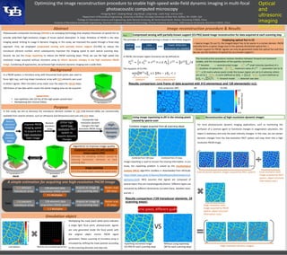
Results comparison (one frame of data acquired with 512 elements(a) and 128 elements(b)~(c)):
Back-projection (BP) BP CS-PKS
Step3 Reconstruction of high-resolution dynamic images
Combine images acquired from all scanning steps:
Combined from 100 steps Combined from 25 steps
Image inpainting is used to recover the missing information. In our
study, the inpainting problem is solved by the morphological
analysis (MCA) algorithm (toolbox is downloaded from MCALab:
https://fadili.users.greyc.fr/demos/WaveRestore/downloads/mcal
ab/Home.html). MCA assumes that signals are composed of
several layers that are morphologically distinct. Different layers are
recovered by different dictionaries (curvelet basis, wavelets basis,
and etc. ).
Results comparison (128 transducer elements, 25
scanning steps):
Inpainting recovered image
(CS-PKS for each scanning step)
Without using inpainting
(BP for each scanning step)
VS
Same speed, different quality!
Step2 Using image inpainting to fill in the missing pixels
caused by sparse scan
…
…
For most photoacoustic dynamic imaging applications, such as monitoring the
perfusion of a contrast agent or functional changes in oxygenation saturation, the
object is stationary and only the pixel intensity changes. In this case, we can extract
dynamic changes from the low-resolution PACT system and map them into a high
resolution PACM image.
(Low resolution dynamic images acquired by PACT system) (Low resolution static
image acquired by PACT
system, object structure
information only.)
(High resolution static
image acquired by PACM
system, object structure
information only.)
(High resolution dynamic images)
Optimizing the image reconstruction procedure to enable high-speed wide-field dynamic imaging in multi-focal
photoacoustic computed microscopy
Optical
and
ultrasonic
imaging
laboratory
Hongying Wana, Depeng Wanga, Jing Mengb, Liang Songc, Leslie Yinga, and Jun Xiaa
aDepartment of Biomedical Engineering, University at Buffalo, the State University of New York, Buffalo, NY, 14260, USA
bCollege of Information Science and Engineering, Qufu Normal University, 80 Yantai Road North, Rizhao, Shandong 276826, China
cInstitute of Biomedical and Health Engineering, Shenzhen Institutes of Advanced Technology, Chinese Academy of Sciences, 1068 Xueyuan Boulevard, Shenzhen 518055, China
512-element
transducer array
128-element data
acquisition (DAQ) system
4:1 Multiplex
Acquire an image at
one scanning step
Raster-scan
100 steps
Original:
Goal: