Selaginella: features, morphology ,anatomy and reproduction.
Lecture No. 02_ Engine.pdf
1. Farm Machinery and Power
Er. Gourav Sahu
Lecture No.2
2.0 Introduction
Heat engine is a machine for converting heat, developed by burning fuel into useful work.
Heat engine is a device which generates thermal energy and transforms it into mechanical
energy. Heat engine is of two types:
(i) External combustion (EC) engine,
(ii) Internal combustion (IC) engine.
2.0.1. External combustion engine: It is the engine designed to generate power from fuel in
which fuel is burn outside the engine cylinder. Here combustion process uses heat in the form
of steam, which is generated in a boiler, placed entirely separate from the working cylinder.
2.0.2. Internal combustion engine (I. C. Engine): It is the engine designed to derive its
power from the fuel, burnt within the engine cylinder. Here combustion of fuel and generation
of heat takes place within the cylinder of the engine.
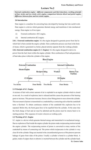
2.1 Principle of I.C. Engine
A mixture of fuel with correct amount of air is exploded in an engine cylinder which is closed
at one end. As a result of explosion, heat is released and this causes the pressure of the burning
gases to increase. This pressure increase, forces a close fitting piston to move down the cylinder.
This movement of piston is transmitted to a crankshaft by a connecting rod so that the crankshaft
turns a flywheel. To obtain continuous rotation of the crankshaft this explosion has to be
repeated. Before this, the burnt gases have to be expelled from the cylinder. At the same time
the fresh charge of fuel and air must be admitted and the piston must be returns back to its
starting position. This sequence of events is known as working cycle.
2.2 Working of I.C. Engine
I.C. engine is a device which generate thermal energy and transmitted it to mechanical energy.
Due to explosion of fuel inside the engine cylinder the piston make reciprocating motion insisde
the engine cylinder. The reciprocating motion of piston is converted to rotary motion of the
crankshaft by means of connecting rod. The piston which reciprocates in the cylinder is very
close fit in the cylinder. Rings are inserted in the circumferential grooves of the piston to prevent
leakage of gases from sides of the piston. Usually a cylinder is bored in a cylinder block. A
gasket, made of copper sheet or asbestos is inserted between the cylinder and the cylinder head.
Internal combustion engine - different components and their functions, working principle
of four stroke and two stroke cycle engine, comparison between diesel and petrol engine,
difference between four and two stroke engine.
2. Farm Machinery and Power
Er. Gourav Sahu
The combustion space is provided at the top of the cylinder head where combustion takes place.
There is a rod called connecting rod for connecting the piston and the crankshaft. A pin called
gudgeon pin or wristpin is provided for connecting the piston and the connecting rod of the
engine. The end of the connecting rod which fits over the gudgeon pin is called small end of the
connecting rod. The other end which fits over the crank pin is called big end of the connecting
rod. The crankshaft rotates in main bearings which are fitted in the crankcase. A flywheel is
provided at one end of the crankshaft for smoothening the uneven torque, produced by the
engine. There is an oil sump at the bottom of the engine which contains lubricating oil for
lubricating different parts of the engine (Fig.1).
Fig. 1. Working components of I.C.Engine
2.3 Engine components
Internal combustion engine consists of the following parts (Fig.2):
Cylinder: It is a part of the engine which confines the expanding gases and forms the
combustion space. It is the basic part of the engine. It provides space in which piston operates
to suck the air or air-fuel mixture. The piston compresses the charge and the gas is allowed to
expand in the cylinder, transmitting power for useful work. Cylinders are usually made of high
grade cast iron.
3. Farm Machinery and Power
Er. Gourav Sahu
Fig. 2.Components of I.C.Engine
Cylinder block: It is the solid casting which includes the cylinder and water jackets (cooling
fins in the air cooled engines).
Cylinder head: It is detachable portion of an engine which covers the cylinder and includes the
combustion chamber, spark plugs and valves.
Cylinder liner or sleeve: It is a cylindrical lining either wet or dry which is inserted in the
cylinder block in which the piston slides. Cylinder liners are fitted in the cylinder bore and they
are easily replaceable. The overhauling and repairing of the engines, fitted with liners is easy
and economical. Liners are classified as: dry liner, and wet liner. Dry liner makes metal to metal
contact with the cylinder block casting. Wet liners come in contact with the cooling water,
whereas dry liners do not come in contact with cooling water.
Piston: It is a cylindrical part closed at one end which maintains a close sliding fit in the engine
cylinder. It is connected to the connecting rod by a piston pin. The force of the expanding gases
against the closed end of the piston, forces the piston down in the cylinder. This causes the
connecting rod to rotate the crankshaft. Cast iron is chosen due to its high compressive strength,
low coefficient of expansion, resistance to high temperature, ease of casting and low cost.
Aluminum and its alloys are preferred mainly due to its lightness.
Head (crown) of piston: It is top of the piston.
Skirt: It is that portion of the piston below the piston pin which is designed to absorb the
side movements of the piston.
Piston ring: It is a split expansion ring, placed in the groove of the piston. Piston rings are fitted
in the grooves, made in the piston. They are usually made of cast iron or pressed steel alloy.
The functions of the ring are as follows:
(a) It forms a gas tight combustion chamber for all positions of piston.
(b) It reduces contact area between cylinder wall and piston wall for preventing friction
losses and excessive wear.
4. Farm Machinery and Power
Er. Gourav Sahu
(c) It controls the cylinder lubrication.
(d) It transmits the heat away from the piston to the cylinder walls. Piston rings are of
two types: (a) Compression ring and (b) Oil ring.
(a) Compression ring. Compression rings are usually plain, single piece and are always
placed in the grooves, nearest to the piston head.
(b) Oil ring. Oil rings are grooved or slotted and are located either in lowest groove above
the piston pin or in a groove above the piston skirt. They control the distribution of lubrication
oil in the cylinder and the piston. They prevent excessive oil consumption also. Oil ring is
provided with small holes through which excess oil returns back to the crankcase chamber.
Piston pin: It is also called wrist pin or gudgeon pin. Piston pin is used to join the connecting
rod to the piston. It provides a flexible or hinge like connection between the piston and the
connecting rod. It is usually made of case hardened alloy steel.
Connecting rod: It is a special type of rod, one end of which is attached to the piston and the
other end to the crankshaft. It transmits the power of combustion to the crankshaft and makes it
rotate continuously. It is usually made of drop forged steel.
Crankshaft: It is the main shaft of an engine which converts the reciprocating motion of the
piston into rotary motion of the flywheel. Usually the crankshaft is made of drop forged steel
or cast steel. The space that supports the crankshaft in the cylinder block is called main journal,
whereas the part to which connecting rod is attached is known as crank journal.
Fly wheel: Fly wheel is made of cast iron. Its main functions are as follows:
(a) It stores energy during power stroke and returns back the same energy during the idle
strokes, providing a uniform rotary motion by virtue of its inertia.
(b) It also carries ring gear that meshes with the pinion of the starting motor.
(c) The rear surface of the flywheel serves as one of the pressure surfaces for the clutch
plate.
(d) Engine timing marks are usually stamped on the flywheel, which helps in adjusting the
timing of the engine.
(e) Some times the flywheel serves the purpose of a pulley for transmitting power.
Crankcase: The crankcase is that part of the engine which supports and encloses the crankshaft
and camshaft. It provides a reservoir for the lubricating oil of the engine.
Cam shaft: It is a shaft which raises and lowers the inlet and exhaust valves at proper time.
Camshaft is driven by crankshaft by means of gears, chains or sprockets. The speed of the
camshaft is exactly half the speed of the crankshaft in four stroke engine. Camshaft operates the
ignition timing mechanism, lubricating oil pump and fuel pump. It is mounted in the crankcase,
parallel to the crankshaft.
Timing gear: Timing gear is a combination of gears, one gear of which is mounted at one end
of the camshaft and other gear on the end of the end of the crankshaft. Camshaft gear is bigger
in size than that of the crankshaft gear and it has twice as many teeth as that of the losing
crankshaft gear. For this reason, this gear is commonly called Half time gear. Timing gear
controls the timing of ignition, timing of opening and closing of valves as well as fuel injection
timing.
5. Farm Machinery and Power
Er. Gourav Sahu
Inlet manifold: It is that part of the engine through which air or air-fuel mixture enters into the
engine cylinder. It is fitted by the side of the cylinder head.
Exhaust manifold: It is that part of the engine through which exhaust gases go out of the engine
cylinder. It is capable of with-standing high temperature of burnt gases. It is fitted by the side
of the cylinder head.
2.4. Cassification of Internal Combustion Engine
Internal combustion engines are classified in two types depending on the period required to
complete a cycle of operation. They are four stroke and two stroke engines.
1. When the cycle is completed in two revolutions of the crankshaft, it is called four stroke
cycle engines.
2. When the cycle is completed in one revolution of the crankshaft, it is called two stroke
cycle engines.
I.C. engines are of two types: (i) Petrol engine (carburetor type, spark ignition engine), and (ii)
diesel engine (compression ignition engine).
Petrol engine: It is the engine, in which liquid fuel is atomized, vaporized and mixed with air
in correct proportion before entering onto the engine cylinder during suction stroke. The fuel is
ignited in the cylinder by an electric spark.
Diesel engine: In this engine, during suction stroke, only air is entered into the cylinder and
compressed. The fuel is injected through fuel injectors and ignited by heat of compression.
2.4.1 Working of four stroke cycle engine
In four stroke cycle engine, all the events taking place inside the engine cylinder are completed
in four strokes of the piston i.e., suction, compression, power and exhaust stroke (Fig.3). This
engine has got valves for controlling the inlet of charge and outlet of exhaust gases. In two
stroke cycle engine, all the events take place in two strokes of the piston.The four strokes of the
piston are as follows:
1. Suction stroke: During this stroke, only air or mixture of air and fuel are drawn inside
the cylinder. The charge enters the engine through inlet valve which remains open during
admission of charge. The exhaust valve remains closed during this stroke. The pressure in
the engine cylinder is less than atmospheric pressure during this stroke.
2. Compression strike: The charge taken in the cylinder is compressed by the piston during
this stroke. The entire charge of the cylinder is compressed to a small volume contained in
the clearance volume of the cylinder. If only air is compressed in the cylinder (as in the case
of diesel engine), the fuel is injected at the end of the compression stroke. The ignition takes
place due to high pressure and temperature. If the mixture of air and fuel is compressed in
the cylinder (as in the case of spark ignition engine i.e., petrol engine), the mixture is ignited
by spark plug. After ignition, tremendous amount of heat is generated, causing very high
pressure in the cylinder which pushes the piston backward for useful work. Both valves are
closed during this stroke.
3. Power stroke: During power stroke, the high pressure developed due to combustion of
6. Farm Machinery and Power
Er. Gourav Sahu
fuel causes the piston to be forced downwards. The connecting rod with the help of
crankshaft transmits the power to the transmission system for useful work. Both valves are
closed during this stroke.
4. Exhaust stroke: Exhaust gases go out through exhaust valves during this stroke. All the
burnt gases go out of the engine and the cylinder becomes ready to receive the fresh charge.
The inlet valve is closed and exhaust valve remains open during this stroke. The exhaust
valve is closed just after the end of the exhaust stroke, and the inlet valve is opened just
before the burning of the suction stroke to repeat the cycle of operation.
Thus it is found that out of four strokes, there is only one power stroke and three idle
strokes. The power stroke supplies necessary momentum for useful work.
Fig. 3. Working of four stroke cycle engine
2.4.2. Working of Two stroke cycle engine
In such engines, the whole sequence of events i.e. suction, compression, power and exhaust are
completed in two strokes of the piston and in one complete revolution of the crankshaft (Fig.4).
There is no valve in this type of engine. Gas movement takes place through holes called ports
in the cylinder. The crankcase of the engine is gas tight in which the crankshaft rotates.
First stroke (suction + compression): When the piston moves up the cylinder, it covers two
of the ports, the exhaust port and the transfer port, which are normally almost opposite to each
other. This traps a charge of fresh mixture in the cylinder and further upward movement of the
piston compresses this charge. Further movement of the piston also uncovers a third port in the
cylinder suction port. More fresh mixture is drawn through this port into the crankcase. Just
before the end of this stroke, the mixture in the cylinder is ignited as in the four stroke cycle
Second stroke (Power + exhaust): The rise in pressure in the cylinder caused by the burning
gases forces the piston to move down the cylinder. When the piston goes down, it covers and
closes the suction port, trapping the mixture drawn into the crankcase during the previous stroke
then compressing it. Further downward movements of the piston uncover first the exhaust port
and then transfer port. This allows the burnt gases to flow out through exhaust port. Also the
fresh mixture under pressure in the crankcase is transferred into the cylinder through transfer
7. Farm Machinery and Power
Er. Gourav Sahu
port during this stroke. Special shaped piston crown deflect the incoming mixture up around the
cylinder so that it can help in driving out the exhaust gases.
When the piston is at the top of its stroke, it is said to be at the top dead centre (TDC).
When the piston is at the bottom of its stroke, it is said to be at its bottom dead centre (BDC).
In two stroke cycle engine, both the sides of the piston are effective, which is not the case in
case of four stroke cycle engine.
Fig. 4. Working of two stroke cycle engine
Scavenging: The process of removal of burnt or exhaust gases from the engine cylinder is
known as scavenging. Entire burnt gases do not go out in normal stroke, hence some type of
blower or compressor is used to remove the exhaust gases in two stroke cycle engine.
8. Farm Machinery and Power
Er. Gourav Sahu
2.5 Comparison between diesel and petrol (carburetor) engines
S.No. Diesel Engine Petrol Engine
1. Diesel fuels are used. Vapourizing fuels such as
petrol, powerine or kerosene are used.
2. Air alone is taken in during suction stroke. Mixture of air and fuel is taken in.
3. Fuel is injected into superheated air of the
combustion space where burning takes
place.
Air-fuel is compressed in the combustion
chamber where it is ignited by an electric
spark.
4. Air-fuel ratio is not constant as the quantity
of air drawn into the cylinder is always the
same. To vary the load and speed the
quantity of fuel injected is changed.
Air and fuel are almost always in the
ratio of 15:1, but to vary the engine
power, quantity of mixture is varied.
5. Compression ratio of the engine varies from
14:1 to 20:1.
Compression ratio of the engine
varies from 5:1 to 8:1.
6. Specific fuel consumption is about 0.2 kg
per BHP per hour.
Specific fuel consumption is about
0.29 kg per BHP per hour.
7. 4.5 litres of fuel is sufficient for nearly 20
hp hour.
4.5 litres of fuel will last about 12 hp
hour.
8. Diesel engine develops more torque, when
it is heavily loaded.
This characteristic is not present in
carburetor engines.
9. Thermal efficiency varies between
32 and 38%.
Thermal efficiency varies between 25
and 32%.
10. It runs at a lower
temperature on part load.
Combustion gas temperature
is slightly higher under
part load.
11. Engine weight per horse power is
high.
Engine weight per horse power is
comparatively low.
12. Initial cost is high. Initial cost is low.
13. Operating cost is low. Operating cost is comparatively high.
9. Farm Machinery and Power
Er. Gourav Sahu
2.6 Comparison between two stroke and four stroke engines
S.No. Particulars Four stroke engine Two stroke engine
1. No. of power stroke one power stroke for every two
revolutions of the crankshaft
one power stroke for each
revolutions of the crankshaft
2. Power for the same
cylinder volume
Small Large (about 1.5 times of 4
stroke)
3. Valve mechanism Present Ports instead of valves
4. Construction and cost Complicated and expensive Simple, cheap
5. Fuel consumption Little High (about 15% more)
6. Removal of exhaust gases Easy Difficult
7. Durability Good Poor
8. Stability of operation High Low
9. Lubrication Equipped withan independent
lubricating oil circuit
Using fuel, mixed with
lubricating oil
10. Oil consumption Little Much
11. Carbon deposit inside
cylinder
Not so much Much because of mixed fuel
12. Noise Suction & exhaust is noiseless,
but other working is noisy
Suction & exhaust is
noiseless, but other
working is noise less
13. Air tight of crankcase Un necessary Must be sealed
14. Cooling Normal Chances of overheating
15. Self weight and size Heavy & large Light & small
2.7 ADVANTAGES AND DISADVANTAGES OF TWO-STROKE CYCLE OVER
FOUR-STROKE CYCLE ENGINES
Advantages:
1. The two-stroke cycle engine gives one working stroke for each revolution of the crankshaft.
Hence theoretically the power developed for the same engine speed and cylinder volume is
twice that of the four-stroke cycle engine, which gives only one working stroke for every
two revolutions of the crankshaft. However, in practice, because of poor scavenging, only
50-60% extra power is developed.
10. Farm Machinery and Power
Er. Gourav Sahu
2. Due to one working stroke for each revolution of the crankshaft, the turning moment on the
crankshaft is more uniform. Therefore, a two-stroke engine requires a lighter flywheel.
3. The two-stroke engine is simpler in construction. The design of its ports is much simpler
and their maintenance easier than that of the valve mechanism.
4. The power required to overcome frictional resistance of the suction and exhaust strokes is
saved, resulting in some economy of fuel.
5. Owing to the absence of the cam, camshaft, rockers, etc. of the valve mechanism, the
mechanical efficiency is higher.
6. The two-stroke engine gives fewer oscillations.
7. For the same power, a two-stroke engine is more compact and requires less space than a
four-stroke cycle engine. This makes it more suitable for use in small machines and
motorcycles.
8. A two-stroke engine is lighter in weight for the same power and speed especially when the
crankcase compression is used.
9. Due to its simpler design, it requires fewer spare parts.
10. A two-stroke cycle engine can be easily reversed if it is of the valve less type.
Disadvantages:
1. The scavenging being not very efficient in a two-stroke engine, the dilution of the charges
takes place which results in poor thermal efficiency.
2. The two-stroke spark ignition engines do not have a separate lubrication system and
normally, lubricating oil is mixed with the fuel. This is not as effective as the lubrication of
a four-stroke engine. Therefore, the parts of the two-stroke engine are subjected to greater
wear and tear.
3. In a spark ignition two-stroke engine, some of the fuel passes directly to the exhaust. Hence,
the fuel consumption per horsepower is comparatively higher.
4. With heavy loads a two-stroke engine gets heated up due to the excessive heat produced. At
the same time the running of the engine is riot very smooth at light loads.
5. It consumes more lubricating oil because of the greater amount of heat generated.
6. Since the ports remain open during the upward stroke, the actual compression starts only
after both the inlet and exhaust ports have been closed. Hence, the compression ratio of this
engine is lower than that of a four-stroke engine of the same dimensions. As the efficiency
of an engine is directly proportional to its compression ratio, the efficiency of a two-stroke
cycle engine is lower than that of a four-stroke cycle engine of the same size