
Recommended
Recommended
More Related Content
What's hot
What's hot (20)
Similar to Evolution of valves, Identification & Key Features | IACTS SCORE 2020
Similar to Evolution of valves, Identification & Key Features | IACTS SCORE 2020 (20)
More from IACTSWeb
More from IACTSWeb (8)
Recently uploaded
Recently uploaded (20)
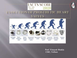
Evolution of valves, Identification & Key Features | IACTS SCORE 2020
- 1. Prof. Vinayak Shukla CMC, Vellore
- 2. Valve replacement surgery has a long, important and very inspiring history.
- 3. Faultless valve function is essential for the graceful forward movement of blood
- 4. A valve prosthesis which is ‘safer than the condition it corrects’, remains a mirage. Failures fail to frustrate The spirit refuses to die, Enthusiasm scents triumph at the very next step As efforts continue unabated. We shall not cease from exploration and the end of all our exploring Will be to arrive where we started and know the place for the first time. Elliots lines.
- 5. It must not propagate emboli It must be chemically inert and not damage blood It must offer no resistance to physiological flows It must close promptly, i.e. less than 0.05 second It must remain closed during the appropriate phase of the cardiac cycle
- 6. It must have lasting physical and geometric features It must be inserted in a physiological site (generally the normal anatomical site) It must be capable of permanent fixation It must not annoy the patient It must be technically practical to insert
- 7. Dr. Charles Hufnagel Implanted an acrylic ball valve prosthesis into the descending aorta of a 30-year-old woman for aortic incompetence in 1952 at Georgetown Medical Center in Washington, DC, who could lead a normal life after the surgery It was a methylcrylate chamber containing the methylcrylaye ball in the middle, which was "implanted quickly into the descending aorta using a nonsuture technique."
- 8. More than 200 implanted Hufnagel valves functioned for as long as 30 years with no significant wear. No anticoagulation was used. The drawback to this model, besides the mortality and cumbersome insertion during the brief cross- clamp period, was that patients could hear the plastic ball bouncing around inside them.
- 9. His work proved that biocompatible materials could be successfully used to create heart valves, but his problem was placing it where it had to work. Not the descending thoracic aorta.
- 10. 1950- HUFNAGEL developed a ball valve,designed to be placed in the descending thoracic aorta for aortic insufficiency Acrylic ball inserted into the descending aorta
- 11. As the valve only prevented the regurgitant flow from the lower body,the cardiac work was not much improved Embolisation and thrombosis frequently occurred Extremely noisy
- 12. A biologically compatible material A hemodynamically tolerant design
- 13. With the development of the heart- lung machine and the opportunity to work within the open heart Dr Harken working with Mr W. C. Birtwell at Davol, Inc, developed a ball valve with a double cage fabricated of stainless steel Implanted in 17 patients initially, of which only two could survive. Both the patients required successive valve replacements .
- 14. Albert Starr, a physician, and Lowell Edwards, an electrical engineer, simplified the caged-ball valve using a single titanium cage, a silastic ball, and a sewing ring covered with Teflon. The Starr-Edwards valve was first implanted in the mitral position in 1960, and later in the aortic position. The valve became commercially available in 1965.
- 15. In the early 1960s, Dr George Magovern, Sr, Chief of Cardiothoracic Surgery at the University of Pittsburgh Medical Center, working with an engineer, Mr Harry Cromie, developed a ball valve that incorporated a unique method of sutureless fixation It was inserted by rotating an implantation tool to engage the multiple vertical pins in the aortic annulus and was particularly suited for aortic implantation
- 16. In 1989, Dr Magovern reported on his 25-year experience with the Magovern-Cromie aortic valve His valve was implanted in 728 patients between 1962 and 1988.
- 17. This ball valve was the first prosthetic valve to employ the “full-flow” orifice concept. This was achieved by a double set of cages permitting the silicone elastomer ball to rest on the smaller inflow cage during valve closure. In 1989 at the World Congress on Valve replacement, San Diego, Dr. Smeloff reported that 50,000 Smeloff valves had been implanted worldwide, with no structural failure for 22 years of use.
- 18. This ball valve was the first prosthetic valve to employ the ‘full flow’ orifice concept. The ball rests on the smaller inflow cage during valve closure. This has now referred to has the ………….
- 20. This valve was developed by Dr Michael DeBakey and Harry Cromie of Surgitool and was introduced in 1967. In 1969, the polyethylene poppet was replaced with a hollow pyrolytic carbon poppet. This was the first use of a new carbon material developed by Dr Jack Bokros at the General Atomic Company in LaJolla, California.
- 21. The fabrication of a hollow ball of pyrolytic carbon (pyrolyte) for the DeBakey-Surgitool valve in 1969 by the materials engineer Dr Jack Bokros was a landmark in mechanical valve development . Bokros’ pyrolytic carbon, originally developed for the encapsulation of nuclear fuel rods, would become over the next decade, the principal biomaterial for virtually all new mechanical valves
- 22. Carbon – pyrolytic carbon, oringally used to cover nuclear fuel rods, and now has become the principal bio material for virtually all mechanical valves. Dr Bokros found that highly polished pyrolytic carbon will not bond with heparin but is the most thrombo resistant non heparinised material that they have ever evaluated.
- 23. Kay-Shiley Disc Valve Dr Jerome Kay and Mr Donald Shiley designed the first disc valve that achieved worldwide use beginning in 1965. Reliable mitral prosthesis that utilized a stellite housing and a flat silicone elastomer disc Unfortunately, there were problems with wear of the silicone elastomer disc and it was replaced with a Delrin polymer disc in 1975
- 24. Bjork-Shiley Flat Disc Valve (also designated as standard or spherical disc valve) was extremely successful worldwide, with nearly 300,000 aortic and mitral prostheses implanted between 1969 and 1986 Bjork-Shiley Convexo-Concave Tilting Disc Valve . By making a concave pyrolyte disc and modifying the inlet and outlet struts, the disc could slide forward and down about 2 mm, thus achieving the desired enlargement of the lesser valve orifice.
- 25. The inlet and outlet struts were modified such that the disc could make a slide forward and down movement for about 2 mm, thereby achieving the desired enlargement of the valve orifice. And also a better wash of the entire console with the forward flow of blood. This was very stictly followed in the Medtronic Hall valves.
- 26. The design of the valve, comprised a unique tilting prolyte disc with a small central perforation for a thin metal strut that guides the disc during opening and closing of the valve
- 27. Dr Victor Hall and Robert Kaster developed this valve, and hence was known as Hall Kaster valve. Once the Medtronic company took over manufacturing this valve was then known as Medtronic Hall and then later on as Medtronic valve.
- 28. Just after the era of tilting disc models, the bi-leaflet heart valve model was introduced. The valves usually consist of two semicircular leaflets that rotate about struts attached to the valve housing. The design of the valve was such that it resulted in a greater effective orifice area Gott-Daggett Bileaflet Valve was the very first model of bileaflet design and was introduced in the late 1960s.
- 29. Dr Bhagabant Kalke from India went to work with DR Lillehei. Common sense : he had observed the passive tidal floodgates that opened with the outgoing tide and closed with the incoming tide to protect shore line crops. So he came up with a bi leaflet valve with peripheral hinges and a central opening.
- 31. Doctor Bhagabant Kalke came from India to work in Dr Lillehei’s laboratory in 1964. Doctor Kalke had grown up on the west coast of India and was familiar with the passive tidal floodgates that opened with the outgoing tide and closed with the incoming tide to protect shoreline crops.
- 32. Doctor Kalke fabricated a polymer valve in Dr Lillehei’s laboratory based on the configuration of the Indian tidal floodgates with peripheral hinging leaflets and a central opening.
- 33. Why bi leaflet design – to provide a low profile valve than the bulky caged ball. So what happened - The disadvantage was that there was relatively stagnant blood flow in the area of the struts used to hold the leaflets. Thrombus formation took place here. And so what had to be done. What did he do ???
- 34. The pivot sites for the leaflets were placed at the equator of the annular ring. And the problem could be overcome. Then came Robert Kaster who removed the over riding struts.
- 35. St Jude Medical Bi leaflet valve came into being. Mr Manny Villafana Mr Xinon Posis Dr Demetre Nicoloff They too designed a similar valve with pivots near the periphery and a central opening.
- 36. Mr Donal Hanson redesigned the valve with the hinge mechanism located near the central axis of the housing. Also, the concept of a leaflet – tab rotating in a ‘butterfly recess’ in the inner wall of the housing. Mr Villafan - the entire valve made or Mr Bokros’ pyrolytic carbon.
- 37. Why this name ? Not even a single name from the ones who contributed to this valve. Why not Nicoloff valve. Mr Villafana’s son was recovering from a serious illness. St Jude Thaddeus is the patron saint of difficult times they believed. And that is how the name came.
- 38. And that is how this SJM valve came into being. The non rotatable series, had its own difficulties. The Master series came, which were rotatable. And then for some time we had silver impregnated sewing rings, which were withdrawn. And then the Regent valve came.
- 39. Improved effective orifice area By reducing the sewing ring thickness, shifting the carbon rim to the supra annular position and improving the rotation mechanism
- 40. In 1986, Dr Bokros created the Carbomedics bileaflet valve, which was similar to the St. Jude valve, but its housing could be rotated within the sewing ring Doctor Bokros and Mr Villafana also developed the two other valves (On-X and ATS respectively)
- 41. The solid pyrolytic carbon valve has a unique pivot design pivot areas were entirely within the orifice ring differs from other valves - that have cavities in the hinge area. the open pivot design is intended to decrease blood stasis and thrombus formation valve design minimizes overall valve height and generates a larger orifice area.
- 42. Approved by FDA in 2002 Pure pyrolytic carbon used in On X valve is stronger than silicon alloyed pyrolytic carbon used in other mecahnical valves.
- 43. The inflow has a flared inlet designed to reduce flow turbulence. Flared inlet produces higher volume of flow with increased washing to minimize flow stagnation. The outflow rim consists of leaflet guards designed to protect the leaflets while in closed position. The leaflets rotate around tabs located within the inner circumference of the orifice ring.
- 44. In closed position each leaflet forms an angle of 40 degrees relative to the pane of the orifice. In open position the plane of each leaflet forms a nominal angle of 90 degrees relative to the plane of the orifice. The leaflets have to travel an arc of 50 degrees to the closed position.
- 45. Leaflets open 90 degrees with soft landing leaflets designed to reduce the blood element stress Comes in sizes 23 to 33mm
- 46. Question ?? How this sizing has been done for ON X valve ?
- 47. Size 25 has an effective orifice area of 2.02 sq cms. And all the valves have the same area, only the sewing cuff changes.
- 48. Developed in Sri Chitra Institute in Trivandrum and first implanted in December 1990. M. S Valiathan was the surgeon who was the main force behind the development of the Chitra valve The current valve is the 4 th generation valve.
- 49. The first model had a titanium housing with welded strut and a Delrin disc. The housing and struts were then machined from a block of Haynes -25 coated with titanium nitride and the occluder was from a single crystal of synthetic sapphire The final model has Haynes -25 housing and a highly polished, cryo-machined solid state disc manufactured from ultra high molecular weight polyethylene. The sewing ring is made from a knitted polyester fabric.
- 50. DELRIN® (Acetal Homopolymer) DELRIN® is a crystalline plastic which offers an excellent balance of properties that bridge the gap between metals and plastics. DELRIN® possesses high tensile strength, creep resistance and toughness. It also exhibits low moisture absorption.
- 51. More than 75000 have been implanted. It is a tilting disc valve. The Chitra tilting disc valve has an integrally machined cobalt- based alloy cage- Haynes metal, an ultra-high molecular-weight polyethylene disc, and a polyester suture ring.
- 53. The label of mechanical and biological heart valves always consists of the trade name and a number indicating the valve size (in millimeters) This valve size represents the outer diameter of the valve housing/stent tissue annulus diameter(TAD, in millimeters) The Internal orifice diameter(IOD) of the valve is smaller than the labeled valve size.
- 54. Hemodynamically, the most important parameter of both mechanical valves and bioprostheses is their effective orifice area (EOA)
- 55. Geometric orifice area is the whole inner area of the valve including the area occupied by the opened discs or leaflets, struts, and other mechanisms of the valve. By subtracting the area of opening components of the valve from GOA, the so-called Clear orifice area (COA) is obtained The EOA is that portion of the valve orifice area through which the blood really flows. The EOA is usually one quarter or one third smaller than GOA
- 56. In a given patient, the most important parameter is the indexed value ( IEOA), i.e., EOA related to 1 m2 of the patient’s body surface. It has to be kept in mind that values declared by the manufacturer used to look more optimistic (in vitro values) than post-implantation echocardiography values calculated on the basis of continuity equation (in vivo values).
- 57. The aim is to implant a valve large enough to avoid hemodynamically significant patient–prosthesis mismatch (PPM). The original paper that described valve prosthesis–patient mismatch (VP–PM)stated that “Mismatch can be considered to be present when the effective prosthetic heart valve area, after insertion into the patient, is less than that of a normal human valve”; all prosthetic heart valves (PHVs) are smaller than normal and thus are inherentlyc stenotic S.H. RahimtoolaThe problem of valve prosthesis-patient mismatch Circulation, 58 (1978), pp. 20-24
- 58. It is important mainly in the aortic position where IEOA of the implanted valve should be greater than 0.85 cm2/m2. In the mitral valve the cut-off value for PPM is considered to be 1.2 cm2/m2. Severe patient–prosthesis mismatch occurs if IEOA is less than 0.65 cm2/m2 in the aortic position and less than 0.9 cm/m2 in the mitral position
- 59. Internal orifice diameter(IOD) Tissue annulus diameter(TAD) External sewing ring diameter(ESRD)
- 60. Stented bioprosthesis have inherent gradients because the actual valve is supported by a stent and housing material The EFFECTIVE ORIFICE AREA(EOA) refers to the true cross sectional area through which the blood must flow(most important parameter) EOA=SV/VTI Cross sectional area of the valve(Gorlin’s formula) A=Q/(44.3*sq.root of pressure gradient)
- 74. Thank you for your attention and time.