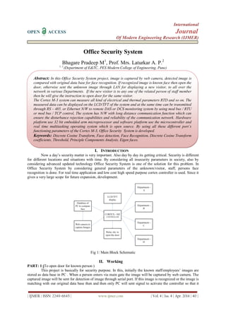
Office Security System
•
1 like•474 views

This document describes an office security system that uses face recognition for access control. It involves the following: 1) Capturing images of visitors using a web camera and comparing the images to a database of authorized employees' faces using discrete cosine transform coefficients and Euclidean distance calculations to identify matches. 2) If a match is found, a signal is sent to open the door. Otherwise, the unknown image is transmitted over LAN to staff for identification and potential door opening. 3) An LPC1768 cortex microcontroller is used to control door access and transmit images over LAN due to its processing power and communication capabilities. The system provides contactless security access control for offices.
![Office Security System.......
| IJMER | ISSN: 2249–6645 | www.ijmer.com | Vol. 4 | Iss. 4 | Apr. 2014 | 41 |
will switch ON the relay of Motor. This will open the door. Thus the door will open for known staff/ persons
only.
Fig 2: Flowchart
PART: 2 (Face Detection & Recognition part )[1, 2, 3]
Block Diagram with Explanation
Fig.3 : Block Diagram of Face detection
The captured image by web camera is compared with the original data base which is already stored in
PC. Now the process of face recognition is done. The captured image is resized in (200*180) predefined format.
The RGB image is converted in to gray image. Apply the discrete cosine transform on this gray scale image. We
do not required all the frequency components of complete face but only the high frequencies are required. After
applying DCT only high frequency components get separate out i.e. only the face borders. Out of these
frequency components only few which are required for Euclidian distance are picked up for comparison with
original data base. If this Euclidian distance is less than threshold then the face is identified or it indicates that is
face of known person i.e. face matching.
Give the instruction for controller to open the door. Thus due to the real time application and to reduce
processing time of processor. Only required Frequency components are taken for consideration of Euclidian
distance calculations.
INPUT
IMAGE
RESIZE
AND
CONVER
T TO
GREY
FEATURE
EXTRACTI
ON
(DCT
Coefficients)
ADD TO
DATABA
SE](data:image/gif;base64,R0lGODlhAQABAIAAAAAAAP///yH5BAEAAAAALAAAAAABAAEAAAIBRAA7)
Recommended
More Related Content
What's hot
What's hot (20)
Viewers also liked
Viewers also liked (20)
Similar to Office Security System
Similar to Office Security System (20)
More from IJMER
More from IJMER (20)
Recently uploaded
Recently uploaded (20)
Office Security System
- 1. International OPEN ACCESS Journal Of Modern Engineering Research (IJMER) | IJMER | ISSN: 2249–6645 | www.ijmer.com | Vol. 4 | Iss. 4 | Apr. 2014 | 40 | Office Security System Bhagare Pradeep M1 , Prof. Mrs. Laturkar A. P.2 1, 2 (Department of E&TC, PES Modern College of Engineering, Pune) I. INTRODUCTION Now a day’s security matter is very important. Also day by day its getting critical. Security is different for different locations and situations with time. By considering all insecurity parameters in society, also by considering advanced updated technology Office Security System is one of the solution for this problem. In Office Security System by considering general parameters of the unknown/visitor, staff, persons face recognition is done. For real time application and low cost high speed purpose cortex controller is used. Since it gives a very large scope for future expansion, development. Fig 1: Main Block Schematic II. Working PART: 1 (To open door for known person ) This project is basically for security purpose. In this, initially the known staff/employees’ images are stored as data base in PC . When a person enters via main gate the image will be captured by web camera. The captured image will be sent for detection of image through serial port. If this image is recognized or the image is matching with our original data base then and then only PC will sent signal to activate the controller so that it Abstract: In this Office Security System project, image is captured by web camera, detected image is compared with original data base for face recognition. If recognized image is known face then open the door, otherwise sent the unknown image through LAN for displaying a new visitor, to all over the network in various Departments. If the new visitor is to any one of the related person of staff member then he will give the instruction to open door for the same visitor. The Cortex M-3 system can measure all kind of electrical and thermal parameters RTD and so on. The measured data can be displayed on the LCD/TFT of the system and at the same time can be transmitted through RS – 485, or Ethernet N/W to remote DAS or DCS monitoring system by using mod bus / RTU or mod bus / TCP control, The system has N/W with long distance communication function which can ensure the disturbance rejection capabilities and reliability of the communication network. Hardware platform use 32 bit embedded arm microprocessor and software platform use the microcontroller and real time multitasking operating system which is open source. By using all these different port’s functioning parameters of the Cortex M-3, Office Security System is developed. Keywords: Discrete Cosine Transform, Face detection, Face Recognition, Discrete Cosine Transform coefficients, Threshold, Principle Components Analysis, Eigen faces.
- 2. Office Security System....... | IJMER | ISSN: 2249–6645 | www.ijmer.com | Vol. 4 | Iss. 4 | Apr. 2014 | 41 | will switch ON the relay of Motor. This will open the door. Thus the door will open for known staff/ persons only. Fig 2: Flowchart PART: 2 (Face Detection & Recognition part )[1, 2, 3] Block Diagram with Explanation Fig.3 : Block Diagram of Face detection The captured image by web camera is compared with the original data base which is already stored in PC. Now the process of face recognition is done. The captured image is resized in (200*180) predefined format. The RGB image is converted in to gray image. Apply the discrete cosine transform on this gray scale image. We do not required all the frequency components of complete face but only the high frequencies are required. After applying DCT only high frequency components get separate out i.e. only the face borders. Out of these frequency components only few which are required for Euclidian distance are picked up for comparison with original data base. If this Euclidian distance is less than threshold then the face is identified or it indicates that is face of known person i.e. face matching. Give the instruction for controller to open the door. Thus due to the real time application and to reduce processing time of processor. Only required Frequency components are taken for consideration of Euclidian distance calculations. INPUT IMAGE RESIZE AND CONVER T TO GREY FEATURE EXTRACTI ON (DCT Coefficients) ADD TO DATABA SE
- 3. Office Security System....... | IJMER | ISSN: 2249–6645 | www.ijmer.com | Vol. 4 | Iss. 4 | Apr. 2014 | 42 | Fig.4: Flow chart for face recognition Fig. 5: Block diagram to Calculate Euclidian Distance Fig. 6: Block diagram to Calculate DCT coefficients [Courtesy: IEEE images]
- 4. Office Security System....... | IJMER | ISSN: 2249–6645 | www.ijmer.com | Vol. 4 | Iss. 4 | Apr. 2014 | 43 | III. Calculation Calculation of Euclidian Distance:[2, 4] D = √[ 𝑓0 − 𝑣0 2 + 𝑓1 − 𝑣1 2 + … . . . + 𝑓𝑚 −1 − 𝑣 𝑚 −1 2 ] where v = [v0, v1, v2 , . . . . . 𝑣 𝑚 −1 ] T = In put image DCT coefficient vector f = [f0, f1, f2, f3 . . . . . 𝑓𝑚 −1 ] T = DCT coefficients vector of image to be compared. After calculating the Euclidian distance the match is found on the basis of the shortest Euclidian distance in data base. Fig.7: Block diagram to Calculate Eigen faces PART: 3 Controller (LPC 1768) & LAN [5] If the visitor/unknown persons want to enter through Main-gate. The image will be captured by web camera. The image sent to the data base for comparison of face, and reply of the controller will be not matching of face. In such case, the image will be transferred to departmental LAN which is connected to cortex controller. Thus unknown person will seen on the screen of departmental PC. Thus you can see the face of the unknown visitor who is stood in front of the security gate which is far away from the different departments. Thus we can capture, stored the unknown visitors image for our information. If identity or introduction of image or photo copy of this unknown person is matched to any of the dept’s / staff member then that person will convey to security dept. to open the door / main gate. Thus door will not open for unknown person and unknown person will not be allowed to enter without identity is the major part of controller. Technical Features of LPC 1768 1. ARM Cortex-M3 processor, running at frequencies of up to 100 MHz A Memory Protection Unit (MPU) supporting eight regions is included. And available as 100-pin LQFP package. 2. ARM Cortex-M3 built-in Nested Vectored Interrupt Controller (NVIC). 3. Up to 512 kB on-chip flash programming memory. Enhanced flash memory accelerator 4. Enables high-speed 100 MHz operation with zero wait states. 5. In-System Programming (ISP) and In-Application Programming (IAP) via on-chip Boot loader software. 6. On-chip SRAM includes: 7. 32/16 kB of SRAM on the CPU with local code/data bus for high-performance CPU access. 8. Two/one 16 kB SRAM blocks with separate access paths for higher throughput. These SRAM blocks may be used for Ethernet (LPC1768/66/64 only), USB, and DMA memory, as well as for general purpose CPU instruction and data storage. 9. Eight channel General Purpose DMA controller (GPDMA) on the AHB multilayer matrix that can be used with the SSP, I2S-bus, UART, the Analog-to-Digital and Digital-to-Analog converter peripherals, timer match signals, and for memory-to-memory transfers. 10. Multilayer AHB matrixes interconnect provides a separate bus for each AHB master. AHB masters include the CPU, General Purpose DMA controller, Ethernet MAC (LPC1768/66/64 only), and the USB interface. This interconnect provides communication with no arbitration delays. 11. Split APB bus allows high throughput with few stalls between the CPU and DMA. 12. Serial interfaces: 13. Ethernet MAC with RMII interface and dedicated DMA controller (LPC1768/66/64 only). 14. USB 2.0 full-speed device/Host/OTG controller with dedicated DMA controller and on-chip PHY for device, Host, and OTG functions. The LPC1764 includes a device controller only. 15. Four UARTs with fractional baud rate generation, internal FIFO, DMA support, and RS-485 support. One UART has modem control I/O, and one UART has IrDA support.
- 5. Office Security System....... | IJMER | ISSN: 2249–6645 | www.ijmer.com | Vol. 4 | Iss. 4 | Apr. 2014 | 44 | Fig. 8: Block schematic of LPC 1768 16. CAN 2.0B controller with two channels. 17. SPI controller with synchronous, serial, full duplex communication and programmable data length. 18. Two SSP controllers with FIFO and multi-protocol capabilities. The SSP interfaces can be used with the GPDMA controller. 19. Two I2C-bus interfaces supporting fast mode with a data rate of 400 Kbits/s with multiple address recognition and monitor mode. 20. One I2C-bus interface supporting full I2C-bus specification and fast mode plus with a data rate of 1 Mbit/s with multiple address recognition and monitor mode. 21. On the LPC1768/66/65 only, I2S (Inter-IC Sound) interface for digital audio input or output, with fractional rate control. The I2S-bus interface can be used with the GPDMA. The I2S-bus interface supports 3-wire and 4-wire data transmit and receive as well as master clock input/output. 22. Other peripherals: 23. 70 General Purpose I/O (GPIO) pins with configurable pull-up/down resistors and a new, configurable open-drain operating mode. 24. 12-bit Analog-to-Digital Converter (ADC) with input multiplexing among eight pins, conversion rates up to 1 MHz, and multiple result registers. The 12-bit ADC can be used with the GPDMA controller. 25. 10-bit Digital-to-Analog Converter(DAC) with dedicated conversion timer and DMA support (LPC1768/66/65 only). 26. Four general purpose timers/counters, with a total of eight capture inputs and ten compare outputs. Each timer block has an external count input and DMA support. 27. One motor control PWM with support for three-phase motor control. 28. Quadrature encoder interface that can monitor one external quadrature encoder. 29. One standard PWM/timer block with external count input. 30. RTC with a separate power domain and dedicated RTC oscillator. The RTC block includes 64 bytes of battery-powered backup registers.
- 6. Office Security System....... | IJMER | ISSN: 2249–6645 | www.ijmer.com | Vol. 4 | Iss. 4 | Apr. 2014 | 45 | 31. Watchdog Timer (WDT) resets the microcontroller within a reasonable amount of time if it enters an erroneous state. System tick timer, including an external clock input option. 32. Repetitive interrupt timer provides programmable and repeating timed interrupts. 33. Each peripheral has its own clock divider for further power savings. 34. Standard JTAG test/debug interface for compatibility with existing tools. Serial Wire Debug and Serial Wire Trace Port options. 35. Emulation trace module enables non- intrusive, high-speed real-time tracing of instruction execution. 36. Integrated PMU (Power Management Unit) automatically adjusts internal regulators to minimize power consumption during Sleep, Deep sleep, Power-down, and Deep Power-down modes. 37. Four reduced power modes: Sleep, Deep-sleep, Power-down, and Deep power-down. 38. Single 3.3 V power supply (2.4 V to 3.6 V). 39. Four external interrupt inputs configurable as edge/level sensitive. All pins on PORT0 and PORT2 can be used as edge sensitive interrupt sources. 40. Non - mask able Interrupt (NMI) input. IV. Conclusions Cortex M-3 (LPC 1768) is an universal controller with the help of this we can perform or interface all kind of modern devices and perform different applications as per requirements. In Office Security System, using different communication port, image is transferred for face recognition. The unknown image is transferred for identification for all departments through LAN port. The decision of opening door is completely controlled by Cortex M-3 controller with the help of predefined programmed criteria. Thus intelligent Office Security System will be achieved with the help of Cortex M-3 controller. V. Future Work 1) We can modify this for Iris detection. 2) We can modify this for Metal detection. 3) We can modify this for Finger print detection. 4) If our controller is connected to Police Stations then unknown image will be compared with WANTED person’s images and system will give information of WANTED persons to police stations automatically. Thus system will help for security of the society. REFERENCES [1] DerzuOmaia, JanKees v. d. Poel, Leonardo V. Batista”Low – Memory Requirement and Efficient Face Recognition System Based on DCT Pyramid”, IEEE Transations on Consumer Electronics, Vol. 56. 3, August 2010. [2] DerzuOmaia, JanKees v. d. Poel, Leonardo V. Batista,” 2D- DCT Distance Based Face Recognition Using Reduced Number of Coefficents ”, October 11-October 15 2009 IEEE International Conference on DCT Page(s) 1-8. Rio de Janeiro, Brazil. [3] Shah Ronak, Venkat Reddy, Rahul kumar Mishra, Tamakuwala Jimmy B. ,”Fingerprint Rccognition using Discrete Cosine Transform”, November 2009 [4] Swarup Ku. Dandpat, Sukadev Meher, “ New Technique for DCT-PCA Based Face Recognition”, IEEE International Conference On DCT – PCA, 2009. [5] S.R. Shridhara, Di Renzo, S. Lingum, S. J. Lee, R. Blazquze, , J. Maxey, S. Ghanem, Y. H. Lee, R. Abdalla, P. Singh and M. Goel, “ Microwatt Embedded Processor platform for medical System on chip applications,” IEEE Symp. VLSI Circuits Dig. Paper 15-16, 2010