SlideShare a Scribd company logo
1 of 9
Download to read offline
Unit 8: Optical Amplifiers and Networks
 All optical amplifiers increase the power level of incident light through a stimulated emission or an
optical power transfer process.
 The basic operation of a generic optical amplifier is shown in Fig. below
 The device absorbs energy supplied from an external source called pump.
 The pump supplies energy to electrons in an active medium which raises them to higher energy
levels to produce population inversion.
 An incoming signal photon will trigger these excited electrons to drop to lower levels through a
stimulated emission process and emits photons of equal energy. The result is an amplified optical
signal.
Basic Applications and Types of Optical Amplifiers:
 Optical amplifiers have found widespread use in diverse application ranging from ultra-long
undersea links to short links in access networks.
General Applications:
Fig. below shows the following three general applications
 In-line optical amplifiers
o In a single mode link the effects of fiber dispersion is small.
o In such a link complete regeneration of the signal is not necessary and simple amplification
of the optical signal is sufficient.
o Thus, an in-line amplifier can be used to compensate for transmission loss and increase the
distance between regenerative repeaters.
 Pre-amplifier
o It is a front end amplifier for an optical receiver.
o A weak optical signal is amplified before photodetection to increase signal to noise ratio.
o Compared with other front-end devices such as APD or heterodyne detectors, an optical pre-
amplifier provides a large gain factor and broader bandwidth.
 Power Amplifier
o Also called booster amplifier includes placing the device immediately after an optical
transmitter to boost the transmitted power.
o This increases the transmission distance by 10-100km and compensate for coupler insertion
loss and power splitting loss.
o Fig. shows an example for boosting the optical signal in front of a passive star coupler.
Amplifier Types
 Semiconductor Optical Amplifiers (SOAs)
o Alloys of semiconductor materials from groups III and V make up active medium
for SOAs.
o They work in O-band and C-band and can be integrated on the same substrate as
other optical devices.
o Compared with DFAs they consume less electrical power, have fewer components
and are more compact.
o The rapid gain response give rise to crosstalk effects when a broad spectrum of
wavelengths must be amplified.
 Active fiber or doped fiber amplifiers (DFAs)
o The active medium is created by lightly doping silica or tellurite fiber core with rare
earth elements such as thulium, erbium.
o They operate in S, C, L bands.
o They have the ability to pump devices at several wavelengths and possess low
coupling loss for the given fiber transmission medium.
o They are immune from interference effects between different optical channels.
 Raman amplifiers.
o A fiber based Raman amplifier uses stimulated Raman scattering (SRS) occurring in
silica fibers when an intense pump beam propagates through it.
o The incident pump photon gives up its energy to create another photon of reduced
energy at lower frequency. The remaining energy is absorbed by the medium in the
form of molecular vibrations. Thus Raman amplifiers must be pumped optically to
provide gain.
o Fig. shows how a fiber can be used as a Raman amplifier.
o The pump and the signal beams at frequencies s and p are injected into the
fiber through a fiber coupler.
o The energy is transferred from the pump beam to signal beam through SRS as
the two beams co-propagate inside the fiber.
o The pump and the signal beams counter-propagate in the backward pumping
configuration commonly used in practice.
Erbium doped fiber amplifiers (EDFA):
 A silica fiber doped with erbium, is known as erbium doped fiber amplifier and is popular material
for long haul telecommunication applications.
 The operation of a standard EDFA normally is limited to the 1530 to 1560nm region.
Application mechanism:
 Simplified energy level diagram and various transition processes of Er3+
ions in silica is shown in
Fig. below
 The various energy transitions and photon emission ranges are as follows-
o The pump band shown in the top left of Fig. exists at 1.27ev separation from the bottom of
the 4
I15/2 ground state. This energy corresponds to a 980nm wavelength.
o The top of the 4
I13/2 metastable band is separated from the bottom of the 4
I15/2 ground state
band by 0.841eV. this energy corresponds to 1480nm wavelength.
o The bottom of the 4
I13/2 metastable band is separated from the bottom of the 4
I15/2 ground
state band by 0.814eV. This energy corresponds to 1530nm wavelength.
o The bottom of the 4
I13/2metastable band is separated from the top of the 4
I15/2 ground state
band by 0.775eV. This energy corresponds to 1600nm wavelength.
 The pump wavelengths are 980nm and 1480nm. The photons emitted during transitions of electrons
between possible energy levels in the metastable and ground state bands can range from 1530nm to
1600nm.
 The operation is as follows-
o Process 1: A pump lase emitting 980nm photons is used to excite ions from the ground state
to the pump level.
o Process 2: These excited ions decay very quickly from the pump band to the metastable
band. During this decay the excess energy is released as phonons.
o Process 3: Another possible pump wavelength is 1480nm. The absorption of a 1480nm pump
photon excites an electron from the ground state directly to the lightly populated top of
metastable level.
o Process 4: These electrons then tend to move down to the more populated lower end of the
metastable level.
o Process 5: Some of the ions sitting at the metastable level can decay back to the ground state
in the absence of externally stimulating photon flux. This decay is known as spontaneous
emission.
o Process 6: When a flux of signal photons that have energies corresponding to band-gap
energy between ground state and metastable level passes through the device a small portion
of external photons will be absorbed by ions in the ground state, which raises these ions to
the metastable level.
o Process 7: In the stimulated emission a signal photon triggers an excited ion to drop to the
ground state, thereby emitting a new photon of same energy, wave-vector and polarization as
the incoming signal photon. The emission range is 1530-1560nm.
 Fig above gives an example for Ge-doped silica glass that has Al co-dopants. The Al helps to absorb
Er ions in the glass and they broaden the amplifier gain spectrum.
 Beyond 1560nm the gain decreases steadily until it reaches 0 dB at around 1616nm.
EDFA Architecture:
a. Co-directional pumping:
o The pump light is injected from the same direction as the signal flow.
o This gives better noise performance.
b. Counter-directional pumping:
o The pump light is injected in the opposite direction to the signal flow.
o It allows higher gains.
c. Dual pumping:
o Pump Light is injected from both directions of the signal flow.
o The typical gain is +35dB.
SONET/SDH:
 In digital time division multiplexing (TDM) scheme, a standard signal format called synchronous
optical network (SONET) in North America and synchronous hierarchy (SDH) in other parts of the
world was introduced.
Transmission Formats and Speeds:
 Fig. below shows the basic structure of a SONET frame.
 This is a two dimensional structure consisting of 90 columns by 9 rows of bytes.
 In standard SONET technology, a section connects adjacent pieces of equipment, a line is a longer
link that connects two SONET devices, and a path is a complete end to end connection.
 The first three columns comprise transport overhead bytes that carry network management
information.
 The remaining field of 87 columns is called the synchronous payload envelope (SPE) and carries
user data plus nine bytes of path overhead (POH). The POH supports performance monitoring by end
equipment, status, signal labeling, etc. The POH are always in one column and can be located
anywhere in SPE.
 The fundamental SONET frame has 125 s duration. Thus, the transmission bit rate of the basic
SONET signal is 51.84Mbps. This is called STS-1 signal where STS stands for synchronous
transport signal.
 An STS-N signal has a transmission rate equal to Nx51.84Mbps.
 In SDH the basic rate is equivalent to STS-3 or 155.52Mbps. This is called synchronous transport
module-level 1 (STM-1). Higher rates are designated by STM-M.
 For values of N greater than 1, the columns of the frame becomes N times wider, with the number of
rows remaining at nine.
 STS-3 frame is 270 columns wide with first nine columns containing overhead information and the
next 261 columns being payload data.
 An STM-N frame has 125micro-sec duration and consists of nine rows, each of which has length
270xN bytes.
SONET/SDH Rings:
 A key characteristic of SONET/SDH is that they are configured as either ring or mesh architecture.
This is done to create loop diversity for un-interrupted service protection purposes in case of link or
equipment failures. They are also called self-healing rings.
 The following two architectures have become popular for SONET and SDH networks
o Two fiber, unidirectional, path switched ring ( two fiber UPSR)
o Two fiber or four fiber, bi-directional, line switched ring ( two or four fiber BLSR)
 Fig. below shows a two fiber unidirectional path switched ring network.
 In a unidirectional ring the normal traffic travels clockwise around the ring, on the primary path. For
e.g. the connection from node 1 to node 3 uses link 1 and 2, whereas the traffic from node 3 to node
1 traverses links 3 and 4.
 The counterclockwise path is used as an alternate route for protection against link or node failures.
This protection path is indicated by dashed lines.
 To achieve protection, the signal from a transmitting node is dual-fed into both primary and
protection fibers. This establishes a designated protection path on which traffic flows
counterclockwise: namely, from node 1 to node 3 via links 5 and 6 as shown in Fig. above.
 Fig below illustrates the architecture of a four fiber bidirectional line switched ring.
 Here, the two primary fiber loops are used for normal bidirectional communication and the two other
secondary fiber loops are standby links for protection purposes.
 The four-fiber BLSR has a capacity advantage since it uses twice as much fiber cabling and because
traffic between two nodes is sent only partially around the ring. To see this consider the connection
between nodes 1 and 3. The traffic from node 1 to 3 flows in a clockwise direction along links 1p
and 2p. In the return path the traffic flows counterclockwise from node 3 to node 1 along links 7p
and 8p.
 To see the function of the standby link in the four-fiber BLSR, consider first the case where the
transmitter or receiver circuit used on the primary link fails in either node 3 or 4. In this situation, the
affected nodes detect a loss of signal condition and switch both primary fibers connecting these
nodes to the secondary protection pair.
 The exact same reconfiguration scenario will occur when the primary fiber connecting nodes 3 and 4
breaks.
High Speed Light-wave Links:
 A new challenge emerge in the development of high speed optical transceivers operating at higher
rates such as 10, 40, and 160 Gbps
I. Links operating at 10Gbps:
 These include Fiber Channel connections for storage area networks, 10-gigabit Ethernet lines for
local area and metro networks and SONET/SDH terrestrial and undersea long haul lines and metro
links.
 As a result of product development efforts several multimode fibers with different bandwidth grades
exists for 10-Gbps use. They are
o OM1 grade fiber is used with LEDs. The bandwidth of these fibers is 200 MHz-km at
850nm and 500MHz-km at 1310nm.
o OM2 grade fiber is used to send 1-Gbps signals at 850nm over about 750m distances and
10Gbps over 82m.
o OM3 grade fiber has the highest bandwidth and can support 10Gbps data rates over distances
up to 300m
II. Links operating at 160 Gbps
 Systems that can operate at 160Gbps over a single wavelength were installed using standard G.652
single mode fibers.
 These links use the concept of optical time division multiplexing to form 160Gbps data stream.
 The bit interleaved OTDM multiplexing technique is similar to WDM.
III. Links operating at 40 Gbps
 New challenges in terms of transceiver response characteristics, chromatic dispersion control and
polarization mode dispersion compensation arise when transitioning to higher capacity links such as
40Gbps data rates.
 For example, compared to 10Gbps system, using a conventional on-off keying modulation format a
link operating at 40Gbps is sixteen times more sensitive to chromatic dispersion, four times more
sensitive to polarization mode dispersion.
 Therefore alternate modulation schemes such as binary differential phase shift keying (DPSK) are
employed.
OFC notes Unit -8 VTU

More Related Content

What's hot

Microwave Engineering Lecture Notes
Microwave Engineering Lecture NotesMicrowave Engineering Lecture Notes
Microwave Engineering Lecture NotesFellowBuddy.com
 
Multiplexing anddemultiplexing
Multiplexing anddemultiplexingMultiplexing anddemultiplexing
Multiplexing anddemultiplexingTania Sahito
 
Dense wavelength division multiplexing
Dense wavelength division multiplexingDense wavelength division multiplexing
Dense wavelength division multiplexingBise Mond
 
Routing in telephone networks
Routing in telephone networksRouting in telephone networks
Routing in telephone networksRenjith Ravi
 
Chapter 7 multiple access techniques
Chapter 7 multiple access techniquesChapter 7 multiple access techniques
Chapter 7 multiple access techniquesKaushal Kabra
 
LED & LASER sources of light
LED & LASER sources of lightLED & LASER sources of light
LED & LASER sources of lightRohit Singh
 
Wavelength division multiplexing
Wavelength division multiplexingWavelength division multiplexing
Wavelength division multiplexingNalin Dubey
 
2.2 frequency division multiple access
2.2   frequency division multiple access2.2   frequency division multiple access
2.2 frequency division multiple accessJAIGANESH SEKAR
 
Large scale path loss 1
Large scale path loss 1Large scale path loss 1
Large scale path loss 1Vrince Vimal
 
What is Mode Field Diameter?
What is Mode Field Diameter?What is Mode Field Diameter?
What is Mode Field Diameter?Caroline Connolly
 
Phase modulation
Phase modulationPhase modulation
Phase modulationavocado1111
 

What's hot (20)

Microwave Engineering Lecture Notes
Microwave Engineering Lecture NotesMicrowave Engineering Lecture Notes
Microwave Engineering Lecture Notes
 
Multiplexing anddemultiplexing
Multiplexing anddemultiplexingMultiplexing anddemultiplexing
Multiplexing anddemultiplexing
 
Sdh concept
Sdh conceptSdh concept
Sdh concept
 
Dense wavelength division multiplexing
Dense wavelength division multiplexingDense wavelength division multiplexing
Dense wavelength division multiplexing
 
carrier synchronization
carrier synchronizationcarrier synchronization
carrier synchronization
 
Routing in telephone networks
Routing in telephone networksRouting in telephone networks
Routing in telephone networks
 
Chapter 7 multiple access techniques
Chapter 7 multiple access techniquesChapter 7 multiple access techniques
Chapter 7 multiple access techniques
 
LED & LASER sources of light
LED & LASER sources of lightLED & LASER sources of light
LED & LASER sources of light
 
WDM Basics
WDM BasicsWDM Basics
WDM Basics
 
Receivers
ReceiversReceivers
Receivers
 
Wavelength division multiplexing
Wavelength division multiplexingWavelength division multiplexing
Wavelength division multiplexing
 
2.2 frequency division multiple access
2.2   frequency division multiple access2.2   frequency division multiple access
2.2 frequency division multiple access
 
Large scale path loss 1
Large scale path loss 1Large scale path loss 1
Large scale path loss 1
 
Microwave link budget
Microwave link budgetMicrowave link budget
Microwave link budget
 
What is Mode Field Diameter?
What is Mode Field Diameter?What is Mode Field Diameter?
What is Mode Field Diameter?
 
Gunn Diode
Gunn Diode Gunn Diode
Gunn Diode
 
Magic tee
Magic tee  Magic tee
Magic tee
 
satellite communication- UNIT-III.pptx
satellite communication- UNIT-III.pptxsatellite communication- UNIT-III.pptx
satellite communication- UNIT-III.pptx
 
Multiple Access
Multiple AccessMultiple Access
Multiple Access
 
Phase modulation
Phase modulationPhase modulation
Phase modulation
 

Viewers also liked

Mutual coupling
Mutual couplingMutual coupling
Mutual couplingJagadish M
 
Optical Amplifier and Networks
Optical Amplifier and NetworksOptical Amplifier and Networks
Optical Amplifier and NetworksJagadish M
 
4Sem VTU-HDL Programming Notes-Unit3-Behavioral Descriptions
4Sem VTU-HDL Programming Notes-Unit3-Behavioral Descriptions4Sem VTU-HDL Programming Notes-Unit3-Behavioral Descriptions
4Sem VTU-HDL Programming Notes-Unit3-Behavioral DescriptionsDr. Shivananda Koteshwar
 
Introduction to metamaterials
Introduction to metamaterialsIntroduction to metamaterials
Introduction to metamaterialsJagadish M
 
Optical fiber communication (Unit 6) notes written by Spoorti Arun Kumar (AP,...
Optical fiber communication (Unit 6) notes written by Spoorti Arun Kumar (AP,...Optical fiber communication (Unit 6) notes written by Spoorti Arun Kumar (AP,...
Optical fiber communication (Unit 6) notes written by Spoorti Arun Kumar (AP,...Arunkumar Gowdru
 
Blue Brain Seminar Report
Blue Brain Seminar ReportBlue Brain Seminar Report
Blue Brain Seminar ReportVarun A M
 
Optical Source - Light Emitting Diodes
Optical Source - Light Emitting DiodesOptical Source - Light Emitting Diodes
Optical Source - Light Emitting DiodesFatiha Akma
 
Optical fiber communication Part 2 Sources and Detectors
Optical fiber communication Part 2 Sources and DetectorsOptical fiber communication Part 2 Sources and Detectors
Optical fiber communication Part 2 Sources and DetectorsMadhumita Tamhane
 
Optical Fiber Sources And Detectors
Optical Fiber Sources And DetectorsOptical Fiber Sources And Detectors
Optical Fiber Sources And DetectorsAziz Zoaib
 
Hyperloop VTU Seminar Report
Hyperloop VTU Seminar ReportHyperloop VTU Seminar Report
Hyperloop VTU Seminar ReportUmar Ahmed
 
optical fibre ppt for download visit http://nowcracktheworld.blogspot.in/
optical fibre  ppt for download visit http://nowcracktheworld.blogspot.in/optical fibre  ppt for download visit http://nowcracktheworld.blogspot.in/
optical fibre ppt for download visit http://nowcracktheworld.blogspot.in/Ram Niwas Bajiya
 
Dc Choppers
Dc ChoppersDc Choppers
Dc Choppersstooty s
 

Viewers also liked (16)

Final ofc ppt
Final ofc pptFinal ofc ppt
Final ofc ppt
 
Mutual coupling
Mutual couplingMutual coupling
Mutual coupling
 
COMMUNICATION LED
COMMUNICATION LEDCOMMUNICATION LED
COMMUNICATION LED
 
8th ec & te dec 2014
8th ec & te dec 20148th ec & te dec 2014
8th ec & te dec 2014
 
Optical Amplifier and Networks
Optical Amplifier and NetworksOptical Amplifier and Networks
Optical Amplifier and Networks
 
4Sem VTU-HDL Programming Notes-Unit3-Behavioral Descriptions
4Sem VTU-HDL Programming Notes-Unit3-Behavioral Descriptions4Sem VTU-HDL Programming Notes-Unit3-Behavioral Descriptions
4Sem VTU-HDL Programming Notes-Unit3-Behavioral Descriptions
 
Introduction to metamaterials
Introduction to metamaterialsIntroduction to metamaterials
Introduction to metamaterials
 
Optical fiber communication (Unit 6) notes written by Spoorti Arun Kumar (AP,...
Optical fiber communication (Unit 6) notes written by Spoorti Arun Kumar (AP,...Optical fiber communication (Unit 6) notes written by Spoorti Arun Kumar (AP,...
Optical fiber communication (Unit 6) notes written by Spoorti Arun Kumar (AP,...
 
Blue Brain Seminar Report
Blue Brain Seminar ReportBlue Brain Seminar Report
Blue Brain Seminar Report
 
Optical Source - Light Emitting Diodes
Optical Source - Light Emitting DiodesOptical Source - Light Emitting Diodes
Optical Source - Light Emitting Diodes
 
Optical fiber communication Part 2 Sources and Detectors
Optical fiber communication Part 2 Sources and DetectorsOptical fiber communication Part 2 Sources and Detectors
Optical fiber communication Part 2 Sources and Detectors
 
Optical Fiber Sources And Detectors
Optical Fiber Sources And DetectorsOptical Fiber Sources And Detectors
Optical Fiber Sources And Detectors
 
Hyperloop VTU Seminar Report
Hyperloop VTU Seminar ReportHyperloop VTU Seminar Report
Hyperloop VTU Seminar Report
 
Structures of led
Structures of ledStructures of led
Structures of led
 
optical fibre ppt for download visit http://nowcracktheworld.blogspot.in/
optical fibre  ppt for download visit http://nowcracktheworld.blogspot.in/optical fibre  ppt for download visit http://nowcracktheworld.blogspot.in/
optical fibre ppt for download visit http://nowcracktheworld.blogspot.in/
 
Dc Choppers
Dc ChoppersDc Choppers
Dc Choppers
 

Similar to OFC notes Unit -8 VTU

12 gain flattening in erbium doped fiber amplifier based optical communicatio...
12 gain flattening in erbium doped fiber amplifier based optical communicatio...12 gain flattening in erbium doped fiber amplifier based optical communicatio...
12 gain flattening in erbium doped fiber amplifier based optical communicatio...Arun K Mohan
 
Introduction to optical amplifiers
Introduction to optical amplifiersIntroduction to optical amplifiers
Introduction to optical amplifiersVanessa Shen
 
Fianl Year Project Report
Fianl Year Project ReportFianl Year Project Report
Fianl Year Project ReportShruti Nadkarni
 
Comparatively analysis of Erbium Doped Fibre Amplifier for Fibre Communication
Comparatively analysis of Erbium Doped Fibre Amplifier for Fibre CommunicationComparatively analysis of Erbium Doped Fibre Amplifier for Fibre Communication
Comparatively analysis of Erbium Doped Fibre Amplifier for Fibre CommunicationIJERD Editor
 
Design of a 600 mhz ddipole antenna
Design of a 600 mhz ddipole antennaDesign of a 600 mhz ddipole antenna
Design of a 600 mhz ddipole antennaSabrina Chowdhury
 
A simple high capability c+ l broad bandwidth erbium doped fiber source
A simple high capability c+ l broad bandwidth erbium doped fiber sourceA simple high capability c+ l broad bandwidth erbium doped fiber source
A simple high capability c+ l broad bandwidth erbium doped fiber sourceNaku Technology Co,. Ltd
 
Advance in optical fiber amplifier
Advance in optical fiber amplifierAdvance in optical fiber amplifier
Advance in optical fiber amplifiersan456987
 
Analyzing the Different Parameters of Dipole Antenna
Analyzing the Different Parameters of Dipole AntennaAnalyzing the Different Parameters of Dipole Antenna
Analyzing the Different Parameters of Dipole AntennaIJEEE
 
Comparison among fiber amplifiers
Comparison among fiber amplifiersComparison among fiber amplifiers
Comparison among fiber amplifiersSaimunur Rahman
 
A simple high capability c+ l broad bandwidth erbium doped fiber source
A simple high capability c+ l broad bandwidth erbium doped fiber sourceA simple high capability c+ l broad bandwidth erbium doped fiber source
A simple high capability c+ l broad bandwidth erbium doped fiber sourceNaku Technology Co,. Ltd
 
Role antennas play in a MIMO link - paper
Role antennas play in a MIMO link - paperRole antennas play in a MIMO link - paper
Role antennas play in a MIMO link - paperAndre Fourie
 
A glimpse of fractal antenna design
A glimpse of fractal antenna designA glimpse of fractal antenna design
A glimpse of fractal antenna designSreekar Rompicharla
 
An Overview of EDFA Gain Flattening by Using Hybrid Amplifier
An Overview of EDFA Gain Flattening by Using Hybrid AmplifierAn Overview of EDFA Gain Flattening by Using Hybrid Amplifier
An Overview of EDFA Gain Flattening by Using Hybrid AmplifierIJEEE
 
Optical amplifiers and networking
Optical amplifiers and networking Optical amplifiers and networking
Optical amplifiers and networking Amogha Bandrikalli
 

Similar to OFC notes Unit -8 VTU (20)

Fiber Optics.pptx
Fiber Optics.pptxFiber Optics.pptx
Fiber Optics.pptx
 
12 gain flattening in erbium doped fiber amplifier based optical communicatio...
12 gain flattening in erbium doped fiber amplifier based optical communicatio...12 gain flattening in erbium doped fiber amplifier based optical communicatio...
12 gain flattening in erbium doped fiber amplifier based optical communicatio...
 
Introduction to optical amplifiers
Introduction to optical amplifiersIntroduction to optical amplifiers
Introduction to optical amplifiers
 
Performance Analysis of Different Linearly Polarized Modes for Two Channel MD...
Performance Analysis of Different Linearly Polarized Modes for Two Channel MD...Performance Analysis of Different Linearly Polarized Modes for Two Channel MD...
Performance Analysis of Different Linearly Polarized Modes for Two Channel MD...
 
Fianl Year Project Report
Fianl Year Project ReportFianl Year Project Report
Fianl Year Project Report
 
Comparatively analysis of Erbium Doped Fibre Amplifier for Fibre Communication
Comparatively analysis of Erbium Doped Fibre Amplifier for Fibre CommunicationComparatively analysis of Erbium Doped Fibre Amplifier for Fibre Communication
Comparatively analysis of Erbium Doped Fibre Amplifier for Fibre Communication
 
Design of a 600 mhz ddipole antenna
Design of a 600 mhz ddipole antennaDesign of a 600 mhz ddipole antenna
Design of a 600 mhz ddipole antenna
 
A simple high capability c+ l broad bandwidth erbium doped fiber source
A simple high capability c+ l broad bandwidth erbium doped fiber sourceA simple high capability c+ l broad bandwidth erbium doped fiber source
A simple high capability c+ l broad bandwidth erbium doped fiber source
 
antenna book.pdf
antenna book.pdfantenna book.pdf
antenna book.pdf
 
Advance in optical fiber amplifier
Advance in optical fiber amplifierAdvance in optical fiber amplifier
Advance in optical fiber amplifier
 
Analyzing the Different Parameters of Dipole Antenna
Analyzing the Different Parameters of Dipole AntennaAnalyzing the Different Parameters of Dipole Antenna
Analyzing the Different Parameters of Dipole Antenna
 
Comparison among fiber amplifiers
Comparison among fiber amplifiersComparison among fiber amplifiers
Comparison among fiber amplifiers
 
A simple high capability c+ l broad bandwidth erbium doped fiber source
A simple high capability c+ l broad bandwidth erbium doped fiber sourceA simple high capability c+ l broad bandwidth erbium doped fiber source
A simple high capability c+ l broad bandwidth erbium doped fiber source
 
Lab manual
Lab manualLab manual
Lab manual
 
Role antennas play in a MIMO link - paper
Role antennas play in a MIMO link - paperRole antennas play in a MIMO link - paper
Role antennas play in a MIMO link - paper
 
opsahu advanced communication lab 6 sem.file r.k.r govt poly janjgir
opsahu advanced communication lab 6 sem.file r.k.r govt poly janjgiropsahu advanced communication lab 6 sem.file r.k.r govt poly janjgir
opsahu advanced communication lab 6 sem.file r.k.r govt poly janjgir
 
A glimpse of fractal antenna design
A glimpse of fractal antenna designA glimpse of fractal antenna design
A glimpse of fractal antenna design
 
An Overview of EDFA Gain Flattening by Using Hybrid Amplifier
An Overview of EDFA Gain Flattening by Using Hybrid AmplifierAn Overview of EDFA Gain Flattening by Using Hybrid Amplifier
An Overview of EDFA Gain Flattening by Using Hybrid Amplifier
 
Optical amplifiers and networking
Optical amplifiers and networking Optical amplifiers and networking
Optical amplifiers and networking
 
7 4-1-7-11
7 4-1-7-117 4-1-7-11
7 4-1-7-11
 

Recently uploaded

Introduction-To-Agricultural-Surveillance-Rover.pptx
Introduction-To-Agricultural-Surveillance-Rover.pptxIntroduction-To-Agricultural-Surveillance-Rover.pptx
Introduction-To-Agricultural-Surveillance-Rover.pptxk795866
 
Gfe Mayur Vihar Call Girls Service WhatsApp -> 9999965857 Available 24x7 ^ De...
Gfe Mayur Vihar Call Girls Service WhatsApp -> 9999965857 Available 24x7 ^ De...Gfe Mayur Vihar Call Girls Service WhatsApp -> 9999965857 Available 24x7 ^ De...
Gfe Mayur Vihar Call Girls Service WhatsApp -> 9999965857 Available 24x7 ^ De...srsj9000
 
IVE Industry Focused Event - Defence Sector 2024
IVE Industry Focused Event - Defence Sector 2024IVE Industry Focused Event - Defence Sector 2024
IVE Industry Focused Event - Defence Sector 2024Mark Billinghurst
 
Risk Assessment For Installation of Drainage Pipes.pdf
Risk Assessment For Installation of Drainage Pipes.pdfRisk Assessment For Installation of Drainage Pipes.pdf
Risk Assessment For Installation of Drainage Pipes.pdfROCENODodongVILLACER
 
Call Us ≽ 8377877756 ≼ Call Girls In Shastri Nagar (Delhi)
Call Us ≽ 8377877756 ≼ Call Girls In Shastri Nagar (Delhi)Call Us ≽ 8377877756 ≼ Call Girls In Shastri Nagar (Delhi)
Call Us ≽ 8377877756 ≼ Call Girls In Shastri Nagar (Delhi)dollysharma2066
 
Instrumentation, measurement and control of bio process parameters ( Temperat...
Instrumentation, measurement and control of bio process parameters ( Temperat...Instrumentation, measurement and control of bio process parameters ( Temperat...
Instrumentation, measurement and control of bio process parameters ( Temperat...121011101441
 
Architect Hassan Khalil Portfolio for 2024
Architect Hassan Khalil Portfolio for 2024Architect Hassan Khalil Portfolio for 2024
Architect Hassan Khalil Portfolio for 2024hassan khalil
 
Call Girls Narol 7397865700 Independent Call Girls
Call Girls Narol 7397865700 Independent Call GirlsCall Girls Narol 7397865700 Independent Call Girls
Call Girls Narol 7397865700 Independent Call Girlsssuser7cb4ff
 
Comparative Analysis of Text Summarization Techniques
Comparative Analysis of Text Summarization TechniquesComparative Analysis of Text Summarization Techniques
Comparative Analysis of Text Summarization Techniquesugginaramesh
 
Sachpazis Costas: Geotechnical Engineering: A student's Perspective Introduction
Sachpazis Costas: Geotechnical Engineering: A student's Perspective IntroductionSachpazis Costas: Geotechnical Engineering: A student's Perspective Introduction
Sachpazis Costas: Geotechnical Engineering: A student's Perspective IntroductionDr.Costas Sachpazis
 
CCS355 Neural Networks & Deep Learning Unit 1 PDF notes with Question bank .pdf
CCS355 Neural Networks & Deep Learning Unit 1 PDF notes with Question bank .pdfCCS355 Neural Networks & Deep Learning Unit 1 PDF notes with Question bank .pdf
CCS355 Neural Networks & Deep Learning Unit 1 PDF notes with Question bank .pdfAsst.prof M.Gokilavani
 
Past, Present and Future of Generative AI
Past, Present and Future of Generative AIPast, Present and Future of Generative AI
Past, Present and Future of Generative AIabhishek36461
 
Introduction to Machine Learning Unit-3 for II MECH
Introduction to Machine Learning Unit-3 for II MECHIntroduction to Machine Learning Unit-3 for II MECH
Introduction to Machine Learning Unit-3 for II MECHC Sai Kiran
 
CCS355 Neural Network & Deep Learning Unit II Notes with Question bank .pdf
CCS355 Neural Network & Deep Learning Unit II Notes with Question bank .pdfCCS355 Neural Network & Deep Learning Unit II Notes with Question bank .pdf
CCS355 Neural Network & Deep Learning Unit II Notes with Question bank .pdfAsst.prof M.Gokilavani
 
Application of Residue Theorem to evaluate real integrations.pptx
Application of Residue Theorem to evaluate real integrations.pptxApplication of Residue Theorem to evaluate real integrations.pptx
Application of Residue Theorem to evaluate real integrations.pptx959SahilShah
 
complete construction, environmental and economics information of biomass com...
complete construction, environmental and economics information of biomass com...complete construction, environmental and economics information of biomass com...
complete construction, environmental and economics information of biomass com...asadnawaz62
 

Recently uploaded (20)

Introduction-To-Agricultural-Surveillance-Rover.pptx
Introduction-To-Agricultural-Surveillance-Rover.pptxIntroduction-To-Agricultural-Surveillance-Rover.pptx
Introduction-To-Agricultural-Surveillance-Rover.pptx
 
🔝9953056974🔝!!-YOUNG call girls in Rajendra Nagar Escort rvice Shot 2000 nigh...
🔝9953056974🔝!!-YOUNG call girls in Rajendra Nagar Escort rvice Shot 2000 nigh...🔝9953056974🔝!!-YOUNG call girls in Rajendra Nagar Escort rvice Shot 2000 nigh...
🔝9953056974🔝!!-YOUNG call girls in Rajendra Nagar Escort rvice Shot 2000 nigh...
 
Gfe Mayur Vihar Call Girls Service WhatsApp -> 9999965857 Available 24x7 ^ De...
Gfe Mayur Vihar Call Girls Service WhatsApp -> 9999965857 Available 24x7 ^ De...Gfe Mayur Vihar Call Girls Service WhatsApp -> 9999965857 Available 24x7 ^ De...
Gfe Mayur Vihar Call Girls Service WhatsApp -> 9999965857 Available 24x7 ^ De...
 
IVE Industry Focused Event - Defence Sector 2024
IVE Industry Focused Event - Defence Sector 2024IVE Industry Focused Event - Defence Sector 2024
IVE Industry Focused Event - Defence Sector 2024
 
Risk Assessment For Installation of Drainage Pipes.pdf
Risk Assessment For Installation of Drainage Pipes.pdfRisk Assessment For Installation of Drainage Pipes.pdf
Risk Assessment For Installation of Drainage Pipes.pdf
 
Call Us ≽ 8377877756 ≼ Call Girls In Shastri Nagar (Delhi)
Call Us ≽ 8377877756 ≼ Call Girls In Shastri Nagar (Delhi)Call Us ≽ 8377877756 ≼ Call Girls In Shastri Nagar (Delhi)
Call Us ≽ 8377877756 ≼ Call Girls In Shastri Nagar (Delhi)
 
Instrumentation, measurement and control of bio process parameters ( Temperat...
Instrumentation, measurement and control of bio process parameters ( Temperat...Instrumentation, measurement and control of bio process parameters ( Temperat...
Instrumentation, measurement and control of bio process parameters ( Temperat...
 
Architect Hassan Khalil Portfolio for 2024
Architect Hassan Khalil Portfolio for 2024Architect Hassan Khalil Portfolio for 2024
Architect Hassan Khalil Portfolio for 2024
 
Call Us -/9953056974- Call Girls In Vikaspuri-/- Delhi NCR
Call Us -/9953056974- Call Girls In Vikaspuri-/- Delhi NCRCall Us -/9953056974- Call Girls In Vikaspuri-/- Delhi NCR
Call Us -/9953056974- Call Girls In Vikaspuri-/- Delhi NCR
 
Call Girls Narol 7397865700 Independent Call Girls
Call Girls Narol 7397865700 Independent Call GirlsCall Girls Narol 7397865700 Independent Call Girls
Call Girls Narol 7397865700 Independent Call Girls
 
Comparative Analysis of Text Summarization Techniques
Comparative Analysis of Text Summarization TechniquesComparative Analysis of Text Summarization Techniques
Comparative Analysis of Text Summarization Techniques
 
Sachpazis Costas: Geotechnical Engineering: A student's Perspective Introduction
Sachpazis Costas: Geotechnical Engineering: A student's Perspective IntroductionSachpazis Costas: Geotechnical Engineering: A student's Perspective Introduction
Sachpazis Costas: Geotechnical Engineering: A student's Perspective Introduction
 
CCS355 Neural Networks & Deep Learning Unit 1 PDF notes with Question bank .pdf
CCS355 Neural Networks & Deep Learning Unit 1 PDF notes with Question bank .pdfCCS355 Neural Networks & Deep Learning Unit 1 PDF notes with Question bank .pdf
CCS355 Neural Networks & Deep Learning Unit 1 PDF notes with Question bank .pdf
 
POWER SYSTEMS-1 Complete notes examples
POWER SYSTEMS-1 Complete notes  examplesPOWER SYSTEMS-1 Complete notes  examples
POWER SYSTEMS-1 Complete notes examples
 
Past, Present and Future of Generative AI
Past, Present and Future of Generative AIPast, Present and Future of Generative AI
Past, Present and Future of Generative AI
 
Introduction to Machine Learning Unit-3 for II MECH
Introduction to Machine Learning Unit-3 for II MECHIntroduction to Machine Learning Unit-3 for II MECH
Introduction to Machine Learning Unit-3 for II MECH
 
CCS355 Neural Network & Deep Learning Unit II Notes with Question bank .pdf
CCS355 Neural Network & Deep Learning Unit II Notes with Question bank .pdfCCS355 Neural Network & Deep Learning Unit II Notes with Question bank .pdf
CCS355 Neural Network & Deep Learning Unit II Notes with Question bank .pdf
 
9953056974 Call Girls In South Ex, Escorts (Delhi) NCR.pdf
9953056974 Call Girls In South Ex, Escorts (Delhi) NCR.pdf9953056974 Call Girls In South Ex, Escorts (Delhi) NCR.pdf
9953056974 Call Girls In South Ex, Escorts (Delhi) NCR.pdf
 
Application of Residue Theorem to evaluate real integrations.pptx
Application of Residue Theorem to evaluate real integrations.pptxApplication of Residue Theorem to evaluate real integrations.pptx
Application of Residue Theorem to evaluate real integrations.pptx
 
complete construction, environmental and economics information of biomass com...
complete construction, environmental and economics information of biomass com...complete construction, environmental and economics information of biomass com...
complete construction, environmental and economics information of biomass com...
 

OFC notes Unit -8 VTU

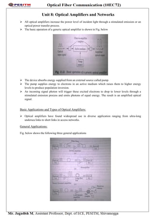
  • 1. Unit 8: Optical Amplifiers and Networks  All optical amplifiers increase the power level of incident light through a stimulated emission or an optical power transfer process.  The basic operation of a generic optical amplifier is shown in Fig. below  The device absorbs energy supplied from an external source called pump.  The pump supplies energy to electrons in an active medium which raises them to higher energy levels to produce population inversion.  An incoming signal photon will trigger these excited electrons to drop to lower levels through a stimulated emission process and emits photons of equal energy. The result is an amplified optical signal. Basic Applications and Types of Optical Amplifiers:  Optical amplifiers have found widespread use in diverse application ranging from ultra-long undersea links to short links in access networks. General Applications: Fig. below shows the following three general applications
  • 2.  In-line optical amplifiers o In a single mode link the effects of fiber dispersion is small. o In such a link complete regeneration of the signal is not necessary and simple amplification of the optical signal is sufficient. o Thus, an in-line amplifier can be used to compensate for transmission loss and increase the distance between regenerative repeaters.  Pre-amplifier o It is a front end amplifier for an optical receiver. o A weak optical signal is amplified before photodetection to increase signal to noise ratio. o Compared with other front-end devices such as APD or heterodyne detectors, an optical pre- amplifier provides a large gain factor and broader bandwidth.  Power Amplifier o Also called booster amplifier includes placing the device immediately after an optical transmitter to boost the transmitted power. o This increases the transmission distance by 10-100km and compensate for coupler insertion loss and power splitting loss. o Fig. shows an example for boosting the optical signal in front of a passive star coupler. Amplifier Types  Semiconductor Optical Amplifiers (SOAs) o Alloys of semiconductor materials from groups III and V make up active medium for SOAs. o They work in O-band and C-band and can be integrated on the same substrate as other optical devices. o Compared with DFAs they consume less electrical power, have fewer components and are more compact. o The rapid gain response give rise to crosstalk effects when a broad spectrum of wavelengths must be amplified.  Active fiber or doped fiber amplifiers (DFAs) o The active medium is created by lightly doping silica or tellurite fiber core with rare earth elements such as thulium, erbium. o They operate in S, C, L bands. o They have the ability to pump devices at several wavelengths and possess low coupling loss for the given fiber transmission medium. o They are immune from interference effects between different optical channels.  Raman amplifiers. o A fiber based Raman amplifier uses stimulated Raman scattering (SRS) occurring in silica fibers when an intense pump beam propagates through it. o The incident pump photon gives up its energy to create another photon of reduced energy at lower frequency. The remaining energy is absorbed by the medium in the form of molecular vibrations. Thus Raman amplifiers must be pumped optically to provide gain.
  • 3. o Fig. shows how a fiber can be used as a Raman amplifier. o The pump and the signal beams at frequencies s and p are injected into the fiber through a fiber coupler. o The energy is transferred from the pump beam to signal beam through SRS as the two beams co-propagate inside the fiber. o The pump and the signal beams counter-propagate in the backward pumping configuration commonly used in practice. Erbium doped fiber amplifiers (EDFA):  A silica fiber doped with erbium, is known as erbium doped fiber amplifier and is popular material for long haul telecommunication applications.  The operation of a standard EDFA normally is limited to the 1530 to 1560nm region. Application mechanism:  Simplified energy level diagram and various transition processes of Er3+ ions in silica is shown in Fig. below  The various energy transitions and photon emission ranges are as follows- o The pump band shown in the top left of Fig. exists at 1.27ev separation from the bottom of the 4 I15/2 ground state. This energy corresponds to a 980nm wavelength. o The top of the 4 I13/2 metastable band is separated from the bottom of the 4 I15/2 ground state band by 0.841eV. this energy corresponds to 1480nm wavelength. o The bottom of the 4 I13/2 metastable band is separated from the bottom of the 4 I15/2 ground state band by 0.814eV. This energy corresponds to 1530nm wavelength. o The bottom of the 4 I13/2metastable band is separated from the top of the 4 I15/2 ground state band by 0.775eV. This energy corresponds to 1600nm wavelength.
  • 4.  The pump wavelengths are 980nm and 1480nm. The photons emitted during transitions of electrons between possible energy levels in the metastable and ground state bands can range from 1530nm to 1600nm.  The operation is as follows- o Process 1: A pump lase emitting 980nm photons is used to excite ions from the ground state to the pump level. o Process 2: These excited ions decay very quickly from the pump band to the metastable band. During this decay the excess energy is released as phonons. o Process 3: Another possible pump wavelength is 1480nm. The absorption of a 1480nm pump photon excites an electron from the ground state directly to the lightly populated top of metastable level. o Process 4: These electrons then tend to move down to the more populated lower end of the metastable level. o Process 5: Some of the ions sitting at the metastable level can decay back to the ground state in the absence of externally stimulating photon flux. This decay is known as spontaneous emission. o Process 6: When a flux of signal photons that have energies corresponding to band-gap energy between ground state and metastable level passes through the device a small portion of external photons will be absorbed by ions in the ground state, which raises these ions to the metastable level. o Process 7: In the stimulated emission a signal photon triggers an excited ion to drop to the ground state, thereby emitting a new photon of same energy, wave-vector and polarization as the incoming signal photon. The emission range is 1530-1560nm.  Fig above gives an example for Ge-doped silica glass that has Al co-dopants. The Al helps to absorb Er ions in the glass and they broaden the amplifier gain spectrum.  Beyond 1560nm the gain decreases steadily until it reaches 0 dB at around 1616nm.
  • 5. EDFA Architecture: a. Co-directional pumping: o The pump light is injected from the same direction as the signal flow. o This gives better noise performance. b. Counter-directional pumping: o The pump light is injected in the opposite direction to the signal flow. o It allows higher gains. c. Dual pumping: o Pump Light is injected from both directions of the signal flow. o The typical gain is +35dB. SONET/SDH:  In digital time division multiplexing (TDM) scheme, a standard signal format called synchronous optical network (SONET) in North America and synchronous hierarchy (SDH) in other parts of the world was introduced. Transmission Formats and Speeds:  Fig. below shows the basic structure of a SONET frame.
  • 6.  This is a two dimensional structure consisting of 90 columns by 9 rows of bytes.  In standard SONET technology, a section connects adjacent pieces of equipment, a line is a longer link that connects two SONET devices, and a path is a complete end to end connection.  The first three columns comprise transport overhead bytes that carry network management information.  The remaining field of 87 columns is called the synchronous payload envelope (SPE) and carries user data plus nine bytes of path overhead (POH). The POH supports performance monitoring by end equipment, status, signal labeling, etc. The POH are always in one column and can be located anywhere in SPE.  The fundamental SONET frame has 125 s duration. Thus, the transmission bit rate of the basic SONET signal is 51.84Mbps. This is called STS-1 signal where STS stands for synchronous transport signal.  An STS-N signal has a transmission rate equal to Nx51.84Mbps.  In SDH the basic rate is equivalent to STS-3 or 155.52Mbps. This is called synchronous transport module-level 1 (STM-1). Higher rates are designated by STM-M.  For values of N greater than 1, the columns of the frame becomes N times wider, with the number of rows remaining at nine.  STS-3 frame is 270 columns wide with first nine columns containing overhead information and the next 261 columns being payload data.  An STM-N frame has 125micro-sec duration and consists of nine rows, each of which has length 270xN bytes. SONET/SDH Rings:  A key characteristic of SONET/SDH is that they are configured as either ring or mesh architecture. This is done to create loop diversity for un-interrupted service protection purposes in case of link or equipment failures. They are also called self-healing rings.  The following two architectures have become popular for SONET and SDH networks o Two fiber, unidirectional, path switched ring ( two fiber UPSR) o Two fiber or four fiber, bi-directional, line switched ring ( two or four fiber BLSR)  Fig. below shows a two fiber unidirectional path switched ring network.  In a unidirectional ring the normal traffic travels clockwise around the ring, on the primary path. For e.g. the connection from node 1 to node 3 uses link 1 and 2, whereas the traffic from node 3 to node 1 traverses links 3 and 4.  The counterclockwise path is used as an alternate route for protection against link or node failures. This protection path is indicated by dashed lines.
  • 7.  To achieve protection, the signal from a transmitting node is dual-fed into both primary and protection fibers. This establishes a designated protection path on which traffic flows counterclockwise: namely, from node 1 to node 3 via links 5 and 6 as shown in Fig. above.  Fig below illustrates the architecture of a four fiber bidirectional line switched ring.  Here, the two primary fiber loops are used for normal bidirectional communication and the two other secondary fiber loops are standby links for protection purposes.  The four-fiber BLSR has a capacity advantage since it uses twice as much fiber cabling and because traffic between two nodes is sent only partially around the ring. To see this consider the connection between nodes 1 and 3. The traffic from node 1 to 3 flows in a clockwise direction along links 1p and 2p. In the return path the traffic flows counterclockwise from node 3 to node 1 along links 7p and 8p.  To see the function of the standby link in the four-fiber BLSR, consider first the case where the transmitter or receiver circuit used on the primary link fails in either node 3 or 4. In this situation, the affected nodes detect a loss of signal condition and switch both primary fibers connecting these nodes to the secondary protection pair.  The exact same reconfiguration scenario will occur when the primary fiber connecting nodes 3 and 4 breaks. High Speed Light-wave Links:  A new challenge emerge in the development of high speed optical transceivers operating at higher rates such as 10, 40, and 160 Gbps I. Links operating at 10Gbps:  These include Fiber Channel connections for storage area networks, 10-gigabit Ethernet lines for local area and metro networks and SONET/SDH terrestrial and undersea long haul lines and metro links.  As a result of product development efforts several multimode fibers with different bandwidth grades exists for 10-Gbps use. They are
  • 8. o OM1 grade fiber is used with LEDs. The bandwidth of these fibers is 200 MHz-km at 850nm and 500MHz-km at 1310nm. o OM2 grade fiber is used to send 1-Gbps signals at 850nm over about 750m distances and 10Gbps over 82m. o OM3 grade fiber has the highest bandwidth and can support 10Gbps data rates over distances up to 300m II. Links operating at 160 Gbps  Systems that can operate at 160Gbps over a single wavelength were installed using standard G.652 single mode fibers.  These links use the concept of optical time division multiplexing to form 160Gbps data stream.  The bit interleaved OTDM multiplexing technique is similar to WDM. III. Links operating at 40 Gbps  New challenges in terms of transceiver response characteristics, chromatic dispersion control and polarization mode dispersion compensation arise when transitioning to higher capacity links such as 40Gbps data rates.  For example, compared to 10Gbps system, using a conventional on-off keying modulation format a link operating at 40Gbps is sixteen times more sensitive to chromatic dispersion, four times more sensitive to polarization mode dispersion.  Therefore alternate modulation schemes such as binary differential phase shift keying (DPSK) are employed.