
Recommended
Recommended
More Related Content
Similar to TH-CC-1352-A-1 - PWC Power Clamp CKD COPORATION - GRAMPOS PNEUMÁTICOS
Similar to TH-CC-1352-A-1 - PWC Power Clamp CKD COPORATION - GRAMPOS PNEUMÁTICOS (9)
More from Júlio Gengo
More from Júlio Gengo (20)
Recently uploaded
Recently uploaded (20)
TH-CC-1352-A-1 - PWC Power Clamp CKD COPORATION - GRAMPOS PNEUMÁTICOS
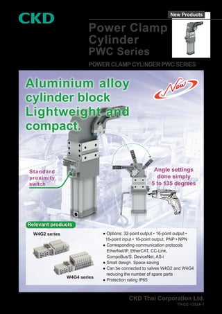
- 1. Power Clamp Cylinder PWC Series POWER CLAMP CYLINDER PWC SERIES CKD Thai Corporation Ltd. TH-CC-1352A-1 Aluminium alloy cylinder block Lightweight and compact. Standard proximity switch Angle settings done simply 5 to 135 degrees ● Options: 32-point output • 16-point output • 16-point input • 16-point output, PNP • NPN ● Corresponding communication protocols EtherNet/IP, EtherCAT, CC-Link, CompoBus/S, DeviceNet, AS-i ● Small design. Space saving ● Can be connected to valves W4G2 and W4G4 reducing the number of spare parts ● Protection rating IP65 Relevant products Relevant products W4G2 series W4G4 series New Products
- 2. 1 Power Clamp Cylinder PWC Series ● Cylinder diameter: φ40/φ50/φ63/φ80 Specifications Description PWC Cylinder diameter mm φ40 φ50 φ63 φ80 Action mechanism Double-acting Working fluid Compressed air Max. working press. MPa 0.8 (8 bar) Min. working press. MPa 0.2 Connecting port size G1/8 G1/4 Open / Close angle Degree 5 to 135 Clamping torque (0.5MPa) N•m 130 185 390 850 Locking torque N•m 380 800 1,500 2,500 Weightkg 1.45 2.7 3.5 8.54 PWC F Arm material G Arm type H Lever color How to order 1 4 R A 50 D1 E G C Sensor B Bore size D Port thread E Arm mount Considerations when choosing an appropriate model: Model no: Clamp cylinder A Operation : Pneumatic / manual lever 1 B Bore size : φ40mm C Sensor : sensor (PNP) D Port thread : G thread E Arm mount : 1 F Arm material : Aluminum G Arm type : Central, Offset 45mm H Lever color : Red PWC-D1-40EG-1A04-R Example of model no. Symbol Description A Operation φ40 φ50 φ63 φ80 P Pneumatic ● ● ● ● G Pneumatic / non manual lever ● ● ● ● D1 Pneumatic / manual lever 1 ● ● ● D2 Pneumatic / manual lever 2 ● B Bore size (mm) 40 φ40 50 φ50 63 φ63 80 φ80 C Sensor E With sensor (PNP) A With sensor (NPN) N No sensor D Port thread G G thread E Arm mount 1 See the drawings on the left (*1) 2 3 4 F Arm material A Aluminum ● ● ● ● S Steel ● ● ● G Arm type Symbol Clamping position Offset 01 Central 15mm (φ40-63) 20mm (φ80) 02 Right 03 Left 04 Central 45mm 05 Right 06 Left H Lever color Blank Black (standard) ● ● ● ● R Red (D1) ● ● ● A Operation *1: D Clamping arm direction 1= 3= 2= 4=
- 3. 2 PWCSeries 2= 1= 3= 4= Clamping arm direction φ40 ● 40mm bore size 16mm axis-offset 15mm ● 40mm bore size 16mm axis-offset 45mm Material Clamping position Weight (kg) Max. opening angle 1 Max. opening angle 2 Max. opening angle 3 Max. opening angle 4 Aluminum alloy Central 0.24 135° 135° N/A 45° Steel Central 0.44 135° 135° N/A 45° Aluminum alloy Right 0.24 135° 135° N/A 45° Steel Right 0.46 135° 135° N/A 45° Aluminum alloy Left 0.24 135° 135° N/A 45° Steel Left 0.46 135° 135° N/A 45° Material Clamping position Weight (kg) Max. opening angle 1 Max. opening angle 2 Max. opening angle 3 Max. opening angle 4 Aluminum alloy Central 0.3 135° 135° N/A N/A Steel Central 0.55 135° 135° N/A N/A Aluminum alloy Right 0.3 135° 135° N/A N/A Steel Right 0.57 135° 135° N/A N/A Aluminum alloy Left 0.3 135° 135° N/A N/A Steel Left 0.57 135° 135° N/A N/A Thread: M6×20 Locking torque: 10N·m Thread: M6×20 Locking torque: 10N·m φ63 ● 63mm bore size 22mm axis-offset 15mm ● 63mm bore size 22mm axis-offset 45mm Material Clamping position Weight (kg) Max. opening angle 1 Max. opening angle 2 Max. opening angle 3 Max. opening angle 4 Aluminum alloy Central 0.52 135° 115° 135° 80° Steel Central 0.9 135° 115° 135° 80° Aluminum alloy Right 0.54 135° 115° 135° 80° Steel Right 0.93 135° 115° 135° 80° Aluminum alloy Left 0.54 135° 115° 135° 80° Steel Left 0.93 135° 115° 135° 80° Material Clamping position Weight (kg) Max. opening angle 1 Max. opening angle 2 Max. opening angle 3 Max. opening angle 4 Aluminum alloy Central 0.57 135° 135° 135° 75° Steel Central 0.98 135° 135° 135° 75° Aluminum alloy Right 0.58 135° 135° 135° 75° Steel Right 1.02 135° 135° 135° 75° Aluminum alloy Left 0.58 135° 135° 135° 75° Steel Left 1.02 135° 135° 135° 75° Thread: M8×25 Locking torque: 25N·m Thread: M8×25 Locking torque: 25N·m φ80 ● 80mm bore size 30mm axis-offset 20mm ● 80mm bore size 30mm axis-offset 45mm Material Clamping position Weight (kg) Max. opening angle 1 Max. opening angle 2 Max. opening angle 3 Max. opening angle 4 Aluminum alloy Central 1.1 135° 110° 135° 75° Aluminum alloy Right 1.15 135° 110° 135° 75° Aluminum alloy Left 1.15 135° 110° 135° 75° Material Clamping position Weight (kg) Max. opening angle 1 Max. opening angle 2 Max. opening angle 3 Max. opening angle 4 Aluminum alloy Central 1.18 135° 110° 135° 75° Aluminum alloy Right 1.2 135° 110° 135° 75° Aluminum alloy Left 1.2 135° 110° 135° 75° Thread: M10×35 Locking torque: 35N·m Thread: M10×35 Locking torque: 35N·m φ50 ● 50mm bore size 19mm axis-offset 15mm ● 50mm bore size 19mm axis-offset 45mm Material Clamping position Weight (kg) Max. opening angle 1 Max. opening angle 2 Max. opening angle 3 Max. opening angle 4 Aluminum alloy Central 0.45 135° 135° 135° 80° Steel Central 0.77 135° 135° 135° 80° Aluminum alloy Right 0.46 135° 135° 135° 80° Steel Right 0.81 135° 135° 135° 80° Aluminum alloy Left 0.46 135° 135° 135° 80° Steel Left 0.81 135° 135° 135° 80° Material Clamping position Weight (kg) Max. opening angle 1 Max. opening angle 2 Max. opening angle 3 Max. opening angle 4 Aluminum alloy Central 0.41 135° 115° 135° 80° Steel Central 0.71 135° 115° 135° 80° Aluminum alloy Right 0.43 135° 115° 135° 80° Steel Right 0.79 135° 115° 135° 80° Aluminum alloy Left 0.43 135° 115° 135° 80° Steel Left 0.79 135° 115° 135° 80° Aluminum alloy Central 0.41 135° 115° 135° 80° Aluminum alloy Right 0.43 135° 115° 135° 80° Aluminum alloy Left 0.43 135° 115° 135° 80° Thread: M6×25 Locking torque: 10 N·m Thread: M6×25 Locking torque: 10 N·m
- 4. 3 PWCSeries ● PWC Dimension ※ Locating pin hole dimension tolerance: ±0.02 Screw hole dimension tolerance: ±0.1 PA±0.05 XB XC XA NE±0.05 KA+0.1 0 NA NB PC±0.05 PD※ PB※ 2×2-MM Depth J 2×2-φ P H7 Depth D NC ND QA QB TB TA KB±0.1 E B RB RE VA※ R RC LB MAX L VC±0.05 VB※ VF±0.1 VD±0.05 VE LA RR RA RD GB GA 2×4-NN Depth S 2×2-φ V H7 Depth I N TC 2-G N φ50 · φ63 AC AB D VERSION AA Code Cylinder diam. (mm) QA QB R RA RB RC RD RE RR S TA TB TC V VA VB VC VD VE VF XA XB XC φ40 40 29.4 33 55 40 50 45 48 34.5 10 29.2 18.5 M12×1 6 35 25 20 47 8H7 7.5 83 28 36 φ50 40 29.4 45 68 45 48 45 47 48 12 29 18.5 M12×1 8 30 32 27 71.5 12N9 11 109 30.5 85.5 φ63 40 29.4 51 78 46 54 45 53 54 12 29 18.5 M12×1 8 30 32 27 71.5 12N9 11 112 33.5 53.5 φ80 40 29.4 74 108 66.6 76 45 69 76 12 29 18.5 M12×1 8 50 50 40 96.5 12N9 15 162 52 69 Code Cylinder diam. (mm) B D E G GA GB I J KA KB L LA LB MM N NA NB NC ND NE NN P PA PB PC PD φ40 62 10 2 G1/8 102.5 106 8 10 40 60 260 161 8 M6 16 4.35 4 4 3 25 M6 6 12 35 38.5 25 φ50 78 12 2 G1/4 118 135 12 12 55 93 314.5 200.5 8 M10 19 10.5 6.5 5.5 4.5 36.5 M8 10 10 50 55 45 φ63 105 12 2 G1/4 130.5 133.5 12 12 55 93 332.5 209.5 9 M8 22 12 7.5 7 7.5 36.5 M8 10 10 50 55 45 φ80 138 12 2 G1/4 187 188 12 12 80 134 474 286 9 M12 30 10 8 8 9 50 M10 12 15 70 65 75 D Version AA AB AC D1 φ40 27 80 187 D1 φ50 27 87.5 221 D1 φ63 27 98.5 220.9 D2 φ80 27 147.5 245
- 5. 4 PWCSeries ● Clamping arm A B±0.1 C±0.1 I J±0.1 N O H E±0.02 F±0.2 G±0.1 M D φK H7 φL D φ50 · φ63 φ40 Code Cylinder diam. (mm) VERSION STEEL MODEL STEEL WEIGHT ALUMINIUM MODEL ALUMINUM WEIGHT A B C D E F G H I J K L M N O φ40 1 CENTRAL PWC-Q1601 570 PWC-B1601 190 117 22 15 16 20 20 90 70 16 6 7 82 34.5 55 2 RIGHT PWC-Q1602 570 PWC-B1602 190 23 3 LEFT PWC-Q1603 570 PWC-B1603 190 4 CENTRAL PWC-Q1604 770 PWC-B1604 260 117 22 45 16 20 20 90 70 16 6 7 82 34.5 55 5 RIGHT PWC-Q1605 770 PWC-B1605 260 23 6 LEFT PWC-Q1606 770 PWC-B1606 260 φ50 1 CENTRAL PWC-Q1901 980 PWC-B1901 340 144 28 15 19 30 30 105 80 20 6 9 95 48 68 2 RIGHT PWC-Q1902 980 PWC-B1902 340 34 3 LEFT PWC-Q1903 980 PWC-B1903 340 4 CENTRAL PWC-Q1904 1070 PWC-B1904 370 144 28 45 19 30 30 105 80 20 6 9 95 48 68 5 RIGHT PWC-Q1905 1070 PWC-B1905 370 34 6 LEFT PWC-Q1906 1070 PWC-B1906 370 φ63 1 CENTRAL PWC-Q2201 1200 PWC-B2201 410 144 28 15 22 30 30 105 80 20 6 9 95 54 78 2 RIGHT PWC-Q2202 1200 PWC-B2202 410 37 3 LEFT PWC-Q2203 1200 PWC-B2203 410 4 CENTRAL PWC-Q2204 1330 PWC-B2204 460 144 28 45 22 30 30 105 80 20 6 9 95 54 78 5 RIGHT PWC-Q2205 1330 PWC-B2205 460 37 6 LEFT PWC-Q2206 1330 PWC-B2206 460 φ80 1 CENTRAL PWC-B3001 2490 179 35 20 30 30 30 140 115 25 6 9 135 76 108 2 RIGHT PWC-B3002 2490 51 3 LEFT PWC-B3003 2490 4 CENTRAL PWC-B3004 860 179 35 45 30 30 30 140 115 25 6 9 135 76 108 5 RIGHT PWC-B3005 860 51 6 LEFT PWC-B3006 860 Dimension
- 6. 5 PWCSeries ● Switch specifications ● Switch Cable specifications Model: PWC-CBL-05 Load voltage DC10 to 30V Internal voltage drop below 2V Load current below 100mA Consumption current below 30mA Short circuit protection protected Protection rating IEC IP68 Ambient temperature –25 to +60°C Power indicator Green LED Releasing indicator Yellow LED Clamping indicator Red LED Output PNP Connector features Product type M12 circular connector with moulded cable Connector type Straight 180° Contacts type Female 4 poles Number of contacts connected 4 Protection class IP69K Rated voltage 250V AC/DC Rated current 4 A Cable features Pneumax cable code EC001-05 Numbers of conductors 4 Conductors section 0,34 mm2 (AWG22) Cable material PUR UL style 21576 C US R Coating colour Black Conductors insulation material TPO Cable length 5000 mm Stripping 35 mm Standard Peeling and tinning 5 mm Standard M5 7.5 13.5 18.5 29.17 90° 18.6 45 20 40 M12×1 Load Load Disconnect Connect Yellow Green Red Brown Black Blue White 1 4 3 2 ON OFF ON + - Power OFF 1 Load Load Disconnect Connect Yellow Green Red Brown Black Blue White 1 4 3 2 ON OFF + - Wiring diagram [PNP] Wiring diagram [NPN] * 5m Cable with connector is available Dimension 5000 45,50 φ14 M12X1 5 +50 -0 35 ±3 ±1 1 BROWN 3 BLUE 4 BLACK 2 WHITE ON OFF Disconnect Connect Yellow Blue Black LOAD LOAD Brown White Green Red 1 4 3 2
- 7. 6 PWCSeries L is the distance from the fulcrum to the center of gravity of the clamping arm. The weight of front-end allowable load should be used within the allowable range. Technical data 0 70 90 110 130 150 170 190 210 L: Center of gravity of clamping arm (mm) 1 2 3 4 5 0.8 s 1.7 s Range of front-end allowable load (kg) Throttle valve not required Throttle valve not required 70 90 110 130 150 170 190 210 230 290 250 270 0 1 2 3 4 5 6 7 8 9 10 11 12 13 14 0.8 s 1.7 s L: Center of gravity of clamping arm (mm) Range of front-end allowable load (kg) Throttle valve not required Throttle valve not required 70 90 110 130 150 170 190 210 230 250 0 1 2 3 4 5 6 7 8 9 10 11 0.8 s 1.7 s L: Center of gravity of clamping arm (mm) Range of front-end allowable load (kg) Throttle valve not required Throttle valve not required 0 50 200 2 4 6 8 10 12 14 16 18 20 22 24 100 150 250 300 350 400 0.9 s 1.8 s L: Center of gravity of clamping arm (mm) Range of front-end allowable load (kg) Throttle valve not required Throttle valve not required Range of front-end allowable load of clamping arm Related description φ40 φ50 φ63 φ80 L Pneumatic components Safety Precautions Be sure to read this section before use. For cylinder common items and cylinder switches, please refer to Pneumatic Cylinder Catalog (CB-029SA). Product-specific caution: Power Clamp Cylinder PWC series Mounting, installation and adjustment Use and maintenance Clamping arm angle adjustment method WARNING WARNING CAUTION ■ Please do not disassemble it, otherwise danger will occur. ■ During equipment maintenance, in order to ensure safety, please take measures separately to prevent the load from falling due to its own weight. ■ Before installation, thoroughly clean the connecting pipe to ensure that there is no foreign matter or chip inside the cylinder. ① Unfold the clamping arm into position. ※ The clamping arm must be opened with compressed air. ② Insert 5mm adjusting screws on both the front and rear of the cylinder with a hexagonal wrench or electric drill. The adjustment can be made according to any opening and closing angle. ※ CAUTION It is not possible to adjust to a position or angle unreachable by the clamping arm.
- 8. THAILAND NETWORK ASIA PACIFIC NETWORK Bangkok Office No. 44, Smooth Life Tower, 19th Floor, Unit 1902, North Sathorn Road, Kwaeng Silom, Khet Bangrak, Bangkok 10500 Thailand Phone: +66-(0)2-267-6300-3 Fax: +66-(0)2-267-6304-5 Mail: supportbkk@ckdthai.com Navanakorn Office 75/15 Moo 11, Paholyothin Road, Tambol Klongneung, Amphur Klongluang, Prathumthani 12120 Thailand Phone: +66-(0)2-908-2056-60 Fax: +66-(0)2-908-2061-62 Mail: nvn@ckdthai.com Lamphun Office 239/1 Moo 4, Tambol Banklang, Amphur Muang Lamphun, Lamphun 51000 Thailand Phone: +66-(0)53-582-116-7 Fax: +66-(0)53-582-079 Mail: lpn@ckdthai.com Korat Office 3078/9 Mittraphap Road, Tambol Naimuang, Amphur Muang Nakhonratchasima, Nakhonratchasima 30000 Thailand Phone: +66-(0)44-213-290-1 Fax: +66-(0)44-213-292 Mail: krt@ckdthai.com Amatanakorn Office 121, 121/1 Moo 2, Tambol Bankao, Amphur Panthong, Chonburi 20160 Thailand Phone: +66-(0)33-002-115-8 Fax: +66-(0)33-002-119-20 Mail: amt@ckdthai.com Eastern Seaboard Office 310/38 Moo 3, Tambol Bowin, Amphur Sriracha, Chonburi 20230 Thailand Phone: +66-(0)38-331-001-4 Fax: +66-(0)38-331-005 Mail: esb@ckdthai.com Rayong Office 267/144 Sukhumvit Road, Tambol Maptaphut, Amphur Muang, Rayong 21150 Thailand Phone: +66-(0)38-608-296 Fax: +66-(0)38-608-297 Mail: rayong@ckdthai.com Prachinburi Office 525/10-11 Moo 8, 3079 Road, Tambol Thatoom, Amphur Srimahaphot, Prachinburi 25140 Thailand Phone: +66-(0)37-218-819-22 Fax: +66-(0)37-218-823 Mail: pcb@ckdthai.com Saraburi Office 36/5 Moo 1, Paholyothin Road, Tambol Daoruang, Amphur Muang, Saraburi 18000 Thailand Phone: +66-(0)36-713-611 Fax: +66-(0)36-713-612 Mail: srb@ckdthai.com Factory 700/58 Moo 1, Bangna - Trad Road KM. 58, Tambol Bankao, Amphur Panthong, Chonburi 20160 Thailand Phone: +66-(0)38-214-646 Fax: +66-(0)38-459-037 Mail: marketing@ckdthai.com M-CKD Precision Sdn. Bhd. Lot No. 6, Jalan Modal 23/2, Seksyen 23, Kawasan MIEL, Fasa 8, 40300 Shah Alam,Selangor Darul Ehsan, Malaysia Phone: +60-(0)3-5541-1468 Fax: +60-(0)3-5541-1533 Mail: sales@mckd.com.my CKD Singapore Pte. Ltd. 33 Tannery Lane, #04-01 Hoesteel Industrial Building, Singapore 347789, Singapore Phone: +65-6744-2623 Fax: +65-6744-2486 Mail: sales@ckdsin.com.sg Asia Pacific Branch Office 33 Tannery Lane, #04-01 Hoesteel Industrial Building, Singapore 347789, Singapore Phone: +65-6744-7260 Fax: +65-6842-1022 PT CKD TRADING INDONESIA Wisma Keiai, 17th Floor, Jl. Jendral Sudirman Kav. 3, Jakarta 10220, Indonesia Phone: +62-(0)21-572-3220 Fax:+62-(0)21-573-4112 Mail: sales@ckdti.co.id CKD Vietnam Engineering Co., Ltd. 18th Floor, CMC Tower, Duy Tan Street, Cau Giay District, Hanoi, Vietnam Phone: +84-4-37957631 Fax: +84-4-37957637 Mail: sales@ckdve.com.vn CKD India Private Limited Unit No. 607, 6th Floor, Welldone Tech Park, Sector 48, Sohna Road, Gurgaon-122018, Haryana, India Phone: +91-(0)124-418-8212 Fax: +91-(0)124-418-8216 Mail: imai@ckdin.co.in CALL CENTER: 02-267-6300 | MARKETING@CKDTHAI.COM | WWW.CKDTHAI.COM 2018.4 CALL CENTER: 02-267-6300 | MARKETING@CKDTHAI.COM | WWW.CKDTHAI.COM ●Specifications are subject to change without notice. © CKD Corporation 2018 All copy rights reserved.