
Recommandé
Contenu connexe
Tendances
Tendances (19)
Similaire à Peter Cox - Dryroom Basement Waterproofing
Similaire à Peter Cox - Dryroom Basement Waterproofing (20)
Plus de Kevin Ball
Dernier
Dernier (20)
Peter Cox - Dryroom Basement Waterproofing
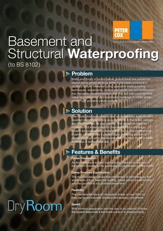
- 1. Basement and Structural Waterproofing Walls and floors in rooms below ground level are subject to lateral damp penetration by either hydrostatic pressure or capillary action. However using specialist waterproofing techniques, basements, cellars and vaults can be transformed into habitable accommodation and this can add considerable value to commercial and residential buildings in urban areas where high property values prevail. The cavity drainage system uses a high density extruded and studded membrane acting as a dry lining to the walls, ceilings and floors with an air gap behind. This allows for the free movement of water which is channelled into a drainage system for evacuation outside the building. The internal wall finishes can be either a plasterboard dry lining system or plastering direct on to the membrane. The floor finish is either screeded or timber boarded. Problem Solution Faster Preparation As the membrane is fixed mechanically, there is no reliance on the system bonding to the substrate, so preparation is less critical. Damp Pressure Equalisation The studded design allows free movement of dampness so the whole wall or floor takes the loading. Weak points are eliminated and the problem is not diverted elsewhere. Flexibility The membranes have an elongation break of over 50% so they can accommodate vibration and building movement. Speed With minimal preparation and the use of dry internal finishes, the system becomes a fast track solution to waterproofing. Features & Benefits (to BS 8102) S2362-DryRoom Basement Waterproofing Datasheet:Layout 1 13/01/2014 10:21 Page 1
- 2. The membrane used is high performance polyethylene or polypropylene which is resistant to chemicals and temperature extremes. The sheet is formed with a series of studs which are designed to create a continuous air gap behind the membrane and to provide a channel for water removal to a drainage system under the floor. Regardless of whether free water is present, to comply with BS8102, the waterproofing system must be designed to accommodate water removal behind the lining either through natural drainage or a sump and pump installation. The membrane is fixed with waterproofing plugs and the floor / wall junction is sealed using a proprietary jointing compound. Installations that comply with BS8102 carry a 10 year waterproofing guarantee. Cavity Drainage Membrane Specification Freephone 0800 789 500 www.petercox.com Aniseed Park, Broadway Business Park Chadderton, Manchester, OL9 9XA Email: enquiries@petercox.com Peter Cox Ltd Our Range of Plaster Finishes Membrane Waterproofing System to meet BS8102 Waterproof fixing plugs provide a secondary fixing point for internal dry lining with plasterboard (and insulation if required) fixed to a timber stud frame. Alternatively an independent metal channel system can be installed. If preferred and where internal space is at a premium, an alternative membrane can be installed (complete with a welded mesh) for a direct plaster finish. Wall lining The floor membrane has deeper 20mm studs for extra drainage capacity and can be finished either with a concrete screed or T & G chipboard flooring, laid or fixed respectively direct on to the membrane. Floor Lining The concept of the cavity drainage system is to collect and manage the dispersal of any free water. Where no existing drainage is available, this is usually achieved via drainage channels around the wall perimeter and across the floor leading to a sump chamber fitted with an evacuation pump(s). Drainage A ventilated dry lining system can be installed without full drainage provision in order to give protection from damp or salt contamination. However it will not resist water pressure and so cannot be guaranteed waterproof. Dry Lining System (without drainage) Plasterboard Dry Lining Dab Fixed Plasterboard Direct Plaster Finish S2362-DryRoom Basement Waterproofing Datasheet:Layout 1 13/01/2014 10:21 Page 2
- 3. Water collection and discharge can be done passively via existing drainage points but in the majority of projects perimeter drainage is installed along with a submersible pump in a sump chamber. This then becomes the key element in the system of waterproofing below ground. To ensure adequate protection is provided, Peter Cox have a series of 'back-up' options to reduce the risk of failure. Drainage Freephone 0800 789 500 www.petercox.com Aniseed Park, Broadway Business Park Chadderton, Manchester, OL9 9XA Email: enquiries@petercox.com Peter Cox Ltd Power Failure Protection Pump The principal drainage channel is installed around the perimeter of the room bedded in to a rebate at the wall floor junction. This is a rigid plastic pipe with holes to allow water ingress and access ports to allow maintenance and inspection access. Drainage Channels This is designed to run the pumps for one hour if power failure occurs and will pump nearly 7000 litres in back-up mode. The pump systems are designed to manage the discharge of water automatically. However in the event of power failure coinciding with high levels of water ingress, three options are available. Battery Back-Up Pack This gives an audible warning if a high water level situation occurs. It is fitted with a trickle charge so will still operate when mains power fails. High Level Alarm This system is designed for situations where early warning of pump failure is a high priority. It can be programmed to alert by email, SMS text message or phone (mobile or landline). Text messages can be sent to up to 5 mobile phones. Telemetric Alarm System In most circumstances Peter Cox recommend the inclusion of a dual drainage system with two submersible float activated pumps fitted into a preformed sump chamber and complete with built in non-return valves. Water is collected from the floor channels through the clear opening at the top of the unit. The two pumps are usually set at different levels with one acting as standby. Sumps are fitted with a sealed access cover which facilitates maintenance and servicing checks. As part of the standard commissioning routine, systems are flood tested to confirm operational integrity before the access cover is sealed. Sumps & Pumps S2362-DryRoom Basement Waterproofing Datasheet:Layout 1 13/01/2014 10:21 Page 3
- 4. Installation Freephone 0800 789 500 www.petercox.com Aniseed Park, Broadway Business Park Chadderton, Manchester, OL9 9XA Email: enquiries@petercox.com Peter Cox Ltd Sealed system with drainage protection Cavity Drainage Membrane Section showing fixing detail Studded Membrane Plug with rope seal Vertical timber battens Plasterboard Service Pipe Sump & Pump Detail Wall/floor details on sealed system. Dry Lining System Rope applied around Sump cover circumference sealing pipe & membrane Service pipe Service pipe Rope Studded Membrane Studded Membrane Sump cover Exit hose from the pump should be sited in the most convenient position to take excess water away from the property Submersible pump Concrete or pre-formed polyethylene chamber Rope seal Rope sealing floor application to wall. Floor membrane is returned up the wall Mastic seal Mastic seal Floor Membrane Standard Membrane Membrane with mesh on the walls Studded Membrane fixed to wall Wall lining Air flow Air flow Cavity drainage membrane to wall Plasterboard lining on battens Membrane fixed with sealed plug Corner strip overseal at wall/floor joint Drainage channel Screeded or timber floor Drainage membrane to floor Water drains into back of channel S2362-DryRoom Basement Waterproofing Datasheet:Layout 1 13/01/2014 10:21 Page 4