Band edge engineering of composite photoanodes for dye sensitized solar cells
NISTpresentation
1. Testing with the Open-Cell Method
Layered TiO2 and ITO Structures in Dye-Sensitized Solar Cells
Kirsten M. Runyan, Nicholas O. Chisholm, Hans H. Funke, and John L. Falconer
Department of Chemical and Biological Engineering, University of Colorado at Boulder
Research Objective
• Thicker layers of TiO2 mean greater dye loading which would mean greater light
harvesting and higher current if it weren’t for electron recombination
• Electrons have an electron diffusion length (modeled by random walk) that is
characterized by the point where recombination with the oxidized dye molecules
or electrolyte becomes likely
• The electron diffusion length is observed to be approximately 15-20µm (see Figure
1)
Adding a Conductive Layer to Effectively Increase the
Electron Diffusion Length
Conclusions and Future Work
Preliminary Work on ITO Coated Glass
1. The work function of porous ITO on glass is lower than the work function of dense
ITO on glass due to the voltage drop
2. The electron diffusion length is about 10µm
3. Cell type 4 is about 2 times the current of type 2
4. Cell type 5 having a lower current than type 4 suggests there may be some
electron recombination sites on nanoparticle ITO
Recent Work with FTO Coated Glass
1. The work function of FTO on glass is greater than the work function of porous ITO
creating an electron barrier, thereby, inhibiting electron flow
2. Film cracking may reduce electron mobility resulting in lower photocurrent
Future Work
1. Further development of paste recipe that results in crack-free, mechanically
stable films
2. Other deposition methods for ITO and TiO2 nanoparticles (sputtering, spin
coating)
3. Replication of preliminary work on ITO coated glass using in-house prepared ITO
nanoparticles
4. Investigation of other ITO and TiO2 layered structures
5. Investigate film cracking on photocurrent and efficiency
Background
How Do DSSCs Work?
• Dye Sensitized Solar Cells (DSSCs) are electrochemical multi-junction photovoltaics
with an anode and a cathode, first created by Gratzel
• The anode is comprised of a mesoporous semiconductor layer of TiO2
nanoparticles dyed with a molecular sensitizer (a ruthenium dye) all layered on a
transparent conducting oxide (TCO) film
References
1. Man Gu Kang, Kwang Sun Ryu, Soon Ho Chang, Nam Gyu Park, Jin Sup Hong†, and
Kang-Jin Kim, Dependence of TiO2 Film Thickness on Photocurrent-Voltage
Characteristics of Dye-Sensitized Solar Cells, 2003.
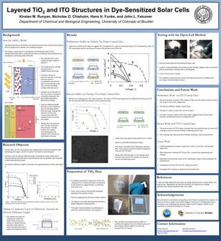
Results
Preliminary Studies on Indium Tin Oxide Coated Glass
• Preliminary studies by Dr. Miao Yu suggest that the addition of a porous conductive layer of ITO betweenTiO2 layers on
ITO coated glass (porous and dense) increases the photocurrent of the cell
Recent Studies on Fluorine Tin Oxide Coated Glass
• Results from adding porous ITO layers between TiO2 layers on FTO coated glass (dense) indicate the photocurrent of
the cell decreases with the addition of the conductive layer
Acknowledgements
Many thanks for contributions and guidance from Miao Yu along with the support and
direction of Rich D. Noble and Prashant Nagpal. Thank you to the National Science
Foundation and Undergraduate Research Opportunities Program (UROP) at the
University of Colorado at Boulder for funding.
Preparation of TiO2 films
• The cathode of the cell is
conductive glass coated in
platinum
• The anode and the cathode
are joined by an
iodide/triiode electrolyte
• A photon creates an
electron-hole pair in the dye
molecule which is
immediately split with the
electron percolating to the
TiO2 and the electrolyte
acting as the hole carrier
• Injection of the electron to
the TiO2 results in oxidation
of the dye molecules, the
electrolyte replenishes
electrons in the dye
• Electrons diffuse through
the TiO2 to the conductive
layer on the glass where
they then pass through the
external circuit to the
counter electrode then
replenish electrons in the
electrolyte
• Ideally, after the electrons
leave the dye molecules;
they will pass through
theTiO2 film without
recombining with any
oxidized dye molecules or
electrolyte molecules
Contact Information
Kirsten Runyan Nicholas Chisholm
kirsten.runyan@colorado.edu nicholas.chisholm@colorado.edu
720-317-5229
Figure 1 : Plots from literature demonstrating the decline in efficiency and current as the
thickness of the TiO2 film increases. 1
• The addition of a layer of
transparent conductive
oxide (TCO) in this case
Indium Tin Oxide (ITO) will
provide a closer path by
which the electrons may to
travel to the external circuit
• TiO2 wet films are heated slowly to 300 0C to
volatilize off organics from the colloidal paste and
then slowly heated to 500 0C to sinter the
nanoparticles to anatase
• A colloidal nanoparticle suspension of P25 TiO2
nanoparticles is created with water and ethanol
as the solvent, an organic binder, a surfactant,
and acetic acid
• Acetic acid is used to increase dye loading by
exposing more particle surface
• Films are deposited by the doctor blade method
• The figures to the right illustrates the full doctor
blade method for producing films
• Films were characterized by a profilometer to
check for uniform thickness and roughness
• Cells are tested without fully sealing the solar cells
• A spacer is placed between the anode and the cathode, alligator clips are attached
and the electrolyte is injected with a micropipette
• A 5mm x 5mm area is masked
• This method is easier than the closed cell method and prevents bubbles from
occurring in the electrolyte solution
• Fewer shunt and series losses observed in IV curves
• Seems to contradict preliminary results
• This result is possibly due to observed cracking in
films that prevents electron mobility through the
TiO2 and the FTO layer
• Dense FTO could also have a much greater work
function than porous ITO, acting as an electron
barrier and lowering current
100 µm