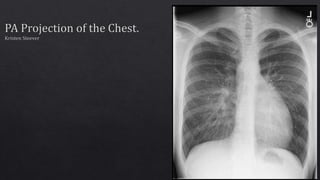
SlideShare a Scribd company logo
1 of 18
• The image is HIPAA compliant .
• There is no evidence of patient information
displayed on this image. Therefore, patient
information has been kept confidential and
has not been violated.
• The correct anatomical marker is on the image.
• There are no markers superimposed on pertinent
anatomy.
• An additional marker could be placed on this
image to help indicate that the image was taken in
PA position. An erect marker is not needed since
the three beads in the circle under the
technologist’s initials indicate the patient was
erect.
• Based on marker placement, this image was
displayed correctly. The left marker is on the
correct side of the patient and it appears on the
viewer’s right side. However, the marker should
have been flipped so that the “L” would not appear
backwards on the resulting image. The lettering
should have been facing towards the image
receptor and not towards the technologist.
• There must be at least three sides
of beam restriction on the image.
• There appears to be three sides of
beam restriction on this image
because of the white appearance
surrounding the edges.
• The gonads of the patient must be
shielded if they are within 5 cm of
the primary beam. There is
evidence of beam restriction on the
side closest to the gonads.
Beam restriction on side
closest to gonads.
Routine Projections:
• PA projection with perpendicular beam
• Lateral Projection with perpendicular beam
All anatomical parts are correctly visualized on this
image. The image includes the whole lung field from
the apices to the costophrenic angles.
• The following are not present in this image:
• Preventable artifacts
• Body parts superimposing that should
not be superimposed.
• Hospital paraphernalia.
• Patient belonging artifacts.
• Indwelling foreign bodies.
• CR/DR artifacts.
• Visible excess fog that is degrading the
image quality.
• There is no evidence of gross voluntary
movement in this image. Pertinent
anatomy is well defined and does not
appear to be blurred. Lung markings are
seen clearly. However, there may have
been slight movement of the clavicles
due to blurry appearance, but this is not
the anatomy of interest.
• There is no evidence of gross quantum
mottle in this image because a
grainy/mottled appearance is not
present.
• There is no evidence of double exposure
in this image. There is only one marker
and a ghosted image is not present.
• There is no evidence of grid lines/grid
cut-off or grid artifacts in this image. An
oscillating high frequency grid and
proper SID were most likely utilized.
Slight blur indicating
movement of clavicles.
• Size distortion does not appear greater than
expected.
• The centering for an erect PA Chest projection is
at T7 (blue star).
• Since the CR in this image is centered inferiorly
to T7, just about on T8, there may be slight
shape distortion. However, the centering is
within 1 cm of proper centering in my opinion,
so shape distortion will not be drastic.
1
2
3
4
5
6
7
8
• The part is properly aligned to the long axis of the
image media (red line). The viewer does not have to
tilt their head to see the image in its proper display.
• The part is not accurately centered to the image media.
The CR should be centered at the T7 (blue star). In this
image, the CR is centered to T8 (intersection of yellow
lines).
• I believe the CR is centered within 1 cm of the part.
Therefore, shape distortion is minimal and will not
degrade image quality.
• Assuming that the black edges of the image represent
the image media, the CR appears to be properly
centered to the image media. (intersection of green
lines).
1
2
3
4
5
6
7
8
• Since three sides of beam restriction can be seen,
this image follows an appropriate exposure field
template.
1
2
3
Position of Patient for an erect
PA Chest:
• If possible, always examine
patients in the upright position,
either standing or seated, so
that the diaphragm is at its
lowest position, and air or fluid
levels are seen. Engorgement of
the pulmonary vessels is also
avoided.
Source: Merrill’s Atlas 13th edition
Volume 1 Pg. 497-498
Position of Part for an erect PA
Chest:
• Place the patient, with arms hanging at
sides, before a vertical grid device.
• Adjust the height of the IR so that its upper
border is about 1.5 to 2 inches (3.8 to 5
cm) above the relaxed shoulders.
• Center the midsagittal plane of the
patient’s body to the midline of the IR.
• Have the patient stand straight, with the
weight of the body equally distributed on
the feet,
• Extend the patient’s chin upward or over
the top of the grid device, and adjust the
head so that the midsagittal plane is
vertical.
• Ask the patient to flex the elbows and to
rest the backs of the hands low on the hips,
below the level of the costophrenic angles.
Depress the shoulders and adjust to lie in
the same transverse plane. These
movements will position the clavicles
below the apices of the lungs.
• Rotate the shoulders forwards so that both
touch the vertical grid device. This
movement will rotate the scapulae
outward and laterally to reduce
superimposition of the scapulae with the
lungs.
• If an immobilization band is used, be
careful not to rotate the body when
applying the band.
Collimation:
• 14 x 17 inches lengthwise.
• Crosswise for hypersthenic patients.
CR:
• Perpendicular to the center of the
IR. The central ray should enetr at
the level of T7 (inferior angle of the
scapula)
SID:
• 72 inches.
• The least amount of rotation results in
considerable distortion of the heart shadow.
• If a female patient’s breasts are large enough
to be superimposed of the lower part of the
lung fields, especially the costophrenic
angles, ask the patient to pull the breasts
upward and laterally. This is especially
important when ruling out the presence of
fluid. Have the patient hold the breasts in
place by leaning against the IR holder.
• Shield gonads. Place a lead strip between
the patient and the x-ray tube.
***SIDE NOTE***
• It is best to place a lead shield in front of the
patient for this projection. This is because
more scatter radiation is being received by the
patient’s gonads anteriorly. The best lead
apron to use would be one that acts as a skirt
that covers the anterior and posterior of the
patient.
• Respiration: Full inspiration. The exposure is
made after the second full inspiration to
ensure maximum expansion of the lungs. The
lungs expand transversely, anteroposteriorly,
and vertically, with vertical being the greatest
dimension.
Images from Merrill’s Atlas 13th Edition
Volume 1 Page 496 and 498
Beam restriction
for gonads.
• For certain conditions, such as
pneumothorax and the presence of a
foreign body, radiographs are sometimes
made at the end of full inspiration and
expiration. Pneumothorax is shown more
clearly on expiration because collapse of
the lung is accentuated.
• The above picture demonstrates
Pneumothorax of the right lung with
radiograph taken during expiration.
• Orient the CR
crosswise for
hypersthenic
patients.
(Merrill’s Atlas Volume 1 page 394)
Apices
Costophrenic
Angles
The sternal ends of the clavicles
are not equidistant from the
vertebral column. There
appears to be slight rotation to
the patient’s right side, since the
right clavicle is farther away
from the vertebral column.
Trachea in
midline
The right side is wider than the left side.
McQuillen Martensen Image Evaluation
(McQuillen Martensen 4th Edition Pg. 88)
1
2
3
4
5
6
7
8
9
10
4th thoracic
vertebra
superimposing
manubrium
About 1 inch of
apical lung field
above clavicle.
Centered at T8
instead of T7
Apices
Costophrenic
Angles
Right border of posterior
ribs are farther from
vertebral column than
left, due to slight rotation
to the right side.
Right clavicle is
slightly higher
than left.
Right sternal clavicular end is farther than left.
• The most radiolucent structure in this image is the air
within the lung field and the trachea.
• The most radiopaque structure in this image is the
bony cortex of the spine, ribs, and clavicles.
• The image contrast is adequate in this image since
variations of gray differentiate structures from one
another. The image has a long scale contrast which is
needed for proper visualization of structures of the
thoracic viscera.
• There is no EI value to go with this image, but since
quantum mottle is not seen and structures in the lungs
such as the vessels and heart can be seen, the image's
brightness is adequate to visualize all anatomical
structures necessary.
• This image is of diagnostic quality and should not
be repeated. It seems to have an appropriate EI
value and all pertinent anatomy is visualized on
this image.
• The marker should be placed so that it should
face in its proper position for the viewer.
• The CR should be centered at T7, not T8.
• Clavicles need to be on the same horizontal
plane. The right clavicle is higher than the left
clavicle.
• The sternal ends of the clavicles must be at an
equal distance from the vertebral column on
both sides. The distance between the vertebral
column and the lateral border of the lungs
must also be equidistant on each side.
• Since the right sternal clavicular end is farther
from the vertebral column than the left, and
the right clavicle is higher on a horizontal
plane than the left, the patient was over
rotated to the right side and should be rotated
slightly more to the left side. This will put both
sternal clavicular ends on the vertebral column
and lung fields will be symmetrical.
Kristen Steever PA Chest

More Related Content

What's hot

What's hot (20)

Technique 1 Upper limbs 1
Technique 1 Upper limbs 1Technique 1 Upper limbs 1
Technique 1 Upper limbs 1
 
Lumbo sacral,coccyx sacrum anatomy and positioning
Lumbo sacral,coccyx sacrum anatomy and positioningLumbo sacral,coccyx sacrum anatomy and positioning
Lumbo sacral,coccyx sacrum anatomy and positioning
 
Mammography positioning technique for MLO View
Mammography positioning technique for MLO View Mammography positioning technique for MLO View
Mammography positioning technique for MLO View
 
Sella Turcica (RAD32)
Sella Turcica (RAD32)Sella Turcica (RAD32)
Sella Turcica (RAD32)
 
Technique 1 Upper limbs 3
Technique 1 Upper limbs 3Technique 1 Upper limbs 3
Technique 1 Upper limbs 3
 
Technique 1 Lower limbs 2
Technique 1 Lower limbs 2Technique 1 Lower limbs 2
Technique 1 Lower limbs 2
 
PA Hand Final
PA Hand FinalPA Hand Final
PA Hand Final
 
Technique 1 Lower limbs 3
Technique 1 Lower limbs 3Technique 1 Lower limbs 3
Technique 1 Lower limbs 3
 
Essential radioloic anatomy_mrcs
Essential radioloic anatomy_mrcsEssential radioloic anatomy_mrcs
Essential radioloic anatomy_mrcs
 
Chest x-ray.zp162335
Chest x-ray.zp162335Chest x-ray.zp162335
Chest x-ray.zp162335
 
Radiographic views of sacrum and coccyx
Radiographic views of sacrum and coccyxRadiographic views of sacrum and coccyx
Radiographic views of sacrum and coccyx
 
A scan
A  scanA  scan
A scan
 
X-RAY PELVIS PROJECTIONS
X-RAY PELVIS PROJECTIONSX-RAY PELVIS PROJECTIONS
X-RAY PELVIS PROJECTIONS
 
Mammography Positioning Technique for Additional Views
Mammography Positioning Technique for Additional Views Mammography Positioning Technique for Additional Views
Mammography Positioning Technique for Additional Views
 
Ncct and cect brain and orbit
Ncct and cect brain and orbitNcct and cect brain and orbit
Ncct and cect brain and orbit
 
Mammography positioning technique for Cranio Caudal (CC)
Mammography positioning technique for Cranio Caudal (CC) Mammography positioning technique for Cranio Caudal (CC)
Mammography positioning technique for Cranio Caudal (CC)
 
SKULL: Radiologic Positioning (Non-contrast)
SKULL: Radiologic Positioning (Non-contrast)SKULL: Radiologic Positioning (Non-contrast)
SKULL: Radiologic Positioning (Non-contrast)
 
Pelvic radiographs
Pelvic radiographsPelvic radiographs
Pelvic radiographs
 
Approach to Chest X-Ray and Interpretation
Approach to Chest X-Ray and InterpretationApproach to Chest X-Ray and Interpretation
Approach to Chest X-Ray and Interpretation
 
Portable kub
Portable kubPortable kub
Portable kub
 

Similar to Kristen Steever PA Chest

Basic Chest X ray Views - AP, PA & Lateral etc . pptx
Basic Chest X ray Views - AP, PA & Lateral etc . pptxBasic Chest X ray Views - AP, PA & Lateral etc . pptx
Basic Chest X ray Views - AP, PA & Lateral etc . pptx
Dr Abna J
 

Similar to Kristen Steever PA Chest (20)

Learn Chest X-Ray With Its Normal Positioning & Radio-Anatomy
Learn Chest X-Ray With Its Normal Positioning & Radio-AnatomyLearn Chest X-Ray With Its Normal Positioning & Radio-Anatomy
Learn Chest X-Ray With Its Normal Positioning & Radio-Anatomy
 
Image Evaluation: Stretcher Chest
Image Evaluation: Stretcher ChestImage Evaluation: Stretcher Chest
Image Evaluation: Stretcher Chest
 
Final Image Evaluation: Left Lateral Lumbar Spine
Final Image Evaluation: Left Lateral Lumbar SpineFinal Image Evaluation: Left Lateral Lumbar Spine
Final Image Evaluation: Left Lateral Lumbar Spine
 
Basic Chest X ray Views - AP, PA & Lateral etc . pptx
Basic Chest X ray Views - AP, PA & Lateral etc . pptxBasic Chest X ray Views - AP, PA & Lateral etc . pptx
Basic Chest X ray Views - AP, PA & Lateral etc . pptx
 
Image Evaluation: AP Axial C-Spine
Image Evaluation: AP Axial C-SpineImage Evaluation: AP Axial C-Spine
Image Evaluation: AP Axial C-Spine
 
Normal chest x ray and collapse
Normal chest x ray and collapseNormal chest x ray and collapse
Normal chest x ray and collapse
 
Wrist presentation
Wrist presentationWrist presentation
Wrist presentation
 
R NKUNA X_RAY INTERPRETATION 2020.pptx Physiotherapy
R NKUNA X_RAY INTERPRETATION 2020.pptx PhysiotherapyR NKUNA X_RAY INTERPRETATION 2020.pptx Physiotherapy
R NKUNA X_RAY INTERPRETATION 2020.pptx Physiotherapy
 
chest.pptx
chest.pptxchest.pptx
chest.pptx
 
Foto polos cervical - Irfani Ryan.pptx
Foto polos cervical - Irfani Ryan.pptxFoto polos cervical - Irfani Ryan.pptx
Foto polos cervical - Irfani Ryan.pptx
 
Chest X-ray: Basics
Chest X-ray: BasicsChest X-ray: Basics
Chest X-ray: Basics
 
Radiography clinical updates - session one
Radiography clinical updates - session one Radiography clinical updates - session one
Radiography clinical updates - session one
 
Oblique knee final evaluation
Oblique knee final evaluationOblique knee final evaluation
Oblique knee final evaluation
 
Final Image Evaluation
Final Image EvaluationFinal Image Evaluation
Final Image Evaluation
 
Presentation2.pptx technique chest 2
Presentation2.pptx technique chest 2Presentation2.pptx technique chest 2
Presentation2.pptx technique chest 2
 
Chest x ray quality - how to interpret chest x-ray (1)
Chest x ray quality - how to interpret chest x-ray (1)Chest x ray quality - how to interpret chest x-ray (1)
Chest x ray quality - how to interpret chest x-ray (1)
 
Chest radiography ppt
Chest radiography pptChest radiography ppt
Chest radiography ppt
 
Chest radiology
Chest radiologyChest radiology
Chest radiology
 
X ray c-spine
X ray c-spineX ray c-spine
X ray c-spine
 
D torres lower_leg_oralppt3
D torres lower_leg_oralppt3D torres lower_leg_oralppt3
D torres lower_leg_oralppt3
 

Recently uploaded

The basics of sentences session 3pptx.pptx
The basics of sentences session 3pptx.pptxThe basics of sentences session 3pptx.pptx
The basics of sentences session 3pptx.pptx
heathfieldcps1
 
Spellings Wk 3 English CAPS CARES Please Practise
Spellings Wk 3 English CAPS CARES Please PractiseSpellings Wk 3 English CAPS CARES Please Practise
Spellings Wk 3 English CAPS CARES Please Practise
AnaAcapella
 

Recently uploaded (20)

Application orientated numerical on hev.ppt
Application orientated numerical on hev.pptApplication orientated numerical on hev.ppt
Application orientated numerical on hev.ppt
 
The basics of sentences session 3pptx.pptx
The basics of sentences session 3pptx.pptxThe basics of sentences session 3pptx.pptx
The basics of sentences session 3pptx.pptx
 
Spatium Project Simulation student brief
Spatium Project Simulation student briefSpatium Project Simulation student brief
Spatium Project Simulation student brief
 
REMIFENTANIL: An Ultra short acting opioid.pptx
REMIFENTANIL: An Ultra short acting opioid.pptxREMIFENTANIL: An Ultra short acting opioid.pptx
REMIFENTANIL: An Ultra short acting opioid.pptx
 
ICT Role in 21st Century Education & its Challenges.pptx
ICT Role in 21st Century Education & its Challenges.pptxICT Role in 21st Century Education & its Challenges.pptx
ICT Role in 21st Century Education & its Challenges.pptx
 
ICT role in 21st century education and it's challenges.
ICT role in 21st century education and it's challenges.ICT role in 21st century education and it's challenges.
ICT role in 21st century education and it's challenges.
 
Unit 3 Emotional Intelligence and Spiritual Intelligence.pdf
Unit 3 Emotional Intelligence and Spiritual Intelligence.pdfUnit 3 Emotional Intelligence and Spiritual Intelligence.pdf
Unit 3 Emotional Intelligence and Spiritual Intelligence.pdf
 
HMCS Vancouver Pre-Deployment Brief - May 2024 (Web Version).pptx
HMCS Vancouver Pre-Deployment Brief - May 2024 (Web Version).pptxHMCS Vancouver Pre-Deployment Brief - May 2024 (Web Version).pptx
HMCS Vancouver Pre-Deployment Brief - May 2024 (Web Version).pptx
 
TỔNG ÔN TẬP THI VÀO LỚP 10 MÔN TIẾNG ANH NĂM HỌC 2023 - 2024 CÓ ĐÁP ÁN (NGỮ Â...
TỔNG ÔN TẬP THI VÀO LỚP 10 MÔN TIẾNG ANH NĂM HỌC 2023 - 2024 CÓ ĐÁP ÁN (NGỮ Â...TỔNG ÔN TẬP THI VÀO LỚP 10 MÔN TIẾNG ANH NĂM HỌC 2023 - 2024 CÓ ĐÁP ÁN (NGỮ Â...
TỔNG ÔN TẬP THI VÀO LỚP 10 MÔN TIẾNG ANH NĂM HỌC 2023 - 2024 CÓ ĐÁP ÁN (NGỮ Â...
 
Basic Civil Engineering first year Notes- Chapter 4 Building.pptx
Basic Civil Engineering first year Notes- Chapter 4 Building.pptxBasic Civil Engineering first year Notes- Chapter 4 Building.pptx
Basic Civil Engineering first year Notes- Chapter 4 Building.pptx
 
How to setup Pycharm environment for Odoo 17.pptx
How to setup Pycharm environment for Odoo 17.pptxHow to setup Pycharm environment for Odoo 17.pptx
How to setup Pycharm environment for Odoo 17.pptx
 
80 ĐỀ THI THỬ TUYỂN SINH TIẾNG ANH VÀO 10 SỞ GD – ĐT THÀNH PHỐ HỒ CHÍ MINH NĂ...
80 ĐỀ THI THỬ TUYỂN SINH TIẾNG ANH VÀO 10 SỞ GD – ĐT THÀNH PHỐ HỒ CHÍ MINH NĂ...80 ĐỀ THI THỬ TUYỂN SINH TIẾNG ANH VÀO 10 SỞ GD – ĐT THÀNH PHỐ HỒ CHÍ MINH NĂ...
80 ĐỀ THI THỬ TUYỂN SINH TIẾNG ANH VÀO 10 SỞ GD – ĐT THÀNH PHỐ HỒ CHÍ MINH NĂ...
 
Fostering Friendships - Enhancing Social Bonds in the Classroom
Fostering Friendships - Enhancing Social Bonds  in the ClassroomFostering Friendships - Enhancing Social Bonds  in the Classroom
Fostering Friendships - Enhancing Social Bonds in the Classroom
 
Graduate Outcomes Presentation Slides - English
Graduate Outcomes Presentation Slides - EnglishGraduate Outcomes Presentation Slides - English
Graduate Outcomes Presentation Slides - English
 
How to Create and Manage Wizard in Odoo 17
How to Create and Manage Wizard in Odoo 17How to Create and Manage Wizard in Odoo 17
How to Create and Manage Wizard in Odoo 17
 
FSB Advising Checklist - Orientation 2024
FSB Advising Checklist - Orientation 2024FSB Advising Checklist - Orientation 2024
FSB Advising Checklist - Orientation 2024
 
Spellings Wk 3 English CAPS CARES Please Practise
Spellings Wk 3 English CAPS CARES Please PractiseSpellings Wk 3 English CAPS CARES Please Practise
Spellings Wk 3 English CAPS CARES Please Practise
 
SKILL OF INTRODUCING THE LESSON MICRO SKILLS.pptx
SKILL OF INTRODUCING THE LESSON MICRO SKILLS.pptxSKILL OF INTRODUCING THE LESSON MICRO SKILLS.pptx
SKILL OF INTRODUCING THE LESSON MICRO SKILLS.pptx
 
General Principles of Intellectual Property: Concepts of Intellectual Proper...
General Principles of Intellectual Property: Concepts of Intellectual  Proper...General Principles of Intellectual Property: Concepts of Intellectual  Proper...
General Principles of Intellectual Property: Concepts of Intellectual Proper...
 
How to Give a Domain for a Field in Odoo 17
How to Give a Domain for a Field in Odoo 17How to Give a Domain for a Field in Odoo 17
How to Give a Domain for a Field in Odoo 17
 

Kristen Steever PA Chest

  • 1.
  • 2. • The image is HIPAA compliant . • There is no evidence of patient information displayed on this image. Therefore, patient information has been kept confidential and has not been violated.
  • 3. • The correct anatomical marker is on the image. • There are no markers superimposed on pertinent anatomy. • An additional marker could be placed on this image to help indicate that the image was taken in PA position. An erect marker is not needed since the three beads in the circle under the technologist’s initials indicate the patient was erect. • Based on marker placement, this image was displayed correctly. The left marker is on the correct side of the patient and it appears on the viewer’s right side. However, the marker should have been flipped so that the “L” would not appear backwards on the resulting image. The lettering should have been facing towards the image receptor and not towards the technologist.
  • 4. • There must be at least three sides of beam restriction on the image. • There appears to be three sides of beam restriction on this image because of the white appearance surrounding the edges. • The gonads of the patient must be shielded if they are within 5 cm of the primary beam. There is evidence of beam restriction on the side closest to the gonads. Beam restriction on side closest to gonads.
  • 5. Routine Projections: • PA projection with perpendicular beam • Lateral Projection with perpendicular beam All anatomical parts are correctly visualized on this image. The image includes the whole lung field from the apices to the costophrenic angles.
  • 6. • The following are not present in this image: • Preventable artifacts • Body parts superimposing that should not be superimposed. • Hospital paraphernalia. • Patient belonging artifacts. • Indwelling foreign bodies. • CR/DR artifacts. • Visible excess fog that is degrading the image quality.
  • 7. • There is no evidence of gross voluntary movement in this image. Pertinent anatomy is well defined and does not appear to be blurred. Lung markings are seen clearly. However, there may have been slight movement of the clavicles due to blurry appearance, but this is not the anatomy of interest. • There is no evidence of gross quantum mottle in this image because a grainy/mottled appearance is not present. • There is no evidence of double exposure in this image. There is only one marker and a ghosted image is not present. • There is no evidence of grid lines/grid cut-off or grid artifacts in this image. An oscillating high frequency grid and proper SID were most likely utilized. Slight blur indicating movement of clavicles.
  • 8. • Size distortion does not appear greater than expected. • The centering for an erect PA Chest projection is at T7 (blue star). • Since the CR in this image is centered inferiorly to T7, just about on T8, there may be slight shape distortion. However, the centering is within 1 cm of proper centering in my opinion, so shape distortion will not be drastic. 1 2 3 4 5 6 7 8
  • 9. • The part is properly aligned to the long axis of the image media (red line). The viewer does not have to tilt their head to see the image in its proper display. • The part is not accurately centered to the image media. The CR should be centered at the T7 (blue star). In this image, the CR is centered to T8 (intersection of yellow lines). • I believe the CR is centered within 1 cm of the part. Therefore, shape distortion is minimal and will not degrade image quality. • Assuming that the black edges of the image represent the image media, the CR appears to be properly centered to the image media. (intersection of green lines). 1 2 3 4 5 6 7 8
  • 10. • Since three sides of beam restriction can be seen, this image follows an appropriate exposure field template. 1 2 3
  • 11. Position of Patient for an erect PA Chest: • If possible, always examine patients in the upright position, either standing or seated, so that the diaphragm is at its lowest position, and air or fluid levels are seen. Engorgement of the pulmonary vessels is also avoided. Source: Merrill’s Atlas 13th edition Volume 1 Pg. 497-498 Position of Part for an erect PA Chest: • Place the patient, with arms hanging at sides, before a vertical grid device. • Adjust the height of the IR so that its upper border is about 1.5 to 2 inches (3.8 to 5 cm) above the relaxed shoulders. • Center the midsagittal plane of the patient’s body to the midline of the IR. • Have the patient stand straight, with the weight of the body equally distributed on the feet, • Extend the patient’s chin upward or over the top of the grid device, and adjust the head so that the midsagittal plane is vertical. • Ask the patient to flex the elbows and to rest the backs of the hands low on the hips, below the level of the costophrenic angles. Depress the shoulders and adjust to lie in the same transverse plane. These movements will position the clavicles below the apices of the lungs. • Rotate the shoulders forwards so that both touch the vertical grid device. This movement will rotate the scapulae outward and laterally to reduce superimposition of the scapulae with the lungs. • If an immobilization band is used, be careful not to rotate the body when applying the band. Collimation: • 14 x 17 inches lengthwise. • Crosswise for hypersthenic patients. CR: • Perpendicular to the center of the IR. The central ray should enetr at the level of T7 (inferior angle of the scapula) SID: • 72 inches. • The least amount of rotation results in considerable distortion of the heart shadow. • If a female patient’s breasts are large enough to be superimposed of the lower part of the lung fields, especially the costophrenic angles, ask the patient to pull the breasts upward and laterally. This is especially important when ruling out the presence of fluid. Have the patient hold the breasts in place by leaning against the IR holder. • Shield gonads. Place a lead strip between the patient and the x-ray tube. ***SIDE NOTE*** • It is best to place a lead shield in front of the patient for this projection. This is because more scatter radiation is being received by the patient’s gonads anteriorly. The best lead apron to use would be one that acts as a skirt that covers the anterior and posterior of the patient. • Respiration: Full inspiration. The exposure is made after the second full inspiration to ensure maximum expansion of the lungs. The lungs expand transversely, anteroposteriorly, and vertically, with vertical being the greatest dimension.
  • 12. Images from Merrill’s Atlas 13th Edition Volume 1 Page 496 and 498 Beam restriction for gonads. • For certain conditions, such as pneumothorax and the presence of a foreign body, radiographs are sometimes made at the end of full inspiration and expiration. Pneumothorax is shown more clearly on expiration because collapse of the lung is accentuated. • The above picture demonstrates Pneumothorax of the right lung with radiograph taken during expiration. • Orient the CR crosswise for hypersthenic patients.
  • 13. (Merrill’s Atlas Volume 1 page 394) Apices Costophrenic Angles The sternal ends of the clavicles are not equidistant from the vertebral column. There appears to be slight rotation to the patient’s right side, since the right clavicle is farther away from the vertebral column. Trachea in midline The right side is wider than the left side.
  • 14. McQuillen Martensen Image Evaluation (McQuillen Martensen 4th Edition Pg. 88) 1 2 3 4 5 6 7 8 9 10 4th thoracic vertebra superimposing manubrium About 1 inch of apical lung field above clavicle. Centered at T8 instead of T7 Apices Costophrenic Angles Right border of posterior ribs are farther from vertebral column than left, due to slight rotation to the right side. Right clavicle is slightly higher than left. Right sternal clavicular end is farther than left.
  • 15. • The most radiolucent structure in this image is the air within the lung field and the trachea. • The most radiopaque structure in this image is the bony cortex of the spine, ribs, and clavicles. • The image contrast is adequate in this image since variations of gray differentiate structures from one another. The image has a long scale contrast which is needed for proper visualization of structures of the thoracic viscera. • There is no EI value to go with this image, but since quantum mottle is not seen and structures in the lungs such as the vessels and heart can be seen, the image's brightness is adequate to visualize all anatomical structures necessary.
  • 16. • This image is of diagnostic quality and should not be repeated. It seems to have an appropriate EI value and all pertinent anatomy is visualized on this image.
  • 17. • The marker should be placed so that it should face in its proper position for the viewer. • The CR should be centered at T7, not T8. • Clavicles need to be on the same horizontal plane. The right clavicle is higher than the left clavicle. • The sternal ends of the clavicles must be at an equal distance from the vertebral column on both sides. The distance between the vertebral column and the lateral border of the lungs must also be equidistant on each side. • Since the right sternal clavicular end is farther from the vertebral column than the left, and the right clavicle is higher on a horizontal plane than the left, the patient was over rotated to the right side and should be rotated slightly more to the left side. This will put both sternal clavicular ends on the vertebral column and lung fields will be symmetrical.