
Recommandé
Contenu connexe
Tendances
Tendances (20)
Similaire à Separator sizing and droplet sizes low shear school - 2017
Similaire à Separator sizing and droplet sizes low shear school - 2017 (20)
Dernier
Dernier (20)
Separator sizing and droplet sizes low shear school - 2017
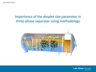
- 1. Low shear basics Importance of the droplet size parameter in three-phase separator sizing methodology
- 2. Low shear basics Gravity separator working principle • Separators are used to segregate gas from liquid and/or one liquid from another, such as water from oil. • Two factors are necessary to induce segregation: 1) process fluids must be insoluble in each other 2) process fluids must be different in density. • Gravity separation uses the force balance of gravity, buoyancy and drag acting on the dispersed droplets, which yields in terminal settling velocity of the droplet in: Liquid phase: 𝑣𝑡 = 𝑔∙𝑑2∙(𝜌 𝑐−𝜌 𝑑) 18𝜇 𝑐 Gas phase: 𝑣𝑡 = 4∙𝑔∙𝑑∙(𝜌 𝑙−𝜌 𝑔) 3∙𝐶 𝑑∙𝜌 𝑔 0,5
- 3. Low shear basics Separator types • Based on the geometry: – Horizontal separators – Vertical separators – Spherical separators (seldom used) • Based on phase separation: – 2 phase separators (gas-liquid / oil-water) – 3 phase separators (gas, oil, and water) • Based on operating pressure: – High pressure separators ( ̴1500psig/100barg) – Intermediate pressure separators ( ̴750psi/50barg) – Low pressure separators ( ̴250psi/17barg)
- 4. Low shear basics Separator internals Separator performance mainly depends on the type of internals that can be found in main separator parts: - Inlet zone: various inlet diverter internals change momentum of the fluid, thus causing initial separation of liquid from the gas. - Gravity/Coalescing zone: mesh/plate/vane/matrix packs promote the gravity separation of the dispersed droplets from the continuous phase as the fluids flowing from the inlet section to the outlet nozzles. - Gas outlet zone: various mist type extractors catch small-sized liquid droplets not separated from the gas stream. Droplets are allowed to coalesce and fall down by gravity to the liquid phase.
- 5. Low shear basics Separator sizing constraints Following constraints determine the vessel’s diameter-length ratio combination for the optimal performance: • Gas capacity constraint (allow the liquid droplets to fall from the gas phase to the liquid volume). Gas has to meet certain dryness specification. • Separation of water from oil (allow the water droplets to settle from the oil phase into the water phase). Oil has to meet certain specification for content of basic sediments and water (BS&W). • Separation of oil from water (allow the oil droplets to rise from the water phase into the oil phase). Water has to meet certain purity specification. The minimum droplet diameter (liquid droplet in gas phase/oil droplet in water phase/water droplet in oil phase) to be removed determines largely the separator design. Depending on the relative ratio of the different phases aforementioned constraints will govern the separator design.
- 6. Low shear basics Separator sizing methods Various sizing techniques are employed by engineers in order to design proper separation equipment. Some sizing methods give simple and robust estimations, while others are more complicated, but provide information for design conditions of downstream equipment. Following sizing methods are available in the literature: • Retention time theory. • Droplet settling (cut-off diameter) theory. • Fluid carry over specification combined with the estimated droplet size distribution and associated dispersed phase volumes.
- 7. Low shear basics Retention time method • For a horizontal separator relationship of vessel diameter 𝐷 and effective length 𝐿 𝑒𝑓𝑓 can be found as: 𝐷2 ∙ 𝐿 𝑒𝑓𝑓 = 𝑄 𝑤∙𝑡 𝑟𝑤+𝑄 𝑜∙𝑡 𝑟𝑜 𝐶∙𝐹 𝑙 • Input data required: – Oil and water flow rates, 𝑄 𝑜, 𝑄 𝑤 – Selected retention times for oil and water, 𝑡 𝑟𝑜, 𝑡 𝑟𝑤 For water and oil retention time determination, batch test is required. If not possible, guidance for the recommended retention times for various operating conditions can be found in standard API 12J.
- 8. Low shear basics Retention time method - pitfalls - Results of batch testing for retention time has no guarantee for the separation performance in a real plant. - API recommendations for retention time are too vague and are not customized based on actual feed characteristics. - Retention time method cannot provide any estimation of carry over fraction to the outlet streams. - Effect of separator internals is not taken into account.
- 9. Low shear basics Droplet settling method • For gas-liquid separation relationship of vessel diameter 𝐷 and effective length 𝐿 𝑒𝑓𝑓 can be found as: 𝐿 𝑒𝑓𝑓 ∙ 𝐷2 ∙ 𝐹𝑔 ℎ 𝑔 = 𝐶 ∙ 𝑇 ∙ 𝑍 ∙ 𝑄 𝑔 𝑃 𝜌 𝑔 𝜌𝑙 − 𝜌 𝑔 ∙ 𝐶 𝐷 𝑑 𝑑 1/2 (Subscripts «𝑔» and «𝑙» are for gas and liquid phases respectively) • For liquid-liquid separation relationship of vessel diameter 𝐷 and effective length 𝐿 𝑒𝑓𝑓 can be found as: 𝐿 𝑒𝑓𝑓 ∙ 𝐷2 ∙ 𝐹𝑐 ℎ 𝑐 = 𝐶 ∙ 𝑇 ∙ 𝑍 ∙ 𝑄 𝑐 𝑃 𝜌 𝑐 𝜌 𝑑 − 𝜌 𝑐 ∙ 𝐶 𝐷 𝑑 𝑑 1/2 (Subscripts «𝑐» and «𝑑» are for continuous and dispersed phases respectively) • Input data required: – Oil, water, gas flow rates, 𝑄 𝑜, 𝑄 𝑤, 𝑄 𝑔 – Selected cut-off droplet diameter 𝑑 𝑑 to be separated.
- 10. Low shear basics Droplet settling method - pitfalls - Cut-off droplet diameter to be separated assumes that all the dispersed droplets above cut-off diameter will be separated. - In order to estimate a carry over fraction, droplet size distribution curve and estimation of volume percent of the dispersed phase are required. - Quantification of these data requires a number of assumptions to be made. Additionally, these data depend on numerous variables which change with time, such as level of turbulence caused by upstream equipment, gas-liquid ratio and water cut, as well as fluid temperature. - Effect of separator internals is not taken into account.
- 11. Low shear basics Fluid carry over method • This methodology utilizes the desired outlet fluid quality specifications combined with estimated inlet droplet size distributions and associated estimated dispersed phase volumes. • These calculations are more complex and details can be found in following papers: – Song, J.H., Jeong, B.E., Kim, H.J. et.al. «Three-Phases Separator Sizing Using Drop Size Distribution», OTC20558. https://doi.org/10.4043/20558-MS – Bothamley, M. «Gas/Liquid Separators: Quantifying Separation performance», part 1-3. Oil & Gas Facilities. https://doi.org/10.2118/0813-0021-OGF – Bothamley, M. «Quantifying Oil/Water Separation Performance in Three- Phase Separators» Part 1. https://spe.org/en/print-article/?art=2830
- 12. Low shear basics Fluid carry over process methodology Gas-liquid separation Liquid-liquid separation 1) With an assumption of the annular gas-liquid flow regime in the pipe upstream the separator, liquid entrainment fraction can be calculated by entrainment correlation. 1) Estimate the amount of dispersed water in oil phase and the amount of oil dispersed in water phase. Flow pattern map can be employed to estimate flow regime and to make predictions on amount of dispersed phase. Another approach mentioned in the literature is to split total entrained volume for the dispersed water and oil into the same ratio as the original oil-water ratio. Both methods provide rather qualitative estimation. 2) Estimate droplet size distribution based on shearing and coalescence of the choke and the pipe segment between the choke and the separator. 2) Calculate droplet size distribution based on flow conditions and turbulent energy dissipation rate. An upper-limit log normal distribution or Rosin-Rammler distribution is recommended in the literature for this purpose. With the absence of experimental data some suggestions for values of the fitting parameters can be found in the literature. 3) Calculate terminal velocity of liquid drops in gas phase using Souders-Brown type of equation. 3) Calculate terminal velocity of dispersed phase droplets using Stoke’s Law. 4) With input gas flow rate, liquid carry over specification and the gas-liquid interface level calculate retention time needed for entrained liquid drops to separate from the gas phase down to desired level. 4) With input oil and water flow rates, phase carry over specification, and the gas-liquid interface level calculate retention time needed for dispersed droplets to rise/settle to the phase interface. 5) Using input flow rate for three phases, required retention times for each phase to separate down to a desired carry over level, and adjusting the gas-liquid interface level it is possible to calculate the optimal dimension for the three-phase separator.
- 13. Low shear basics Fluid carry over method – Hysys simulation – Hysys process simulation software allows to model real separator performance with a carry over setup. – With a correlation based model the simulator can calculate the expected carry over fractions based on the configuration of the vessel, feed conditions, and the operating conditions. – As an input data Hysys requires the specification of the dispersed phase volumes and the dispersed droplet size distribution. – The ProSeparator correlation allows to calculate liquid carry over into the gas phase based only on the inlet gas flow rate, the gas-liquid physical properties, and the inlet pipe size. – Hysys can not simulate performance of the separator internal devices (coalescer, mesh pad, etc). The only input geometry parameters are the nozzles design, the weir and the boot geometry specifications.
- 14. Low shear basics Importance of fluid specification • In recent years more and more attention has been paid to the specification of the droplet size distribution and the amounts of dispersed fractions in oil, water and gas phases. • Separator performance is greatly dependent on these parameters. • Attention should be paid to the sources of shear that generate small droplets and increase the fractions of the dispersed phases. • When designing a process facility, a holistic approach is beneficial regarding the choice of the correct equipment. • The low shear type equipment must be considered where droplet shearing is expected. • Analysis of the droplet size distribution and the levels of the carry over fractions in the outlet streams can be used as a debottlenecking technique for optimizing the separator performance.
- 15. Low shear basics Effect of equipment on droplet size The smallest droplets present the greatest challenge to the separator performance. Thus, it is important to maintain the droplets of the dispersed phase as large as possible. When production fluids flow from the reservoir, they naturally encounter turbulent zones, such as casing perforations, bends, choke and control valves. Shearing of the droplets occurs there. However, when fluids flow in the straight pipe, coalescence is enabled. The effect of different types of control valves on average droplet size of the dispersed oil in water is shown: (Graph courtesy of Typhonix AS)
- 16. Low shear basics Effect of equipment on droplet size Due to higher average droplet sizes in the fluid flow the separator efficiency can be improved. The benefits gained by maintaining higher droplet sizes with a low shear control valve upstream a separator allow following: - Lower retention time needed for the specified carry over fraction. - Reduced carry over fraction with given retention time. - Chemicals reduction is possible if they are used in the process. (Qualitative estimate)
- 17. Low shear basics Effect of equipment on droplet size The correct choice of pump can be critical for the droplet shearing. The effect of different types of pump on the average oil droplet size in produced water can be seen from the graph: (Graph courtesy of Typhonix AS)
- 18. Low shear basics Additional sources To read more in detail about retention time and droplet settling separator sizing methods: Arnold, K.E., Koszela, P.J.: Droplet-Settling vs. Retention-Time Theories for Sizing Oil/Water Separator. 1990. SPE Production Engineering. V05 Issue 01. https://doi.org/10.2118/16640-PA Boukadi, F., Singh, V., Trabelsi, R. et.al.: Appropriate Separator Sizing: A Modified Stewart and Arnold Method. 2012. Modelling and Simulation in Engineering. Volume 2012. https://doi.org/10.1155/2012/721814 http://petrowiki.org/PEH:Oil_and_Gas_Separators#Separator_Sizing