SlideShare a Scribd company logo
1 of 9
Download to read offline
Foaming and polymeric agents used in tests for the conditioning of soils during the progress of excavation
work for a tunnel with a mechanized shield of the TBM-EPB type
by Lamanna Luigi Franco (*)
A) - Introduction
When excavating a metropolitan or railway tunnel, especially in the subsoil of large cities, using a mechanized shield of
the TBM-EPB or TBM-Slurry type (where large quantities of bentonite mud are used in the latter), a particular attention to
geotechnical problems, because it is necessary to guarantee the stability of the excavation face by maintaining a pressure
on it, to avoid the collapse of the face itself with the consequences of subsidence such as landslides or elastic-plastic
deformations of the soil.
This can only be done by controlling the balanced confinement pressure that can be carried out, using additives in front
of the excavation face, whatever the geological and stratigraphic, hydrogeological and geotechnical conditions of the soil.
Photo 01 – TBM-EPB, a) schematic diagram of EPB machine used in Beijin, China Metro Xijiao line; b) in the figure of the TBM-EPB, bottom right,
schematic of the header gate that connects the soil chamber and the screw conveyor. (Earth pressure balance shield tunneling in sandy
gravel deposits: a case study of application of soil conditioning, Bulletin of Engineering Geologyand the Environment, Springer-Verlag
GmbH Germany, part of Springer Nature 2020)
Before starting the excavation with an EPB it is necessary to define in detail the working pressures along the entire construction
line of a tunnel. This consists in setting the stability limit of the excavation face and the maximum working pressure that can
produce settlements (subsidence) or lifting.
To avoid this, it is necessary to evaluate and take into account some excavation parameters or, in more detail, the coefficients
in order to define the pressure limits (upper and lower) to be respected during excavation for the good functioning of thecutter.
Therefore, the only valid element known, up to now, to counter this phenomenon is to create a plastic paste with the excavation
soil in the TBM-EPB excavation chamber, as well as helping to maintain the same pressure, also at the inside the auger where
the latter, with the soil-vine interaction during the material extrusion process, allows a speed of unloading of the excavated
material itself.
Photo 02 – Slurry Shield Machine (Herrenknecht)
All this takes place with the sole purpose of maintaining a constant magnitude of the pressure. For the successful operation of
the TBM-EPB, everything depends on the TBM technician (driver), on his preparation and experience, because he is the only
one who can choose to reduce the thrust on the shield and regulate, fundamental thing, also the angular velocity of the cochlea.
All photos illustred are copied from the WEB
All
photos
illustred
are
copied
from
the
WEB
B) - Brief description of the operating principle of a TBM-EPB
The operating principle of a shielded TBM-EPB is very simple. Shielded TBMs, those that keep the excavation face under
pressure, commonly called EPBs, are used when very difficult stress-deformation conditions of the ground occur; that is, in
those situations in which the mechanical contrast provided by the milling head alone cannot avoid the relaxation of the
excavation face (collapse).
Photo 03 – Schematic view of producing and injecting foam in EPB-TBM Soil
Conditioning, Herrenknecht & Rehm 2002 (ITA/AITES)
A feature of these types of cutters is that the front of the cutter head has openings to allow the excavated soil to enter the
pressure chamber, these openings are of the order of 20-30% of the total surface.
The advancement of the cutter allows the material and fine parts to enter this diaphragm that is created between the excavation
face and the milling head, thus allowing the thrust of the hydraulic pistons to be transferred to the shield, exerting on the front
of I dig the pressure necessary to counteract that exerted by the ground.
The shield of an EPB type has the function of counteracting the thrusts of the ground, keeping the excavation intact and at the
same time securing the personnel in charge; in addition, the EPB shield prevents, through a system of gaskets, continuously fed
by special sealing greases, the entry of any water encountered (Main Bearing Greases).
In addition, in the final part of the EPB shield, the final lining of the tunnel is mounted, generally consisting of a series of
prefabricated segments made of reinforced concrete put in place by a rotating system placed inside the shield.
The last ring (concrete segment) mounted is used as a contrast by the thrust pistons for the advancement of the TBM.
Finally, the extrados of the cladding, again the one made of prefabricated segments, the annular space between the excavation
profile and the extrados of the cladding, is injected with a mortar or mortar under pressure, commonly called PEA-GRAVEL,
which is used to seal and contrast the tunnel against the ground.
I would like to point out that some operators in the sector, who use very advanced technologies and methodologies, instead of
injecting Peal-Gravel behind the segments (in the annular space between the excavation profile and the extrados of the coating),
inject special resinous silicate formulations mineral-organic which also have the task, in addition to contrasting the rock mass
with the final lining of the tunnel, to avoid for many years (at least 50 years) the infiltration of water inside the tunnel, at the
same time avoiding degradation of the reinforced concrete lining (always the one made of prefabricated segments), both
internally and externally, guaranteeing its "durability" which, as we all know, can be influenced by numerous factors that are
commonly classified as chemical, physical and mechanical .
Remember that reinforced concrete can be damaged by expansion, water, physical corrosion, due to physical and chemical
damage, with a rapid process of degradation because it is exposed to these stimuli.
C) - Illustration of our experimentation conducted
As I have already said, in order to condition the ground it is necessary to create a plastic paste with this, in particular the one
that ends up in the excavation chamber, therefore, during the normal excavation we carried out an experiment, directly in an
excavation site, on the advancement of the construction of a service tunnel (pilot hole) using an EPB (EARTH PRESSURE
BALANCE), using the same excavation material as a test.
All
photos
illustred
are
copied
from
the
WEB
During the execution of the tests, a foaming agent FOAM was injected on the excavation face, in different percentages, by
means of special nozzles placed on the tiller head, with the function of fluidizing the soil that was excavated and at the same
time the resulting soil, which ended up in the chamber excavation, so as to form the layer of fluidized soil in its entire mass
forming the plastic paste.
Furthermore, the excavated material was mixed and accumulated under pressure, not only in the clearing chamber (excavation
chamber), but also in the auger which removed it in a fluid and controlled manner.
Photo 04 – Pressure of the supporting soil paste in the excavation chambre of anTBM-EPB counteracting the water and
earth pressure the face. (Lisa Mori, 2016, Colorado School of Mines, DPT of Mining Engineering)
In fact, these FOAM foaming agents, used for the conditioning of the ground (such as surfactants and polymers), are all mono-
component and non-reactive because their use, in particular for mechanized excavation by TBM-EPB, this occurs directly
through of the nozzles placed in front of the cutter head, in the excavation chamber and also present in the auger. In any case,
the entire pumping system is placed inside the TBM.
Photo 05 - Illustration of the foam generation system inside a TBM-EPB
All this also allows the constant control of the confinement pressure exerted on the excavation face and the coordinating the
thrust of the cutter in advance as well as the extraction speed of the auger.
For the first time, we tried to carry out various tests on site, trying to simulate borderline cases, using mud and water jets,
simulating an underground water circulation source, creating a composition of soil, similar to how it can be presented in a real
limit execution phase, using strong jets of water, at high pressure, which had the ability to break up the most resistant soil; this
to simulate operating in those terrains not suitable for the shield.
Dear colleagues, as you can imagine, this simulation was not easy to solve, even having taken great care in modifying and
equipping ourselves to simulate risks similar to those of reality, as if we were in the presence of difficult terrain, with large
quantities of water, and without having to resort to particular known techniques.
All
photos
illustred
are
copied
from
the
WEB
All
photos
illustred
are
copied
from
the
WEB
D) - Why it is important to maintain the pressure inside the "excavation chamber"
An excess of operating pressure can represent a destabilizing effect while, a pressure lower than the equilibrium limit, can cause
the collapse of the face and cause surface subsidence (subsidence) of the ground following the excavation of tunnels, such as
underground or underground tunnels underground mines.
But I want to remind you that the effect of the pressure applied to the machine tends to reduce the effect of the extent of the
subsidence (subsidence) because there is a continuous monitoring and control system inside the TBM-EPB.
Photo 06 - Average composition for a normally used foam
On the other hand, too high a pressure, excessively increases the stresses on the machine, decreases the forward speed and
can in turn cause instability as it can generate the lifting of the ground above the excavation trajectory in correspondence with
the construction of a superficial line tunnel underground.
D.1) - APPLICABILITY OF THE EPB METHOD
Therefore, for an EPB cutter to function optimally, the excavated material must have the following characteristics:
- good plastic deformability;
- low internal friction angle;
- low permeability.
In clayey-sandy and clayey-loamy soils, with a light consistency, the presence of this feature is optimal for the use of EPB type
shields.
However, it is difficult to find a material that is naturally only suitable for excavating in EPB mode, so steps are required to make
the soil suitable for excavation:
- the excavated materials are generally mixed with additives (chemical foams and polymers).
Otherwise the fluid will not be able to have a uniform movement, and therefore can cause an arc effect and a porosity inside
the diaphragm through which the water, usually present at the front, is able to flow freely, thus determining a possible collapse
of the front itself.
Therefore it is necessary to ensure a plastic excavation terrain, and this is made possible by using chemical agents (foams,
stabilizers, anti-aggregating agents), this operation is called conditioning of the soil which is the test and the object of this
report. Conditioning agents are usually injected from the shield, into the excavation chamber and into the cochlea.
Therefore, the correct behavior of the foaming agent must be evaluated in advance on the basis of two performance indicators:
the foaming and stability of the foam, which are quantified by the FER (Foam Expansion Ratio) and by the "half-life" period,
the time required for the foam to drain 50% of the generator liquid used (EFNARC, 2005).
Based on the minimum FER required, a concentration (Cf = 1.5 - 5%) of the foaming agent is recommended to develop adequate
conditioning of the soil with a consumption between 0.5 - 2 Kg / m3.
CHEMSPERSE
- CHEMSURF-A-22
- CHEMSURF-H-38
- CHEMCRYL
ADDITIVE 2
ADDITIVE 1
WATER
SOLUTION
AIR
FOAM
INJECTED
AVERAGE COMPOSITION FOR A NORMALLY USED FOAM:
- CHEMSURF-A-22 AND CHEMSURF-H-38 : 0.5 – 1 %
-- WATER: 5 – 10 %
-- AIR: 90 -95 %
-- CHEMCRYL (EVENTUAL): < 0.1 %
FOAMING AGENT CAN HAVE INSIDE A SMALL AMOUNT OF POLYMER TO
STABILIZE THE FOAM BUBBLES
FER
FIR
To further develop the soil conditioning scheme, further tests, such as Slump Tests and Hydraulic Permeability, must be
conducted to evaluate the homogeneity, abrasiveness, workability and hydraulic permeability of the conditioned soil.
On the basis of these further indicators, related to performance, a FIR (Foam Injection Ratio) injection ratio of the foaming
agent is determined which usually, the latter indicator, is indicated by the TBM-EPB conductors between 30% and 60 %.
Below, I want to briefly indicate how you get there you have FER and FIR values, of the two main properties of the foam,
according to EFNARC 2005, which are:
- FER: is the expansion ratio of the foam is the ratio between the volume of the foam at the operating pressure and the volume
of the foam solution.
FER = V foam / V foam solution
The expansion ratio of the foam should be between 5-30.
If the FER value is high; the foam generated must be drier.
Drier foam should be used in moist soil and vice versa.
- FIR: the foam injection ratio is the ratio between the volume of the foam at the operating pressure and the volume of the soil
in situ to be excavated.
FIR = 100 x V foam / V soil
The foam injection ratio should be between 20-80% but in most cases it is between 30-60%.
- However, in order to have information on the best FIR value, laboratory tests should be carried out;
- while, I would like to point out that the water content of the soil and the water content of the injection are important.
In fact, the type of foam is determined by the type of excavation soil encountered during the excavation phase. Therefore foams
must be classified into three types; A, B and C (EFNARC, 2005):
FOAM TYPE A:
- The dispersion capacity is high (breaking of clay bonds)
- Good coating ability (reduces swelling effects)
FOAM TYPE B:
- For general use
- Medium stability
FOAM TYPE C:
- High stability
- Anti-segregation properties (develop and keep the impermeable ground cohesive)
However, to ensure the effectiveness of the soil conditioning schemes, which are based on the foaming agents used, it is
important to verify with in situ tests and observations (including slump tests and visual inspections), samples of conditioned
soil, collected on site, for satisfy all the necessary geological and geotechnical conditions.
E) - Example of use of surfactants and a polymer
To enter into the merits of the tests, the following products were used: a foaming agent formulated with particular anionic,
biodegradable surfactants called CHEM-SURF-H-38; a liquid dispersing agent formulated with particular polycarboxylates called
CHEM-SPERSE; and a synthetic liquid polymer, formulated with special acrylamide / sodium acrylate copolymers called CHEM-
CRYL to be used separately or in combination.
Tab. 01 – Foam classification and application area (EFNARC, 2005)
The products that I take the liberty of suggesting and that can be used for ground conditioning, are those developed by the
company CHEMIX s.r.l., of Golasecca (Varese), an Italian chemical industry, in collaboration with myself. Products designed with
the aim of finding the right proportion to stabilize any type of soil under consideration.
This solution, that of the two CHEM-SURF-H-38 + CHEM-CRYL or CHEM-SPERSE + CHEM-CRYL products, called FOAM agents, is
the injection solution to be done at the excavation face, in the excavation chamber and in the auger. It can vary, depending on
the ground conditions, even equal to 50% of the excavated volume.
However, the proof of use of the FOAM was based on three fundamental operations:
- the development of the percentages of product to create asoil treated to make it become quite fluid as mud (water-surfactant-
polymer);
- identify the pressure to be exerted on the mud to stabilize the excavation face;
- identify the pressure to be applied on the ground that has become mud to control the excavation by operating both on the
auger and on the thrust cylinders (in our case only one thrust cylinder is sufficient) to maintain balanced weights and volumes.
In general, the products used during the soil treatment tests produced the following effects:
- the Foams (type CHEM-SURF-H-38 and CHEM-SPERSE):
they have maintained the stability of the face, with an increased capacity for plastic deformation of the ground (foam that is
transformed into a homogeneous mousse), as well as a reduction in internal friction and the torque of the cutting head.
- the Polymer (type CHEM-CRYL):
it has maintained the stabilization of the soil and of the foams themselves, and water retention (ideal to be used even in the
presence of large quantities of water).
Finally, type CHEM-SPERSE has proved to be of interest as a ready-to-use product, and finds and can be used as:
Photo 07 – Slump test - On the basis of numerous experiences developed in the laboratory with the execution of specific research aimed at defining of a
"test protocol" of the "the conditioned medium" and on the basis of indications of "technical standards", in this study the "indicator, the drop test” to the
Abrams cone (Slump Test) for the purpose of preliminarily characterize the “conditioned medium”. In test the following technical aspects were analyzed:
- presence of a condition of the soil plasticity (qualitative observation);
- falling to the cone of about 15-20cm;
- reduced release of ”Water + Foam" from the mass of "the conditioned medium" after the test.
- Dispersing agent:
that is, to disperse / break up the strongly cohesive tabular structure of well-consolidated clayey soils, with a consequent
decrease in their viscosity. Furthermore, this agent facilitates the resumption of excavation following stops or prolonged
interruptions.
I would like to underline that the choice of the specific product or combination of products, the identification of the various
application parameters in relation to the product (concentration of the additive in the aqueous solution, rate of expansion of
the foam, rate of injection into the soil) and the method of advancement to be followed depends, as already mentioned, on the
geo-mechanical characteristics of the ground crossed during the excavation.
Photo 08 - Graphic scheme - Conditioning layout showing injection at cutter face, working chamber and screw conveyor
E.1) - TECHNICAL CHARACTERISTICS OF THE PRODUCTS USED DURING THE TEST
E.1.1) - CHEM-SURF-H-38
- Density 1.04  0.02 kg / l
- pH (for 1% solution) 7
- Total water solubility
YES
NO
NO
OPTIMAL CONDITIONING NOT ACCEPTABLE
CONDITIONING, TOO FLUID
NOT ACCEPTABLE
CONDITIONING, TOO DRY
All photos illustred are copied from the WEB
FIR FER
The dosage of the product diluted in water varies from 0.5 to 2% by weight.
E.1.2) - CHEM-SPERSE
- Density 1.26  0.02 kg / l
- pH 7.5  0.2
- viscosity 300. 50 mPas
- Total water solubility
The product is formulated to be ready for use and ranges from 0.05 to 1.5% of the volume of the excavated soil.
E.1.3) - CHEM-CRIL
- Density 1.05  0.02 kg / l
- pH (for a 5% solution) 6 - 8
- viscosity 1.000  400 cPs
Its dosage varies from 2 to 4 kg per 1,000 liters of water (the product must be added to the water under constant stirring 20-30
minutes before the introduction of the foaming agent).
Photo 09 - Spray test on the cutter head of foaming agent formulated with
particular biodegradable anionic surfactants, S.E.L.I. Rome, Italy
F) - Conclusion
The tests carried out on site, with the use of FOAM, had the purpose of letting us know which parameters are necessary between
weight and volumes of earth excavated and removed to guarantee the non-occurrence of collapses or superficial subsidence
(subsidence) to obtain the characteristics of impermeability and plasticity, which are strictly correlated to the porosity of the
soil used during the excavation phase.
In general, by carrying out various tests, and finding ourselves in the presence of different types of soil, we have seen that the
theoretical average quantity of FOAM that must be injected is equal to 300 l / m3. Furthermore, we verified whether the effect
deriving from the compressibility of the foam (FOAM) reduces the pressure fluctuations on the excavation face, a test that was
positive and necessary for the operators to have total control of the TBM-EPB.
Finally, we also saw and evaluated that the foam not only allowed us to increase the workability of the excavated material and
to reduce its permeability, because it was more fluid, but what is more interesting it prevents the adhesion of the soil-foam on
the metal parts of the internal walls of the excavation chamber and auger eliminating the risk of obstructions.
And to finish, we verified that the use of products, such as those mentioned above, allowed us to create a stable foam over
time due to the foaming power of their composition and molecular structure. Therefore, I would like to point out that the
comments reported in this report refer to real tests carried out directly on a construction site of a tunnel and not comments on
tests carried out in the laboratory, which are usually made on samples of reduced material, with the result of having indicative
data and it becomes necessary, during the excavation phase, to be verified directly on the TBM-EPB.
All photos illustred are copied from the WEB
(*) Luigi Franco, LAMANNA
Independent Technical Consultant in the sector of Tunneling, Mining and Underground Technology
Presidente of the Fondazione Internazionale di Centro Studi e Ricerche, ONG
132, via dei Serpenti, 00184 ROMA, Italia, U.E.
E-mail: lamannaluigifranco1@gmail.com
LinkedIn: Lamanna Luigi Franco
DISCLAIMER
This PDF is an amateur product which can not be applied Article. 5 of the Italian Law No 8 February 1948 n. 47, since the updating of the information contained in
it has no regular periodicity (art. 1 paragraph 3, of the law 7 March 2001 n. 62).
This PDF is not representing a journalistic head or whatever and posts published are intended to stimulate discussion and the technical study, criticism and freedom
of expression of thought, in the manner and within the terms permitted by current Italian legislation.
How known all over the world the material published on the Internet is public domain. Nevertheless, if someone would recognize their own material with Copyright
and did not want to see it published on this PDF, it only has to give notice to the manager and will be immediately eliminated.
We declare, moreover, they are not responsible for the comments included in the post. Any reader comments, damaging the image or repute of third persons, are
not to be attributed to us, not even if these are expressed in an anonymous or encrypted.

More Related Content

What's hot

Contemporary Grouting Equipment
Contemporary Grouting EquipmentContemporary Grouting Equipment
Contemporary Grouting EquipmentMladen Zahariev
 
Different grout injection methods
Different grout injection methodsDifferent grout injection methods
Different grout injection methodsBMC Microfine
 
Cut and cover_sections
Cut and cover_sectionsCut and cover_sections
Cut and cover_sectionsjuwes
 
Permeation grouting for remediation of dam cores
Permeation grouting for remediation of dam coresPermeation grouting for remediation of dam cores
Permeation grouting for remediation of dam coresUjwal Ujwal
 
Wk 1 2_substructure_dewatering_bw
Wk 1 2_substructure_dewatering_bwWk 1 2_substructure_dewatering_bw
Wk 1 2_substructure_dewatering_bwjuwes
 
Practices in Planning, Design and Construction of Head Race Tunnel of a Hydro...
Practices in Planning, Design and Construction of Head Race Tunnel of a Hydro...Practices in Planning, Design and Construction of Head Race Tunnel of a Hydro...
Practices in Planning, Design and Construction of Head Race Tunnel of a Hydro...Mohit Shukla
 

What's hot (11)

Cut and cover
Cut and coverCut and cover
Cut and cover
 
Grout curtain
Grout curtainGrout curtain
Grout curtain
 
Contemporary Grouting Equipment
Contemporary Grouting EquipmentContemporary Grouting Equipment
Contemporary Grouting Equipment
 
Different grout injection methods
Different grout injection methodsDifferent grout injection methods
Different grout injection methods
 
Cut and cover_sections
Cut and cover_sectionsCut and cover_sections
Cut and cover_sections
 
Methods of Dewatering
Methods of DewateringMethods of Dewatering
Methods of Dewatering
 
Permeation grouting for remediation of dam cores
Permeation grouting for remediation of dam coresPermeation grouting for remediation of dam cores
Permeation grouting for remediation of dam cores
 
Characterization of soil conditioning for mechanized tunnelling
Characterization of soil conditioning for mechanized  tunnelling Characterization of soil conditioning for mechanized  tunnelling
Characterization of soil conditioning for mechanized tunnelling
 
Wk 1 2_substructure_dewatering_bw
Wk 1 2_substructure_dewatering_bwWk 1 2_substructure_dewatering_bw
Wk 1 2_substructure_dewatering_bw
 
Practices in Planning, Design and Construction of Head Race Tunnel of a Hydro...
Practices in Planning, Design and Construction of Head Race Tunnel of a Hydro...Practices in Planning, Design and Construction of Head Race Tunnel of a Hydro...
Practices in Planning, Design and Construction of Head Race Tunnel of a Hydro...
 
Grouting n gunintung
Grouting n gunintungGrouting n gunintung
Grouting n gunintung
 

Similar to 2021_ENG_DIC_SOIL CONDITIONING.pdf

Jet-grouting Technology
Jet-grouting TechnologyJet-grouting Technology
Jet-grouting TechnologyMECandPMV
 
Comprehensive report on Tunneling @ Abu Hamour Project_Qatar
Comprehensive report on Tunneling @ Abu Hamour Project_QatarComprehensive report on Tunneling @ Abu Hamour Project_Qatar
Comprehensive report on Tunneling @ Abu Hamour Project_QatarPallav Sharma
 
124 مبادرة #تواصل_تطوير -المركبات البوليمرية الجيوتقنية و تطبيقاتها في الهندس...
124 مبادرة #تواصل_تطوير -المركبات البوليمرية الجيوتقنية و تطبيقاتها في الهندس...124 مبادرة #تواصل_تطوير -المركبات البوليمرية الجيوتقنية و تطبيقاتها في الهندس...
124 مبادرة #تواصل_تطوير -المركبات البوليمرية الجيوتقنية و تطبيقاتها في الهندس...Egyptian Engineers Association
 
Well_Completions.pdf
Well_Completions.pdfWell_Completions.pdf
Well_Completions.pdfAihamAltayeh1
 
Geosynthetics in civil engineering (multifunctional uses of geosynthetics in ...
Geosynthetics in civil engineering (multifunctional uses of geosynthetics in ...Geosynthetics in civil engineering (multifunctional uses of geosynthetics in ...
Geosynthetics in civil engineering (multifunctional uses of geosynthetics in ...Super Arc Consultant
 
Road pavements-of-cement-concrete
Road pavements-of-cement-concreteRoad pavements-of-cement-concrete
Road pavements-of-cement-concreteMylene Delmoro
 
Road pavements-of-cement-concrete
Road pavements-of-cement-concreteRoad pavements-of-cement-concrete
Road pavements-of-cement-concreteMylene Delmoro
 
Design and Analysis of Impregnation Chamber Used In Vacuum Pressure Impregnat...
Design and Analysis of Impregnation Chamber Used In Vacuum Pressure Impregnat...Design and Analysis of Impregnation Chamber Used In Vacuum Pressure Impregnat...
Design and Analysis of Impregnation Chamber Used In Vacuum Pressure Impregnat...IOSR Journals
 
applsci-10-07515-v2.pdf
applsci-10-07515-v2.pdfapplsci-10-07515-v2.pdf
applsci-10-07515-v2.pdfEREED1
 
Field Failure Analysis of DTH Hammer Bit
Field Failure Analysis of DTH Hammer BitField Failure Analysis of DTH Hammer Bit
Field Failure Analysis of DTH Hammer BitIRJET Journal
 
20150906 Operational analysis_final
20150906 Operational analysis_final20150906 Operational analysis_final
20150906 Operational analysis_finalSewerin Sabew
 
Hybrid epb tunnelling in rio de janeiro 2015
Hybrid epb tunnelling in rio de janeiro 2015Hybrid epb tunnelling in rio de janeiro 2015
Hybrid epb tunnelling in rio de janeiro 2015Abner Silva
 

Similar to 2021_ENG_DIC_SOIL CONDITIONING.pdf (20)

Jet-grouting Technology
Jet-grouting TechnologyJet-grouting Technology
Jet-grouting Technology
 
Comprehensive report on Tunneling @ Abu Hamour Project_Qatar
Comprehensive report on Tunneling @ Abu Hamour Project_QatarComprehensive report on Tunneling @ Abu Hamour Project_Qatar
Comprehensive report on Tunneling @ Abu Hamour Project_Qatar
 
Tunnel Boring Machines
Tunnel Boring Machines  Tunnel Boring Machines
Tunnel Boring Machines
 
124 مبادرة #تواصل_تطوير -المركبات البوليمرية الجيوتقنية و تطبيقاتها في الهندس...
124 مبادرة #تواصل_تطوير -المركبات البوليمرية الجيوتقنية و تطبيقاتها في الهندس...124 مبادرة #تواصل_تطوير -المركبات البوليمرية الجيوتقنية و تطبيقاتها في الهندس...
124 مبادرة #تواصل_تطوير -المركبات البوليمرية الجيوتقنية و تطبيقاتها في الهندس...
 
Some brief considerations on the machanized evolution of metropolitan tunnel ...
Some brief considerations on the machanized evolution of metropolitan tunnel ...Some brief considerations on the machanized evolution of metropolitan tunnel ...
Some brief considerations on the machanized evolution of metropolitan tunnel ...
 
2022_ENG_TBM
2022_ENG_TBM2022_ENG_TBM
2022_ENG_TBM
 
Well_Completions.pdf
Well_Completions.pdfWell_Completions.pdf
Well_Completions.pdf
 
Temeltas Jet Grout
Temeltas Jet GroutTemeltas Jet Grout
Temeltas Jet Grout
 
Vacuum concrete
Vacuum concreteVacuum concrete
Vacuum concrete
 
Geosynthetics in civil engineering (multifunctional uses of geosynthetics in ...
Geosynthetics in civil engineering (multifunctional uses of geosynthetics in ...Geosynthetics in civil engineering (multifunctional uses of geosynthetics in ...
Geosynthetics in civil engineering (multifunctional uses of geosynthetics in ...
 
ATS11-05415
ATS11-05415ATS11-05415
ATS11-05415
 
Road pavements-of-cement-concrete
Road pavements-of-cement-concreteRoad pavements-of-cement-concrete
Road pavements-of-cement-concrete
 
Road pavements-of-cement-concrete
Road pavements-of-cement-concreteRoad pavements-of-cement-concrete
Road pavements-of-cement-concrete
 
Design and Analysis of Impregnation Chamber Used In Vacuum Pressure Impregnat...
Design and Analysis of Impregnation Chamber Used In Vacuum Pressure Impregnat...Design and Analysis of Impregnation Chamber Used In Vacuum Pressure Impregnat...
Design and Analysis of Impregnation Chamber Used In Vacuum Pressure Impregnat...
 
applsci-10-07515-v2.pdf
applsci-10-07515-v2.pdfapplsci-10-07515-v2.pdf
applsci-10-07515-v2.pdf
 
Field Failure Analysis of DTH Hammer Bit
Field Failure Analysis of DTH Hammer BitField Failure Analysis of DTH Hammer Bit
Field Failure Analysis of DTH Hammer Bit
 
20150906 Operational analysis_final
20150906 Operational analysis_final20150906 Operational analysis_final
20150906 Operational analysis_final
 
Hybrid epb tunnelling in rio de janeiro 2015
Hybrid epb tunnelling in rio de janeiro 2015Hybrid epb tunnelling in rio de janeiro 2015
Hybrid epb tunnelling in rio de janeiro 2015
 
Lecture on Asphalt/Bitumen
Lecture on Asphalt/BitumenLecture on Asphalt/Bitumen
Lecture on Asphalt/Bitumen
 
Tobslak tbyrothane 1 k
Tobslak tbyrothane 1 kTobslak tbyrothane 1 k
Tobslak tbyrothane 1 k
 

More from FONDAZIONE INT.LE CENTRO STUDI E RICERCHE-ONLUS (NGO)

More from FONDAZIONE INT.LE CENTRO STUDI E RICERCHE-ONLUS (NGO) (20)

Use of FOAM in underground works
Use of FOAM in underground works Use of FOAM in underground works
Use of FOAM in underground works
 
Trust Company
Trust CompanyTrust Company
Trust Company
 
Illustration of the various materials for the construction and repair of bridges
Illustration of the various materials for the construction and repair of bridgesIllustration of the various materials for the construction and repair of bridges
Illustration of the various materials for the construction and repair of bridges
 
Study of particular polymeric materials of the 4.0 series for the constructio...
Study of particular polymeric materials of the 4.0 series for the constructio...Study of particular polymeric materials of the 4.0 series for the constructio...
Study of particular polymeric materials of the 4.0 series for the constructio...
 
Geopolitics and the difficulty of procuring raw materials
Geopolitics and the difficulty of procuring raw materialsGeopolitics and the difficulty of procuring raw materials
Geopolitics and the difficulty of procuring raw materials
 
45 years - LAMANNA
45 years -  LAMANNA45 years -  LAMANNA
45 years - LAMANNA
 
2022_TEST INVESTIGATE SOIL CONDITIONING FOR EPB-compressed (1).pdf
2022_TEST INVESTIGATE SOIL CONDITIONING FOR EPB-compressed (1).pdf2022_TEST INVESTIGATE SOIL CONDITIONING FOR EPB-compressed (1).pdf
2022_TEST INVESTIGATE SOIL CONDITIONING FOR EPB-compressed (1).pdf
 
Proyests
ProyestsProyests
Proyests
 
Rock reinforcement and rock support
Rock reinforcement and rock supportRock reinforcement and rock support
Rock reinforcement and rock support
 
Civil Defense Shelters
Civil Defense SheltersCivil Defense Shelters
Civil Defense Shelters
 
New technology for filling and clogging the void that is created in the back ...
New technology for filling and clogging the void that is created in the back ...New technology for filling and clogging the void that is created in the back ...
New technology for filling and clogging the void that is created in the back ...
 
2020_Esempi di intasamento a tergo dei conci in cls prefabbricato-compresso (...
2020_Esempi di intasamento a tergo dei conci in cls prefabbricato-compresso (...2020_Esempi di intasamento a tergo dei conci in cls prefabbricato-compresso (...
2020_Esempi di intasamento a tergo dei conci in cls prefabbricato-compresso (...
 
2021_ENG_Extraction of rare earths from the seabed
2021_ENG_Extraction of rare earths from the seabed2021_ENG_Extraction of rare earths from the seabed
2021_ENG_Extraction of rare earths from the seabed
 
2021_ES_Extracción de tierras raras del fondo marino
2021_ES_Extracción de tierras raras del fondo marino2021_ES_Extracción de tierras raras del fondo marino
2021_ES_Extracción de tierras raras del fondo marino
 
2021_EN_The future miners of the earth
2021_EN_The future miners of the earth2021_EN_The future miners of the earth
2021_EN_The future miners of the earth
 
2020_Repair and reinforcement of the cortical layer of concrete inside a rail...
2020_Repair and reinforcement of the cortical layer of concrete inside a rail...2020_Repair and reinforcement of the cortical layer of concrete inside a rail...
2020_Repair and reinforcement of the cortical layer of concrete inside a rail...
 
2020_Ground stabilization treatments in front of the excavation face of a tun...
2020_Ground stabilization treatments in front of the excavation face of a tun...2020_Ground stabilization treatments in front of the excavation face of a tun...
2020_Ground stabilization treatments in front of the excavation face of a tun...
 
2022_03_PRESENTAZIONE L.L.F..pdf
2022_03_PRESENTAZIONE L.L.F..pdf2022_03_PRESENTAZIONE L.L.F..pdf
2022_03_PRESENTAZIONE L.L.F..pdf
 
2020_Breve descrizione sul metodo NATM.pdf
2020_Breve descrizione sul metodo NATM.pdf2020_Breve descrizione sul metodo NATM.pdf
2020_Breve descrizione sul metodo NATM.pdf
 
2022_ENG_WASTE-compresso (1).pdf
2022_ENG_WASTE-compresso (1).pdf2022_ENG_WASTE-compresso (1).pdf
2022_ENG_WASTE-compresso (1).pdf
 

Recently uploaded

Online food ordering system project report.pdf
Online food ordering system project report.pdfOnline food ordering system project report.pdf
Online food ordering system project report.pdfKamal Acharya
 
DeepFakes presentation : brief idea of DeepFakes
DeepFakes presentation : brief idea of DeepFakesDeepFakes presentation : brief idea of DeepFakes
DeepFakes presentation : brief idea of DeepFakesMayuraD1
 
data_management_and _data_science_cheat_sheet.pdf
data_management_and _data_science_cheat_sheet.pdfdata_management_and _data_science_cheat_sheet.pdf
data_management_and _data_science_cheat_sheet.pdfJiananWang21
 
Employee leave management system project.
Employee leave management system project.Employee leave management system project.
Employee leave management system project.Kamal Acharya
 
Design For Accessibility: Getting it right from the start
Design For Accessibility: Getting it right from the startDesign For Accessibility: Getting it right from the start
Design For Accessibility: Getting it right from the startQuintin Balsdon
 
1_Introduction + EAM Vocabulary + how to navigate in EAM.pdf
1_Introduction + EAM Vocabulary + how to navigate in EAM.pdf1_Introduction + EAM Vocabulary + how to navigate in EAM.pdf
1_Introduction + EAM Vocabulary + how to navigate in EAM.pdfAldoGarca30
 
XXXXXXXXXXXXXXXXXXXXXXXXXXXXXXXXXXXXXXXXXXXXXXXXXXXX
XXXXXXXXXXXXXXXXXXXXXXXXXXXXXXXXXXXXXXXXXXXXXXXXXXXXXXXXXXXXXXXXXXXXXXXXXXXXXXXXXXXXXXXXXXXXXXXXXXXXXXXX
XXXXXXXXXXXXXXXXXXXXXXXXXXXXXXXXXXXXXXXXXXXXXXXXXXXXssuser89054b
 
DC MACHINE-Motoring and generation, Armature circuit equation
DC MACHINE-Motoring and generation, Armature circuit equationDC MACHINE-Motoring and generation, Armature circuit equation
DC MACHINE-Motoring and generation, Armature circuit equationBhangaleSonal
 
kiln thermal load.pptx kiln tgermal load
kiln thermal load.pptx kiln tgermal loadkiln thermal load.pptx kiln tgermal load
kiln thermal load.pptx kiln tgermal loadhamedmustafa094
 
Thermal Engineering-R & A / C - unit - V
Thermal Engineering-R & A / C - unit - VThermal Engineering-R & A / C - unit - V
Thermal Engineering-R & A / C - unit - VDineshKumar4165
 
Computer Lecture 01.pptxIntroduction to Computers
Computer Lecture 01.pptxIntroduction to ComputersComputer Lecture 01.pptxIntroduction to Computers
Computer Lecture 01.pptxIntroduction to ComputersMairaAshraf6
 
School management system project Report.pdf
School management system project Report.pdfSchool management system project Report.pdf
School management system project Report.pdfKamal Acharya
 
HOA1&2 - Module 3 - PREHISTORCI ARCHITECTURE OF KERALA.pptx
HOA1&2 - Module 3 - PREHISTORCI ARCHITECTURE OF KERALA.pptxHOA1&2 - Module 3 - PREHISTORCI ARCHITECTURE OF KERALA.pptx
HOA1&2 - Module 3 - PREHISTORCI ARCHITECTURE OF KERALA.pptxSCMS School of Architecture
 
Verification of thevenin's theorem for BEEE Lab (1).pptx
Verification of thevenin's theorem for BEEE Lab (1).pptxVerification of thevenin's theorem for BEEE Lab (1).pptx
Verification of thevenin's theorem for BEEE Lab (1).pptxchumtiyababu
 
HAND TOOLS USED AT ELECTRONICS WORK PRESENTED BY KOUSTAV SARKAR
HAND TOOLS USED AT ELECTRONICS WORK PRESENTED BY KOUSTAV SARKARHAND TOOLS USED AT ELECTRONICS WORK PRESENTED BY KOUSTAV SARKAR
HAND TOOLS USED AT ELECTRONICS WORK PRESENTED BY KOUSTAV SARKARKOUSTAV SARKAR
 
NO1 Top No1 Amil Baba In Azad Kashmir, Kashmir Black Magic Specialist Expert ...
NO1 Top No1 Amil Baba In Azad Kashmir, Kashmir Black Magic Specialist Expert ...NO1 Top No1 Amil Baba In Azad Kashmir, Kashmir Black Magic Specialist Expert ...
NO1 Top No1 Amil Baba In Azad Kashmir, Kashmir Black Magic Specialist Expert ...Amil baba
 
Unit 4_Part 1 CSE2001 Exception Handling and Function Template and Class Temp...
Unit 4_Part 1 CSE2001 Exception Handling and Function Template and Class Temp...Unit 4_Part 1 CSE2001 Exception Handling and Function Template and Class Temp...
Unit 4_Part 1 CSE2001 Exception Handling and Function Template and Class Temp...drmkjayanthikannan
 
Orlando’s Arnold Palmer Hospital Layout Strategy-1.pptx
Orlando’s Arnold Palmer Hospital Layout Strategy-1.pptxOrlando’s Arnold Palmer Hospital Layout Strategy-1.pptx
Orlando’s Arnold Palmer Hospital Layout Strategy-1.pptxMuhammadAsimMuhammad6
 
Hostel management system project report..pdf
Hostel management system project report..pdfHostel management system project report..pdf
Hostel management system project report..pdfKamal Acharya
 
Thermal Engineering Unit - I & II . ppt
Thermal Engineering  Unit - I & II . pptThermal Engineering  Unit - I & II . ppt
Thermal Engineering Unit - I & II . pptDineshKumar4165
 

Recently uploaded (20)

Online food ordering system project report.pdf
Online food ordering system project report.pdfOnline food ordering system project report.pdf
Online food ordering system project report.pdf
 
DeepFakes presentation : brief idea of DeepFakes
DeepFakes presentation : brief idea of DeepFakesDeepFakes presentation : brief idea of DeepFakes
DeepFakes presentation : brief idea of DeepFakes
 
data_management_and _data_science_cheat_sheet.pdf
data_management_and _data_science_cheat_sheet.pdfdata_management_and _data_science_cheat_sheet.pdf
data_management_and _data_science_cheat_sheet.pdf
 
Employee leave management system project.
Employee leave management system project.Employee leave management system project.
Employee leave management system project.
 
Design For Accessibility: Getting it right from the start
Design For Accessibility: Getting it right from the startDesign For Accessibility: Getting it right from the start
Design For Accessibility: Getting it right from the start
 
1_Introduction + EAM Vocabulary + how to navigate in EAM.pdf
1_Introduction + EAM Vocabulary + how to navigate in EAM.pdf1_Introduction + EAM Vocabulary + how to navigate in EAM.pdf
1_Introduction + EAM Vocabulary + how to navigate in EAM.pdf
 
XXXXXXXXXXXXXXXXXXXXXXXXXXXXXXXXXXXXXXXXXXXXXXXXXXXX
XXXXXXXXXXXXXXXXXXXXXXXXXXXXXXXXXXXXXXXXXXXXXXXXXXXXXXXXXXXXXXXXXXXXXXXXXXXXXXXXXXXXXXXXXXXXXXXXXXXXXXXX
XXXXXXXXXXXXXXXXXXXXXXXXXXXXXXXXXXXXXXXXXXXXXXXXXXXX
 
DC MACHINE-Motoring and generation, Armature circuit equation
DC MACHINE-Motoring and generation, Armature circuit equationDC MACHINE-Motoring and generation, Armature circuit equation
DC MACHINE-Motoring and generation, Armature circuit equation
 
kiln thermal load.pptx kiln tgermal load
kiln thermal load.pptx kiln tgermal loadkiln thermal load.pptx kiln tgermal load
kiln thermal load.pptx kiln tgermal load
 
Thermal Engineering-R & A / C - unit - V
Thermal Engineering-R & A / C - unit - VThermal Engineering-R & A / C - unit - V
Thermal Engineering-R & A / C - unit - V
 
Computer Lecture 01.pptxIntroduction to Computers
Computer Lecture 01.pptxIntroduction to ComputersComputer Lecture 01.pptxIntroduction to Computers
Computer Lecture 01.pptxIntroduction to Computers
 
School management system project Report.pdf
School management system project Report.pdfSchool management system project Report.pdf
School management system project Report.pdf
 
HOA1&2 - Module 3 - PREHISTORCI ARCHITECTURE OF KERALA.pptx
HOA1&2 - Module 3 - PREHISTORCI ARCHITECTURE OF KERALA.pptxHOA1&2 - Module 3 - PREHISTORCI ARCHITECTURE OF KERALA.pptx
HOA1&2 - Module 3 - PREHISTORCI ARCHITECTURE OF KERALA.pptx
 
Verification of thevenin's theorem for BEEE Lab (1).pptx
Verification of thevenin's theorem for BEEE Lab (1).pptxVerification of thevenin's theorem for BEEE Lab (1).pptx
Verification of thevenin's theorem for BEEE Lab (1).pptx
 
HAND TOOLS USED AT ELECTRONICS WORK PRESENTED BY KOUSTAV SARKAR
HAND TOOLS USED AT ELECTRONICS WORK PRESENTED BY KOUSTAV SARKARHAND TOOLS USED AT ELECTRONICS WORK PRESENTED BY KOUSTAV SARKAR
HAND TOOLS USED AT ELECTRONICS WORK PRESENTED BY KOUSTAV SARKAR
 
NO1 Top No1 Amil Baba In Azad Kashmir, Kashmir Black Magic Specialist Expert ...
NO1 Top No1 Amil Baba In Azad Kashmir, Kashmir Black Magic Specialist Expert ...NO1 Top No1 Amil Baba In Azad Kashmir, Kashmir Black Magic Specialist Expert ...
NO1 Top No1 Amil Baba In Azad Kashmir, Kashmir Black Magic Specialist Expert ...
 
Unit 4_Part 1 CSE2001 Exception Handling and Function Template and Class Temp...
Unit 4_Part 1 CSE2001 Exception Handling and Function Template and Class Temp...Unit 4_Part 1 CSE2001 Exception Handling and Function Template and Class Temp...
Unit 4_Part 1 CSE2001 Exception Handling and Function Template and Class Temp...
 
Orlando’s Arnold Palmer Hospital Layout Strategy-1.pptx
Orlando’s Arnold Palmer Hospital Layout Strategy-1.pptxOrlando’s Arnold Palmer Hospital Layout Strategy-1.pptx
Orlando’s Arnold Palmer Hospital Layout Strategy-1.pptx
 
Hostel management system project report..pdf
Hostel management system project report..pdfHostel management system project report..pdf
Hostel management system project report..pdf
 
Thermal Engineering Unit - I & II . ppt
Thermal Engineering  Unit - I & II . pptThermal Engineering  Unit - I & II . ppt
Thermal Engineering Unit - I & II . ppt
 

2021_ENG_DIC_SOIL CONDITIONING.pdf

  • 1. Foaming and polymeric agents used in tests for the conditioning of soils during the progress of excavation work for a tunnel with a mechanized shield of the TBM-EPB type by Lamanna Luigi Franco (*) A) - Introduction When excavating a metropolitan or railway tunnel, especially in the subsoil of large cities, using a mechanized shield of the TBM-EPB or TBM-Slurry type (where large quantities of bentonite mud are used in the latter), a particular attention to geotechnical problems, because it is necessary to guarantee the stability of the excavation face by maintaining a pressure on it, to avoid the collapse of the face itself with the consequences of subsidence such as landslides or elastic-plastic deformations of the soil. This can only be done by controlling the balanced confinement pressure that can be carried out, using additives in front of the excavation face, whatever the geological and stratigraphic, hydrogeological and geotechnical conditions of the soil. Photo 01 – TBM-EPB, a) schematic diagram of EPB machine used in Beijin, China Metro Xijiao line; b) in the figure of the TBM-EPB, bottom right, schematic of the header gate that connects the soil chamber and the screw conveyor. (Earth pressure balance shield tunneling in sandy gravel deposits: a case study of application of soil conditioning, Bulletin of Engineering Geologyand the Environment, Springer-Verlag GmbH Germany, part of Springer Nature 2020) Before starting the excavation with an EPB it is necessary to define in detail the working pressures along the entire construction line of a tunnel. This consists in setting the stability limit of the excavation face and the maximum working pressure that can produce settlements (subsidence) or lifting. To avoid this, it is necessary to evaluate and take into account some excavation parameters or, in more detail, the coefficients in order to define the pressure limits (upper and lower) to be respected during excavation for the good functioning of thecutter. Therefore, the only valid element known, up to now, to counter this phenomenon is to create a plastic paste with the excavation soil in the TBM-EPB excavation chamber, as well as helping to maintain the same pressure, also at the inside the auger where the latter, with the soil-vine interaction during the material extrusion process, allows a speed of unloading of the excavated material itself. Photo 02 – Slurry Shield Machine (Herrenknecht) All this takes place with the sole purpose of maintaining a constant magnitude of the pressure. For the successful operation of the TBM-EPB, everything depends on the TBM technician (driver), on his preparation and experience, because he is the only one who can choose to reduce the thrust on the shield and regulate, fundamental thing, also the angular velocity of the cochlea. All photos illustred are copied from the WEB All photos illustred are copied from the WEB
  • 2. B) - Brief description of the operating principle of a TBM-EPB The operating principle of a shielded TBM-EPB is very simple. Shielded TBMs, those that keep the excavation face under pressure, commonly called EPBs, are used when very difficult stress-deformation conditions of the ground occur; that is, in those situations in which the mechanical contrast provided by the milling head alone cannot avoid the relaxation of the excavation face (collapse). Photo 03 – Schematic view of producing and injecting foam in EPB-TBM Soil Conditioning, Herrenknecht & Rehm 2002 (ITA/AITES) A feature of these types of cutters is that the front of the cutter head has openings to allow the excavated soil to enter the pressure chamber, these openings are of the order of 20-30% of the total surface. The advancement of the cutter allows the material and fine parts to enter this diaphragm that is created between the excavation face and the milling head, thus allowing the thrust of the hydraulic pistons to be transferred to the shield, exerting on the front of I dig the pressure necessary to counteract that exerted by the ground. The shield of an EPB type has the function of counteracting the thrusts of the ground, keeping the excavation intact and at the same time securing the personnel in charge; in addition, the EPB shield prevents, through a system of gaskets, continuously fed by special sealing greases, the entry of any water encountered (Main Bearing Greases). In addition, in the final part of the EPB shield, the final lining of the tunnel is mounted, generally consisting of a series of prefabricated segments made of reinforced concrete put in place by a rotating system placed inside the shield. The last ring (concrete segment) mounted is used as a contrast by the thrust pistons for the advancement of the TBM. Finally, the extrados of the cladding, again the one made of prefabricated segments, the annular space between the excavation profile and the extrados of the cladding, is injected with a mortar or mortar under pressure, commonly called PEA-GRAVEL, which is used to seal and contrast the tunnel against the ground. I would like to point out that some operators in the sector, who use very advanced technologies and methodologies, instead of injecting Peal-Gravel behind the segments (in the annular space between the excavation profile and the extrados of the coating), inject special resinous silicate formulations mineral-organic which also have the task, in addition to contrasting the rock mass with the final lining of the tunnel, to avoid for many years (at least 50 years) the infiltration of water inside the tunnel, at the same time avoiding degradation of the reinforced concrete lining (always the one made of prefabricated segments), both internally and externally, guaranteeing its "durability" which, as we all know, can be influenced by numerous factors that are commonly classified as chemical, physical and mechanical . Remember that reinforced concrete can be damaged by expansion, water, physical corrosion, due to physical and chemical damage, with a rapid process of degradation because it is exposed to these stimuli. C) - Illustration of our experimentation conducted As I have already said, in order to condition the ground it is necessary to create a plastic paste with this, in particular the one that ends up in the excavation chamber, therefore, during the normal excavation we carried out an experiment, directly in an excavation site, on the advancement of the construction of a service tunnel (pilot hole) using an EPB (EARTH PRESSURE BALANCE), using the same excavation material as a test. All photos illustred are copied from the WEB
  • 3. During the execution of the tests, a foaming agent FOAM was injected on the excavation face, in different percentages, by means of special nozzles placed on the tiller head, with the function of fluidizing the soil that was excavated and at the same time the resulting soil, which ended up in the chamber excavation, so as to form the layer of fluidized soil in its entire mass forming the plastic paste. Furthermore, the excavated material was mixed and accumulated under pressure, not only in the clearing chamber (excavation chamber), but also in the auger which removed it in a fluid and controlled manner. Photo 04 – Pressure of the supporting soil paste in the excavation chambre of anTBM-EPB counteracting the water and earth pressure the face. (Lisa Mori, 2016, Colorado School of Mines, DPT of Mining Engineering) In fact, these FOAM foaming agents, used for the conditioning of the ground (such as surfactants and polymers), are all mono- component and non-reactive because their use, in particular for mechanized excavation by TBM-EPB, this occurs directly through of the nozzles placed in front of the cutter head, in the excavation chamber and also present in the auger. In any case, the entire pumping system is placed inside the TBM. Photo 05 - Illustration of the foam generation system inside a TBM-EPB All this also allows the constant control of the confinement pressure exerted on the excavation face and the coordinating the thrust of the cutter in advance as well as the extraction speed of the auger. For the first time, we tried to carry out various tests on site, trying to simulate borderline cases, using mud and water jets, simulating an underground water circulation source, creating a composition of soil, similar to how it can be presented in a real limit execution phase, using strong jets of water, at high pressure, which had the ability to break up the most resistant soil; this to simulate operating in those terrains not suitable for the shield. Dear colleagues, as you can imagine, this simulation was not easy to solve, even having taken great care in modifying and equipping ourselves to simulate risks similar to those of reality, as if we were in the presence of difficult terrain, with large quantities of water, and without having to resort to particular known techniques. All photos illustred are copied from the WEB All photos illustred are copied from the WEB
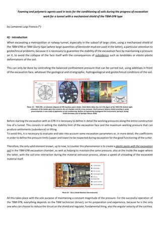
  • 4. D) - Why it is important to maintain the pressure inside the "excavation chamber" An excess of operating pressure can represent a destabilizing effect while, a pressure lower than the equilibrium limit, can cause the collapse of the face and cause surface subsidence (subsidence) of the ground following the excavation of tunnels, such as underground or underground tunnels underground mines. But I want to remind you that the effect of the pressure applied to the machine tends to reduce the effect of the extent of the subsidence (subsidence) because there is a continuous monitoring and control system inside the TBM-EPB. Photo 06 - Average composition for a normally used foam On the other hand, too high a pressure, excessively increases the stresses on the machine, decreases the forward speed and can in turn cause instability as it can generate the lifting of the ground above the excavation trajectory in correspondence with the construction of a superficial line tunnel underground. D.1) - APPLICABILITY OF THE EPB METHOD Therefore, for an EPB cutter to function optimally, the excavated material must have the following characteristics: - good plastic deformability; - low internal friction angle; - low permeability. In clayey-sandy and clayey-loamy soils, with a light consistency, the presence of this feature is optimal for the use of EPB type shields. However, it is difficult to find a material that is naturally only suitable for excavating in EPB mode, so steps are required to make the soil suitable for excavation: - the excavated materials are generally mixed with additives (chemical foams and polymers). Otherwise the fluid will not be able to have a uniform movement, and therefore can cause an arc effect and a porosity inside the diaphragm through which the water, usually present at the front, is able to flow freely, thus determining a possible collapse of the front itself. Therefore it is necessary to ensure a plastic excavation terrain, and this is made possible by using chemical agents (foams, stabilizers, anti-aggregating agents), this operation is called conditioning of the soil which is the test and the object of this report. Conditioning agents are usually injected from the shield, into the excavation chamber and into the cochlea. Therefore, the correct behavior of the foaming agent must be evaluated in advance on the basis of two performance indicators: the foaming and stability of the foam, which are quantified by the FER (Foam Expansion Ratio) and by the "half-life" period, the time required for the foam to drain 50% of the generator liquid used (EFNARC, 2005). Based on the minimum FER required, a concentration (Cf = 1.5 - 5%) of the foaming agent is recommended to develop adequate conditioning of the soil with a consumption between 0.5 - 2 Kg / m3. CHEMSPERSE - CHEMSURF-A-22 - CHEMSURF-H-38 - CHEMCRYL ADDITIVE 2 ADDITIVE 1 WATER SOLUTION AIR FOAM INJECTED AVERAGE COMPOSITION FOR A NORMALLY USED FOAM: - CHEMSURF-A-22 AND CHEMSURF-H-38 : 0.5 – 1 % -- WATER: 5 – 10 % -- AIR: 90 -95 % -- CHEMCRYL (EVENTUAL): < 0.1 % FOAMING AGENT CAN HAVE INSIDE A SMALL AMOUNT OF POLYMER TO STABILIZE THE FOAM BUBBLES FER FIR
  • 5. To further develop the soil conditioning scheme, further tests, such as Slump Tests and Hydraulic Permeability, must be conducted to evaluate the homogeneity, abrasiveness, workability and hydraulic permeability of the conditioned soil. On the basis of these further indicators, related to performance, a FIR (Foam Injection Ratio) injection ratio of the foaming agent is determined which usually, the latter indicator, is indicated by the TBM-EPB conductors between 30% and 60 %. Below, I want to briefly indicate how you get there you have FER and FIR values, of the two main properties of the foam, according to EFNARC 2005, which are: - FER: is the expansion ratio of the foam is the ratio between the volume of the foam at the operating pressure and the volume of the foam solution. FER = V foam / V foam solution The expansion ratio of the foam should be between 5-30. If the FER value is high; the foam generated must be drier. Drier foam should be used in moist soil and vice versa. - FIR: the foam injection ratio is the ratio between the volume of the foam at the operating pressure and the volume of the soil in situ to be excavated. FIR = 100 x V foam / V soil The foam injection ratio should be between 20-80% but in most cases it is between 30-60%. - However, in order to have information on the best FIR value, laboratory tests should be carried out; - while, I would like to point out that the water content of the soil and the water content of the injection are important. In fact, the type of foam is determined by the type of excavation soil encountered during the excavation phase. Therefore foams must be classified into three types; A, B and C (EFNARC, 2005): FOAM TYPE A: - The dispersion capacity is high (breaking of clay bonds) - Good coating ability (reduces swelling effects) FOAM TYPE B: - For general use - Medium stability FOAM TYPE C: - High stability - Anti-segregation properties (develop and keep the impermeable ground cohesive) However, to ensure the effectiveness of the soil conditioning schemes, which are based on the foaming agents used, it is important to verify with in situ tests and observations (including slump tests and visual inspections), samples of conditioned soil, collected on site, for satisfy all the necessary geological and geotechnical conditions. E) - Example of use of surfactants and a polymer
  • 6. To enter into the merits of the tests, the following products were used: a foaming agent formulated with particular anionic, biodegradable surfactants called CHEM-SURF-H-38; a liquid dispersing agent formulated with particular polycarboxylates called CHEM-SPERSE; and a synthetic liquid polymer, formulated with special acrylamide / sodium acrylate copolymers called CHEM- CRYL to be used separately or in combination. Tab. 01 – Foam classification and application area (EFNARC, 2005) The products that I take the liberty of suggesting and that can be used for ground conditioning, are those developed by the company CHEMIX s.r.l., of Golasecca (Varese), an Italian chemical industry, in collaboration with myself. Products designed with the aim of finding the right proportion to stabilize any type of soil under consideration. This solution, that of the two CHEM-SURF-H-38 + CHEM-CRYL or CHEM-SPERSE + CHEM-CRYL products, called FOAM agents, is the injection solution to be done at the excavation face, in the excavation chamber and in the auger. It can vary, depending on the ground conditions, even equal to 50% of the excavated volume. However, the proof of use of the FOAM was based on three fundamental operations: - the development of the percentages of product to create asoil treated to make it become quite fluid as mud (water-surfactant- polymer); - identify the pressure to be exerted on the mud to stabilize the excavation face; - identify the pressure to be applied on the ground that has become mud to control the excavation by operating both on the auger and on the thrust cylinders (in our case only one thrust cylinder is sufficient) to maintain balanced weights and volumes. In general, the products used during the soil treatment tests produced the following effects: - the Foams (type CHEM-SURF-H-38 and CHEM-SPERSE): they have maintained the stability of the face, with an increased capacity for plastic deformation of the ground (foam that is transformed into a homogeneous mousse), as well as a reduction in internal friction and the torque of the cutting head. - the Polymer (type CHEM-CRYL): it has maintained the stabilization of the soil and of the foams themselves, and water retention (ideal to be used even in the presence of large quantities of water).
  • 7. Finally, type CHEM-SPERSE has proved to be of interest as a ready-to-use product, and finds and can be used as: Photo 07 – Slump test - On the basis of numerous experiences developed in the laboratory with the execution of specific research aimed at defining of a "test protocol" of the "the conditioned medium" and on the basis of indications of "technical standards", in this study the "indicator, the drop test” to the Abrams cone (Slump Test) for the purpose of preliminarily characterize the “conditioned medium”. In test the following technical aspects were analyzed: - presence of a condition of the soil plasticity (qualitative observation); - falling to the cone of about 15-20cm; - reduced release of ”Water + Foam" from the mass of "the conditioned medium" after the test. - Dispersing agent: that is, to disperse / break up the strongly cohesive tabular structure of well-consolidated clayey soils, with a consequent decrease in their viscosity. Furthermore, this agent facilitates the resumption of excavation following stops or prolonged interruptions. I would like to underline that the choice of the specific product or combination of products, the identification of the various application parameters in relation to the product (concentration of the additive in the aqueous solution, rate of expansion of the foam, rate of injection into the soil) and the method of advancement to be followed depends, as already mentioned, on the geo-mechanical characteristics of the ground crossed during the excavation. Photo 08 - Graphic scheme - Conditioning layout showing injection at cutter face, working chamber and screw conveyor E.1) - TECHNICAL CHARACTERISTICS OF THE PRODUCTS USED DURING THE TEST E.1.1) - CHEM-SURF-H-38 - Density 1.04  0.02 kg / l - pH (for 1% solution) 7 - Total water solubility YES NO NO OPTIMAL CONDITIONING NOT ACCEPTABLE CONDITIONING, TOO FLUID NOT ACCEPTABLE CONDITIONING, TOO DRY All photos illustred are copied from the WEB FIR FER
  • 8. The dosage of the product diluted in water varies from 0.5 to 2% by weight. E.1.2) - CHEM-SPERSE - Density 1.26  0.02 kg / l - pH 7.5  0.2 - viscosity 300. 50 mPas - Total water solubility The product is formulated to be ready for use and ranges from 0.05 to 1.5% of the volume of the excavated soil. E.1.3) - CHEM-CRIL - Density 1.05  0.02 kg / l - pH (for a 5% solution) 6 - 8 - viscosity 1.000  400 cPs Its dosage varies from 2 to 4 kg per 1,000 liters of water (the product must be added to the water under constant stirring 20-30 minutes before the introduction of the foaming agent). Photo 09 - Spray test on the cutter head of foaming agent formulated with particular biodegradable anionic surfactants, S.E.L.I. Rome, Italy F) - Conclusion The tests carried out on site, with the use of FOAM, had the purpose of letting us know which parameters are necessary between weight and volumes of earth excavated and removed to guarantee the non-occurrence of collapses or superficial subsidence (subsidence) to obtain the characteristics of impermeability and plasticity, which are strictly correlated to the porosity of the soil used during the excavation phase. In general, by carrying out various tests, and finding ourselves in the presence of different types of soil, we have seen that the theoretical average quantity of FOAM that must be injected is equal to 300 l / m3. Furthermore, we verified whether the effect deriving from the compressibility of the foam (FOAM) reduces the pressure fluctuations on the excavation face, a test that was positive and necessary for the operators to have total control of the TBM-EPB. Finally, we also saw and evaluated that the foam not only allowed us to increase the workability of the excavated material and to reduce its permeability, because it was more fluid, but what is more interesting it prevents the adhesion of the soil-foam on the metal parts of the internal walls of the excavation chamber and auger eliminating the risk of obstructions. And to finish, we verified that the use of products, such as those mentioned above, allowed us to create a stable foam over time due to the foaming power of their composition and molecular structure. Therefore, I would like to point out that the comments reported in this report refer to real tests carried out directly on a construction site of a tunnel and not comments on tests carried out in the laboratory, which are usually made on samples of reduced material, with the result of having indicative data and it becomes necessary, during the excavation phase, to be verified directly on the TBM-EPB. All photos illustred are copied from the WEB
  • 9. (*) Luigi Franco, LAMANNA Independent Technical Consultant in the sector of Tunneling, Mining and Underground Technology Presidente of the Fondazione Internazionale di Centro Studi e Ricerche, ONG 132, via dei Serpenti, 00184 ROMA, Italia, U.E. E-mail: lamannaluigifranco1@gmail.com LinkedIn: Lamanna Luigi Franco DISCLAIMER This PDF is an amateur product which can not be applied Article. 5 of the Italian Law No 8 February 1948 n. 47, since the updating of the information contained in it has no regular periodicity (art. 1 paragraph 3, of the law 7 March 2001 n. 62). This PDF is not representing a journalistic head or whatever and posts published are intended to stimulate discussion and the technical study, criticism and freedom of expression of thought, in the manner and within the terms permitted by current Italian legislation. How known all over the world the material published on the Internet is public domain. Nevertheless, if someone would recognize their own material with Copyright and did not want to see it published on this PDF, it only has to give notice to the manager and will be immediately eliminated. We declare, moreover, they are not responsible for the comments included in the post. Any reader comments, damaging the image or repute of third persons, are not to be attributed to us, not even if these are expressed in an anonymous or encrypted.