1. CMP-3310 Software Engineering - Handouts
1 | P a g e
Chapter No 2
Software Process Models - 1
1. Software Development:
Software engineering is nothing but a disciplined approach to develop software.
Now we will look at some of the activities involved in the course of software
development. The activities involved in software development can broadly be
divided into two major categories first is construction and second is management.
The construction activities are those that are directly related to the construction or
development of the software. While the management activities are those that
complement the process of construction in order to perform construction
activities smoothly and effectively. A greater detail of the activities involved in the
construction and management categories is presented below.
1.1 Construction:
The construction activities are those that directly related to the development of
software, e.g. gathering the requirements of the software, develop design,
implement and test the software etc. Some of the major construction activities are
listed below.
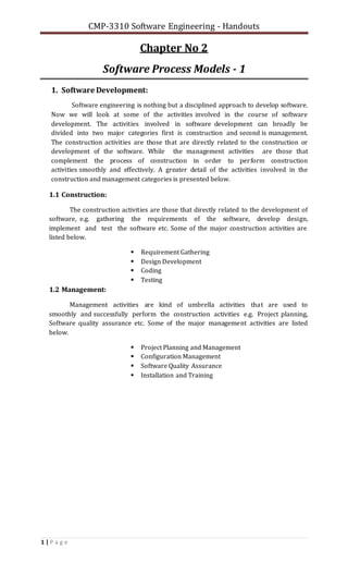
Requirement Gathering
Design Development
Coding
Testing
1.2 Management:
Management activities are kind of umbrella activities that are used to
smoothly and successfully perform the construction activities e.g. Project planning,
Software quality assurance etc. Some of the major management activities are listed
below.
Project Planning and Management
Configuration Management
Software Quality Assurance
Installation and Training
2. CMP-3310 Software Engineering - Handouts
2 | P a g e
Fig. 1: Software Development Activities
2. System Development Life Cycle:
The traditional methodology used in an organization to develop, maintain and
replace the software systems. Each methodology has its own SDLC.
Criteria for the Selection of Process Model to Develop a Project:
All process models have few common frameworks activities (Pressman 2005). The
problem is to select the most suitable model to be used for a particular project. These
are the criteria on the basis of which Project Manager selects the appropriate model for
a particular project.
Customer: Customer sometimes imposes the software house to follow a specific
model for his project.
Team Size: Team size is very critical factor that forces the software house to select a
specific model that suits to their team available for the project to be developed.
Technology: Technology in terms of development tool, platform and technical
capabilities to develop the project is also an important factor for the selection of
process model.
Reuse of the Existing Components: Object Oriented or Component-Based
Development process model helps to reuse the existing components.
Characteristics of the System: The main characteristics of a project also help a
project manager to select the best suitable process model for the current project.
i. Linear Sequential model is the best choice for a new project having
functionality similar to the previously completed projects.
ii. Rapid Application Development model is the appropriate choice for a
project having very tight deadlines.
iii. Evolutionary model are the best choice for a project having impossible
deadlines.
Justification of the Above Mentioned Criteria: The advantages and disadvantages of the
main process models are discussed in upcoming articles to justify the above mentioned
criteria.
3. CMP-3310 Software Engineering - Handouts
3 | P a g e
3. Software Processes:
A software process is a road map that helps you create a timely, high quality
result. It is the way we produce software and it provides stability and control. Each
process defines certain deliverables known as the work products. These include
programs, documents, and data produced as a consequence of the software engineering
activities.
A lifecycle model is a series of steps through which the product progresses.
These include requirements phase, specification phase, design phase,
implementation phase, integration phase, maintenance phase, and retirement.
Software Development Lifecycle Models depict the way you organize your activities.
There are a number of Software Development Lifecycle Models, each having its
strengths and weaknesses and suitable in different situations and project types.
The list of models includes the following:
Build-and-Fix Model
Waterfall Model
CBD Process Model
Rapid Prototyping Model
Rapid Application Development Model
Spiral Model
Rational Unified Process Model
4. Build-and-Fix Model:
It is unfortunate that many products are developed using what is known as the
build-and-fix model. In this model the product is constructed without specification or
any attempt at design. The developers simply build a product that is reworked as
many times as necessary to satisfy the client. This model may work for small
projects but is totally unsatisfactory for products of any reasonable size. The cost of
build-and fix is actually far greater than the cost of properly specified and carefully
designed product. Maintenance of the product can be extremely in the absence of any
documentation. It is depicted in Fig. 2.
In the build and fix model (also referred to as an ad hoc model), the software is
developed without any specification or design. An initial product is built, which is then
repeatedly modified until it (software) satisfies the user. That is, the software is
developed and delivered to the user. The user checks whether the desired functions 'are
present. If not, then the software is changed according to the needs by adding,
modifying or deleting functions. This process goes on until the user feels that the
software can be used productively. However, the lack of design requirements and
repeated modifications result in loss of acceptability of software. Thus, software
engineers are strongly discouraged from using this development approach.
This model includes the following two phases.
Build: In this phase, the software code is developed and passed on to the next
phase.
Fix: In this phase, the code developed in the build phase is made error free. Also, in
addition to the corrections to the code, the code is modified according to the user's
requirements.
4. CMP-3310 Software Engineering - Handouts
4 | P a g e
Fig. 2: Build-and-Fix Model
Advantages:
Requires less experience to execute or manage other than the ability to
program
Suitable for smaller software
Requires less project planning
Disadvantages:
No real means is available of assessing the progress, quality, and risks
Cost of using this process model is high as it requires rework until user's
requirements are accomplished
Informal design of the software as it involves unplanned procedure
Maintenance of these models is problematic
5. Waterfall Model:
The first published model of the software development process was
derived from other engineering processes. Because of the cascade from one phase
to another, this model is known as the waterfall model. This model is also known as
linear sequential model. This model is depicted in the following diagram.
The principal stages of the model map directly onto fundamental development
activities. It suggests a systematic, sequential approach to software development
that begins at the system level and progresses through the analysis, design,
coding, testing, and maintenance. In the literature, people have identified from 5 to 8
stages of software development. The five stages of waterfall model are as follows:
Requirement Analysis and Definition: Its focus is on What. The systems services,
constraints and goals are established by consultation with system users. They are then
defined in detail and serve as a system specification.
System and Software Design: Its focus is on How. The system design process
partitions the requirements to either hardware of software systems. It establishes
and overall system architecture. Software design involves fundamental system
abstractions and their relationships.
Implementation and Unit Testing: Its main focus is on How. During this stage the
software design is realized as a set of programs or program units. Unit testing involves
verifying that each unit meets its specifications.
5. CMP-3310 Software Engineering - Handouts
5 | P a g e
Integration and System Testing: The individual program unit or programs are
integrated and tested as a complete system to ensure that the software
requirements have been met. After testing, the software system is delivered to the
customer.
Operation and Maintenance: Normally this is the longest phase of the software life
cycle. The system is installed and put into practical use. Maintenance involves
correcting errors which were not discovered in earlier stages of the life-cycle,
improving the implementation of system units and enhancing the system’s services
as new requirements are discovered.
Fig. 3: Waterfall Model
In principle, the result of each phase is one or more documents which are
approved. No phase is complete until the documentation for that phase has been
completed and products of that phase have been approved. The following phase should
not start until the previous phase has finished.
Real projects rarely follow the sequential flow that the model proposes. In
general these phases overlap and feed information to each other. Hence there should be
an element of iteration and feedback. A mistake caught any stage should be referred
back to the source and all the subsequent stages need to be revisited and corresponding
documents should be updated accordingly. This feedback path is shown in Fig. 4.
Because of the costs of producing and approving documents, iterations are
costly and require significant rework. The Waterfall Model is a documentation-driven
model. It therefore generates complete and comprehensive documentation and hence
makes the maintenance task much easier. It however suffers from the fact that the
client feedback is received when the product is finally delivered and hence any
errors in the requirement specification are not discovered until the product is sent to
the client after completion. This therefore has major time and cost related
consequences.
6. CMP-3310 Software Engineering - Handouts
6 | P a g e
Fig. 4: Feedback Path in Waterfall Model
Advantages:
A complete comprehensive understanding regarding system development
Suitable for research projects
Disadvantages:
Not feasible for real life commercial projects because of phase organization
More time is required to develop a software
Working version of the software is available late in the project at the start of
the sixth phase during implementation phase. This can result in a total
disaster if the customer requirements are vague
It is not practically possible to collect complete requirements initially at the
start of the project that is fundamental requirement of this model
6. CBD Model:
The CBSE process is used to:
o Identify desirable components;
o Qualify each component’s interface;
o Adapt components to remove architectural mismatches;
o Assembles components into a selected architectural style;
o Update components as requirements changes.
The process model for CBSE emphasizes parallel tracks in which domain
engineering occurs concurrently with CBD.
The main phases of CBD process model are as follows.
a. Communication
b. Planning
c. Analysis, component selection and Risk Management
d. Engineering and testing
e. Evaluation
The customer is communicated at the start of the project to gather basic
requirements. Initial use cases are developed at this stage.
7. CMP-3310 Software Engineering - Handouts
7 | P a g e
Project specification or proposal document is prepared during the planning phase.
Project specification or proposal document is composed of feasibility and risk
assessments that are performed to prepare a cost benefits analysis (CBA) sheet.
Fig. 5: CBD Process Model
CBA sheet helps to estimate that whether the SW project is feasible for the customer
or not.
Analysis phase is only started if the customer approves the proposal.
Risk Analysis, Component Selection and Risk Management phase- It is the phase
where an analyst gathers detailed requirements and tries to identify and select
those components that can be reused from the components repository.
Risks regarding the use of existing components are evaluated and managed. The
relationships among components are identified.
The properties and behaviors of the components are identified as well.
Core objective of this phase is to reuse maximum components, rather than
reinventing the wheel.
It will also improve productivity and efficiency of software engineers.
Engineering and testing phase- the selected components are modified (customized)
according to the requirements of new system to be developed and tested.
The new components are designed, developed and tested on unit basis.
Integration and system tests of the newly developed and of the reused components
are performed.
Evaluation phase- Customer is requested to evaluate and verify SW that whether it
meets his/her requirements or not.
8. CMP-3310 Software Engineering - Handouts
8 | P a g e
7. Rapid Prototyping Model:
A cyclic diagram can show the phases of the rapid prototyping model.
Fig. 6: Rapid Prototyping Process Model
This model has three main phases.
Listen (to the customer)
Develop A Demo Version of Software
Evaluate (by the customer)
The customer is called at the Software Engineer/Developer`s site or he/she visited
to customer in order to gather the main requirements of the software. The software
engineer developed a demo version of the software and called the customer at his/her site
to evaluate the demo. The customer and software engineer sits together. The customer
feed-back about the demo is again listened by the developer. The developer rebuilds the
demo according to the changes and new requirements inquired by the customer. The
customer is again called to re-evaluate the demo and this process continues until the final
version of the customer satisfaction. Prototype model provides no documentation for the
software as in the case of waterfall model. There are two main types of prototype model
known as Throwaway and Evolutionary Prototype.
The developer throws the demo software after every evaluation by the customer and
develops the new demo version or evaluation in Throwaway Prototype. The evolutionary
approach is used to develop the first demo and make further changes or maintenance in it
until the customer approved the final version of demo software.
Advantages:
Best suitable to integrate with other methodologies such as waterfall to make
them more effective
Faster development results in dramatic time and cost saving
Disadvantages:
No proper documentation to be used for current and future projects
Faster development often results in poor quality software
Never used alone to develop software
9. CMP-3310 Software Engineering - Handouts
9 | P a g e
Relies heavily on end user in terms of functionalities and interfaces can result
in a less efficient software. End users sometimes do not want to make the
software project successful having the threat of job risk or due to their
easiness in terms of software usage causing the removal of some key features
or functions of the software that may be hard to use. Is it possible that CEO of
any organization can have so much time to evaluate the software again and
again? No, therefore he will send the end user; who can become a source of
software project failure in terms of software implementation.
8. Rapid ApplicationDevelopment (RAD) Model:
The main phases of RAD model are as follows.
Requirements & Planning
User Design
Development
Cutover
Fig. 6: Rapid Application Development Process Model
As the figure indicates that RAD model is compressed, modified and improved
version of the actual waterfall model. The project identification & selection, project
initiation & planning and analysis phase of the waterfall model have been merged into first
phase of the RAD model called Requirements & Planning, It means the feasibility
assessments and gathering requirements are done in parallel. The logical design and
physical design are being merged in the User Design phase. The prototype model is heavily
used during the user design and development phases to finalize the interfaces and verify
the requirements in terms of functionalities. This can be seen by a back arrow indicated
from the development to design phase. The cutover phase indicates the maintenance and
testing of the software.
10. CMP-3310 Software Engineering - Handouts
10 | P a g e
Fig. 7: Waterfall Model – Another Phase List
Advantages:
Best suitable for real life small scale commercial projects
Faster development results in time and cost saving
More complete user requirements because of use of prototype approach
Focuses on the main features of the software from the user`s point of view
Cover all phases of the waterfall model, but at a rapid rate
Disadvantages:
Faster development results in poor quality software
Use of the prototype approach incorporates all its disadvantages into RAD
model
Not suitable for safety critical projects where life risks are involved
9. Spiral/Evolutionary/Incremental Model:
The main phases of Evolutionary model are as follows.
Communication with the customer
Planning
Risk Analysis
Engineering
Testing
Customer Evaluation
Customer is communicated during the first phase to gather the basis
specification of the software project. The planning phase is composed of developing
a feasibility report in terms of schedule, economic, technical and operation
11. CMP-3310 Software Engineering - Handouts
11 | P a g e
feasibilities. The schedule feasibility reflects the start and finishing duration of each
phase. Microsoft Project or Microsoft Excel is used to draw Gantt Charts. The
economic feasibility has the monetary figures indicating that how much a project is
feasible and the benefits can be gained by using the project. The technical feasibility
show that the desired hardware and software are available for development of that
project and how much are the costs. The operational feasibility has the measures
that how much operational costs are required and what will be the operational
benefits.
The approvals of this phase by the customer pass the developers to move to the
risk analysis phase. The developer of the project gathers the detailed requirements
and calculates all the potential risks involved. The engineering phase has three main
activities. The logical design, physical design and coding of the project. The
developer tests the project for debugging in testing phase. There are two main
approaches available for testing of any software. The software application is tested
and evaluated by the customer during customer evaluation phase. The first round of
spiral may just help us to complete the project specification of the project. During
the next cycle we may develop the first part or module of the software that is
normally core part of the software. After its evaluation and approval by the
customer it is delivered to customer for usage. For example, in Microsoft Word,
writing area is the core part. If the customer approved the core part then we start
working on other parts. For example, spell checker, formatting and drawing
modules. The evolutionary process can be used for the entire life of the software to
add new parts. Unlike waterfall model that can be used only to work on the software
as a whole. The planning, analysis, engineering, testing and customer evaluation is
done for each new part. The increments are continuously added according to the
requirements of customer and this evolutionary process continues up to entire life
of the software. Spiral model is depicted in the following figure.
Fig. 8: Spiral Model
Advantages:
Using this approach, more complete software could be developed
Best suitable for modular development
12. CMP-3310 Software Engineering - Handouts
12 | P a g e
Best suitable if you have less number of developers. You can hire more staff if
your core has been accepted
Best suitable for web projects because web applications are continuously
evolving according to the business or customer needs
Disadvantages:
Not suitable for developing artificial intelligence and neural networks
software where more detailed activities are required during each phase of
the SDLC and modified waterfall model is used
10. Rational Unified Process Model:
The Rational Unified Process (RUP) is an example of a modern process model
that has been derived from work on the UML and the associated Unified Software
Development Process. It is a good example of hybrid process model that brings
together elements from all generic process models, iterations and illustrates good
practices of specification and design.
The RUP recognizes that conventional process models present a single view
of the process. In contrast, the RUP is normally described from three perspectives:
A dynamic perspective that shows the phases of the model over time
A static perspective that shows the process activities that are enacted
A practice perspective that suggests good practices to be used during
the process
The RUP is a phased model that identifies four discrete phases in the
software process. However, unlike the waterfall model where phases are equated
with process activities, the phases in the RUP are more closely related to business
rather than technical concerns. Fig. 9 shows the phases in the RUP.
Fig. 9: Rational Unified Process Model
Inception: The goal of the inception phase is to establish a business case for the system.
You should identify all external entities (people and systems) that will interact with the
system and define these interactions. You then use this information to assess the
contribution that the system makes to the business. If this contribution is minor, then the
project may be cancelled after this phase.
Elaboration: The goals of the elaboration phase are to develop an understanding of the
problem domain, establish an architectural framework for the system, develop the project
plan and identify key project risks. On completion of this phase. You should have a
13. CMP-3310 Software Engineering - Handouts
13 | P a g e
requirements model for the system (UML use cases are specified), an architectural
description and a development plan for the software.
Construction: The construction phase is essentially concerned with system design,
programming and testing. Parts of the system are developed in parallel and integrated
during this phase. On completion of this phase, you should have a working software system
and associated documentation that is ready for delivery to users.
Transition: The final phase of the RUP is concerned with moving the system from the
development community to the user community and making it work in a real environment.
This is something that is ignored in most software process models but is, in fact, an
expensive and sometimes problematic activity. On completion of this phase, you should
have a documented software system that is working correctly in its operational
environment.
Iteration within the RUP is supported in two ways as shown in Fig. 9. Each phase may be
enacted in an iterative way with the results developed incrementally. In addition, the whole
set of phases may also be enacted incrementally, as shown by the looping arrow from
Transition to Inception in Fig. 9.
End of Chapter 2