Marine Steering Gear and SOLAS Requirements
•
134 likes•38,916 views

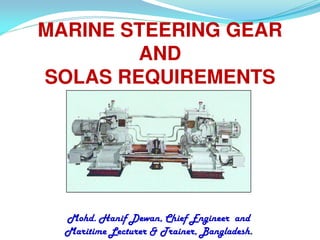
Marine Steering Gear and SOLAS Requirements by Mohd. Hanif Dewan, Chief Engineer and Maritime Lecturer & Trainer, Bangladesh.

Recommended
More Related Content
What's hot
What's hot (20)
Viewers also liked
Viewers also liked (20)
Similar to Marine Steering Gear and SOLAS Requirements
Similar to Marine Steering Gear and SOLAS Requirements (20)
More from Mohammud Hanif Dewan M.Phil.
More from Mohammud Hanif Dewan M.Phil. (20)
Recently uploaded
Recently uploaded (20)
Marine Steering Gear and SOLAS Requirements
- 1. MARINE STEERING GEAR AND SOLAS REQUIREMENTS Mohd. Hanif Dewan, Chief Engineer and Maritime Lecturer & Trainer, Bangladesh.
- 2. REGULATIONS AS PER 11/11/2014 Mohd. Hanif Dewan, Chief Engineer and Maritime Lecturer & Trainer, Bangladesh 2
- 3. SOLAS REGULATIONS 1. Chapter II-I : Construction, Subdivision, Stability, Machinery and Electrical Installation • Regulation 29 : Steering Gears • Regulation 30 : Additional Requirements for Electric and Electrohydraulic Steering Gears 2. Chapter V : Safety of Navigation • Regulation 19 : Use of Automatic Pilot • Regulation 19-1 : Operation of Steering Gears • Regulation 19-2 : Steering Gears – Testing and Drills 11/11/2014
- 4. CHAPTER II-I Requirements :- Regulation 29 : Steering Gears 1. Provision of Main and Auxiliary Steering Gears. Failure of one will not render the other inoperative Construction 2.1 All components and rudder stocks shall be of sound and reliable construction 2.2 Design pressure of piping scantlings and components at least 1.25 times of maximum working pressure. Fatigue criteria shall be applied for the design of pipings etc. 2.3 Setting of relief valve shall not exceed design pressure. 11/11/2014
- 5. SOLAS REGULATION 29 3 Main steering gear and rudder stock shall be: 3.1 of adequate strength and capable of steering the ship at maximum ahead speed 3.2 capable of putting the rudder over from 350 on one side to 350 on the other side at its deepest seagoing draught and running ahead at maximum ahead service speed and under same condition from 350 on either side to 300 on the other side in not more than 28 11s/11e/20c14 onds.
- 6. SOLAS REGULATION 29 4 The auxiliary steering gear shall be: 4.1 of adequate strength and capable of being brought speedily into action in an emergency 4.2 able to put the rudder over from 150 on one side to 150 on the other side in not more than 60 seconds at its deepest seagoing draughts and running ahead at one half of the maximum ahead service speed or 7 knots whichever is greater. 11/11/2014
- 7. SOLAS REGULATION 29 Power Requirement 5 Main and auxiliary steering gear power unit shall be: 5.1 arranged to restart automatically when power is restored after a power failure 5.2 provided audible and visual alarm when power failure to any one of the power units 6.1 Auxiliary steering gears need not be fitted: Main steering gear comprised TWO or more identical power units and provided that: 11/11/2014
- 8. SOLAS REGULATION 29 6.1.1 Passenger ships : Main steering gear is able to operate the rudder as in 3.2 while any one of the power unit is out of operation 6.1.2 Cargo ships: Main steering gear is able to operate the rudder as in 3.2 while operating with all power units 6.1.3 After a single failure in its piping system or in one of the power units, the defect can be isolated, so that steering capability can be maintained or speedily regained 11/11/2014
- 9. SOLAS REGULATION 29 7 Steering gear control shall be provided: 7.1 both on the navigational bridge (n.b) and in the steering gear compartment (s.g.c) 8 Main and auxiliary steering gear control system operable from the n.b shall: 8.1 if electric, served by its own separate circuit supplied from a steering gear power circuit within the s.g.c. or directly from the busbars 11/11/2014
- 10. SOLAS REGULATION 29 8.2 means provided in s.g.c. to disconnect any control system operable from the n.b. 8.3 system capable of being brought into operation from the n.b. 8.4 audible and visual alarm given on n.b when failure of power supply to control system 8.5 short circuit protection only for steering gear control supply circuit. 11/11/2014
- 11. SOLAS REGULATION 29 9 Separate as far as practicable, electrical power circuits, control systems with their components, cables and pipes . 10 Means of communication shall be provided between the n.b. and the s.g.c. 11 Angular position of rudder shall: 11.1 if power operated, be indicated on the n.b. Rudder angle indication shall be independent of the control system 11/11/2014
- 12. SOLAS REGULATION 29 11.2 rudder angle shall be recognizable in s.g.c. 12 Hydraulic power operated steering gear shall be provided with arrangement to / for: 12.1 maintain the cleanliness of the hydraulic fluid 12.2 low level alarm at each fluid reservoir to give earliest indication of fluid leakage.Audible and visual alarm given at n.b and E/R. 12.3 fixed storage tank, with content gauge, having sufficient capacity to recharge one power actuating system including the reservoir. 11/11/2014
- 13. SOLAS REGULATION 29 13 The steering gear compartment shall be: 13.1 readily accessible, and as far as practicable, separated from machinery space 13.2 provided with handrails and gratings or nonslip surfaces for working access to machinery and controls in event of hydraulic fluid leakages. 14 Where rudder stock is over 230mm in diameter,in way of tiller, alternative power supply provided automatically within 45 sec. and for ship 10,000 gt and upward, supply of at least 30 min of continuous operation while other ships 10 minutes. 11/11/2014
- 14. SOLAS REGULATION 29 15.Every tanker, chemical tanker or gas carrier of 10,000 gt and above and other ships of 70,000 gt and upward,main steering gear shall comprise two or more identical power units. 16.Every tanker, chemical tanker or gas carrier of 10,000 gt and above shall: 16.1 When loss of steering from single failure in any of the power actuating system, steering shall be regained in not more than 45 sec. 11 /11/2 014 cont’d
- 15. SOLAS REGULATION 29 16.2.2 interconnection of hydraulic power actuating systems shall be provided. Loss of hydraulic fluid shall be capable of being detected, and defective system automatically isolated so that the other actuating system remain fully operational. 17 Tanker, chemical tankers or gas carriers 10,000 gt to <100,000 dwt. may be exempted from single failure criteria, provided an equivalent standard is achieved. 11/11/2014
- 16. SOLAS REGULATION 29 18 Tanker, chemical tanker or gas carrier 10,000gt to <70,000 dwt., until 01 Sept. 1986, may be exempted from complying single failure criteria if it has a record of reliability. 19 Tanker, chemical tanker or gas carrier of 10.000 gt and more, constructed before 01 Sept. 1984, shall comply not later than 01 Sept. 1986 with para. 7.1, 8.2, 8.4, 10, 11, 12.2, 12.3, and 13.2 11/11/2014
- 17. SOLAS REGULATION 29 20. Tanker, chemical tanker or gas carrier of 40,000gt and more, arrangement for steering capability provided, if a single failure occurs. 11/11/2014
- 18. SOLAS REGULATION 30 1. Means of indicating the power units (motors) are running shall be installed at E/R & n.b. 2. Power units have two exclusive circuits, of adequate ratings, directly from main switch board/one of it from emergency switch board. 3. Short circuit protection, alarm for overload and failure of any one of the 3 phase supply, audible and visual, for the circuits and motors. 11/11/2014
- 19. SOLAS REGULATION 30 4. Ship less than 1,600 gt where auxiliary steering gear is powered by motor for other services, main steering gear may be supplied by one circuit from the main switch board. 11/11/2014
- 20. CHAPTER V SOLAS REGULATION 19 Use of automatic pilot (a) It shall also be possible for human control of the steering immediately, when using automatic pilot in heavy traffic, poor visibility & hazardous situation. (b) A qualified helmsman shall be ready at all time to take over steering control (c) Manual steering shall be tested after prolong use of automatic pilot and in situation demand so. 11/11/2014
- 21. CHAPTER V SOLAS REGULATION 19-1 Operation of steering gear Where navigation demands special caution, ships shall have more than one power units in operation where simultaneous operation is possible. 11/11/2014
- 22. CHAPTER V SOLAS REGULATION 19-2 Steering gear: Testing and Drills (a) Within 12 hours before departure, following shall be checked and tested, if applicable: • Main steering gear/auxiliary steering gear • Remote steering gear control systems • Steering positions on n.b. • Emergency power supply • Rudder angle indicators to actual rudder position • Remote steering gear control system power failure alarms. Cont’d 11/11/2014
- 23. CHAPTER V SOLAS REGULATION 19-2 • Steering gear power unit failure alarms • Automatic isolating arrangements and other automatic equipment The checks and tests shall include: • Full movement of the rudder • Visual inspection of the steering gear and linkages • Means of communication between steering gear compartment and n.b. Cont’’ d 11/11/2014
- 24. CHAPTER V SOLAS REGULATION 19-2 (c) Operating instruction with a block diagram is displayed on n.b and s.g.c. • Ship officer concerned with operation and maintenance of steering gear is familiar with the operation and changing over from one system to another. (d) Emergency steering drills shall take place at least once every three months. *Date of testing, checking and details of emergency steering drills shall be recorded in the log-book. 11/11/2014
- 25. TELEMOTOR TRANSMITTER & RECEIVER 11/11/2014 Mohd. Hanif Dewan, Chief Engineer and Maritime Lecturer & Trainer, Bangladesh 25 STEERING GEAR TELEMETRIC/TRANSDUCER/TELEMOTOR ACTUATING SYSTEM HYDRAULIC TELEMOTOR ELECTRIC TELEMOTOR TRANSMITTER RECEIVER ELECTRO HYDRAULIC ALL ELECTRIC RAM ROTARY VANE WARD SINGLE LEONARD MOTOR 2-RAM 4 -RAM
- 26. Telemoto r system 1. This consists of transmitter at n.b. and receiver unit at s.g.c. 2. The transmitter sends a signal for the change of direction of motion of ship 3. The receiver is an equipment that receive the signal and make the actuating system response 11/11/2014 Mohd. Hanif Dewan, Chief Engineer and Maritime Lecturer & Trainer, Bangladesh 26
- 27. Hydraulic transmitter • Consist of two rams ending in racks that mesh with a primary pinion attached to steering wheel shaft and housed in a casing. • The top houses the racks and pinion and serve as the replenishing tank. The racks and pinion being lubricated by this fluid. • Bottom half has two cylinders where the rams reciprocate, passing through sealing glands. Cont’d 11/11/2014 Mohd. Hanif Dewan, Chief Engineer and Maritime Lecturer & Trainer, Bangladesh 27
- 28. • When steering wheel is turned manually, it turns the primary pinion that moves the racks. • If the wheel is turned to starboard, the right hand rack moves downwards and the left hand one moves up • The movement of the rams causes the fluid from right hand cylinder to be pushed out to the receiver unit and an equal amount returns to the left cylinder . • A by-pass valve is fitted to accommodate variation of oil volume due to temperature changes, relief in case of pressure built-up and for equilibrium between two cylinders when wheel is at amidships or no working condition Cont’d 11/11/2014 Mohd. Hanif Dewan, Chief Engineer and Maritime Lecturer & Trainer, Bangladesh 28
- 29. 11/11/2014 Mohd. Hanif Dewan, Chief Engineer and Maritime Lecturer & Trainer, Bangladesh 29
- 30. 11/11/2014 Mohd. Hanif Dewan, Chief Engineer and Maritime Lecturer & Trainer, Bangladesh 30
- 32. 11/11/2014 Mohd. Hanif Dewan, Chief Engineer and Maritime Lecturer & Trainer, Bangladesh 32
- 33. By -Pass Valve Equalising Connection 11/11/2014 Mohd. Hanif Dewan, Chief Engineer and Maritime Lecturer & Trainer, Bangladesh 33
- 34. Telemotor Charging System 11/11/2014 Mohd. Hanif Dewan, Chief Engineer and Maritime Lecturer & Trainer, Bangladesh 34
- 35. Telemotor Hydraulic Fluid • Low pour point (-500C) • Low viscosity ( 30 Redwood sec. at 600C) • High viscosity index (110) • High flash point (closed flash point 1500C) • Non sludge forming • Non corrosive • Good lubricating properties 11/11/2014 Mohd. Hanif Dewan, Chief Engineer and Maritime Lecturer & Trainer, Bangladesh 35
- 36. Testing or Checks • If steering wheel is moved, it springs back to midships - receiver has compressed spring. • Wheel turned till receiver against stops - check wheel • Receiver hold stops for half hours - no oil leakages • Check rudder angles by turning wheel. Smooth movement means no air trapped in system. 11/11/2014 Mohd. Hanif Dewan, Chief Engineer and Maritime Lecturer & Trainer, Bangladesh 36
- 37. Electric Telemotor 11/11/2014 Mohd. Hanif Dewan, Chief Engineer and Maritime Lecturer & Trainer, Bangladesh 37
- 38. 11/11/2014 Mohd. Hanif Dewan, Chief Engineer and Maritime Lecturer & Trainer, Bangladesh 38
- 39. Automatic Steering System (Close loop system) 11/11/2014 Mohd. Hanif Dewan, Chief Engineer and Maritime Lecturer & Trainer, Bangladesh 39 Steering Wheel Controller Telemotor Transmitter Variable Displacement Pump Telemotor Receiver Steering Gear Actuator Compass Ship Rudder Actual course Set course Feedback
- 40. Common faults / causes - hydraulic telemotor 1. Fault: Wheel slack, no initial pressure. Excess movement before receiver moves. Cause: Air in system. 2. Fault: Receiver does not return to midship when transmitter at midship. Cause: By-pass valve not functioning. Broken receiver return spring. Seizure of hunting gear arrangement. 11/11/2014 Mohd. Hanif Dewan, Chief Engineer and Maritime Lecturer & Trainer, Bangladesh 40
- 41. Diagram of emergency steering - telemotor fails 11/11/2014 Mohd. Hanif Dewan, Chief Engineer and Maritime Lecturer & Trainer, Bangladesh 41
- 42. Actuating System is divided into: 1. Power or amplifying unit (a) Electrical units (b) Hydraulic pumps 2. Actuating mechanism (a) Electrically operated (b) Hydraulically operated 11/11/2014 Mohd. Hanif Dewan, Chief Engineer and Maritime Lecturer & Trainer, Bangladesh 42
- 43. Power Units - Hydraulic Pumps • Pumps have to be of positive displacement type • Able to pump the hydraulic fluid in all conditions • Commonly used are the reciprocating - rotary variable delivery pumps (a) Hele Shaw / Radial Piston Pump (b) Swash Plate / Axial Piston Pump 11/11/2014 Mohd. Hanif Dewan, Chief Engineer and Maritime Lecturer & Trainer, Bangladesh 43
- 44. Introduction A variable delivery pump is generally used in applications, which require constant variation in the amount of oil that is to be supplied. The principle behind any type of variable displacement pump is to alter the pump stroke in order to vary the amount of oil displaced, according to the requirement. Two main parts of the variable delivery pump are - floating ring , swash plate or a slippery pad. Construction The variable pump assembly,also known as radial cylinder Hele Shaw pump, consists of a short shaft, which is attached to a cylindrical body that rotates inside the casing. The cylindrical body surrounds a central valve and has ball bearings at the ends. The central valve and the cylindrical ports are connected to each other by means of ports, which open in the outer casing from where the oil is supplied and delivered. All the cylinder bodies have pistons inside and are fastened to the slippers by means of gudgeon pin. All these slippers are located inside slots made in the circular floating ring, which can also rotate in any directions because of the bearings mounted in the guide blocks. Two spindles control the movement of the ring and comes out of the casing though the slots provided. 11/11/2014 Mohd. Hanif Dewan, Chief Engineer and Maritime Lecturer & Trainer, Bangladesh 44
- 45. 11/11/2014 Mohd. Hanif Dewan, Chief Engineer and Maritime Lecturer & Trainer, Bangladesh 45
- 46. Working Procedure: No Flow Condition As shown in the FIG (a), the circular ring, which accommodates the slippers is concentric with the central valve arrangement. Due to this, the piston doesn't have any relative reciprocating motion inside the cylinder. No oil is pumped or sucked in and although the pump is rotating no fluid is delivered, during this state. 11/11/2014 Mohd. Hanif Dewan, Chief Engineer and Maritime Lecturer & Trainer, Bangladesh 46
- 47. Oil Flow Condition - When the circular floating ring is pulled to the right FIG (b), the pistons in the cylinder undergo a reciprocating motion. - The lower piston moves inwards and discharges fluid through the lower port. - The piston moves till the horizontal position and then moves outwards in the opposite direction, drawing in fluid through the upper ports. Thus in this way the top ports act as suction ports and the lower ports act as discharge ports. - If the circular ring is pushed to the left direction FIG (c), the suction and discharge ports are reversed i.e. the lower ports act as suction ports and the top ports act as discharge ports. Locking Arrangement: All the variable displacement pumps are positive displacement pumps, with a constantly rotating arrangement and a variable discharge design. If the system has more than one pump, a non reversing locking gear is provided, which prevents the reverse operation that might take place at times when only one pump is operating. Moreover, the arrangement is such that as soon as the pump is stopped the locking gear would come into action . 11/11/2014 Mohd. Hanif Dewan, Chief Engineer and Maritime Lecturer & Trainer, Bangladesh 47
- 48. Hele Shaw Pump - Operating Principle 11/11/2014 Mohd. Hanif Dewan, Chief Engineer and Maritime Lecturer & Trainer, Bangladesh 48
- 49. Axial Piston Pump- Swash Plate Pump • Constant speed motor rotates shaft, cylinder barrel and socket ring. • No Pumping action when swash plate, socket ring at zero position. • Tilted swash plate causes socket ring to revolve at an angle to cylinder barrel - pumping action. • The plungers then slide in the cylinder from maximum to minimum in one half revolution. 11/11/2014 Mohd. Hanif Dewan, Chief Engineer and Maritime Lecturer & Trainer, Bangladesh 49
- 50. Working Procedure of a Swash Plate Pump: - Swash plate pumps have a rotating cylinder containing pistons. - A spring pushes the pistons against a stationary swash plate, which sits at an angle to the cylinder. - The pistons suck in fluid during half a revolution and push fluid out during the other half. - Shown on edge on the far right in the figure is a stationary disk. It contains two semi-circular ports. - These ports allow the pistons to draw in fluid as they move toward the swash plate (on the backside) and discharge it as they move away. - For a given speed swash plate pumps can be of fixed displacement or variable by having a variable swash plate angle. The greater the swash plate angle the further the pistons move and the more fluid they transfer. 11/11/2014 Mohd. Hanif Dewan, Chief Engineer and Maritime Lecturer & Trainer, Bangladesh 50
- 51. Swash plate pump 11/11/2014 Mohd. Hanif Dewan, Chief Engineer and Maritime Lecturer & Trainer, Bangladesh 51
- 52. Swash Plate Pump Video 11/11/2014 Mohd. Hanif Dewan, Chief Engineer and Maritime Lecturer & Trainer, Bangladesh 52
- 53. 11/11/2014 Mohd. Hanif Dewan, Chief Engineer and Maritime Lecturer & Trainer, Bangladesh 53
- 54. Advantages of Axial Piston Pumps 1. Torque characteristics better. 2. Response is better. 3. Do not overheat (casing full with oil at neutral) Disadvantages of Radial Piston Pump 1. Bigger in size 2. Torque transmission and response slower 3. Overheat- casing not filled with oil at neutral. 11/11/2014 Mohd. Hanif Dewan, Chief Engineer and Maritime Lecturer & Trainer, Bangladesh 54
- 55. Hydraulic motoring in Axial Piston Pump Running Pump Pump Discharge 11/11/2014 Mohd. Hanif Dewan, Chief Engineer and Maritime Lecturer & Trainer, Bangladesh 55 Stand–by pump To Rams From Rams Both swash plates tilted same direction Undesirable: 1. Part of pump output driving idle pump 2. Slow response of steering gear system 3. Churning & heating of hydraulic fluid F Fcos Fcos causes a turningF sin moment
- 56. TO AVOID HYDRAULIC MOTORING 1. Ratchet and pawl mechanism in coupling between pump and motor Under motoring condition, when pump at rest, pawls engage onto ratchet Cont’d 11/11/2014 Mohd. Hanif Dewan, Chief Engineer and Maritime Lecturer & Trainer, Bangladesh 56 Pawl mounted on coupling Ratchet is stationary secured to motor supporting structure When pump is working, pawls fly outwards due to centrifugal force
- 57. 2.Servo-operated automatic change over valve (By-pass condition) Pipes to & from its own Pressure from its own pump auxiliary pump Constant pressure from aux. Pump of other unit Operating on reduced area Spring Bleed to prevent hydraulic locking Pipes to & from actuating mechanism or main hydraulic system
- 58. Hunting Gears arrangement Tiller arm 11/11/2014 Mohd. Hanif Dewan, Chief Engineer and Maritime Lecturer & Trainer, Bangladesh 58 Motor Pump Pump actuating/stroke control lever Hunting gear floating lever Buffer spring and link Rudder stock Telemotor receiver Emergency hand control
- 59. Hunting Gear 11/11/2014 Mohd. Hanif Dewan, Chief Engineer and Maritime Lecturer & Trainer, Bangladesh 59
- 60. Hunting Gear • The steering gear system above consists of the telemotor which receives a signal from the bridge wheel. This acts on the hunting gear. • The hunting gear moves displacing a control rod, this rod acts on the pump displacement control gear to alter the delivery from the pump. The delivery from the pump causes the ram to move rotating the rudder stock and hence the rudder. The other end of the hunting gear is mounted on the rudder stock. 11/11/2014 Mohd. Hanif Dewan, Chief Engineer and Maritime Lecturer & Trainer, Bangladesh 60
- 61. The rotation of the rudder stock moves the hunting gear returning the operating rod for the pump to the neutral position once the rudder has reached the correct angle. 11/11/2014 Mohd. Hanif Dewan, Chief Engineer and Maritime Lecturer & Trainer, Bangladesh 61
- 62. 11/11/2014 Mohd. Hanif Dewan, Chief Engineer and Maritime Lecturer & Trainer, Bangladesh 62
- 63. Hunting Gear Operation Principle 11/11/2014 Mohd. Hanif Dewan, Chief Engineer and Maritime Lecturer & Trainer, Bangladesh 63 R P T R’ P’ T R’ P T ’ R P’’ T’ R (Receiver) P (Pump) T (Tiller) 1. 2. 3. 4. 5. 1. Wheel midships: R - midships, P - zero, T- zero. 2. Wheel to starboard: R to R’, P to P’ pivot about T. ( Pump starts, pushes ram to left , turns rudder to starboard) 3. Rudder turns, tiller feed back pushes T to T’, pump control zero, pumping stops, rudder stop at starboard. Explain 4 and 5!
- 64. Buffer spring (hunting gear arrangement) 1. Take up any excess movement beyond the maximum stroke of the pump, such as, maladjustment of hunting gear arrangement. (extra movement is stored by spring and used to reset itself as hunting gear reaches no effect point) 2. Takes up the effect (shock loading) of heavy seas, e.g. waves on the rudder. 11/11/2014 Mohd. Hanif Dewan, Chief Engineer and Maritime Lecturer & Trainer, Bangladesh 64
- 65. Purpose of Hunting Gear: 1. Hunting gear floating lever mechanism is required to bring the rudder to the ordered position. 2. It maintain the steering gear pumping operation. 3. Also this mechanism is required to position the rudder in its ordered position when the action of water, waves or propeller force displaces the rudder from its ordered position. 11/11/2014 Mohd. Hanif Dewan, Chief Engineer and Maritime Lecturer & Trainer, Bangladesh 65
- 66. Methods used for converting hydraulic power to torque for rudder actuation 1. Rapson Slide mechanism Ram type steering gear: (a) Fork tiller type (b) Round arm tiller type 2. Rotary vane mechanism 11/11/2014 Mohd. Hanif Dewan, Chief Engineer and Maritime Lecturer & Trainer, Bangladesh 66
- 67. 11/11/2014 Mohd. Hanif Dewan, Chief Engineer and Maritime Lecturer & Trainer, Bangladesh 67
- 68. 11/11/2014 Mohd. Hanif Dewan, Chief Engineer and Maritime Lecturer & Trainer, Bangladesh 68 Rapson slide fork type tiller Rudder stock Cylinder Ram Forked tiller Swivel block Thrust from rams transmitted to tiller through swivel block. Advantage: Overall length of pairs of rams is reduced. Disadvantage: Misalignment leads to uneven loading of swivel block.
- 69. Rapson slide round arm tiller type Crosshead and Rudder stock Trunnion arm Cylinder Ram Tiller
- 70. Mechanical stops and limits on rudder angles 1. Bridge telemotor transmitter mechanical stop 2. Auto pilot mechanical stop 3. Local control mechanical stop 4. Actuating system mechanical stops – limit on ram travel (stops against tiller arm movement) 5. Stern post mechanical stop 11/11/2014 Mohd. Hanif Dewan, Chief Engineer and Maritime Lecturer & Trainer, Bangladesh 70
- 72. 2-Ram steering gear 11/11/2014 Mohd. Hanif Dewan, Chief Engineer and Maritime Lecturer & Trainer, Bangladesh 72 Pump unit Cylinder Ram
- 73. Hydraulic Circuit of 2-Ram S/G Directional spool valve 11/11/2014 Mohd. Hanif Dewan, Chief Engineer and Maritime Lecturer & Trainer, Bangladesh 73 Stop valve Relief valve Fixed displacement pump 2 Pumps 1-Ram, 2-Cylinder
- 74. 11/11/2014 Mohd. Hanif Dewan, Chief Engineer and Maritime Lecturer & Trainer, Bangladesh 74
- 75. 11/11/2014 Mohd. Hanif Dewan, Chief Engineer and Maritime Lecturer & Trainer, Bangladesh 75
- 76. Rotary Vane Steering Gear 1. Power pumps of Hele-Shaw / Swash Plate type driven by unidirectional constant speed motor 2. Rudder actuating mechanism consists of: a. rotor keyed to rudder stock having 3 vanes b. stator having 3 internal vanes 11/11/2014 Mohd. Hanif Dewan, Chief Engineer and Maritime Lecturer & Trainer, Bangladesh 76
- 77. 11/11/2014 Mohd. Hanif Dewan, Chief Engineer and Maritime Lecturer & Trainer, Bangladesh 77
- 78. Cut off view Rotary Vane Rudder Actuating Unit 11/11/2014 Mohd. Hanif Dewan, Chief Engineer and Maritime Lecturer & Trainer, Bangladesh 78
- 79. Half elevation showing securing arrangement 11/11/2014 Mohd. Hanif Dewan, Chief Engineer and Maritime Lecturer & Trainer, Bangladesh 79
- 80. 11/11/2014 Mohd. Hanif Dewan, Chief Engineer and Maritime Lecturer & Trainer, Bangladesh 80
- 81. 11/11/2014 Mohd. Hanif Dewan, Chief Engineer and Maritime Lecturer & Trainer, Bangladesh 81
- 82. Construction of rotary vane steering gear - Rotor 1. Cast steel and keyed to upper part of stock 2. Spheroidal graphite cast iron vanes are doweled and keyed equidistantly around rotor 3. Rotor fits inside stator and rotating vanes in between each pair of stationary stator vanes 4. Rotor vanes can travel an arc of 2 x 35 º and vanes act as rudder stops to limit travel 11/11/2014 Mohd. Hanif Dewan, Chief Engineer and Maritime Lecturer & Trainer, Bangladesh 82
- 83. 11/11/2014 Mohd. Hanif Dewan, Chief Engineer and Maritime Lecturer & Trainer, Bangladesh 83 Construction of rotary vane steering gear - Stator 1. Cast steel and secured to foundation plate 2. Has 3 spheroidal graphite cast iron vanes, equidistantly doweled and keyed to it internally 3. Sealing between chambers is achieved by synthetic rubber backed steel sealing strips at sliding vane tip (sealing problem disadvantage)
- 84. Construction of rotary vane steering gear 1. 2 sets of vanes form 6 compartments 2. Alternate compartments are joined to common manifold forming 2 sets of pressure chambers 3. Hydraulic pressure can be applied to either, causing rotor to turn relative to stator 4. Rotor/stator space sealed at top and bottom by pre-formed lip type packing and gland 11/11/2014 Mohd. Hanif Dewan, Chief Engineer and Maritime Lecturer & Trainer, Bangladesh 84
- 85. Precautions under emergency steering 1. Only one pump is used 2. Ship’s speed reduced to 70% of normal 3. Surveillance of steering gear increased 4. Locking arrangement ensured on valves altered 5. Bridge informed on steering system limitation 11/11/2014 Mohd. Hanif Dewan, Chief Engineer and Maritime Lecturer & Trainer, Bangladesh 85
- 86. Actuation of rudder in case of total failure (Total failure means cylinder and rams broken) 1. Fitting chain and tackle on tiller or a special spare tiller with this arrangement is supplied 2. Two steel wires ropes with shackles are attached to rudder, one from port and the other from starboard leading to aft windlass 11/11/2014 Mohd. Hanif Dewan, Chief Engineer and Maritime Lecturer & Trainer, Bangladesh 86
- 87. • Actuation of rudder in case of total failure 11/11/2014 Mohd. Hanif Dewan, Chief Engineer and Maritime Lecturer & Trainer, Bangladesh 87
- 88. Safety Arrangement of Steering Gear: Shock Relief Valve: • Opens 15 ~ 20 % higher than working pressure By-pass Valve : • Opens 20 ~ 30 % higher than working pressure Line Relief Valve : • Opens 40 ~ 50 % higher than working pressure • Emergency power supplies to one motor. • Steering gear room bilge alarm. • Steering gear compartment drain valve spring loaded non-return. Alarms: • Alarms should be audible and visible in the both control stations (WH & ECR) • Single phasing alarm - SOLAS. • Motor overloading 100% - SOLAS. • Power failure. • Auto pilot failure. • Oil tank low level alarm 11/11/2014 Mohd. Hanif Dewan, Chief Engineer and Maritime Lecturer & Trainer, Bangladesh 88
- 89. Relief Arrangement: Shock Relief Valve: Each cylinder is provided with a shock relief valve. In bad weather condition, shock loading on rudder is relieved through the shock relief valve. Shock relief valve can handle smaller volume and opens at 15 ~ 20% more than normal working pressure. By-pass Valve: Each pair of cylinder is provided with a double acting by-pass valve, which acts as a by-pass valve in open position and acts as a isolating valve in closed position. The by-pass valve can handle larger volume and opens at 30 ~ 40% more than normal working pressure. Line Relief Valve: The line relief valve takes care of any excessive pressure in the line created by overrunning of the pump or accidentally shutting off the cylinder isolating valve. The line relief valve is situated in the valve block of the hydraulic pump and communicates the two main hydraulic lines. Line relief valve usually opens at 40 ~ 50% more than normal working pressure. 11/11/2014 Mohd. Hanif Dewan, Chief Engineer and Maritime Lecturer & Trainer, Bangladesh 89
- 90. STATE WITH REASONS HOW PISTON AND CYLINDER WEAR IN THE PUMP EFFECT THE STEERING GEAR. If the piston and cylinder wear in the pump the following problems occur in the steering gear system: Sluggish action of rudder: Piston and cylinder wear will cause leakage of oil during the pressure build up stroke of the piston. Therefore, the pump will take longer time to build up required torque for turning the rudder. As a result, rudder will take more time to turn. Hunting: Due to piston and cylinder wear, there will be slippage of oil through. Rudder can not be kept in helm as the pump can not provide effective hydraulic locking. So, rudder can be easily displaced from the required position by the action of waves etc. Hunting gear will take action to return the rudder in ordered position. 11/11/2014 Mohd. Hanif Dewan, Chief Engineer and Maritime Lecturer & Trainer, Bangladesh 90
- 91. 11/11/2014 Mohd. Hanif Dewan, Chief Engineer and Maritime Lecturer & Trainer, Bangladesh 91
- 92. • Automatic isolation system for 4-cylinder / 2-ram type steering gears. Designed acc. to latest rules of class. societies and IMO for automatic isolation of one cylinder group in case of leakage, failure or emergency. It is must for tankers. 11/11/2014 Mohd. Hanif Dewan, Chief Engineer and Maritime Lecturer & Trainer, Bangladesh 92
- 93. • Connectible to all 4-cylinder steering gears allow automatic emergency operation with two independent mechanical and hydraulical systems In case of pipe burst or other defects involving oil leaking, the leakage can be isolated and steering capability is maintained with two cylinders and one pump unit The ship's manoeuvrability is restored immediately and loss of hydraulic fluid is kept to a minimum, due to the very short time required for automatically detecting, isolating The SAFEMATIC detects, isolates and switches off the defective system automatically within a few seconds. Steering gear remains operational with the remaining system and switching over All 4-cylinder steering gears have still their hand operated stop valves for the same purposes 11/11/2014 Mohd. Hanif Dewan, Chief Engineer and Maritime Lecturer & Trainer, Bangladesh 93
- 94. Rotary Vane Type 11/11/2014 Mohd. Hanif Dewan, Chief Engineer and Maritime Lecturer & Trainer, Bangladesh 94
- 95. Rotary Vane Type • The chambers are alternately connected to the suction and delivery from the hydraulic pump so that they can be used to produce the rudder actuating torque. Because the distribution of the pressure chambers is balanced around the rudder stock, only pure torque is transmitted to the stock and no side loading are imposed by the gear. 11/11/2014 Mohd. Hanif Dewan, Chief Engineer and Maritime Lecturer & Trainer, Bangladesh 95
- 96. Rotary Vane Type • There are two main types of rotary vane steering gear in use today. One has its stator firmly fixed to the steering flat deck and the stator housing and cover are provided with suitable bearings to enable the unit to act as a combined rudder carrier and rudder stock bearing support. The other type of vane gear is supported where the stator is only anchored to the ships structure to resist torque but is free to move vertically within the constraints of the separate rudder head bearing and carrier which is similar to the bearing provided for ram type steering gears. • The rudder carrier ring bearing (Pallister Bearing) is taking the weight of the rotary vane steering gear and the rudder and stock. 11/11/2014 Mohd. Hanif Dewan, Chief Engineer and Maritime Lecturer & Trainer, Bangladesh 96
- 97. Trials • The steering gear is to be tried out on t he trial trip in order to demonstrate the operation of the following: • (a) The steering gear, For the main steering gear trial, the propeller pitch of controllable pitch propellers is to be at the maximum design pitch approved for the maximum continuous ahead RPM. If the vessel cannot be tested at the deepest draught, alternative trial conditions may be specially considered. In this case, for the main steering gear trial, the speed of the ship corresponding to the maximum continuous revolutions of the main engine should apply; • (b) The steering gear power units, including transfer between steering gear power units; • (c) The isolation of one power actuating system, checking the time for regaining steering capability; • (d) The hydraulic fluid recharging system; • (e) The emergency power supply; • (f) The steering gear controls, including transfer of control and local control; • (g) The means of communication between the steering gear compartment and the wheelhouse, also the engine room, if applicable; • (h) The alarms and indicators. • (j) Where the steering gear is designed to avoid hydraulic locking this feature shall be demonstrated. Test items (d), (g), (h) and (j) may be effected at the dockside. 11 /11/2014 97
- 98. Steering gear Clearance • Direct measurement can be taken from the steering gear assembly. • Shown below is one example, here the clearance will be seen to reduce as the carrier wears and impact this has on the system can be directly judged 11/11/2014 Mohd. Hanif Dewan, Chief Engineer and Maritime Lecturer & Trainer, Bangladesh Not less than 6mm for lift 16 mm for wear down (approx) 98
- 99. Rudder Wear Down • This refers to the measurements taken generally during a docking period to indicate excessive wear in the steering gear system particularly the rudder carrier. The significance of this is that for ram systems excessive wear can lead to bending moments on the rams. For rotary vane systems it can lead to vane edge loading. The readings taken are offered for recording by the classification society. •Trammel This takes the form of an 'L' shape bar of suitable construction. When the vessel is built a distinct centre punch mark is placed onto the ruder stock and onto a suitable location on the vessels structure, here given as a girder which is typical. The trammel is manufactured to suit these marks As the carrier wears the upper pointer will fall below the centre punch mark by an amount equal to the wear down. 11/11/2014 Mohd. Hanif Dewan, Chief Engineer and Maritime Lecturer & Trainer, Bangladesh 99
- 100. Rudder Wear Down 11/11/2014 Mohd. Hanif Dewan, Chief Engineer and Maritime Lecturer & Trainer, Bangladesh 100
- 101. Rudder Clearance Pads are welded to the hull and rudder. A clearance is given ( sometimes referred to as the jumping clearance). As the carrier wears this clearance will increase 11/11/2014 Mohd. Hanif Dewan, Chief Engineer and Maritime Lecturer & Trainer, Bangladesh 101
- 102. Any Question? Thank you! 11/11/2014 Mohd. Hanif Dewan, Chief Engineer and Maritime Lecturer & Trainer, Bangladesh 102