

Recommandé
Contenu connexe
Tendances
En vedette
En vedette (13)
Similaire à Electric Lighting Ecotect
Similaire à Electric Lighting Ecotect (20)
Plus de NYCCTfab
Plus de NYCCTfab (20)
Dernier
Dernier (20)
Electric Lighting Ecotect
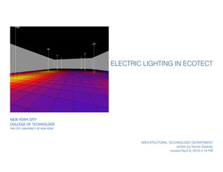
- 1. New York City College of Technology The City University of New York Electric Lighting in Ecotect Architectural technology department written by Nicole Seekely revised April 6, 2010 4:14 PM
- 2. Notes: Remember, if you want to change your units, go to File - User Preferences - Locali- sation. You can also change the default zone height in the Modeling tab. You can change the snap distance in the Cursor Snap tab. I’ve set mine to 3”. page 2 of 11 Electric Lighting in Ecotect Step One: Create a room by clicking on the zone button and drawing a space. Once you’ve clicked the last point, hit Escape to finish. When drawing the zone, you can type in the values by moving the cursor in the axis you want and then type the distance desired followed by Enter.
- 3. Notes: page 3 of 11 Electric Lighting in Ecotect Step Two: Create a light at the same height of the ceiling. To do this, click on the light button on the left side of the screen. Step Three: Move your cursor over the point you want the light. It will automatically be placed on the ground plan. To change the height it will be placed, hold down Ctrl to move the cursor in the Z axis. This will allow you to snap to the roof.
- 4. Notes: page 4 of 11 Electric Lighting in Ecotect Step Four: Click once to place the light. Then hit F6 or F7 to move to Side/Front view. Click a second time to place the direction of the light. You should see a cone of light. Click F8 to go back to Perspective.
- 5. Notes: To properly mirror objects, you may need to adjust the mirror origin. Do this by selecting the Mirror button, then move your cursor over the mirror origin axis until an O ap- pears. Click your mouse once there and then again at the new origin point. Then click the two points you want to mirror over. page 5 of 11 Electric Lighting in Ecotect Step Five: With the light selected, go to the Object Transforma- tions tab. Under Linear Array, specify the spacing and num- ber of lights you want arrayed. Then click Create Array. Step Six: Move the arrayed lights to one side of the room if they’re not already, and mirror them so that you have two rows. When mirroring objects, make sure you have Apply to Copy box checked
- 6. Notes: page 6 of 11 Electric Lighting in Ecotect Step Seven: You can change the type of light by adjusting its material. With the light(s) selected, go go the Material Assignments tab. You can choose any of the premade lights or create your own.
- 7. Notes: Remember to use spacebar to change selected objects. page 7 of 11 Electric Lighting in Ecotect Step Eight: Select the floor and the go to the Analysis Grid tab. Select Display Analysis Grid and then select Auto-Fit Grid to Objects. The default should be okay, but you can adjust the height if you want (Axial Offset).
- 8. Notes: page 8 of 11 Electric Lighting in Ecotect Step Nine: At t he bottom of the Analysis Grid tab, click Perform Calcu- lation on Lighting Levels. Step 1 - Electric Light Levels Step 2 - Over the Analysis Grid (you can select 3D Ex- tents, but this will take longer) Step 3 - High Precision Step 4 - Calculate It for Me Step 5, 6, 7 - OK
- 9. Notes: The difference between the two rows of lights is because they are two different ma- terials. page 9 of 11 Electric Lighting in Ecotect Step Ten: Once the calculation is fin- ished, you will most likely have a Daylight Factor Analy- sis shown. To see just the electric light levels, scroll to the Electric Light Levels op- tion under Data & Scale.
- 10. Notes: page 10 of 11 Electric Lighting in Ecotect You can display the lighting values in 3D by clicking Show Values in 3D in the Analysis Grid menu.
- 11. Notes: page 11 of 11 Electric Lighting in Ecotect You can export the scene with electric lights just as before. Make sure to set your cam- era, then go to the Export tab, and export to Radiance.