SlideShare une entreprise Scribd logo
1  sur  102
Télécharger pour lire hors ligne
THERMO-ECONOMIC OPTIMIZATION OF ABSORPTION HEAT
TRANSFORMER
A dissertation submitted in partial fulfilment of the requirement for the
award of the degree of
MASTER OF TECHNOLOGY
IN
THERMAL ENGINEERING
By
NAVNEET
Roll No. 13161003
Under the Supervision of
Dr. MAHESH KUMAR
AND
Sh. PANKAJ KHATAK
Assistant Professor
Department of Mechanical Engineering
Guru Jambheshwar University of Science and Technology, Hisar
DEPARTMENT OF MECHANICAL ENGINEERING
GURU JAMBHESHWAR UNIVERSITY OF SCIENCE AND TECHNOLOGY
HISAR – 125001 (JUNE 2015)
i
CANDIDATE’S DECLARATION
I hereby certify that the work which is being presented in this dissertation
entitled “THERMO-ECONOMIC OPTIMIZATIO OF ABSORPTION HEAT
TRANSFORMER” for the award of the degree of Master of Technology in
Mechanical Engineering submitted in the Department of Mechanical Engineering,
Guru Jambheshwar University of Science and Technology, Hisar, is an authentic
record of my own work carried out under the supervision of my guide Dr. Mahesh
Kumar and Sh. Pankaj Khatak, Department of Mechanical Engineering, Guru
Jambheshwar University of Science and Technology, Hisar.
The matter presented in this thesis has not been submitted by me for the
award of any degree/diploma of this or any other University/Institute.
Date: NAVNEET
Roll No. 13161003
ii
CERTIFICATE
This is to certify that the thesis entitled “THERMO-ECONOMIC OPTIMIZATION OF
ABSORPTION HEAT TRANSFORMER” being submitted by Navneet (Roll No.
13161003) to the Department of Mechanical Engineering, Guru Jambheshwar
University of Science and Technology, Hisar for the award of the Degree of Master
of Technology in Mechanical Engineering, is a bona fide work carried out by him
under my supervision and guidance. The results presented have not been submitted
in part or in full to any other University/Institute for the award of any degree or
diploma.
Sh. PANKAJ KHATAK Dr. MAHESH KUMAR
Assistant Professor Assistant Professor
Department of Mechanical Engineering
Guru Jambheshwar University of Science and Technology
Hisar
iii
ACKNOWLEDGEMENT
The sense of contentment and elation that accompanies the successful completion
of dissertation work would be incomplete without mentioning the names of people who
helped in accomplishment of this work.
I wish to thank Dr. Vishal Gulati, Chairman, Department of Mechanical
Engineering, Guru Jambheshwar University of Science and Technology, Hisar.
I would like to thank my teacher and thesis guide Dr. Mahesh Kumar and Co-
guide Sh. Pankaj Khatak, Department of Mechanical Engineering, Guru Jambheshwar
University of Science and Technology for their valuable guidelines and constant support.
I would like to express my heartfelt gratitude to Dr. Gulsahn Sachdeva,
Department of Mechanical Engineering, National Institute of Technology, Kurukshetra
(Haryana) for providing the technical support.
I am thankful to Mr. Vaibhav Jain, Department of Mechanical and Automation
Engineering, Maharaja Agrasen Institute of Technology, Delhi (India) for providing his
support.
Finally, I wish to thank my family, my teachers and my friends who have
constantly motivated me and helped me directly or indirectly in the accomplishment of
this work.
NAVNEET
iv
ABSTRACT
Almost every industrial process requires thermal energy and this energy is mainly
provided by the burning of the fossil fuels. After carrying out the processes in industries,
heat is rejected to the surroundings as waste with its temperature varying from 40°C
to70°C. Upgrading the low temperature rejected heat to higher temperature heat can be a
step towards the sustainable development of any nation as the gain in the quality of heat
makes it possible to use it in other applications. In Today’s world, most of the countries
are investing substantial amount of money in the up gradation of resources and equipment
that can be able to recover waste heat and will provide the efficient way of utilizing the
primary sources of energy. Waste heat is the heat, which is generated in a process by way
of fuel consumption or chemical reaction, and dumped in the environment even through it
could still be reused for some useful and economic purposes. Energy is the inseparable
item that governs our lives and promotes civilization. Amongst various possibilities,
absorption heat transformer is an attractive option with minimum consumption of high
grade energy i.e. electricity and low maintenance cost.
In this investigation, thermo-economic optimization of a 2kW LiBr-H2O incorporated
AHT has been presented. The critical study of AHT literature reveals that very less work
was performed related to the sizing, total cost and relation between size and cost of AHT
system. For simplified design of AHT system equation of mass and energy balance and
for exergy analysis, modified Gouy - Stodola equation were simulated by EES software
and computer codes were developed in EES. Heat transfer coefficients were found by
different correlation used and various properties of LiBr-H2O solution were reproduced
by EES. The purposed AHT system uses LiBr-H2O mixture using water as refrigerant and
LiBr mixture as absorbent. The equations used in this analysis were defined which
provides basis for forming a computer code. For absorber and evaporator single pass
v
vertical tube heat exchangers were assumed whereas for condenser and generator single
pass horizontal tube heat exchangers were assumed. Also, the solution heat exchanger
was designed assuming single pass annular heat exchanger. The goal of this work is to
optimize the AHT thermally as well as economically by minimize its total cost. Total cost
of AHT consists of investment cost, running cost and recovery cost. AHT system is
devices with the unique capability of raising the temperature of low or moderately warm
waste heat source to more useful levels. This study includes a mathematical investigation
to analyze the AHT system. The accuracy of the basis code of input variables was
estimated by comparing it with the data presented for the second model of AHT in
Ilhami,s different models of AHT. The results show good accuracy in this analysis. The
COP of the model developed is found 0.4528 where as Carnot COP is 0.75. Also the total
irreversibility of system by modified Gouy – Stodola method is 2.491kW and
irreversibility by Gouy – Stodola equation is 1.276kW and total annual operating cost of
the system is 593.3$. It is also analyzed that an increase in generator temperature and
decrease in condenser and absorber temperature increases the COP, minimize the total
irreversibility and total cost of the system. The high value of absorber temperature is
limited because increase in absorber temperature decreases COP and increases the mass
of LiBr in the system. In this analysis temperature lift of 30o
C was obtained by upgrading
waste heat at 80o
C to 110o
C.
vi
CONTENTS
Page no.
Candidate’s Declaration i
Certificate ii
Acknowledgement iii
Abstract iv
Contents vi
List of figures ix
List of tables x
Nomenclature xii
1. INTRODUCTION
1.1 History
1.2 Necessity of absorption system
1.3 Background
1.3.1 Absorption introduction
1.3.2 Similarities between VC and VA cycles
1.3.3 Differences between VC and VA cycles
1.3.4 Basic principle of absorption system
1.3.5 Working fluids for VAR system
1.3.6 Application of absorption system
1.4 Various configurations of VAR
1.4.1 Single effect absorption refrigeration
1.4.2 Absorption heat transformer
1.4.3 Multi-effect absorption refrigeration
1-19
3
3
5
5
7
8
9
11
13
14
14
16
17
2. LITERATURE REVIEW
2.1 Literature survey related to VAR systems
2.2 Literature survey related to AHT systems
2.3 Literature Gap
2.4 Objective of present work
20-32
20
25
30
31
vii
3. SYSTEM DESCRIPTION
3.1 Absorption heat transformer
3.1.1 Basic working cycle of AHT
3.1.2 Function of various component of AHT
3.1.3 Efficiency of AHT system
3.1.4 Key characteristics of LiBr-H2o absorption system
3.2 Practical problems
3.2.1 Crystallization
3.2.2 Air leakage
3.2.3 Corrosion of components
3.3 Capacity control
3.4 AHT working fluids
3.5 AHT operating conditions
33-43
33
34
36
39
39
40
40
41
41
42
42
43
4. MODELLING AND PERFORMANCE ANALYSIS
4.1 Model development
4.2 Assumptions in mathematical modelling
4.3 Mathematical modelling
4.4 Calculation procedure
4.5 Validation of mathematical modelling
4.6 First law analysis of AHT system
4.7 Effect of various operating parameters on COP
4.7.1 Effect of absorber temperature
4.7.2 Effect of generator temperature
4.7.3 Effect of condenser temperature
4.7.4 Effect of evaporator temperature
4.8 Second law analysis of absorption heat transformer
4.9 Effect of operating parameters on irreversibility of the system
4.9.1 Effect of absorber temperature
4.9.2 Effect of generator temperature
4.9.3 Effect of condenser temperature
4.9.4 Effect of evaporator temperature
44-59
44
45
45
49
49
51
52
52
54
54
55
55
56
56
57
58
59
viii
5. COMPONENT DESIGNING
5.1 Heat exchanger sizing
5.1.1 Calculation of inside heat transfer coefficient
5.1.2 Calculation of outside heat transfer coefficient
5.2 Condenser heat exchanger design
5.3 Generator heat exchanger design
5.4 Evaporator heat exchanger design
5.5 Absorber heat exchanger design
5.6 Solution heat exchanger design
6. COST ANALYSIS
6.1 Exergy input cost
6.2 Electric energy input cost
6.3 Investment cost
7. THERMO-ECONOMIC OPTIMIZATION
7.1 Effect of absorber temperature
7.2 Effect of generator temperature
7.3 Effect of condenser temperature
7.4 Effect of evaporator temperature
60-71
60
61
61
62
63
65
67
69
72-75
72
73
74
76-83
76
77
80
81
6. CREDENTIALS
7. REFERENCES
84
85-87
ix
LIST OF FIGURES
Figure
no.
Description Page no.
Fig .1 Vapour compression refrigeration system 5
Fig .2 Vapour absorption refrigeration system 6
Fig .3 Principle of absorption system 10
Fig .4 Single effect LiBr-water absorption refrigeration 15
Fig .5 Absorption heat transformer 17
Fig .6 Double effect absorption refrigeration 18
Fig .7 Absorption heat transformer with Libr-water pair 34
Fig .8 Pressure temperature diagram of AHT 36
Fig .9 Schematic diagram of AHT using waste heat source 46
Fig .10 Effect of TAB on COP of system 53
Fig .11 Effect of TGE on COP of system 53
Fig .12 Effect of TCO on COP of system 54
Fig .13 Effect of TEV on COP of system 55
Fig .14 Effect of TAB on irreversibility 57
Fig .15 Effect of TGE on irreversibility 57
Fig .16 Effect of TCO on irreversibility 58
Fig .17 Effect of TEV on irreversibility 59
Fig .18 Effect of TAB on different areas 77
Fig .19 Effect of TAB on total cost 78
Fig .20 Effect of TGE on different areas 78
Fig .21 Effect of TGE on total cost 79
Fig .22 Effect of TCO on different areas 80
Fig .23 Effect of TCO on total cost 81
Fig .24 Effect of TEV on different areas 82
Fig .25 Effect of TEV on different areas 82
x
LIST OF TABLES
Table
no.
Description Page no.
Table 1 Boiling point of water at different pressure 9
Table 2 Ilhami’s inputs 50
Table 3 Validation of AHT modelling 50
Table 4 Fixed data in the analysis 51
Table 5 First law results of AHT 51
Table 6
Table 7
Various properties at different state points
Second law results
52
56
Table 8 Characteristics of condenser 62
Table 9 Specifications for condenser 63
Table 10 Characteristics of generator 64
Table 1 Specifications for generator 65
Table 12 Characteristics of evaporator 66
Table 13 Specifications for evaporator 67
Table 14 Characteristics of absorber 68
Table 15 Specification for absorber 69
Table 16 Characteristics of solution heat exchanger 69
Table 17 Specification of solution heat exchanger 70
Table 18 Configuration of various components of AHT 71
xi
LIST OF GRAPHS
Graph Title Page no.
Graph 1 Effect of condenser temperature on the COP of the
system
51
Graph 2 Effect of generator temperature on the COP of the
system
52
Graph 3 Effect of absorber temperature on the COP of the system 53
Graph 4 Effect of evaporator temperature on the COP of the
system
53
xii
NOMENCLATURE
H Enthalpy
U Overall heat transfer coefficient
Q Heat rate
M mass flow rate
A Area
To environmental temperature
Cp specific heat at constant pressure
∆Tm Log mean temperature difference
D
hi
F
ReD
Pr
NuD
Γ
µ
k
ρ
hfg
x
AHT
VAR
SHX
PRV
Diameter
Inside heat transfer coefficient
Fouling factor
Reynolds number
Prandtl number
Nusselt’s number
Solution flow rate per unit length
Dynamic viscosity
Thermal conductivity
Density
Latent heat of vaporization
Mass fraction of LiBr
Absorption heat transformer
Vapour absorption refrigeration
Solution heat exchanger
Pressure reducing valve
xiii
COP Coefficient of performance
TAB Absorber temperature
TGE Generator temperature
TEV Evaporator temperature
TCO Condenser temperature
GTL Gross temperature lift
ΔTo Temperature difference of outgoing fluid
ΔTi Temperature difference of incoming fluid
𝜌𝑙 Density of liquid
𝜌𝑣 Density of vapour
g Acceleration due to gravity
µl Dynamic viscosity of liquid
Bi Total exergy input
ho Enthalpy of water at To
So Entropy of water at To
P4 Pressure in evaporator and absorber
P2 Pressure in condenser and generator
1
CHAPTER 1
INTRODUCTION
The development of any nation of the world depends on the amount of energy it has or
sources of energy it contained. Sources of energy involve renewable energy sources and
non renewable energy sources. Non-renewable energy resources are coal, petrochemical
and gas etc. Most of the energy demand is satisfied through non-renewable energy
resources. But these resources are limited in amount. So by using these resources, future
of the upcoming generation will be in danger. Renewable energy sources are sun, water,
wind etc. But till now we are not able to use these sources efficiently and economically.
On the other hand the demand of energy is growing and the energy sources available are
becoming scare and costlier. In the energy demand and supply side developing nations
including India, are facing severe shortage. Huge amount of energy and tremendous
efforts are required for meeting these future demands. There is need of generating new
energy sources and up gradation of present resources. In today’s world most of the
countries are investing substantial amount of money in the up gradation of resources and
equipments that can be able to recover waste heat and provide the efficient way of using
the primary sources of energy. Also scientists are working on the efficient use of
renewable sources of energy. The heat which is generated by way of fuel burning or
through chemical reaction, is used in a process and the remaining waste heat is dumped in
the environment even it still possess some energy. Waste heat is generally available at
low temperature, which can’t be utilized directly. For making this waste heat useful, an
up gradation in temperature is required, also as the heat at high temperature is more
significant than the heat at low temperature. Irrespective of oil and gas, the need to further
utilize this rejected energy is justified owing to the fact that the oil and gas reserves are
ever decreasing. The essential quality of heat is not the amount but rather its ‘value’ i.e.
2
temperature. The strategy of how to recover the heat depends on the temperature of waste
heat gases and cost involved. Large quantity of hot fuel gases are generated from boilers,
ovens and furnace etc. If some of this waste heat could be recovered by up grading its
temperature, a considerable amount of primary fuel could be saved. However, the energy
lost in waste heat gases can’t be fully recovered. In addition to the recovery of waste heat
we can have direct and indirect benefits. Direct advantages are direct effect on efficiency
of the process, less process cost and utility consumption. Indirect advantages are
reduction in pollutants, auxiliary energy saving and reduction in equipment size. There
are number of ways of up grading or recovering waste heat. Amongst various
possibilities, absorption heat transformer (AHT) is an attractive option with minimum
consumption of high grade energy i.e. electricity and low maintenance cost. AHT systems
which are operated on absorption cycle may also be incorporated with renewable source
of energy like solar etc. As solar system is the prominent producer of abundance of low
grade energy or low temperature energy on our planet Earth. By the use of absorption
technologies, waste heat can be converted to useful refrigeration by using heat operated
refrigeration system or vapour absorption refrigeration (VAR) system and can be
upgraded to more useful level with the use of absorption heat transformer. By using VAR
system, electricity purchased from utility companies for conventional vapour compression
refrigerators can be reduced. The use of heat operated AHT system helps to reduce
problems related to global environmental, such as the so called greenhouse effect from
CO2 emission from the combustion of fossil fuels in utility power plants. Small size AHT
system can be installed in domestic region for water desalination, cooking etc. However,
absorption system seems to provide many advantages, but still they are rarely available.
In order to promote the use of absorption systems, further development is required to
3
develop domestic absorption system, also as future prospective there is need of improving
their performance and reducing system cost.
1.1 HISTORY
The early development of an absorption cycle dates back to the 1700’s. It was known that
ice could be produced by an evaporation of pure water from a vessel contained within an
evacuated container in the presence of sulphuric acid. In 1810, ice could be made from
water in a vessel, which was connected to another vessel containing sulphuric acid. As the
acid absorbed water vapour, causing a reduction of temperature, layers of ice were
formed on the water surface. The major problems of this system were corrosion and
leakage of air into the vacuum vessel. In 1859, Ferdinand Carre introduced a novel
machine using water and ammonia as the working fluid. This machine took out a US
patent in 1860. Machines based on this patent were used to make ice and store food. It
was used as a basic design in the early age of refrigeration development. In the 1950’s, a
system using lithium bromide/water as the working fluid was introduced for industrial
applications. A few years later, a double-effect absorption system was introduced and has
been used as an industrial standard for a high performance heat-operated refrigeration
cycle.
1.2 NECESSITY OF ABSORPTION SYSTEMS
Almost every industrial process requires thermal energy and this energy is mainly
provided by the burning of the fossil fuels which produce greenhouse gases such as CO2,
methane etc. cause global warming. Global warming (due to greenhouse gas
accumulation in the lower atmosphere) and stratospheric ozone depletion are increasingly
recognized as two coexistent, partly-related processes threatening to upset the ecological
support system of the Earth. A recent analysis of the potential public-health impact of
4
climate change concluded that a few degrees increase of average global temperature
would lead to, increased incidence of heat strokes and heat-related death in chronic
diseases, geo-graphic shifts in tropical and infectious diseases; increased occurrence of
death, injury and epidemics due to weather-related emergencies and flooding of coastal
areas. In order to curb the global warming and ozone depletion, two important documents,
The United Nations Framework Convention on Climate Change (FCCC) and Montreal
Protocol, were signed by many countries. According to these two documents, CFC and
HCFC fluids, which are widely used in vapour-compression refrigerators and heat pumps
will be gradually phased out and the emission of greenhouse gas CO2 should be reduced
to their 1990 levels. In some EU countries, this ban extends to HFC fluids. The ban on
CFC, HCFC and HFC fluids has encouraged research into environmental friendly
refrigerants such as water. Apart from reducing fossil-fuel consumption, improving the
efficiency of the refrigerators and heat pumps and utilization of low-grade energy are the
effective ways to reduce CO2 emissions. For the latter, AHT cycles can provide the
answer. The vapour-absorption cycle is considered to be the best in terms of energy
performance today and it has potential to be improved among the several heat-powered
cycles. Compared with the vapour-compression cycle, the absorption cycle has a
reputation of low efficiency although this is a result of unfair comparison between them,
but the environmental concern calls for high efficiency, no pollution refrigerators and
heat pumps. In recent years, finding ways to improve absorption-system efficiency has
been a great challenge for researchers. Works were mainly focused on inventing new or
hybrid cycles, finding new working fluids and improving the heat and mass transfers of
the absorption systems.
5
1.3 BACKGROUND
1.3.1 Absorption Introduction
Comparing the absorption refrigeration cycle with the more familiar vapour compression
refrigeration cycle is often an easy way to introduce it. The standard vapour compression
refrigeration system is a condenser, evaporator, throttling valve, and a compressor. Fig.1 below is
a schematic of the components and flow arrangements for the vapour compression cycle. In the
vapour-compression refrigeration cycle, refrigerant enters the evaporator in the form of a cool,
low-pressure mixture of liquid and vapour (4). Heat is transferred from the relatively warm air or
water to the refrigerant, causing the liquid refrigerant to boil. The resulting vapour (1) is then
pumped from the evaporator by the compressor, which increases the pressure and temperature of
the refrigerant vapour. The hot, high-pressure refrigerant vapour (2) leaving the compressor enters
the condenser where heat is transferred to ambient air or water at a lower temperature.
Fig.1 Vapour Compression Refrigeration System
Inside the condenser, the refrigerant vapor condenses into a liquid. This liquid refrigerant
(3) then flows to the expansion device, which creates a pressure drop that reduces the
2
2
Win
33
1
1
4
3
3
3
Condenser
Evaporator
Compress
or
Qout
Expansion
Valve
Qin
6
pressure of the refrigerant to that of the evaporator. At this low pressure, a small portion
of the refrigerant boils (or flashes), cooling the remaining liquid refrigerant to the desired
evaporator temperature. The cooled mixture of liquid and vapor refrigerant (4) then
travels to the evaporator to repeat the cycle. Much like in the vapor compression cycle,
refrigerant in the absorption cycle flows through a condenser, expansion valve, and an
evaporator. However, the absorption cycle uses different refrigerants and a different
method of compression than the vapor compression cycle. Absorption refrigeration
systems replace the compressor with a generator and an absorber as shown in Fig.2. In
absorption refrigeration systems, refrigerant enters the evaporator in the form of a cool,
low-pressure mixture of liquid and vapor (4).
Fig. 2 Vapour Absorption Refrigeration System
Heat is transferred from the relatively warm water to the refrigerant, causing the liquid
refrigerant to boil. Using an analogy of the vapour compression cycle, the absorber acts
Qout
3 2
Expansion valve
4
7
Qin
6
8 5
Pump
1
Condense
r
Generator
Absorber
Evaporato
r
Qin Qout
7
like the suction side of the compressor—it draws in the refrigerant vapour (1) to mix with
the absorbent. The pump acts like the compression process itself—it pushes the mixture
of refrigerant and absorbent up to the high-pressure side of the system. The generator acts
like the discharge of the compressor—it delivers the refrigerant vapour (2) to the rest of
the system. The refrigerant vapour (2) leaving the generator enters the condenser, where
heat is transferred to water at a lower temperature, causing the refrigerant vapour to
condense into a liquid. This liquid refrigerant (3) then flows to the expansion device,
which creates a pressure drop that reduces the pressure of the refrigerant to that of the
evaporator. The resulting mixture of liquid and vapour refrigerant (4) then travels to the
evaporator to repeat the cycle.
1.3.2 Similarities between Vapor Compression and Vapor Absorption Cycles
The basic absorption chiller cycle is similar to the traditional vapor compression chiller
cycle in that
1. Both cycles circulate refrigerant inside the chiller to transfer heat from one fluid to the
other;
2. Both cycles include a device to increase the pressure of the refrigerant and an
expansion device to maintain the internal pressure difference, which is critical to the
overall heat transfer process;
3. Refrigerant vapor is condensed at high pressure and temperature, rejecting heat to the
surroundings;
4. Refrigerant vapor is vaporized at low pressure and temperature, absorbing heat from
the chilled water flow.
8
1.3.3 Differences between Vapor Compression and Vapor Absorption Cycles
The basic absorption chiller cycle is different to the vapor compression chiller cycle in
that
1. The absorption systems use heat energy in form of steam, direct fuel firing or waste
heat to achieve the refrigerant effect;
2. The absorption cycle use a liquid pump, NOT a compressor to create the pressure rise
between evaporator and condenser. Pumping a liquid is much easier and cheaper than
compressing a gas, so the system takes less work input. However, there is a large heat
input in the generator. So, the system basically replaces the work input of a vapor-
compression cycle with a heat input;
3. The absorption cycle uses different refrigerants that have no associated environment
hazard, ozone depletion or global warming potential (for example lithium bromide
absorption system use distilled water as the refrigerant). The vapor compression
refrigeration cycle generally uses a halocarbon (such as HCFC-123, HCFC-22, HFC-
134a, etc) as the refrigerant;
4. Compared to compression chillers, absorption systems contain very few moving parts,
offer less noise and vibration, are compact for large capacities and require little
maintenance;
5. Compared to compression chillers, the performance of absorption systems is not
sensitive to load variations and does not depend very much on evaporator superheat;
6. Compared with mechanical chillers, absorption systems have a low coefficient of
performance (COP = chiller load/heat input). However, absorption chillers can
substantially reduce operating costs because they are powered by low-grade waste heat.
The COP of absorption chiller is NOT sensitive to load variations and does not reduce
significantly at part loads. From the standpoint of thermodynamics, the vapor
9
compression chiller is a heat pump, using mechanical energy and work, to move heat
from a low to a high temperature. An absorption chiller is the equivalent of a heat engine
– absorbing heat at a high temperature, rejecting heat at a lower temperature, producing
work – driving a heat pump.
1.3.4 Basic Principle of Absorption System
Water boils and evaporates at 212 °F (100 °C) at standard atmospheric pressure
(101.3kPa). When the pressure is reduced, water boils at a lower temperature. The
following table gives the total pressure in mm of mercury and the corresponding
approximate water boiling temperature at different pressures. The fundamental principle
of vapour absorption machine is that water boils at about 40°F at the low-pressure
vacuum condition of 6.5 mm-Hg.
Table: 1 Boiling point of water at different pressures
The working fluid in an absorption refrigeration system is a binary solution consisting of
refrigerant and absorbent. Considering Fig 3, In Fig. 3(a) two evacuated vessels are
connected to each other. The left vessel contains liquid refrigerant while the right vessel
contains a binary solution of absorbent/refrigerant.
Absolute pressure Water boiling point (°C)
760 mm-Hg (1 atm) 100°
76 mm-Hg (0.1 atm) 46.11°
25.6 mm-Hg (0.34 atm) 26.67°
7.6 mm-Hg (0.01 atm) 7.22°
10
Fig.3. (a) Absorption process occurs in right vessel causing cooling effect in the
other; (b) Refrigerant separation process occurs in the right vessel as a result of
additional heat from outside heat source.
The solution in the right vessel will absorb refrigerant vapor from the left vessel causing
pressure to reduce. While the refrigerant vapor is being absorbed, the temperature of the
remaining refrigerant will reduce as a result of its vaporization. This causes a refrigeration
effect to occur inside the left vessel. At the same time, solution inside the right vessel
becomes more dilute because of the higher content of refrigerant absorbed. This is called
the “absorption process”. Normally, the absorption process is an exothermic process;
therefore, it must reject heat out to the surrounding in order to maintain its absorption
capability. Whenever the solution cannot continue with the absorption process because of
saturation of the refrigerant, the refrigerant must be separated out from the diluted
solution. Heat is normally the key for this separation process. It is applied to the right
vessel in order to dry the refrigerant from the solution as shown in Fig. 3(b). The
refrigerant vapor will be condensed by transferring heat to the surroundings. With these
processes, the refrigeration effect can be produced by using heat energy. However, the
cooling effect cannot be produced continuously as the process cannot be done
simultaneously. Therefore, an absorption refrigeration cycle is a combination of these two
processes refrigerant absorption and separation process. As the separation process occurs
Refrigerant Solution
Q
H
Q
I
Fig. 3(b)
Refrigerant Solution
Q
I
Q
L
Fig. 3(a)
11
at a higher pressure than the absorption process, a circulation pump is required to
circulate the solution. Coefficient of Performance of an absorption refrigeration system is
obtained from;
𝐶𝑂𝑃 =
𝑅𝑒𝑓𝑟𝑖𝑔𝑒𝑟𝑎𝑡𝑖𝑛𝑔 𝐸𝑓𝑓𝑒𝑐𝑡 𝑃𝑟𝑜𝑑𝑢𝑐𝑒𝑑 𝑖𝑛 𝐸𝑣𝑎𝑝𝑜𝑟𝑎𝑡𝑜𝑟
𝐻𝑒𝑎𝑡 𝑖𝑛𝑝𝑢𝑡 𝑖𝑛 𝐺𝑒𝑛𝑒𝑟𝑎𝑡𝑜𝑟 + 𝑃𝑢𝑚𝑝 𝑊𝑜𝑟𝑘 𝑖𝑛𝑝𝑢𝑡
The work input for the pump is negligible relative to the heat input at the generator;
therefore, the pump work is often neglected for the purposes of analysis.
1.3.5 Working Fluid for Vapour Absorption Refrigeration Systems
Performance of an absorption refrigeration system is critically dependent on the chemical
and thermodynamic properties of the working fluid. A fundamental requirement of
absorbent/refrigerant combination is that, in liquid phase, they must have a margin of
miscibility within the operating temperature range of the cycle. The mixture should also
be chemically stable, non-toxic, and non-explosive. In addition to these requirements, the
following are desirable.
 The elevation of boiling (the difference in boiling point between the pure
refrigerant and the mixture at the same pressure) should be as large as possible.
 Refrigerant should have high heat of vaporization and high concentration within
the absorbent in order to maintain low circulation rate between the generator and
the absorber per unit of cooling capacity.
 Transport properties that influence heat and mass transfer, e.g., viscosity, thermal
conductivity, and diffusion coefficient should be favourable.
 Both refrigerant and absorbent should be non-corrosive, environmental friendly,
and low-cost.
12
Many working fluids are suggested in literature. A survey of absorption fluids provided
by Marcriss suggests that, there are some 40 refrigerant compounds and 200 absorbent
compounds available. However, the most common working fluids are Water-NH3 and
LiBr-water. Since the invention of an absorption refrigeration system, water-NH3 has
been widely used for both cooling and heating purposes. Both NH3 (refrigerant) and water
(absorbent) are highly stable for a wide range of operating temperature and pressure. NH3
has a high latent heat of vaporization, which is necessary for efficient performance of the
system. It can be used for low temperature applications, as the freezing point of NH3 is -
77.73°C. Since both NH3 and water are volatility, the cycle requires a rectifier to strip
away water that normally evaporates with NH3. Without a rectifier, the water would
accumulate in the evaporator and offset the system performance. There are other
disadvantages such as its high pressure, toxicity, and corrosive action to copper and
copper alloy. However, water/NH3 is environmental friendly and low cost. The use of
LiBr/water for absorption refrigeration systems began around 1930. Two outstanding
features of LiBr/water are non-volatility absorbent of LiBr (the need of a rectifier is
eliminated) and extremely high heat of vaporization of water (refrigerant). However,
using water as a refrigerant limits the low temperature application to that above 0°C. As
water is the refrigerant, the system must be operated under vacuum conditions. At high
concentrations, the solution is prone to crystallization. It is also corrosive to some metal
and expensive. Some additive may be added to LiBr-water as a corrosion inhibitor or to
improve heat-mass transfer performance. Although LiBr-water and water-NH3 have been
widely used for many years and their properties are well known, much extensive research
has been carried out to investigate new working fluids. Fluorocarbon refrigerant-based
working fluids have been studied. R22 and R21 have been widely suggested because of
their favourable solubility with number of organic solvents. The two solvents, which have
13
stood out are Dimethyl Ether of Tetraethylene Glycol (DMETEG) and Dimethyl
Formamide (DMF). Research on these kinds of working fluids may be obtained from the
literature. A binary mixture using inorganic salt absorbent such as LiBr-water or NaOH-
water may be the most successful working for an absorption refrigeration system.
However, at high concentration such as at low temperature, the solution is prone to
crystallization. It was found that the addition of a second salt as in a ternary mixture such
as LiBr+ZnBr2-water can improve the solubility of the solution. Various ternary mixtures
have been tested for using with an absorption system by various researchers.
1.3.6 Applications of Absorption Systems
The main advantage of absorption systems is their ability to utilize waste heat streams
that would be otherwise discarded. In terms of energy performance, motor-driven vapour
compression chillers will beat absorption systems every time. Still there are specific
applications where absorption systems have a substantial advantage over motor-driven
vapour compression chillers. Some of those applications include:
1. For facilities that use lot of thermal energy for their processes, a large chunk of heat is
usually discarded to the surrounding as waste. This waste heat can be converted to useful
refrigeration by using a VAM and can be upgraded to more useful levels by using AHT
system which can be further utilized for any process requirement.
2. For facilities that have a simultaneous need for heat and power (cogeneration system),
absorption chillers can utilize the thermal energy to produce chilled water.
3. For facilities where the electrical supply is not robust, expensive, unreliable, or
unavailable, it is easier to achieve heat input with a flame than with electricity.
Absorption systems uses very little electricity compared to an electric motor driven
compression systems.
14
4. For facilities, where the cost of electricity verses fuel oil/gas tips the scale in favour of
fuel/gas. Various studies indicate that the absorption systems provide economic benefit in
most geographical areas, due to the differential in the cost between gas and electric
energy.
5. For facilities wanting to use a “natural refrigerant and aspiring for LEED certification
(Leadership in Energy and Environmental Design) absorption systems are a good choice.
Absorption devices do not use CFCs or HCFCs - the compounds known for causing
Ozone depletion.
6. For facilities implementing clean development mechanism (CDM) and accumulating
carbon credits, the absorption use coupled to waste heat recovery and cogeneration
system help reduce problems related to greenhouse effect from CO2
emission.
Vapour absorption system allows use of variable heat sources: directly using a gas burner,
recovering waste heat in the form of hot water or low-pressure steam, or boiler-generated
hot water or steam.
1.4 VARIOUS CONFIGURATIONS OF VAPOUR ABSORPTION SYSTEMS
1.4.1 Single-effect Absorption Refrigeration
A single-effect absorption refrigeration system is the simplest and most commonly used
design. Both vapour absorption refrigerator (VAR) and absorption heat pump (AHP)
operates on the same cycle, where as absorption heat transformer works on reverse
absorption refrigeration cycle.Fig.4 shows a single-effect system using non-volatility
absorbent such as LiBr/water. In VAR and AHP system both generator and condenser are
maintained at high pressure and absorber with evaporator maintained at low pressure.
High temperature heat supplied to the generator is used to evaporate refrigerant out from
15
the solution (rejected out to the surroundings at the condenser) and is used to heat the
solution from the absorber temperature (rejected out to the surroundings at the absorber).
Fig. 4 Single-effect LiBr-water Absorption Refrigeration
Thus, irreversibility is caused as high temperature heat of the generator is wasted out at
the absorber and the condenser. In order to reduce this irreversibility, a solution heat
exchange is introduced as show in Fig. 4. The heat exchanger allows the solution from the
absorber to be preheated before entering the generator by using the heat from the hot
solution leaving the generator. Therefore, the COP is improved as the heat input at the
generator is reduced. Moreover, the size of the absorber can be reduced as less heat is
rejected. Experimental studies shows that COP can be increased up to 60% when a
solution heat exchanger is used. When volatility absorbent such as water-NH3 is used, the
system requires an extra component called “a rectifier”, which will purify the refrigerant
before entering the condenser. As the absorbent used (water) is highly volatile, it will be
evaporated together with ammonia (refrigerant). Without the rectifier, this water will be
condensed and accumulate inside the evaporator, causing the performance to drop. Even
if the most common working fluids used are LiBr-water and water-NH3, various
QC
Expansion valve
QE, Ref. effect
QA
Generator
Absorber Evaporator
Condenser
SHX
QG, High
Pump
16
researchers have studied performance of a single-effect absorption system using other
kinds of working fluids such as LiNO3-NH3, LiBr+ZnBr2-CH3OH,
LiNO3+KNO3+NaNO3-water, LiCl-water, Glycerol-water etc.
1.4.2 Absorption Heat Transformer
Any absorption refrigeration cycle exchanges heat with three external reservoirs; low,
intermediate, and high temperature levels. When an absorption system is operated as a
refrigerator or a heat pump, the driving heat is supplied from the high temperature
reservoir. Refrigeration effect is produced at a low temperature level and rejects heat out
at an intermediate temperature level. The difference between them is the duty. For a
refrigerator, the useful heat transfer is at a low temperature. For the heat pump, the useful
heat transfer is at an intermediate temperature. Normally, the surrounding is used as a low
temperature reservoir for a heat pump or as an intermediate temperature reservoir for the
refrigerator. Another type of absorption cycle is known as “an absorption heat
transformer” or “a reverse absorption heat pump”. This system uses heat from an
intermediate temperature reservoir as the driving heat (normally from industrial waste
heat). The system rejects heat at a low temperature level (normally to the surroundings).
The useful output is obtained at the highest temperature level. The use of an absorption
heat transformer allows any waste heat to be upgraded to a higher temperature level
without any other heat input except some work required circulating the working fluid.
Fig. 5 shows a schematic diagram of an absorption heat transformer. This cycle has
similar components as a single-effect absorption cycle. The difference is that an
expansion device installed between the condenser and the evaporator is substituted by a
pump. Waste heat at a relatively low temperature is supplied to the generator for
refrigerant separation in the usual manner. Liquid refrigerant from the condenser is then
pumped to the evaporator with elevated pressure. Absorption heat transformer absorbs
17
waste heat at the generator. Liquid refrigerant is pumped to the evaporator to absorb
waste heat. High temperature useful heat from the absorber is heat of absorption.
Fig. 5 Absorption heat transformer
In the evaporator, refrigerant is vaporized by using the same low temperature waste heat
used to drive the generator (absorption heat transformers are usually operated at same
generator and evaporator temperatures). The vapour refrigerant is then absorbed into
solution in the absorber which rejects the useful heat out at a high temperature level.
Low-grade energy can be upgraded by using a heat transformer e.g. solar energy,
industrial waste heat.
1.4.3 Multi-effect Absorption Refrigeration
The main objective of a higher effect cycle is to increase system performance when high
temperature heat source is available. By the term “multi-effect”, the cycle has to be
configured in a way that heat rejected from a high-temperature stage is used as heat input
in a low-temperature stage for generation of additional cooling effect in the low-
temperature stage. Double-effect absorption refrigeration cycle was introduced during
1956 and 1958. Fig. 6 shows a system using LiBr-water as working pair.
EV
QG, Low Grade
QA, Useful
Pump
Evaporator
Absorber
SHX
Generator Condenser
QC
QE, Low Grade
18
Fig. 6 Double effect Absorption Refrigeration
High temperature heat from an external source supplies to the first-effect generator. The
vapour refrigerant generated is condensed at high pressure in the second-effect generator.
The heat rejected is used to produce addition refrigerant vapour from the solution coming
from the first-effect generator. This system configuration is considered as a series-flow-
double-effect absorption system. A double-effect absorption system is considered as a
combination of two single effect absorption systems whose COP value is COP single. For
one unit of heat input from the external source, cooling effect produced from the
refrigerant generated from the first-effect generator is 1×COP single. For any single-effect
absorption system, it may be assumed that the heat rejected from the condenser is
approximately equal to the cooling capacity obtained. Thus the heat supply to the second
generator is 1×COPsingle. The cooling effect produced from the second-effect generator
is (1×COP single) × COP single. Therefore, the COP of this double-effect absorption system
is COP double=COP single+ (COP single)2
. According to this analysis, a double effect
Generator I
Evaporator
Condenser
Absorber
HX II
HX I
Generator II
QH
QL
QI
QI
19
absorption system has a COP of 0.96 when the corresponding single-effect system has a
COP of 0.6. Theoretical studies of a double-effect absorption system have been provided
for various working fluids. If LiBr/water is replaced with water/NH3, maximum pressure
in the first-effect generator will be extremely high. Several types of multi-effect
absorption cycle have been analyzed by various researchers such as the triple effect
absorption cycle and the quadruple-effect absorption cycle. However, an improvement of
COP is not directly linked to the increment of number of effect. It must be noted that,
when the number of effects increase, COP of each effect will not be as high as that for a
single-effect system. Moreover, the higher number of effect leads to more system
complexity. Therefore, the double-effect cycle is the one that is available commercially.
20
CHAPTER 2
LITERATURE REVIEW
An extensive review of the literature has been done on different configuration of
absorption system. Related to the designing of AHT fewer work is available in literature.
The main idea was to have possible future direction of research. The literature review has
been classified as under:
1. Vapour Absorption Refrigeration System.
2. Vapour Absorption Heat Transformer.
2.1 LITERATURE SURVEY RELATED TO VAR SYSTEM
A large number of researchers have carried out research in the field of vapour absorption
refrigeration using different working pairs and the most common working pairs are LiBr-
H2O and NH3-H2O.
V. Jain et al [1] carried out thermo - economic optimization of vapour compression -
absorption cascaded refrigeration system (VCACRS) for water chilling application taking
R410a and water - LiBr as refrigerants in compression and absorption section
respectively. The main objective of optimization is to minimize the total annual cost of
system which comprises of costs of exergy input and capital cost in monetary units. The
appropriate set of decision variables (temperature of evaporator, condenser, generator,
absorber, cascade condenser, degree of overlap and effectiveness of solution heat
exchanger) minimizes the total annual cost of VCACRS by 11.9% with 22.4% reduction
in investment cost at the base case whereas the same is reduced by 7.5% with 11.7%
reduction in investment cost with reduced rate of interest and increased life span and
period of operation. The cascading of compression and absorption systems becomes
attractive for lower rate of interest and increase life span and operational period.
21
L. Garousi Farshi et al. [2] developed a computational model to study and compare the
effect of the operating parameters on crystallization phenomenon in three classes (series,
parallel and reverse parallel) of double effect LiBr – water absorption refrigeration
system. Crystallization of LiBr as it is a salt is very common so in their study they
purposed the air cooling system which is very attractive because the cooling tower and
associated and maintenance cost can be avoided. A computer program has been
developed using engineering equation solver (EES) software to carry out thermodynamic
analysis of absorption refrigeration system. In their study they found that the double
effect parallel and reverse parallel flow arrangements are superior in performance to
series flow in term of crystallization risk.
M. I. Karamangil et al. [3] studied the different literature on ARS and also studied the
thermodynamic analysis of ARS using different refrigerant – absorbent pair and user
friendly software was developed. The simulation result shows that COP of the system
improve with increase in the generator and evaporator temperature where as lower
condenser and absorber temperature is required. Also it was found that with the use of
SHE COP increased by 66% and with the use of RHE and SRHE COP increased only by
14 and 6% respectively. So SRHE may not be considered practically significant.
Alizadeh et al [4] carried out theoretical study on design and optimization of water –
LiBr refrigeration cycle. They concluded that for a given refrigerating capacity higher
generator temperature causes high cooling ratio with smaller heat exchange surface and
low cost. There is a limiting factor for water lithium bromide cycles because of the
problem of crystallization.
Anand and Kumar [5] carried out availability analysis and calculation of irreversibility
in system components of single and double effect series flow water lithium bromide
22
absorption systems. The assumed parameters for computation of results were condenser
and absorber temperature equal to 87.8o
C and 140.6o
C for single effect and double effect
systems respectively.
Tyagi [6] carried out the detailed study on aqua-ammonia VAR system and plotted the
coefficient of performance, mass flow rates as a function of operating parameters i.e.
absorber, evaporator and generator temperatures. He showed that COP and work done are
the function of evaporator, absorber, and condenser and generator temperature and also
depends on the properties of binary solution.
Aphornratana and Eames [7] investigated single effect water lithium bromide system
using exergy analysis approach. It was shown that the irreversibility in generator was
highest followed by absorber and evaporator.
Bell et al [8] developed a LiBr-H20 experimental absorption cooling system driven by
heat generated by solar energy. The components of the system are housed in evacuated
glass cylinders to observe all the processes. They determined the thermodynamic
performance of the system by applying mass and energy balance for all the components.
Their work was based on the assumption that the working fluids are in equilibrium and
the temperature of the working fluid leaving the generator and absorber is equal to the
temperature of generator and absorber respectively. They concluded that the COP of the
system depends on generator temperature and there is optimum value of generator
temperature at which the COP is maximum. They also concluded that by operating the
system at low condenser and absorber temperatures, a satisfactory COP is obtained at a
generator temperature as low as 68o
C.
Horuz [9] explained the fundamental vapour absorption refrigeration system and carried
out comparative study of such system based on ammonia-water and water lithium
bromide working pairs. The comparison of two systems is presented in respect of COP,
23
cooling capacity and maximum and minimum pressures. He concluded that VAR system
based on water-lithium bromide is better than ammonia-water. However, problem of
crystallization lies with water-lithium bromide system.
Lee and sheriff [10] carried out the second law analysis of a single effect water lithium
bromide absorption refrigeration system. The effect of heat source temperature on COP
and exergetic efficiency was evaluated. However, they did not analyzed effect of
variation in absorber and condenser temperatures and also the effectiveness of solution
heat exchanger was also not specified. Lee and sheriff carried out the second law analysis
of single effect and various double effect lithium bromide water absorption chillers for
chilled water temperature of 7.22o
C and cooling water temperatures 29.4o
C and 35o
C and
computed COP and exergetic efficiency. The effect of heat source temperature on COP
and exergetic efficiency was investigated. In this study, the effectiveness values of
solution heat exchangers considered for analysis has not been specified and their results
are only valid for water cooled systems.
Sozen [11] studied the effect of heat exchangers on the system performance in an
ammonia water absorption refrigeration system. Thermodynamic performance of the
system is analyzed and the irreversibility’s in the system components have been
determined for three different cases. The COP, ECOP, circulation ratio, and non
dimensional exergy loss of each component of the system is calculated. They concluded
that the evaporator, absorber, generator, mixture heat exchanger and condenser show high
non-dimensional exergy losses. They also concluded that using refrigerant exchanger in
addition to mixture heat exchanger does not increase the system performance.
De Francisco et al [12] developed and tested the prototype of a 2kW capacity water
ammonia absorption system operating on solar energy for rural applications. The system
also suffered from leakages in different components and need further improvements.
24
They concluded that the efficiency of the system is very low. The new and improved
prototype has to be developed.
Gomri and Hakimi [13] carried out exergy analysis of double effect lithium bromide-
water absorption refrigeration system. They showed that the performance of the system
increases with increasing LP generator temperature, but decreases with increasing HP
generator temperature. They concluded that the highest exergy loss occurs in the absorber
and in the HP generator and therefore the absorber and HP generator is the most
important component of the double effect refrigeration system.
Gomri [14] carried out the comparative study between single effect and double effect
absorption refrigeration systems. They developed the computer program based on energy
balances, thermodynamic properties to carry out thermodynamic analysis. They
concluded that for each condenser and evaporator temperature, there is an optimum
generator temperature where change in exergy of single effect and double effect
absorption refrigeration system is minimum. Their study showed that the COP of double
effect system is approximately twice the COP of single effect system but there is marginal
difference between the exergetic efficiency of the system.
Kaushik and Arora [15] presented the energy and exergy analysis of single effect and
series flow double effect water–lithium bromide absorption system. They developed the
computational model for parametric investigation. Their analysis involves the effect of
generator, absorber and evaporator temperatures on the energetic and exergetic
performance. They concluded that the irreversibility is highest in the absorber in both
systems as compared to other systems.
Zhu and Gu [16] used the first and second law of thermodynamic to analyze the
performance of ammonia–sodium thiocyanate absorption system for cooling and heating
applications. A mathematical model based on exergy analysis was developed. The
25
performance of the system is analyzed using different operating conditions. They
concluded that the cooling and heating COP increases with increasing generator and
evaporator temperatures but it decreases with increasing condenser and absorber
temperatures.
Florides et al [7] presents information on designing the heat exchangers of the LiBr–
water absorption unit. Single pass, vertical tube heat exchangers have been used for the
absorber and for the evaporator. The solution heat exchanger was designed as a single
pass annular heat exchanger. The condenser and the generator were designed using
horizontal tube heat exchangers. The calculated theoretical values are compared to
experimental results derived for a small unit with a nominal capacity of 1 kW. Finally, a
cost analysis for a domestic size absorber cooler is presented.
2.2 LITERATURE SURVEY RELATED TO AHT SYSTEM
Large number of literature is available on absorption heat transformer performance
analysis in terms of both energy and exergy, but very less literature is available regarding
designing of AHT systems.
Ilhami Horuz and Bener Kurt [18] AHT system using water-LiBr solution was
analyzed. In this analysis it was proved that, by applying different modifications, the COP
can be increased by 14.1%, the heat transfer at the absorber by 158.5% and the hot
process water produced by 3.59% compared to the basic AHT system. The waste heat can
be utilized by using the AHT system to generate the required energy demand. They
concluded that, as the condenser temperature increases, the COPs and the absorber heat
capacity decrease and when the evaporator and the generator temperatures increase, the
COPs and the absorber heat capacity increases. Also, if the evaporator temperature is
higher than the generator temperature, the AHT system performs better, i.e. the COP and
the absorber heat capacity increase and the higher flow ratio decreases the COP and the
26
absorber heat capacity. It was shown that by using the AHT system, about 50% of the
waste heat can be utilized and the process water hotter than the waste heat source
temperature can be produced.
Armando Huicochea et al [19] first and second laws of thermodynamics was used to
analyze the performance of an experimental absorption heat transformer for water
purification. Irreversibility, coefficients of performance (COP) and exergy coefficients of
performance (ECOP) were determined as function of the mass flow of hot water supplied
to the generator and as function of the overall thermal specific energy consumption
(OSTEC) parameter defined in this paper. They showed that the system irreversibility
increase meanwhile the coefficients of performance and the exergy coefficient of
performance decrease with an increment of the mass flow of hot water supplied to the
generator.
K.Abrahamsson et al [20] presents a 10 kW experimental absorption heat transformer
unit with self-circulation. The self-circulation was obtained by the thermo - syphon
principle. The pressure difference in the unit was achieved through a difference in
hydrostatic pressure. Theoretical relationships for the pressure profile within the different
component of heat transformer were derived. A satisfactory stable operation with self-
circulation was achieved.
W. Rivera et al [21] develop mathematical models of single-stage and advanced
absorption heat transformers operating with the water-lithium bromide and water-Carrol
mixtures to simulate the performance of the systems coupled to a solar pond in order to
increase the temperature of the useful heat produced by solar ponds. They showed that the
single-stage and the double absorption heat transformer are the most promising
configuration to be coupled to solar ponds. With single-stage heat transformers it is
possible to increase solar pond’s temperature until 50o
C with coefficients of performance
27
of about 0.48 and with double absorption heat transformers until 100o
C with coefficients
of performance of 0.33. The highest coefficients of performance were obtained with
single stage heat transformers. However, the gross temperature lifts reached with these
systems were the lowest. Comparing the two stage and double absorption heat
transformers, it was observed that almost the same COPs and DTs are obtained with both
systems at the same operating conditions.
W. Rivera et al [22] analyze the performance of an experimental single stage heat
transformer operating with the water/lithium bromide as single working pair and
subsequently, using 1-octanol and 2-ethyl-1-hexanol as additives. The enthalpy based
coefficients of performance (COP), external coefficients of performance (COPEXT),
exergy-based coefficients of performance (ECOP) and the irreversibility of the equipment
components were calculated for the main operating temperatures of the system. They
showed that for absorber temperatures between 84o
C and 88o
C the highest COP,
COPEXT, and ECOP are obtained with the use of the 2-ethyl-1-hexanol (400 parts per
million) additive, reaching values up to 0.49, 0.40 and 0.43, respectively. The lowest
coefficients of performance and highest irreversibility were obtained by using the single
water/lithium bromide mixture.
S. Sekar and R. Saravanan [23] vapour absorption heat transformer (VAHT) working
with water–lithium bromide (LiBr) solution, coupled with a seawater distillation system
of 5 kg/h distilled water capacity was tested to evaluate its performance. For this system,
the COP of 0.3 to 0.38 was obtained with the maximum distillate flow rate of 4.1 kg/h
and a recovery ratio of 0.17 to 0.23, under tested conditions. A maximum COP of 0.38
and a maximum temperature lift of 20°C were observed under tested conditions. They
concluded that, the system performance increased at lower condenser temperatures and
the distillate flow rate increases with an increase in the evaporation temperature.
28
Reyes et al [24] performance of AHT system with readily available, not expensive and
environmentally friendly fluids like the systems H2O-CaCl2 and H2O-LiCl were studied
by using a FORTRAN program. The theoretical performance of both systems in a single
stage absorption heat transformer (SSHT) was derived and compared to results obtained
previously for the system H2O-CaCl2 on a double absorption unit (DAHT). From
modelling results, better performance of the H2O-LiCl system in a SSHT can be expected
compared to that for the H2O-CaCl2 pair. However depending on every particular
application and for relatively low delivery temperatures, of about 80–100o
C, the use of
both systems is feasible. DAHT provide lower COP values and higher temperature lifts
compared to SSHT.
Philip Donnellan et al [25] rigorous multi-dimensional analysis was conducted upon a
triple absorption heat transformer (TAHT) using the working fluids water and lithium
bromide (LiBr). A full factorial design is created which determines the most influential
factors affecting the system’s coefficient of performance (COP), exergetic coefficient of
performance (ECOP), flow ratio (FR) and total exergy destruction (ED). The second law
performance of the system is optimized by decreasing the evaporation temperature,
however this will in turn increase the system’s size and thus the evaporation temperature
must be optimized by economic analysis. The generator accounts for the largest source of
exergy destruction within the cycle and thus offers the greatest potential for future
improvement of the system.
Arzu Sencan et al [26] theoretical modelling of an absorption heat transformer for the
temperature range obtained from an experimental solar pond was presented. The working
fluid pair in the absorption heat transformer is aqueous ternary hydroxide fluid consisting
of sodium, potassium and cesium hydroxides in the proportions 40:36:24 (NaOH: KOH:
CsOH). Different methods such as linear regression (LR), pace regression (PR),
29
sequential minimal optimization (SMO), M5 model tree, M50 rules, decision table and
back propagation neural network (BPNN) are used for modelling the absorption heat
transformer.
Zongchang Zhao [27] the thermodynamic performance of a new type of double
absorption heat transformer (DAHT) was presented. They showed that compared with
other types of DAHT this new type of DAHT has higher coefficient of performance
especially when absorber temperature gets higher. The maximum coefficient of
performance and the maximum gross temperature are about 0.32 and 60–100o
C
respectively. The maximum coefficient of performance is about 0.32. The maximum
gross temperature lift is about 60–100o
C which mainly depends on the corresponding
condensing temperature.
Djallel Zebbar et al [28] mathematical model for LiBr-H2O absorption heat transformer
(AHT) operating according to the endo-irreversible cycle was presented. They concluded
that for the same thermal powers and heat transfer parameters, an increase is performed of
the first and second law efficiencies equal to 10% and 5.3% consecutively at the obtained
optimal operating regime. They showed that the exergy analysis allows determining the
local and overall irreversibility’s of the cycle, which can be used to carry out the
structural analysis and determining CSBs for each element of the AHT. It was also
demonstrated in this paper that they give slightly better efficiencies equal to 1.5% for the
COP, 10% for the first law and 5.3% for the second law efficiency coefficients. However,
these performances are obtained for the same powers and dimensions of the heat
exchangers, which explain the slight change in COP.
Lin Shi et al [29] the performance analysis of the single stage, the two-stage and the
double absorption heat transformer with a new ejection-absorption heat transformer was
presented and analyzed. They showed that this system has a simpler configuration than
30
the double absorption heat transformer and two-stage heat transformer. The delivered
useful temperature in the ejection-absorption heat transformer is higher than a single stage
heat transformer and simultaneously its system performance is raised. It was shown that
delivered useful temperatures for ejection-absorption heat trans-former are higher than
those for absorption heat transformers. With increasing 𝜖, the delivered useful
temperatures increase. In addition, system performances of ejection-absorption heat
transformers are higher than those for absorption heat transformers.
Xiaodong Zhang and Dapeng Hu [30] the performance simulation of a single-stage
absorption heat transformer using a new working pair composed of ionic liquids, 1-ethyl-
3-methylimidazolium di-methyl phosphate, and water (H2O+(EMIM)(DMP), was
performed based on the thermodynamic properties of the new working pair and on the
mass and energy balance for each component of the system. They showed that when
generation, evaporation, condensing and absorption temperatures are 90o
C, 90o
C, 35o
C
and 130o
C, the coefficients of performance of the single-stage absorption heat transformer
using H2O+LiBr, H2O+(EMIM)(DMP) and TFE + E181 as working pairs will reach
0.494, 0.481 and 0.458 respectively. And the corresponding exergy efficiency will reach
0.64, 0.62 and 0.59, respectively. Meanwhile the available heat outputs for per unit mass
of refrigerant are 2466 kJ/kg, 2344 kJ/kg and 311 kJ/kg, respectively.
2.3 LITERATURE GAP
A comprehensive review of the literature on vapour absorption system is done on various
aspects of energy analysis, the type of cycles analyzed, working pairs used and exergy
analysis and designing of vapour absorption system. With regards to vapour absorption
cycles, it is found that mostly the studies are carried out on large capacity systems and the
investigation had been carried out with in a limited range of system design parameters.
The literature on small vapour absorption systems is scant and very few studies have been
31
done on smaller systems. Literature reveals that NH3-H2O is the most suitable working
fluid due to its high latent heat and excellent heat and mass transfer properties. The
literature reveals that cost optimization of the system is essential to minimize the cost as
this system is more capital intensive than the conventional VC and VA system. Regarding
absorption heat transformer, literature review reveals that these are the systems which can
be used for waste heat utilization in various sectors of industries as well as they can be
incorporated with solar energy for water distillation. Also from available literature, it is
concluded that a considerable amount of work is done to improve the COP of the AHT
using different type of working pairs. But a little work is available on its overall size, cost
and its relation with the COP of AHT. So present work aims to develop the
thermodynamic model of AHT with its size and cost estimation to help the design
engineer in manufacturing the system. Optimization the AHT size along with better COP
is the need of the hour to reduce the initial investment. So the present work focuses on the
thermo - economic optimization of AHT so that it can be a viable option for commercial
purposes. It was proved that with the use of these systems about 50% of heat can be
recovered. Also, the performance of AHT’s can be improved with multi-effect systems
and by use of some additives. AHT’s are projected as the 21th century machines for waste
heat utilization.
2.4 OBJECTIVES OF PRESENT WORK
 The main objective of this study is to optimize the performance of Absorption
Heat Transformer along with its size.
 In the present work, a design procedure of LiBr-H2o incorporated AHT with a
nominal capacity of 2kW is presented.
 In the present work, a general purpose thermodynamic model of AHT is presented
also; the accuracy of basis code is evaluated by comparing the results of present
32
study with the literature available, for this number of program codes are
developed for AHT system using EES.
 The energy and exergy analysis of AHT by modified Gouy –Stodola equation
using first and second law of thermodynamics.
 Effect of decision variables on system cost, size and performance by varying
decision variables is presented.
33
CHAPTER 3
SYSTEM DESCRIPTION
Absorption Heat Transformers (AHTs) are devices that operate in a cycle opposite to
Absorption Heat Pumps (AHPs), to increase the low or moderately warm heat sources to
more useful levels. Since the components of AHT system is essentially the same as the
AHP, it has all the advantages that the absorption systems has. This study aims to present
an alternative to the conventional heat utilization systems. By incorporating the AHT
system, the waste heat can be utilized to produce hotter process water than the waste heat
source. This is not the case with the conventional heat utilization systems which can only
produce hot water lower than the waste heat source temperature. The necessary heat and
mass transfer equations and appropriate equations describing the properties of the
working fluids are specified. These equations are employed in a computer program.
Information on designing the heat exchangers of the LiBr–water absorption unit is also
presented. Single pass, vertical tube heat exchangers have been used for the absorber and
for the evaporator. The solution heat exchanger was designed as a single pass annular
heat exchanger. The condenser and the generator were designed using horizontal tube
heat exchangers.
3.1 ABSORPTION HEAT TRANSFORMER
A heat transformer is a device which can deliver heat at a higher temperature than the
temperature of the fluid by which it is fed. The characteristics of the AHT are as follow:
1. It can transfer low-grade heat to high-grade heat with limited pump work.
2. It has no rotary device except pumps, so it is very simple in configuration, easy to
operate and maintain and has a higher life expectancy.
3. It can reduce energy loss and discharge of CO2, thus reducing the greenhouse
effect.
34
3.1.1 Basic Working Cycle of AHT
The basic AHT, shown schematically in Fig. 7, operates in a cycle that is the reverse of
the AHP. The AHT basically consists of an evaporator, a condenser, a generator, an
absorber and a solution heat exchanger.
Fig 7. Absorption Heat Transformer with Water-LiBr pair
Generally, the generator and the evaporator are supplied with waste heat at the same
temperature and the upgraded heat is delivered from the absorber. While part of the heat
flowing into the process is removed at the ambient temperature from the condenser.
The AHT cycle uses a refrigerant-absorbent solution rather than pure refrigerant
as the working fluid. The absorbent acts as a secondary fluid to absorb the primary fluid,
which is the refrigerant in its vapour phase. This study will concentrate on the AHT
system using water-Lithium bromide (water-LiBr) solutions with water as the refrigerant.
8
7
6 9
4
3
2
EV
Solution pump
Pump
Tout g
Absorber Evaporator
Heat
exchanger
Generator Condenser
Waste heat source
Tin g
Tout c Tin c
Tin a Tout a
Tout e Tin e
1
10
5
35
The refrigerant-absorbent solution passing through the solution pump is referred to as a
strong solution, being relatively rich in LiBr. The solution returning from the absorber to
the generator contains only a little LiBr compared to the solution being pumped from the
generator to the absorber and is therefore referred to as weak solution. The operating
sequence of the AHT shown in Fig. 7; refrigerant vapour at state 4 is produced in the
evaporator, heated by the low/medium grade heat source. The refrigerant vapour is
absorbed in the refrigerant-absorbent solution that enters the absorber at a strong state 10
and leaves weak at state 5. The heat of absorption is transferred to the cooling water of
the absorber and boosts its temperature. The weak solution is transferred to the generator,
where some refrigerant vapour is removed from it, then returned in a strong state to the
absorber. Low/medium grade energy is supplied to the generator to provide the energy for
desorption from state 7 to 8. The vaporized refrigerant is condensed in the condenser then
pumped to a higher pressure region where it is evaporated by the waste heat. The
evaporated refrigerant is then absorbed in the absorber at a higher temperature. Thus, the
AHT has the unique capability of rising the temperature of the solution above the waste
heat source temperature. The performance of the AHT is improved by installing a counter
flow heat exchanger between the weak and strong solutions. This solution heat exchanger
increases the amount of sensible heat transported by the weak solution from the absorber
to the generator. As can be seen from Fig. 8, the AHT system operates at two pressure
levels: the high pressure which is the saturation pressure of the evaporator temperature
and the low pressure which is the saturation pressure of the condenser temperature. In
contrast to the AHP, while the evaporator and absorber run at the high pressure, the
generator and condenser run at the low pressure.
Fig. 8 illustrates the Pressure Temperature diagram of the AHT system.
36
Fig. 8 Pressure Temperature diagram of AHT
As Figs. 7 and 8 present, generally the evaporator and the generator temperatures are the
same, since both of them use the same waste heat source. There are three temperature
levels in the AHT system; TGE, TAB and TCO, which are the generator, the absorber and
the condenser temperatures respectively.
3.1.2 Function of various components of AHT
Generator:
The purpose of the generator is to deliver the refrigerant vapor to the rest of the system. It
accomplishes this by separating the water (refrigerant) from the lithium bromide and
water solution. In the generator, an intermediate-temperature energy source, typically
waste heat or hot water, flows through tubes that are immersed in a dilute solution of
refrigerant and absorbent. The solution absorbs heat from the waste heat or water, causing
the refrigerant to boil (vaporize) and separate from the absorbent solution. As the
refrigerant is boiled away, the absorbent solution becomes more concentrated. The
concentrated absorbent solution or strong solution of LiBr-H2o is then pumped to the
absorber and the refrigerant vapor migrates to the condenser.
37
Condenser:
The purpose of condenser is to condense the refrigerant vapors. Inside the condenser,
cooling water flows through tubes and the hot refrigerant vapor fills the surrounding
space. As heat transfers from the refrigerant vapor to the water, refrigerant condenses on
the tube surfaces. The condensed liquid refrigerant collects in the bottom of the condenser
before traveling to the expansion device. The cooling water system is typically connected
to a cooling tower. Generally, the generator and condenser are contained inside of the
same shell.
Evaporator:
The purpose of evaporator is to supply intermediate temperature heat to the refrigerant by
circulating hot water or waste heat. The evaporator contains a bundle of tubes that carry
the hot water. Low pressure liquid condensate (refrigerant) is pumped to the evaporator
pressure by a refrigerant pump. At this high pressure, the refrigerant absorbs heat from
the circulating hot water and evaporates. The refrigerant vapors thus formed tend to
increase the pressure in the vessel. This will in turn increase the boiling temperature and
the desired effect will not be obtained. So, it is necessary to remove the refrigerant vapors
from the vessel into the high pressure absorber. Physically, the evaporator and absorber
are contained inside the same shell, allowing refrigerant vapors generated in the
evaporator to migrate continuously to the absorber.
Absorber:
Inside the absorber, the refrigerant vapour is absorbed by the strong lithium bromide
solution. As the refrigerant vapour is absorbed, it condenses from a vapour to a liquid,
releasing the heat due to mixing and exothermic reactions. This heat increases the
temperature inside the absorber. The absorption process creates a lower pressure within
the absorber. This lower pressure, along with the absorbent’s affinity for water, induces a
38
continuous flow of refrigerant vapour from the evaporator. In addition, the absorption
process condenses the refrigerant vapours and releases the heat removed from the
evaporator by the refrigerant. The heat released from the condensation of refrigerant
vapours and their absorption in the solution is removed to the hot water that is circulated
through the absorber tube bundle which results in the up gradation of its temperature. As
the concentrated solution absorbs more and more refrigerant; its absorption ability
decreases. The weak absorbent solution is then pumped to the generator where heat is
used to drive off the refrigerant. The hot refrigerant vapours created in the generator
migrate to the condenser. The cooling tower water circulating through the condenser turns
the refrigerant vapours to a liquid state and picks up the heat of condensation, which it
rejects to the cooling tower. The liquid refrigerant returns to the evaporator and completes
the cycle.
Expansion Device:
From the absorber, the weak solution of absorbent and refrigerant flows through an
expansion device into the generator. The expansion device is used to maintain the
pressure difference between the high-pressure (absorber and evaporator) and low-pressure
(generator and condenser) sides of the solution circuit system by creating a liquid seal that
separates the high-pressure and low pressure sides of the cycle. As the high-pressure
weak solution flows through the expansion device, it causes a pressure drop which
reduces its pressure to that of the generator pressure. This pressure reduction causes a
small portion of the liquid refrigerant-absorbent solution to boil off, cooling the
remaining solution to the desired generator temperature. The weak solution of refrigerant
and absorbent is then flows into the generator.
39
Pump:
Pump is used to circulate low pressure refrigerant and low pressure solution to high
pressure evaporator and absorber respectively. Two types of pumps are used in AHT, one
is refrigerant pump and another is solution pump. Pumps are the only consumers of high
grade energy in absorption system. As pumps are used to circulate liquids, that’s why
they consume very little work. Hence pump work is generally neglected in AHT’s
analysis.
3.1.3 Efficiency of Absorption Heat Transformer (AHT)
Efficiencies of AHT’s is described in terms of Coefficient of Performance (COP) like
absorption refrigeration systems, and is defined as the heat supplied in the absorber, in
kW, divided by the heat input in generator, evaporator and pump work in kW.
COP =
𝐻𝑒𝑎𝑡 𝑠𝑢𝑝𝑝𝑙𝑖𝑒𝑑 𝑖𝑛 𝐴𝑏𝑠𝑜𝑟𝑏𝑒𝑟
ℎ𝑒𝑎𝑡 𝑠𝑢𝑝𝑝𝑙𝑖𝑒𝑑 𝑖𝑛 𝑔𝑒𝑛𝑒𝑟𝑎𝑡𝑜𝑟 + ℎ𝑒𝑎𝑡 𝑖𝑛𝑝𝑢𝑡 𝑖𝑛 𝑒𝑣𝑎𝑝𝑜𝑟𝑎𝑡𝑜𝑟 + 𝑝𝑢𝑚𝑝 𝑤𝑜𝑟𝑘
3.1.4 Key Characteristics of Lithium Bromide (LiBr) – Water Absorption System
 Lithium bromide is a salt and desiccant (drying agent). The lithium ion (Li+) in
the lithium bromide solution and the water molecules have a strong association,
producing the absorption essential for the heat transformer to operate. Water is the
refrigerant and LiBr is the absorbent;
 LiBr system operates under vacuum; the vacuum pumps are needed only for short
duration while starting the machine; after that, equilibrium condition is maintained
by physical and chemical phenomena;
 Since water is the refrigerant for the LiBr absorption system, the minimum
possible chilled water temperature, at its lowest, is about 44° F; consequently,
LiBr absorption chillers are used in large air-conditioning applications;
 The advantage of the water-LiBr pair includes its stability, safety, and high
volatility ratio.
40
Cautions:
 At high concentrations and low temperature the solution is prone to
crystallization.
 The lithium bromide solution is corrosive to some metals. Corrosion inhibitors
may be added to protect the metal parts and to improve heat-mass transfer
performance.
3.2 PRACTICAL PROBLEMS
Practical problems typical to water-lithium bromide systems are:
1. Crystallization
2. Air leakage
3. Corrosion
3.2.1 Crystallization
Lithium Bromide absorbent is prone to crystallization. Crystallization is a phenomenon
that causes aqueous solution of LiBr to permanently separate into salt at low cooling
water temperatures. Crystallization is likely to occur when condenser pressure falls and
when there is sudden drop in condenser water temperature. While reducing condenser
water temperature does improve performance, it could cause a low enough temperature in
the heat exchanger to crystallize the concentrate. Power failures can cause crystallization
as well. A normal absorption chiller shutdown uses a dilution cycle that lowers the
concentration throughout the machine. At this reduced concentration, the machine may
cool to ambient temperature without crystallization. However, if power is lost when the
machine is under full load and highly concentrated solution is passing through the heat
exchanger, crystallization can occur. The longer the power is out, the greater the
probability of crystallization.
Crystallization is avoided by:
41
• Maintaining artificially high condensing pressures even though the temperature of
the available heat sink is low;
• Regulating cooling water flow rate to condenser;
• By adding additives;
• An air purging system is used to maintain vacuum.
3.3.2 Air Leakage
Lithium Bromide absorption systems operate below atmosphere pressure. Any system
pressure increase due to leakage of air into the system or the collection of non-
condensable gases (NCG) causes a partial pressure that is additive to the vapour pressure
of the LiBr-H2
O solution. As the pressure increases, so does the evaporator temperature.
Air leakage into the machine can be controlled by:
• Designing the machine with hermetic integrity and
• Routinely purging the unit using a vacuum pump.
3.2.3 Corrosion of Components
Lithium Bromide is corrosive to metals. Corrosion can occur inside the AHT due to the
nature of the LiBr solution or on exterior components due to the heat source used to drive
the system. The corrosive action of the LiBr solution increases with its temperature. In
general, as the number of stages in an absorption system increases the temperature at the
first generator also increases. This implies that special care must be used to combat
corrosion in multiple-stage absorption systems.
As a safeguard, and to have complete protection, a corrosion inhibitor is generally added
to the absorbent and the alkalinity is adjusted. Alcohol, namely octyl alcohol, generally is
added to the system to increase the absorption effect of the absorbent.
42
3.3 CAPACITY CONTROL
The capacity of any absorption heat transformer system depends on the ability of the
absorbent to absorb the refrigerant, which in turn depends on the concentration of the
absorbent. To increase the capacity of the system, the concentration of absorbent should
be increased, which would enable absorption of more refrigerant. Some of the most
common methods used to change the concentration of the absorbent are:
1. Regulating the flow rate of weak solution coming into the generator through the
expansion valve;
2. Controlling the temperature of heating fluid to the generator;
3. Controlling the flow of water used for condensing in the condenser, and
4. Re-concentrating the absorbent leaving the generator and entering the absorber.
Method 1 does not affect the COP significantly as the required heat input reduces with
reduction in weak solution flow rate, however, since this may lead to the problem of
crystallization, many a time a combination of the above four methods are used in
commercial systems to control the capacity.
3.4 ABSORPTION HEAT TRANSFORMER WORKING FLUIDS
An absorption heat transformer requires two working fluids, a refrigerant and a sorbent
solution of the refrigerant. In a water-LiBr AHT, water is the refrigerant; and water-LiBr
solution, the sorbent. In the AHT cycle the water refrigerant undergoes a phase change in
the condenser and evaporator; and the sorbent solution, a change in concentration in the
absorber and evaporator. Water is an excellent refrigerant; it has high latent heat. Its
cooling effect, however, is limited to temperatures above 0o
C because of freezing. The
sorbent, LiBr, is non-volatile, so a vapour phase in the absorption chiller is always H2O.
The sorbent solution, water-LiBr, has a low H2O vapour pressure at the temperature of the
absorber and high H2O vapour pressure at the temperature of the regenerator, facilitating
43
design and operation of the AHT. The advantage of the water-LiBr pair includes its
stability, safety, and high volatility ratio. It has no associated environmental hazard,
ozone depletion, or global warming potential.
3.5 AHT OPERATING CONDITIONS
The choice of the refrigerant and absorbent solution concentration along with the
designation of a hot water outlet temperature and cooling water inlet temperature
determines the operating temperatures and pressures in the evaporator, absorber,
regenerator, and condenser of the LiBr absorption heat transformer.
• In the absorber, the hot water temperature determines the composition of the sorbent
solution so that it absorbs the refrigerant vapour, as required, at the pressure determined
by the evaporator.
• In the condenser, the pressure is that of the generator. An elevated value is required to
condense the refrigerant vapour at the temperature of the cooling water. The low
operating pressure in the generator and condenser requires high equipment volume and a
special means for reducing pressure loss in the refrigerant vapour flow. Preventing the
leakage of air into the condenser and the generator is one of the main issues in operating
an absorption heat transformer. A special purge device removes air and other non-
condensable gases, and an external vacuum pump is used periodically to maintain low
operating pressure. The high operating pressure in the absorber and evaporator requires
the use of heavy-walled equipment and a pump to deliver the sorbent solution from the
low-pressure generator to the high-pressure absorber. Crystallization, the deposition of
LiBr from the sorbent solution at high concentrations and low temperatures, can block the
sorbent flow and cause the heat transformer to shut down. Controls are usually necessary
to prevent crystallization.
44
CHAPTER 4
MODELLING AND PERFORMANCE ANALYSIS
Designing of AHT is necessary for doing thermo-economic optimization. For achieving
this first the performance and exergy analysis of 2kW AHT system is presented. For
simplified design of AHT system equation of mass and energy balance along with
entropy generation equation were simulated by EES software and computer codes were
developed. Heat transfer coefficients were found by different correlation used and various
properties of LiBr-H2O solution were reproduced by EES. The equations used in this
analysis are defined which provides basis for forming a computer code. The AHT model
is the steady state set of these non linear equations which are solved by engineering
equation solver. The accuracy of the basis code of input variables was estimated by
comparing it with the data presented for the second model of AHT in Ilhami’s different
models of AHT. The results show good accuracy in this analysis.
4.1 MODEL DEVELOPMENT
An analytical model to simulate AHT was developed; its purpose is to assist in the design
and dimensioning of this kind of system. In this model each component is treated as
control volume with its own inputs and outputs. The performance of the cycle is
described by mass balances on water and LiBr and energy balance for each component
and, by overall energy balance and heat transfer equation between the internal and
external streams. The exergy analysis is described by entropy generation in each
component. Solution in the absorber and generator are considered to be in equilibrium
with refrigerant vapour at the same temperature and pressure. The mathematical model
developed is based on the following assumptions;
45
4.2 ASSUMPTION IN MATHEMATICAL MODELLING
The following assumptions have been made in order to develop the mathematical models
for the AHT analysis;
(a) The refrigerant and solution are in steady state and thermodynamic equilibrium
conditions at all states.
(b) The solution at the generator and absorber outlets, as well as the refrigerant at the
condenser and evaporator outlets are all saturated.
(c) Heat losses and gains and pressure losses in various components and piping are
neglected.
(d) The mechanical work consumed by the pumps is considered negligible and pump is
isentropic.
(e) The evaporator and generator temperatures are the same.
4.3 MATHEMATICAL MODELLING
Mathematical modelling include following set of governing equation for a particular
system component expressed as;
(i) Mass balance ∑ 𝑚 = 0; ∑ 𝑥𝑚 = 0 (4.1)
Mass conservation includes the mass balance of the total mass and each material of the
solution. In the above equation m is the mass flow rate and x is the mass fraction of LiBr
in the solution. The mass fraction of the mixture at different points of the system is
calculated using the corresponding temperature and pressure data. Also, the mass flow
rates are obtained by energy balance in each component.
(ii) Energy balance ∑ 𝑄 + ∑ 𝑊 + ∑ 𝑚 ℎ = 0 (4.2)
The first law of Thermodynamics yields the energy balance of each component of AHT
system. The energy balance equations for each component of AHT are expressed as
follows;
46
By Considering Fig.9, shows a schematic diagram of absorption heat transformer and its
various corresponding state points.
For Absorber
Qa + m5h5 = m4h4 + m10h10 (4.3)
m5 = m10 + m4 (4.4)
For Generator
Qg + m7h7 = m8h8 + m1h1 (4.5)
m7 = m1 + m8 (4.6)
Fig. 9 Absorption Heat Transformer
9
5
6
7
10
4
3
2
1
Evaporator
Condenser
Pump 1
Generator
Absorber
SHX
Pump 2
Waste Heat Source
8
14
Hot Water Water
Hot Water
13 15 16
18 17
12
11 Water at desire
Temperature
Work given to Pump
PRV
V
47
For Evaporator
Qe + m3h3 = m4h4 (4.7)
For Condenser
Qc + m2h2 = m1h1 (4.8)
For Solution heat exchanger
m5h5 − m6h6 = m10h10 − m9h9 (4.9)
For Refrigerant Pump
𝑊𝑃𝑢𝑚𝑝,1 =
𝑚2∗(𝑃3−𝑃2)
𝜌2∗𝜂𝑃
(4.10)
For Solution Pump
𝑊𝑃𝑢𝑚𝑝,2 =
𝑚8∗(𝑃9−𝑃8)
𝜌8∗𝜂𝑃
(4.11)
The thermal efficiency or coefficient of performance of the heat transformer is obtained
by;
𝐶𝑂𝑃𝐴𝐻𝑇 =
𝑄𝑎
𝑄𝑒+𝑄𝑔+𝑊𝑃𝑢𝑚𝑝,1+𝑊𝑃𝑢𝑚𝑝,2
(4.12)
Second law provide the entropy generation during the cycle within the absorption heat
transformer (AHT). Entropy balance equation used can be express as below:
Entropy generation, 𝑆𝑔𝑒𝑛 = ∑𝑚𝑠𝑜𝑢𝑡 − ∑𝑚𝑠𝑖𝑛 − ∑
𝑄
𝑇
≥ 0 (4.13)
By knowing the entropy generation, irreversible loss can be determined using modified
Gouy – Stodola equation.
𝐼 = 𝑇𝑒𝑓𝑓 ∗ 𝑆𝑔𝑒𝑛 (4.14)
48
The effective temperature (𝑇𝑒𝑓𝑓) for a process is defined with the help of its real final
state and the ideal isentropic final state as follow;
𝑇𝑒𝑓𝑓 =
(𝑇𝑟− 𝑇)
𝑙𝑛
𝑇𝑟
𝑇
(4.15)
Where 𝑇𝑟 and 𝑇 are real outlet temperature and theoretical outlet temperature after a
reversible process.
The exergy balance equation for each component of AHT is expressed as follow;
General exergy equation, 𝑆𝑔𝑒𝑛 = ∑𝑚𝑜𝑢𝑡 ∗ ∑𝑆𝑜𝑢𝑡 − ∑𝑚𝑖𝑛 ∗ ∑𝑆𝑖𝑛 − ∑
𝑄
𝑇
(4.16)
Ig = To ∗ Sgen (4.17)
𝐼𝑚𝑔 = 𝑇𝑒𝑓𝑓 ∗ 𝑆𝑔𝑒𝑛 (4.18)
Where 𝑆𝑔𝑒𝑛 is entropy generation
Ig and 𝐼𝑚𝑔are irreversibility by Gouy-Stodola method and irreversibility by
modified Gouy-Stodola method respectively.
For Absorber, 𝑆𝑎 = 𝑚5 ∗ 𝑆5 − 𝑚8 ∗ 𝑆10 − 𝑚𝑟𝑒𝑓 ∗ 𝑆4 + 𝑚𝑒𝑓𝑎𝑏 ∗ 𝑐𝑝𝑎𝑏 ∗ ln[
𝑇12
𝑇11
] (4.19)
𝐼𝑔𝑎𝑏 = 𝑇𝑜 ∗ 𝑆𝑎 (4.20)
𝐼𝑚𝑔𝑎𝑏 = 𝑇𝑒𝑓𝑓 ∗ 𝑆𝑎 (4.21)
For Generator,𝑆𝑔𝑒 = 𝑚𝑟𝑒𝑓 ∗ 𝑆1 − 𝑚8 ∗ 𝑆8 − 𝑚5 ∗ 𝑆7 + 𝑚𝑒𝑓𝑔𝑒 ∗ 𝑐𝑝𝑔𝑒 ∗ ln[
𝑇14
𝑇13
] (4.22)
𝐼𝑔𝑔𝑒 = 𝑇𝑜 ∗ 𝑆𝑔𝑒 (4.23)
𝐼𝑚𝑔𝑔𝑒 = 𝑇𝑒𝑓𝑓 ∗ 𝑆𝑔𝑒 (4.24)
For Evaporator, 𝑆𝑒𝑣 = 𝑚𝑟𝑒𝑓 ∗ (𝑆4 − 𝑆3) + 𝑚𝑒𝑓𝑒𝑣 ∗ 𝑐𝑝𝑒𝑣 ∗ ln[
𝑇18
𝑇17
] (4.25)
𝐼𝑔𝑒𝑣 = 𝑇𝑜 ∗ 𝑆𝑒𝑣 (4.26)
𝐼𝑚𝑔𝑒𝑣 = 𝑇𝑒𝑓𝑓 ∗ 𝑆𝑒𝑣 (4.27)
For Condenser, 𝑆𝑐𝑜 = 𝑚𝑟𝑒𝑓 ∗ (𝑆2 − 𝑆1) + 𝑚𝑒𝑓𝑐𝑜 ∗ 𝑐𝑝𝑐𝑜 ∗ ln[
𝑇16
𝑇15
] (4.28)
49
𝐼𝑔𝑐𝑜 = 𝑇𝑜 ∗ 𝑆𝑐𝑜 (4.29)
𝐼𝑚𝑔𝑐𝑜 = 𝑇𝑒𝑓𝑓 ∗ 𝑆𝑐𝑜 (4.30)
In modelling, the physical and thermodynamic properties of the solution developed by
Patek and Klomfar, which are reproduced in EES, are used in this work.
4.4 CALCULATION PROCEDURE
This steady-state AHT model is a set of nonlinear algebraic equations, described in
section 4.3, programmed in the Engineering Equation Solver (EES), which relate state-
point conditions – pressure, temperature, composition, and flow rates, and equipment
design parameters throughout the AHT. The procedure for the EES calculation is
straightforward: first, the algebraic equations are entered into EES. Enough state-point
conditions are entered so that the number of equations is equal to the number of the
remaining, unknown state-point conditions. Reasonable estimates are entered for all these
unknown conditions. The properties, such as the enthalpy and equilibrium functions, are
related to the pressure, temperature, composition, and vapour quality of water/steam and
sorbent solutions by equations in the EES. The EES then solves the equations by
adjusting the estimates to reach a solution of the equations. The complete AHT model
comprises 271 equations expressing basic engineering principles.
4.5 VALIDATION OF MATHEMATICAL MODELLING
After obtaining the final model, the validation of the thermodynamic model has been
performed, for checking the accuracy of model obtained. The work of Ilhami and Kurt
[31] (second model of AHT was considered) has been taken to establish a benchmark
case. The table 2 shows the inputs for the second model of AHT analyzed by Ilhami and
Kurt [15]. The results of the present system obtained (with Ilhami inputs) in comparison
with results obtained by Ilhami and Kurt [18] are displayed in table 3.
50
Table 2: Ilhami’s Inputs
Temperature of absorber (Tab) 130o
C
Temperature of condenser(Tco) 25o
C
Temperature of generator(Tg) 73o
C
Temperature of evaporator(Te) 80o
C
Mass of refrigerant 0.2241666 kg/s
Solution heat exchanger outlet temperature 120o
C
The results obtained for the present model are very much comparable with the results of
Ilhami and Kurt.
Table 3: Validation of AHT modelling
Characteristics of AHT Ilhami
Results [18]
Present Results
Heat transfer in Absorber, QAB (kW) 486.91 491.6
Heat transfer in Condenser, QCO 566.80 567.6
Heat transfer in Evaporator, QEV (kW) 558.13 569
Heat transfer in Generator, QGN (kW) 495.58 490.1
Heat transfer in Solution heat exchanger, QSHX (kW) 337.11 373
Coefficient of performance, COP 0.46 0.4642
Strong solution concentration, Xs 0.6244 0.6243
Weak solution concentration, Xw 0.5926 0.5962
Flow ratio, f 18.63 18.72
After the successful validation of the present model, it is used to analyze the performance
of 2kW AHT system. In this present study of a small size AHT the generator and
51
evaporator are maintained at the same temperature by a single heat source as shown in
Fig. 9. Some of the inputs are required to be fixed for this analysis, are described in table
4.
Table 4: Fixed data in the analysis
Temperature of absorber (Tab) 120o
C
Temperature of condenser(Tco) 40o
C
Temperature of generator(Tg) 80o
C
Temperature of evaporator(Te) 80o
C
Heat transfer in Absorber, Useful heat, QAB
(kW)
2
Strong solution outlet temperature in SHX 110o
C
4.6 FIRST LAW ANALYSIS OF ABSORPTION HEAT TRANSFORMER
The performance of the system is analyzed on the basis of First law of Thermodynamics.
The results obtained for a 2kW system with the inputs shown in table 4 are displayed in
table 5.
Table 5 : First law results for AHT
Mass of refrigerant (kg/s) 0.0009739
Heat transfer in Condenser, heat rejected to surrounding, QCO 2.417
Heat transfer in Evaporator, heat supplied, QEV (kW) 2.411
Heat transfer in Generator, heat supplied, QGN (kW) 2.006
Heat transfer in Solution heat exchanger, QSHX (kW) 1.204
Coefficient of performance, COP 0.4528
Carnot COP 0.75
52
Strong solution concentration, X8 0.5762
Weak solution concentration, X5 0.5489
Flow ratio, f 20.14
Table 6: Various properties at different state points in the system
Point Enthalpy
(kJ/kg)
m (kg/s) P (kPa) T (0 c) X ( % LiBr) Remark
1. 2649 0.0009739 7.381 80 0 Superheated steam
2. 167.5 0.0009739 7.381 40 0 Saturated liquid
3. 167.5 0.0009739 47.37 40 0 Liquid refrigerant
4. 2643 0.0009739 47.37 80 0 Superheated steam
5. 262.3 0.02059 47.37 120 0.5489 Weak solution
6. 203.8 0.02059 47.37 92.73 0.5489 Weak solution
7. 203.8 0.02059 7.381 92.73 0.5489 Weak solution
8. 184.7 0.01961 7.381 80 0.5762 Strong solution
9. 184.7 0.01961 47.37 80 0.5762 Strong solution
10. 246.1 0.01961 47.37 110 0.5762 Strong solution
4.7 EFFECT OF VARIOUS OPERATING PARAMETERS ON COP
For the performance analysis of the present system four components of AHT i.e.
absorber, generator, evaporator and condenser are selected which broadly affect the
performance of the system.
4.7.1 Effect of Absorber Temperature
The mass flow rate increased by 37.2% with increase in the absorber temperature because
at high temperature absorption power of LiBr decreases. Graph 1 show that the Carnot
53
COP and COP of system are decreased by 2.5% and 25.4% respectively with increase in
the absorber temperature.
Absorber Temperature, Tab
116 117 118 119 120 121 122 123 124
COPaht,
COPcarnot,
x
5
0.3
0.4
0.5
0.6
0.7
0.8
mass
flow
rate
of
weak
solution(Kg/s)
0.01
0.02
0.03
0.04
0.05
0.06
0.07
COPaht
COPcarnot
x5
mass flow rate of weak solution
Fig 10 Effect of Absorber Temperature
Generator Temperature, Tge
76 77 78 79 80 81 82 83 84
COPaht,
COPcarnot,
x
8
0.3
0.4
0.5
0.6
0.7
0.8
mass
flow
rate
of
weak
solution(Kg/s)
0.01
0.02
0.03
0.04
0.05
0.06
COPaht
COPcarnot
x8
mass flow rate of weak solution
Fig 11 Effect of Generator Temperature
54
4.7.2 Effect of Generator Temperature
Carnot COP and COP of the system increases by 8% and 21% with increase in the
generator temperature. Total mass of the solution decreases by 75% due to increase in the
concentration of LiBr by 5% in the strong solution. Fig 11 shows the effect of generator
on performance of AHT.
4.7.3 Effect of Condenser Temperature
With the increase in condenser temperature, COP of system is decreased by 24%. Carnot
COP is also decreased by 7.2% as condenser temperature is inversely proportional to
Carnot COP and also gross temperature lift (GTL) reduces with increase in condenser
temperature. Mass of external fluid in condenser is increased by 58% and the mass of
refrigerant is also increased by 60% as shown in Fig.12.
Condenser Temperature, Tco
36 37 38 39 40 41 42 43 44
COPaht,
COP
carnot
0.3
0.4
0.5
0.6
0.7
0.8
mass
of
external
fluid(mef),
(mref*100)
kg/s
0.08
0.10
0.12
0.14
0.16
0.18
COPaht
COPcarnot
mef
mref
Fig 12 Effect of Condenser Temperature
Thesis_Navneet.pdf
Thesis_Navneet.pdf
Thesis_Navneet.pdf
Thesis_Navneet.pdf
Thesis_Navneet.pdf
Thesis_Navneet.pdf
Thesis_Navneet.pdf
Thesis_Navneet.pdf
Thesis_Navneet.pdf
Thesis_Navneet.pdf
Thesis_Navneet.pdf
Thesis_Navneet.pdf
Thesis_Navneet.pdf
Thesis_Navneet.pdf
Thesis_Navneet.pdf
Thesis_Navneet.pdf
Thesis_Navneet.pdf
Thesis_Navneet.pdf
Thesis_Navneet.pdf
Thesis_Navneet.pdf
Thesis_Navneet.pdf
Thesis_Navneet.pdf
Thesis_Navneet.pdf
Thesis_Navneet.pdf
Thesis_Navneet.pdf
Thesis_Navneet.pdf
Thesis_Navneet.pdf
Thesis_Navneet.pdf
Thesis_Navneet.pdf
Thesis_Navneet.pdf
Thesis_Navneet.pdf
Thesis_Navneet.pdf
Thesis_Navneet.pdf
Thesis_Navneet.pdf

Contenu connexe

Similaire à Thesis_Navneet.pdf

IRJET-Detailed Energy Audit in a Captive Cogeneration Plant
IRJET-Detailed Energy Audit in a Captive Cogeneration PlantIRJET-Detailed Energy Audit in a Captive Cogeneration Plant
IRJET-Detailed Energy Audit in a Captive Cogeneration PlantIRJET Journal
 
Advancements in Heat Exchanger Design: A Review of Double Helically Coiled He...
Advancements in Heat Exchanger Design: A Review of Double Helically Coiled He...Advancements in Heat Exchanger Design: A Review of Double Helically Coiled He...
Advancements in Heat Exchanger Design: A Review of Double Helically Coiled He...IRJET Journal
 
Energy and exergy analysis of a 250 mw coal fired thermal power plant at diff...
Energy and exergy analysis of a 250 mw coal fired thermal power plant at diff...Energy and exergy analysis of a 250 mw coal fired thermal power plant at diff...
Energy and exergy analysis of a 250 mw coal fired thermal power plant at diff...eSAT Journals
 
Use of exhaust heat energy of two wheelers to generate power by seebeck effect
Use of exhaust heat energy of two wheelers to generate power by seebeck effectUse of exhaust heat energy of two wheelers to generate power by seebeck effect
Use of exhaust heat energy of two wheelers to generate power by seebeck effectIRJET Journal
 
CFD ANALYSIS OF ECONOMIZER TO OPTIMIZE HEAT TRANSFER
CFD ANALYSIS OF ECONOMIZER TO OPTIMIZE HEAT TRANSFER CFD ANALYSIS OF ECONOMIZER TO OPTIMIZE HEAT TRANSFER
CFD ANALYSIS OF ECONOMIZER TO OPTIMIZE HEAT TRANSFER IAEME Publication
 
CFD ANALYSIS OF PARALLEL FLOW HEAT EXCHANGER
CFD ANALYSIS OF PARALLEL FLOW HEAT EXCHANGERCFD ANALYSIS OF PARALLEL FLOW HEAT EXCHANGER
CFD ANALYSIS OF PARALLEL FLOW HEAT EXCHANGERANSHUMAN BAJPAI
 
PARAMETRIC OPTIMIZATION OF PULSATING HEAT PIPE BY TAGUCHI METHOD
PARAMETRIC OPTIMIZATION OF PULSATING HEAT PIPE BY  TAGUCHI METHODPARAMETRIC OPTIMIZATION OF PULSATING HEAT PIPE BY  TAGUCHI METHOD
PARAMETRIC OPTIMIZATION OF PULSATING HEAT PIPE BY TAGUCHI METHODAdib Bin Rashid
 
AN EXPERIMENTAL DESIGN & ANALYSIS OF PORTABLE USB POWERED THERMO ELECTRIC COOLER
AN EXPERIMENTAL DESIGN & ANALYSIS OF PORTABLE USB POWERED THERMO ELECTRIC COOLERAN EXPERIMENTAL DESIGN & ANALYSIS OF PORTABLE USB POWERED THERMO ELECTRIC COOLER
AN EXPERIMENTAL DESIGN & ANALYSIS OF PORTABLE USB POWERED THERMO ELECTRIC COOLERPranavNavathe
 
Exergy analysis of inlet water temperature of condenser
Exergy analysis of inlet water temperature of condenserExergy analysis of inlet water temperature of condenser
Exergy analysis of inlet water temperature of condenserIJERA Editor
 
An approach to evaluate the heat exchanger retrofit for installed industrial ...
An approach to evaluate the heat exchanger retrofit for installed industrial ...An approach to evaluate the heat exchanger retrofit for installed industrial ...
An approach to evaluate the heat exchanger retrofit for installed industrial ...eSAT Journals
 
Study & Review of Heat Recovery Systems for SO2 Gas Generation Process in Sug...
Study & Review of Heat Recovery Systems for SO2 Gas Generation Process in Sug...Study & Review of Heat Recovery Systems for SO2 Gas Generation Process in Sug...
Study & Review of Heat Recovery Systems for SO2 Gas Generation Process in Sug...IRJET Journal
 
IRJET- IC Engine Waste Heat Recovery Systems
IRJET- IC Engine Waste Heat Recovery SystemsIRJET- IC Engine Waste Heat Recovery Systems
IRJET- IC Engine Waste Heat Recovery SystemsIRJET Journal
 
THERMAL ANALYSIS OF HEAT EXCHANGER WITH THE HELP OF TAGUCHI METHOD
THERMAL ANALYSIS OF HEAT EXCHANGER WITH THE HELP OF TAGUCHI METHODTHERMAL ANALYSIS OF HEAT EXCHANGER WITH THE HELP OF TAGUCHI METHOD
THERMAL ANALYSIS OF HEAT EXCHANGER WITH THE HELP OF TAGUCHI METHODIAEME Publication
 
IRJET- Parametric Investigation to Evaluate the Effect of Baffle Configuratio...
IRJET- Parametric Investigation to Evaluate the Effect of Baffle Configuratio...IRJET- Parametric Investigation to Evaluate the Effect of Baffle Configuratio...
IRJET- Parametric Investigation to Evaluate the Effect of Baffle Configuratio...IRJET Journal
 
IRJET- Performance and Evaluation of Aqua Ammonia Air Conditioner System ...
IRJET-  	  Performance and Evaluation of Aqua Ammonia Air Conditioner System ...IRJET-  	  Performance and Evaluation of Aqua Ammonia Air Conditioner System ...
IRJET- Performance and Evaluation of Aqua Ammonia Air Conditioner System ...IRJET Journal
 
COMPARATIVE STUDY OF DIFFERENT COMBINED CYCLE POWER PLANT SCHEMES
COMPARATIVE STUDY OF DIFFERENT COMBINED CYCLE POWER PLANT SCHEMESCOMPARATIVE STUDY OF DIFFERENT COMBINED CYCLE POWER PLANT SCHEMES
COMPARATIVE STUDY OF DIFFERENT COMBINED CYCLE POWER PLANT SCHEMESijmech
 

Similaire à Thesis_Navneet.pdf (20)

Ip3415871592
Ip3415871592Ip3415871592
Ip3415871592
 
IRJET-Detailed Energy Audit in a Captive Cogeneration Plant
IRJET-Detailed Energy Audit in a Captive Cogeneration PlantIRJET-Detailed Energy Audit in a Captive Cogeneration Plant
IRJET-Detailed Energy Audit in a Captive Cogeneration Plant
 
Advancements in Heat Exchanger Design: A Review of Double Helically Coiled He...
Advancements in Heat Exchanger Design: A Review of Double Helically Coiled He...Advancements in Heat Exchanger Design: A Review of Double Helically Coiled He...
Advancements in Heat Exchanger Design: A Review of Double Helically Coiled He...
 
Energy and exergy analysis of a 250 mw coal fired thermal power plant at diff...
Energy and exergy analysis of a 250 mw coal fired thermal power plant at diff...Energy and exergy analysis of a 250 mw coal fired thermal power plant at diff...
Energy and exergy analysis of a 250 mw coal fired thermal power plant at diff...
 
Use of exhaust heat energy of two wheelers to generate power by seebeck effect
Use of exhaust heat energy of two wheelers to generate power by seebeck effectUse of exhaust heat energy of two wheelers to generate power by seebeck effect
Use of exhaust heat energy of two wheelers to generate power by seebeck effect
 
30120140503007
3012014050300730120140503007
30120140503007
 
CFD ANALYSIS OF ECONOMIZER TO OPTIMIZE HEAT TRANSFER
CFD ANALYSIS OF ECONOMIZER TO OPTIMIZE HEAT TRANSFER CFD ANALYSIS OF ECONOMIZER TO OPTIMIZE HEAT TRANSFER
CFD ANALYSIS OF ECONOMIZER TO OPTIMIZE HEAT TRANSFER
 
Ijmet 06 10_015
Ijmet 06 10_015Ijmet 06 10_015
Ijmet 06 10_015
 
CFD ANALYSIS OF PARALLEL FLOW HEAT EXCHANGER
CFD ANALYSIS OF PARALLEL FLOW HEAT EXCHANGERCFD ANALYSIS OF PARALLEL FLOW HEAT EXCHANGER
CFD ANALYSIS OF PARALLEL FLOW HEAT EXCHANGER
 
PARAMETRIC OPTIMIZATION OF PULSATING HEAT PIPE BY TAGUCHI METHOD
PARAMETRIC OPTIMIZATION OF PULSATING HEAT PIPE BY  TAGUCHI METHODPARAMETRIC OPTIMIZATION OF PULSATING HEAT PIPE BY  TAGUCHI METHOD
PARAMETRIC OPTIMIZATION OF PULSATING HEAT PIPE BY TAGUCHI METHOD
 
AN EXPERIMENTAL DESIGN & ANALYSIS OF PORTABLE USB POWERED THERMO ELECTRIC COOLER
AN EXPERIMENTAL DESIGN & ANALYSIS OF PORTABLE USB POWERED THERMO ELECTRIC COOLERAN EXPERIMENTAL DESIGN & ANALYSIS OF PORTABLE USB POWERED THERMO ELECTRIC COOLER
AN EXPERIMENTAL DESIGN & ANALYSIS OF PORTABLE USB POWERED THERMO ELECTRIC COOLER
 
Exergy analysis of inlet water temperature of condenser
Exergy analysis of inlet water temperature of condenserExergy analysis of inlet water temperature of condenser
Exergy analysis of inlet water temperature of condenser
 
Thesis book
Thesis bookThesis book
Thesis book
 
An approach to evaluate the heat exchanger retrofit for installed industrial ...
An approach to evaluate the heat exchanger retrofit for installed industrial ...An approach to evaluate the heat exchanger retrofit for installed industrial ...
An approach to evaluate the heat exchanger retrofit for installed industrial ...
 
Study & Review of Heat Recovery Systems for SO2 Gas Generation Process in Sug...
Study & Review of Heat Recovery Systems for SO2 Gas Generation Process in Sug...Study & Review of Heat Recovery Systems for SO2 Gas Generation Process in Sug...
Study & Review of Heat Recovery Systems for SO2 Gas Generation Process in Sug...
 
IRJET- IC Engine Waste Heat Recovery Systems
IRJET- IC Engine Waste Heat Recovery SystemsIRJET- IC Engine Waste Heat Recovery Systems
IRJET- IC Engine Waste Heat Recovery Systems
 
THERMAL ANALYSIS OF HEAT EXCHANGER WITH THE HELP OF TAGUCHI METHOD
THERMAL ANALYSIS OF HEAT EXCHANGER WITH THE HELP OF TAGUCHI METHODTHERMAL ANALYSIS OF HEAT EXCHANGER WITH THE HELP OF TAGUCHI METHOD
THERMAL ANALYSIS OF HEAT EXCHANGER WITH THE HELP OF TAGUCHI METHOD
 
IRJET- Parametric Investigation to Evaluate the Effect of Baffle Configuratio...
IRJET- Parametric Investigation to Evaluate the Effect of Baffle Configuratio...IRJET- Parametric Investigation to Evaluate the Effect of Baffle Configuratio...
IRJET- Parametric Investigation to Evaluate the Effect of Baffle Configuratio...
 
IRJET- Performance and Evaluation of Aqua Ammonia Air Conditioner System ...
IRJET-  	  Performance and Evaluation of Aqua Ammonia Air Conditioner System ...IRJET-  	  Performance and Evaluation of Aqua Ammonia Air Conditioner System ...
IRJET- Performance and Evaluation of Aqua Ammonia Air Conditioner System ...
 
COMPARATIVE STUDY OF DIFFERENT COMBINED CYCLE POWER PLANT SCHEMES
COMPARATIVE STUDY OF DIFFERENT COMBINED CYCLE POWER PLANT SCHEMESCOMPARATIVE STUDY OF DIFFERENT COMBINED CYCLE POWER PLANT SCHEMES
COMPARATIVE STUDY OF DIFFERENT COMBINED CYCLE POWER PLANT SCHEMES
 

Dernier

TechTAC® CFD Report Summary: A Comparison of Two Types of Tubing Anchor Catchers
TechTAC® CFD Report Summary: A Comparison of Two Types of Tubing Anchor CatchersTechTAC® CFD Report Summary: A Comparison of Two Types of Tubing Anchor Catchers
TechTAC® CFD Report Summary: A Comparison of Two Types of Tubing Anchor Catcherssdickerson1
 
Work Experience-Dalton Park.pptxfvvvvvvv
Work Experience-Dalton Park.pptxfvvvvvvvWork Experience-Dalton Park.pptxfvvvvvvv
Work Experience-Dalton Park.pptxfvvvvvvvLewisJB
 
Comparative study of High-rise Building Using ETABS,SAP200 and SAFE., SAFE an...
Comparative study of High-rise Building Using ETABS,SAP200 and SAFE., SAFE an...Comparative study of High-rise Building Using ETABS,SAP200 and SAFE., SAFE an...
Comparative study of High-rise Building Using ETABS,SAP200 and SAFE., SAFE an...Erbil Polytechnic University
 
Crushers to screens in aggregate production
Crushers to screens in aggregate productionCrushers to screens in aggregate production
Crushers to screens in aggregate productionChinnuNinan
 
Main Memory Management in Operating System
Main Memory Management in Operating SystemMain Memory Management in Operating System
Main Memory Management in Operating SystemRashmi Bhat
 
Cooling Tower SERD pH drop issue (11 April 2024) .pptx
Cooling Tower SERD pH drop issue (11 April 2024) .pptxCooling Tower SERD pH drop issue (11 April 2024) .pptx
Cooling Tower SERD pH drop issue (11 April 2024) .pptxmamansuratman0253
 
"Exploring the Essential Functions and Design Considerations of Spillways in ...
"Exploring the Essential Functions and Design Considerations of Spillways in ..."Exploring the Essential Functions and Design Considerations of Spillways in ...
"Exploring the Essential Functions and Design Considerations of Spillways in ...Erbil Polytechnic University
 
Mine Environment II Lab_MI10448MI__________.pptx
Mine Environment II Lab_MI10448MI__________.pptxMine Environment II Lab_MI10448MI__________.pptx
Mine Environment II Lab_MI10448MI__________.pptxRomil Mishra
 
Katarzyna Lipka-Sidor - BIM School Course
Katarzyna Lipka-Sidor - BIM School CourseKatarzyna Lipka-Sidor - BIM School Course
Katarzyna Lipka-Sidor - BIM School Coursebim.edu.pl
 
Class 1 | NFPA 72 | Overview Fire Alarm System
Class 1 | NFPA 72 | Overview Fire Alarm SystemClass 1 | NFPA 72 | Overview Fire Alarm System
Class 1 | NFPA 72 | Overview Fire Alarm Systemirfanmechengr
 
Internet of things -Arshdeep Bahga .pptx
Internet of things -Arshdeep Bahga .pptxInternet of things -Arshdeep Bahga .pptx
Internet of things -Arshdeep Bahga .pptxVelmuruganTECE
 
Correctly Loading Incremental Data at Scale
Correctly Loading Incremental Data at ScaleCorrectly Loading Incremental Data at Scale
Correctly Loading Incremental Data at ScaleAlluxio, Inc.
 
THE SENDAI FRAMEWORK FOR DISASTER RISK REDUCTION
THE SENDAI FRAMEWORK FOR DISASTER RISK REDUCTIONTHE SENDAI FRAMEWORK FOR DISASTER RISK REDUCTION
THE SENDAI FRAMEWORK FOR DISASTER RISK REDUCTIONjhunlian
 
Gravity concentration_MI20612MI_________
Gravity concentration_MI20612MI_________Gravity concentration_MI20612MI_________
Gravity concentration_MI20612MI_________Romil Mishra
 
National Level Hackathon Participation Certificate.pdf
National Level Hackathon Participation Certificate.pdfNational Level Hackathon Participation Certificate.pdf
National Level Hackathon Participation Certificate.pdfRajuKanojiya4
 
Ch10-Global Supply Chain - Cadena de Suministro.pdf
Ch10-Global Supply Chain - Cadena de Suministro.pdfCh10-Global Supply Chain - Cadena de Suministro.pdf
Ch10-Global Supply Chain - Cadena de Suministro.pdfChristianCDAM
 
DM Pillar Training Manual.ppt will be useful in deploying TPM in project
DM Pillar Training Manual.ppt will be useful in deploying TPM in projectDM Pillar Training Manual.ppt will be useful in deploying TPM in project
DM Pillar Training Manual.ppt will be useful in deploying TPM in projectssuserb6619e
 
Software and Systems Engineering Standards: Verification and Validation of Sy...
Software and Systems Engineering Standards: Verification and Validation of Sy...Software and Systems Engineering Standards: Verification and Validation of Sy...
Software and Systems Engineering Standards: Verification and Validation of Sy...VICTOR MAESTRE RAMIREZ
 

Dernier (20)

POWER SYSTEMS-1 Complete notes examples
POWER SYSTEMS-1 Complete notes  examplesPOWER SYSTEMS-1 Complete notes  examples
POWER SYSTEMS-1 Complete notes examples
 
TechTAC® CFD Report Summary: A Comparison of Two Types of Tubing Anchor Catchers
TechTAC® CFD Report Summary: A Comparison of Two Types of Tubing Anchor CatchersTechTAC® CFD Report Summary: A Comparison of Two Types of Tubing Anchor Catchers
TechTAC® CFD Report Summary: A Comparison of Two Types of Tubing Anchor Catchers
 
Work Experience-Dalton Park.pptxfvvvvvvv
Work Experience-Dalton Park.pptxfvvvvvvvWork Experience-Dalton Park.pptxfvvvvvvv
Work Experience-Dalton Park.pptxfvvvvvvv
 
Comparative study of High-rise Building Using ETABS,SAP200 and SAFE., SAFE an...
Comparative study of High-rise Building Using ETABS,SAP200 and SAFE., SAFE an...Comparative study of High-rise Building Using ETABS,SAP200 and SAFE., SAFE an...
Comparative study of High-rise Building Using ETABS,SAP200 and SAFE., SAFE an...
 
Crushers to screens in aggregate production
Crushers to screens in aggregate productionCrushers to screens in aggregate production
Crushers to screens in aggregate production
 
Main Memory Management in Operating System
Main Memory Management in Operating SystemMain Memory Management in Operating System
Main Memory Management in Operating System
 
Cooling Tower SERD pH drop issue (11 April 2024) .pptx
Cooling Tower SERD pH drop issue (11 April 2024) .pptxCooling Tower SERD pH drop issue (11 April 2024) .pptx
Cooling Tower SERD pH drop issue (11 April 2024) .pptx
 
"Exploring the Essential Functions and Design Considerations of Spillways in ...
"Exploring the Essential Functions and Design Considerations of Spillways in ..."Exploring the Essential Functions and Design Considerations of Spillways in ...
"Exploring the Essential Functions and Design Considerations of Spillways in ...
 
Mine Environment II Lab_MI10448MI__________.pptx
Mine Environment II Lab_MI10448MI__________.pptxMine Environment II Lab_MI10448MI__________.pptx
Mine Environment II Lab_MI10448MI__________.pptx
 
Katarzyna Lipka-Sidor - BIM School Course
Katarzyna Lipka-Sidor - BIM School CourseKatarzyna Lipka-Sidor - BIM School Course
Katarzyna Lipka-Sidor - BIM School Course
 
young call girls in Green Park🔝 9953056974 🔝 escort Service
young call girls in Green Park🔝 9953056974 🔝 escort Serviceyoung call girls in Green Park🔝 9953056974 🔝 escort Service
young call girls in Green Park🔝 9953056974 🔝 escort Service
 
Class 1 | NFPA 72 | Overview Fire Alarm System
Class 1 | NFPA 72 | Overview Fire Alarm SystemClass 1 | NFPA 72 | Overview Fire Alarm System
Class 1 | NFPA 72 | Overview Fire Alarm System
 
Internet of things -Arshdeep Bahga .pptx
Internet of things -Arshdeep Bahga .pptxInternet of things -Arshdeep Bahga .pptx
Internet of things -Arshdeep Bahga .pptx
 
Correctly Loading Incremental Data at Scale
Correctly Loading Incremental Data at ScaleCorrectly Loading Incremental Data at Scale
Correctly Loading Incremental Data at Scale
 
THE SENDAI FRAMEWORK FOR DISASTER RISK REDUCTION
THE SENDAI FRAMEWORK FOR DISASTER RISK REDUCTIONTHE SENDAI FRAMEWORK FOR DISASTER RISK REDUCTION
THE SENDAI FRAMEWORK FOR DISASTER RISK REDUCTION
 
Gravity concentration_MI20612MI_________
Gravity concentration_MI20612MI_________Gravity concentration_MI20612MI_________
Gravity concentration_MI20612MI_________
 
National Level Hackathon Participation Certificate.pdf
National Level Hackathon Participation Certificate.pdfNational Level Hackathon Participation Certificate.pdf
National Level Hackathon Participation Certificate.pdf
 
Ch10-Global Supply Chain - Cadena de Suministro.pdf
Ch10-Global Supply Chain - Cadena de Suministro.pdfCh10-Global Supply Chain - Cadena de Suministro.pdf
Ch10-Global Supply Chain - Cadena de Suministro.pdf
 
DM Pillar Training Manual.ppt will be useful in deploying TPM in project
DM Pillar Training Manual.ppt will be useful in deploying TPM in projectDM Pillar Training Manual.ppt will be useful in deploying TPM in project
DM Pillar Training Manual.ppt will be useful in deploying TPM in project
 
Software and Systems Engineering Standards: Verification and Validation of Sy...
Software and Systems Engineering Standards: Verification and Validation of Sy...Software and Systems Engineering Standards: Verification and Validation of Sy...
Software and Systems Engineering Standards: Verification and Validation of Sy...
 

Thesis_Navneet.pdf

  • 1. THERMO-ECONOMIC OPTIMIZATION OF ABSORPTION HEAT TRANSFORMER A dissertation submitted in partial fulfilment of the requirement for the award of the degree of MASTER OF TECHNOLOGY IN THERMAL ENGINEERING By NAVNEET Roll No. 13161003 Under the Supervision of Dr. MAHESH KUMAR AND Sh. PANKAJ KHATAK Assistant Professor Department of Mechanical Engineering Guru Jambheshwar University of Science and Technology, Hisar DEPARTMENT OF MECHANICAL ENGINEERING GURU JAMBHESHWAR UNIVERSITY OF SCIENCE AND TECHNOLOGY HISAR – 125001 (JUNE 2015)
  • 2. i CANDIDATE’S DECLARATION I hereby certify that the work which is being presented in this dissertation entitled “THERMO-ECONOMIC OPTIMIZATIO OF ABSORPTION HEAT TRANSFORMER” for the award of the degree of Master of Technology in Mechanical Engineering submitted in the Department of Mechanical Engineering, Guru Jambheshwar University of Science and Technology, Hisar, is an authentic record of my own work carried out under the supervision of my guide Dr. Mahesh Kumar and Sh. Pankaj Khatak, Department of Mechanical Engineering, Guru Jambheshwar University of Science and Technology, Hisar. The matter presented in this thesis has not been submitted by me for the award of any degree/diploma of this or any other University/Institute. Date: NAVNEET Roll No. 13161003
  • 3. ii CERTIFICATE This is to certify that the thesis entitled “THERMO-ECONOMIC OPTIMIZATION OF ABSORPTION HEAT TRANSFORMER” being submitted by Navneet (Roll No. 13161003) to the Department of Mechanical Engineering, Guru Jambheshwar University of Science and Technology, Hisar for the award of the Degree of Master of Technology in Mechanical Engineering, is a bona fide work carried out by him under my supervision and guidance. The results presented have not been submitted in part or in full to any other University/Institute for the award of any degree or diploma. Sh. PANKAJ KHATAK Dr. MAHESH KUMAR Assistant Professor Assistant Professor Department of Mechanical Engineering Guru Jambheshwar University of Science and Technology Hisar
  • 4. iii ACKNOWLEDGEMENT The sense of contentment and elation that accompanies the successful completion of dissertation work would be incomplete without mentioning the names of people who helped in accomplishment of this work. I wish to thank Dr. Vishal Gulati, Chairman, Department of Mechanical Engineering, Guru Jambheshwar University of Science and Technology, Hisar. I would like to thank my teacher and thesis guide Dr. Mahesh Kumar and Co- guide Sh. Pankaj Khatak, Department of Mechanical Engineering, Guru Jambheshwar University of Science and Technology for their valuable guidelines and constant support. I would like to express my heartfelt gratitude to Dr. Gulsahn Sachdeva, Department of Mechanical Engineering, National Institute of Technology, Kurukshetra (Haryana) for providing the technical support. I am thankful to Mr. Vaibhav Jain, Department of Mechanical and Automation Engineering, Maharaja Agrasen Institute of Technology, Delhi (India) for providing his support. Finally, I wish to thank my family, my teachers and my friends who have constantly motivated me and helped me directly or indirectly in the accomplishment of this work. NAVNEET
  • 5. iv ABSTRACT Almost every industrial process requires thermal energy and this energy is mainly provided by the burning of the fossil fuels. After carrying out the processes in industries, heat is rejected to the surroundings as waste with its temperature varying from 40°C to70°C. Upgrading the low temperature rejected heat to higher temperature heat can be a step towards the sustainable development of any nation as the gain in the quality of heat makes it possible to use it in other applications. In Today’s world, most of the countries are investing substantial amount of money in the up gradation of resources and equipment that can be able to recover waste heat and will provide the efficient way of utilizing the primary sources of energy. Waste heat is the heat, which is generated in a process by way of fuel consumption or chemical reaction, and dumped in the environment even through it could still be reused for some useful and economic purposes. Energy is the inseparable item that governs our lives and promotes civilization. Amongst various possibilities, absorption heat transformer is an attractive option with minimum consumption of high grade energy i.e. electricity and low maintenance cost. In this investigation, thermo-economic optimization of a 2kW LiBr-H2O incorporated AHT has been presented. The critical study of AHT literature reveals that very less work was performed related to the sizing, total cost and relation between size and cost of AHT system. For simplified design of AHT system equation of mass and energy balance and for exergy analysis, modified Gouy - Stodola equation were simulated by EES software and computer codes were developed in EES. Heat transfer coefficients were found by different correlation used and various properties of LiBr-H2O solution were reproduced by EES. The purposed AHT system uses LiBr-H2O mixture using water as refrigerant and LiBr mixture as absorbent. The equations used in this analysis were defined which provides basis for forming a computer code. For absorber and evaporator single pass
  • 6. v vertical tube heat exchangers were assumed whereas for condenser and generator single pass horizontal tube heat exchangers were assumed. Also, the solution heat exchanger was designed assuming single pass annular heat exchanger. The goal of this work is to optimize the AHT thermally as well as economically by minimize its total cost. Total cost of AHT consists of investment cost, running cost and recovery cost. AHT system is devices with the unique capability of raising the temperature of low or moderately warm waste heat source to more useful levels. This study includes a mathematical investigation to analyze the AHT system. The accuracy of the basis code of input variables was estimated by comparing it with the data presented for the second model of AHT in Ilhami,s different models of AHT. The results show good accuracy in this analysis. The COP of the model developed is found 0.4528 where as Carnot COP is 0.75. Also the total irreversibility of system by modified Gouy – Stodola method is 2.491kW and irreversibility by Gouy – Stodola equation is 1.276kW and total annual operating cost of the system is 593.3$. It is also analyzed that an increase in generator temperature and decrease in condenser and absorber temperature increases the COP, minimize the total irreversibility and total cost of the system. The high value of absorber temperature is limited because increase in absorber temperature decreases COP and increases the mass of LiBr in the system. In this analysis temperature lift of 30o C was obtained by upgrading waste heat at 80o C to 110o C.
  • 7. vi CONTENTS Page no. Candidate’s Declaration i Certificate ii Acknowledgement iii Abstract iv Contents vi List of figures ix List of tables x Nomenclature xii 1. INTRODUCTION 1.1 History 1.2 Necessity of absorption system 1.3 Background 1.3.1 Absorption introduction 1.3.2 Similarities between VC and VA cycles 1.3.3 Differences between VC and VA cycles 1.3.4 Basic principle of absorption system 1.3.5 Working fluids for VAR system 1.3.6 Application of absorption system 1.4 Various configurations of VAR 1.4.1 Single effect absorption refrigeration 1.4.2 Absorption heat transformer 1.4.3 Multi-effect absorption refrigeration 1-19 3 3 5 5 7 8 9 11 13 14 14 16 17 2. LITERATURE REVIEW 2.1 Literature survey related to VAR systems 2.2 Literature survey related to AHT systems 2.3 Literature Gap 2.4 Objective of present work 20-32 20 25 30 31
  • 8. vii 3. SYSTEM DESCRIPTION 3.1 Absorption heat transformer 3.1.1 Basic working cycle of AHT 3.1.2 Function of various component of AHT 3.1.3 Efficiency of AHT system 3.1.4 Key characteristics of LiBr-H2o absorption system 3.2 Practical problems 3.2.1 Crystallization 3.2.2 Air leakage 3.2.3 Corrosion of components 3.3 Capacity control 3.4 AHT working fluids 3.5 AHT operating conditions 33-43 33 34 36 39 39 40 40 41 41 42 42 43 4. MODELLING AND PERFORMANCE ANALYSIS 4.1 Model development 4.2 Assumptions in mathematical modelling 4.3 Mathematical modelling 4.4 Calculation procedure 4.5 Validation of mathematical modelling 4.6 First law analysis of AHT system 4.7 Effect of various operating parameters on COP 4.7.1 Effect of absorber temperature 4.7.2 Effect of generator temperature 4.7.3 Effect of condenser temperature 4.7.4 Effect of evaporator temperature 4.8 Second law analysis of absorption heat transformer 4.9 Effect of operating parameters on irreversibility of the system 4.9.1 Effect of absorber temperature 4.9.2 Effect of generator temperature 4.9.3 Effect of condenser temperature 4.9.4 Effect of evaporator temperature 44-59 44 45 45 49 49 51 52 52 54 54 55 55 56 56 57 58 59
  • 9. viii 5. COMPONENT DESIGNING 5.1 Heat exchanger sizing 5.1.1 Calculation of inside heat transfer coefficient 5.1.2 Calculation of outside heat transfer coefficient 5.2 Condenser heat exchanger design 5.3 Generator heat exchanger design 5.4 Evaporator heat exchanger design 5.5 Absorber heat exchanger design 5.6 Solution heat exchanger design 6. COST ANALYSIS 6.1 Exergy input cost 6.2 Electric energy input cost 6.3 Investment cost 7. THERMO-ECONOMIC OPTIMIZATION 7.1 Effect of absorber temperature 7.2 Effect of generator temperature 7.3 Effect of condenser temperature 7.4 Effect of evaporator temperature 60-71 60 61 61 62 63 65 67 69 72-75 72 73 74 76-83 76 77 80 81 6. CREDENTIALS 7. REFERENCES 84 85-87
  • 10. ix LIST OF FIGURES Figure no. Description Page no. Fig .1 Vapour compression refrigeration system 5 Fig .2 Vapour absorption refrigeration system 6 Fig .3 Principle of absorption system 10 Fig .4 Single effect LiBr-water absorption refrigeration 15 Fig .5 Absorption heat transformer 17 Fig .6 Double effect absorption refrigeration 18 Fig .7 Absorption heat transformer with Libr-water pair 34 Fig .8 Pressure temperature diagram of AHT 36 Fig .9 Schematic diagram of AHT using waste heat source 46 Fig .10 Effect of TAB on COP of system 53 Fig .11 Effect of TGE on COP of system 53 Fig .12 Effect of TCO on COP of system 54 Fig .13 Effect of TEV on COP of system 55 Fig .14 Effect of TAB on irreversibility 57 Fig .15 Effect of TGE on irreversibility 57 Fig .16 Effect of TCO on irreversibility 58 Fig .17 Effect of TEV on irreversibility 59 Fig .18 Effect of TAB on different areas 77 Fig .19 Effect of TAB on total cost 78 Fig .20 Effect of TGE on different areas 78 Fig .21 Effect of TGE on total cost 79 Fig .22 Effect of TCO on different areas 80 Fig .23 Effect of TCO on total cost 81 Fig .24 Effect of TEV on different areas 82 Fig .25 Effect of TEV on different areas 82
  • 11. x LIST OF TABLES Table no. Description Page no. Table 1 Boiling point of water at different pressure 9 Table 2 Ilhami’s inputs 50 Table 3 Validation of AHT modelling 50 Table 4 Fixed data in the analysis 51 Table 5 First law results of AHT 51 Table 6 Table 7 Various properties at different state points Second law results 52 56 Table 8 Characteristics of condenser 62 Table 9 Specifications for condenser 63 Table 10 Characteristics of generator 64 Table 1 Specifications for generator 65 Table 12 Characteristics of evaporator 66 Table 13 Specifications for evaporator 67 Table 14 Characteristics of absorber 68 Table 15 Specification for absorber 69 Table 16 Characteristics of solution heat exchanger 69 Table 17 Specification of solution heat exchanger 70 Table 18 Configuration of various components of AHT 71
  • 12. xi LIST OF GRAPHS Graph Title Page no. Graph 1 Effect of condenser temperature on the COP of the system 51 Graph 2 Effect of generator temperature on the COP of the system 52 Graph 3 Effect of absorber temperature on the COP of the system 53 Graph 4 Effect of evaporator temperature on the COP of the system 53
  • 13. xii NOMENCLATURE H Enthalpy U Overall heat transfer coefficient Q Heat rate M mass flow rate A Area To environmental temperature Cp specific heat at constant pressure ∆Tm Log mean temperature difference D hi F ReD Pr NuD Γ µ k ρ hfg x AHT VAR SHX PRV Diameter Inside heat transfer coefficient Fouling factor Reynolds number Prandtl number Nusselt’s number Solution flow rate per unit length Dynamic viscosity Thermal conductivity Density Latent heat of vaporization Mass fraction of LiBr Absorption heat transformer Vapour absorption refrigeration Solution heat exchanger Pressure reducing valve
  • 14. xiii COP Coefficient of performance TAB Absorber temperature TGE Generator temperature TEV Evaporator temperature TCO Condenser temperature GTL Gross temperature lift ΔTo Temperature difference of outgoing fluid ΔTi Temperature difference of incoming fluid 𝜌𝑙 Density of liquid 𝜌𝑣 Density of vapour g Acceleration due to gravity µl Dynamic viscosity of liquid Bi Total exergy input ho Enthalpy of water at To So Entropy of water at To P4 Pressure in evaporator and absorber P2 Pressure in condenser and generator
  • 15. 1 CHAPTER 1 INTRODUCTION The development of any nation of the world depends on the amount of energy it has or sources of energy it contained. Sources of energy involve renewable energy sources and non renewable energy sources. Non-renewable energy resources are coal, petrochemical and gas etc. Most of the energy demand is satisfied through non-renewable energy resources. But these resources are limited in amount. So by using these resources, future of the upcoming generation will be in danger. Renewable energy sources are sun, water, wind etc. But till now we are not able to use these sources efficiently and economically. On the other hand the demand of energy is growing and the energy sources available are becoming scare and costlier. In the energy demand and supply side developing nations including India, are facing severe shortage. Huge amount of energy and tremendous efforts are required for meeting these future demands. There is need of generating new energy sources and up gradation of present resources. In today’s world most of the countries are investing substantial amount of money in the up gradation of resources and equipments that can be able to recover waste heat and provide the efficient way of using the primary sources of energy. Also scientists are working on the efficient use of renewable sources of energy. The heat which is generated by way of fuel burning or through chemical reaction, is used in a process and the remaining waste heat is dumped in the environment even it still possess some energy. Waste heat is generally available at low temperature, which can’t be utilized directly. For making this waste heat useful, an up gradation in temperature is required, also as the heat at high temperature is more significant than the heat at low temperature. Irrespective of oil and gas, the need to further utilize this rejected energy is justified owing to the fact that the oil and gas reserves are ever decreasing. The essential quality of heat is not the amount but rather its ‘value’ i.e.
  • 16. 2 temperature. The strategy of how to recover the heat depends on the temperature of waste heat gases and cost involved. Large quantity of hot fuel gases are generated from boilers, ovens and furnace etc. If some of this waste heat could be recovered by up grading its temperature, a considerable amount of primary fuel could be saved. However, the energy lost in waste heat gases can’t be fully recovered. In addition to the recovery of waste heat we can have direct and indirect benefits. Direct advantages are direct effect on efficiency of the process, less process cost and utility consumption. Indirect advantages are reduction in pollutants, auxiliary energy saving and reduction in equipment size. There are number of ways of up grading or recovering waste heat. Amongst various possibilities, absorption heat transformer (AHT) is an attractive option with minimum consumption of high grade energy i.e. electricity and low maintenance cost. AHT systems which are operated on absorption cycle may also be incorporated with renewable source of energy like solar etc. As solar system is the prominent producer of abundance of low grade energy or low temperature energy on our planet Earth. By the use of absorption technologies, waste heat can be converted to useful refrigeration by using heat operated refrigeration system or vapour absorption refrigeration (VAR) system and can be upgraded to more useful level with the use of absorption heat transformer. By using VAR system, electricity purchased from utility companies for conventional vapour compression refrigerators can be reduced. The use of heat operated AHT system helps to reduce problems related to global environmental, such as the so called greenhouse effect from CO2 emission from the combustion of fossil fuels in utility power plants. Small size AHT system can be installed in domestic region for water desalination, cooking etc. However, absorption system seems to provide many advantages, but still they are rarely available. In order to promote the use of absorption systems, further development is required to
  • 17. 3 develop domestic absorption system, also as future prospective there is need of improving their performance and reducing system cost. 1.1 HISTORY The early development of an absorption cycle dates back to the 1700’s. It was known that ice could be produced by an evaporation of pure water from a vessel contained within an evacuated container in the presence of sulphuric acid. In 1810, ice could be made from water in a vessel, which was connected to another vessel containing sulphuric acid. As the acid absorbed water vapour, causing a reduction of temperature, layers of ice were formed on the water surface. The major problems of this system were corrosion and leakage of air into the vacuum vessel. In 1859, Ferdinand Carre introduced a novel machine using water and ammonia as the working fluid. This machine took out a US patent in 1860. Machines based on this patent were used to make ice and store food. It was used as a basic design in the early age of refrigeration development. In the 1950’s, a system using lithium bromide/water as the working fluid was introduced for industrial applications. A few years later, a double-effect absorption system was introduced and has been used as an industrial standard for a high performance heat-operated refrigeration cycle. 1.2 NECESSITY OF ABSORPTION SYSTEMS Almost every industrial process requires thermal energy and this energy is mainly provided by the burning of the fossil fuels which produce greenhouse gases such as CO2, methane etc. cause global warming. Global warming (due to greenhouse gas accumulation in the lower atmosphere) and stratospheric ozone depletion are increasingly recognized as two coexistent, partly-related processes threatening to upset the ecological support system of the Earth. A recent analysis of the potential public-health impact of
  • 18. 4 climate change concluded that a few degrees increase of average global temperature would lead to, increased incidence of heat strokes and heat-related death in chronic diseases, geo-graphic shifts in tropical and infectious diseases; increased occurrence of death, injury and epidemics due to weather-related emergencies and flooding of coastal areas. In order to curb the global warming and ozone depletion, two important documents, The United Nations Framework Convention on Climate Change (FCCC) and Montreal Protocol, were signed by many countries. According to these two documents, CFC and HCFC fluids, which are widely used in vapour-compression refrigerators and heat pumps will be gradually phased out and the emission of greenhouse gas CO2 should be reduced to their 1990 levels. In some EU countries, this ban extends to HFC fluids. The ban on CFC, HCFC and HFC fluids has encouraged research into environmental friendly refrigerants such as water. Apart from reducing fossil-fuel consumption, improving the efficiency of the refrigerators and heat pumps and utilization of low-grade energy are the effective ways to reduce CO2 emissions. For the latter, AHT cycles can provide the answer. The vapour-absorption cycle is considered to be the best in terms of energy performance today and it has potential to be improved among the several heat-powered cycles. Compared with the vapour-compression cycle, the absorption cycle has a reputation of low efficiency although this is a result of unfair comparison between them, but the environmental concern calls for high efficiency, no pollution refrigerators and heat pumps. In recent years, finding ways to improve absorption-system efficiency has been a great challenge for researchers. Works were mainly focused on inventing new or hybrid cycles, finding new working fluids and improving the heat and mass transfers of the absorption systems.
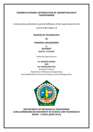
  • 19. 5 1.3 BACKGROUND 1.3.1 Absorption Introduction Comparing the absorption refrigeration cycle with the more familiar vapour compression refrigeration cycle is often an easy way to introduce it. The standard vapour compression refrigeration system is a condenser, evaporator, throttling valve, and a compressor. Fig.1 below is a schematic of the components and flow arrangements for the vapour compression cycle. In the vapour-compression refrigeration cycle, refrigerant enters the evaporator in the form of a cool, low-pressure mixture of liquid and vapour (4). Heat is transferred from the relatively warm air or water to the refrigerant, causing the liquid refrigerant to boil. The resulting vapour (1) is then pumped from the evaporator by the compressor, which increases the pressure and temperature of the refrigerant vapour. The hot, high-pressure refrigerant vapour (2) leaving the compressor enters the condenser where heat is transferred to ambient air or water at a lower temperature. Fig.1 Vapour Compression Refrigeration System Inside the condenser, the refrigerant vapor condenses into a liquid. This liquid refrigerant (3) then flows to the expansion device, which creates a pressure drop that reduces the 2 2 Win 33 1 1 4 3 3 3 Condenser Evaporator Compress or Qout Expansion Valve Qin
  • 20. 6 pressure of the refrigerant to that of the evaporator. At this low pressure, a small portion of the refrigerant boils (or flashes), cooling the remaining liquid refrigerant to the desired evaporator temperature. The cooled mixture of liquid and vapor refrigerant (4) then travels to the evaporator to repeat the cycle. Much like in the vapor compression cycle, refrigerant in the absorption cycle flows through a condenser, expansion valve, and an evaporator. However, the absorption cycle uses different refrigerants and a different method of compression than the vapor compression cycle. Absorption refrigeration systems replace the compressor with a generator and an absorber as shown in Fig.2. In absorption refrigeration systems, refrigerant enters the evaporator in the form of a cool, low-pressure mixture of liquid and vapor (4). Fig. 2 Vapour Absorption Refrigeration System Heat is transferred from the relatively warm water to the refrigerant, causing the liquid refrigerant to boil. Using an analogy of the vapour compression cycle, the absorber acts Qout 3 2 Expansion valve 4 7 Qin 6 8 5 Pump 1 Condense r Generator Absorber Evaporato r Qin Qout
  • 21. 7 like the suction side of the compressor—it draws in the refrigerant vapour (1) to mix with the absorbent. The pump acts like the compression process itself—it pushes the mixture of refrigerant and absorbent up to the high-pressure side of the system. The generator acts like the discharge of the compressor—it delivers the refrigerant vapour (2) to the rest of the system. The refrigerant vapour (2) leaving the generator enters the condenser, where heat is transferred to water at a lower temperature, causing the refrigerant vapour to condense into a liquid. This liquid refrigerant (3) then flows to the expansion device, which creates a pressure drop that reduces the pressure of the refrigerant to that of the evaporator. The resulting mixture of liquid and vapour refrigerant (4) then travels to the evaporator to repeat the cycle. 1.3.2 Similarities between Vapor Compression and Vapor Absorption Cycles The basic absorption chiller cycle is similar to the traditional vapor compression chiller cycle in that 1. Both cycles circulate refrigerant inside the chiller to transfer heat from one fluid to the other; 2. Both cycles include a device to increase the pressure of the refrigerant and an expansion device to maintain the internal pressure difference, which is critical to the overall heat transfer process; 3. Refrigerant vapor is condensed at high pressure and temperature, rejecting heat to the surroundings; 4. Refrigerant vapor is vaporized at low pressure and temperature, absorbing heat from the chilled water flow.
  • 22. 8 1.3.3 Differences between Vapor Compression and Vapor Absorption Cycles The basic absorption chiller cycle is different to the vapor compression chiller cycle in that 1. The absorption systems use heat energy in form of steam, direct fuel firing or waste heat to achieve the refrigerant effect; 2. The absorption cycle use a liquid pump, NOT a compressor to create the pressure rise between evaporator and condenser. Pumping a liquid is much easier and cheaper than compressing a gas, so the system takes less work input. However, there is a large heat input in the generator. So, the system basically replaces the work input of a vapor- compression cycle with a heat input; 3. The absorption cycle uses different refrigerants that have no associated environment hazard, ozone depletion or global warming potential (for example lithium bromide absorption system use distilled water as the refrigerant). The vapor compression refrigeration cycle generally uses a halocarbon (such as HCFC-123, HCFC-22, HFC- 134a, etc) as the refrigerant; 4. Compared to compression chillers, absorption systems contain very few moving parts, offer less noise and vibration, are compact for large capacities and require little maintenance; 5. Compared to compression chillers, the performance of absorption systems is not sensitive to load variations and does not depend very much on evaporator superheat; 6. Compared with mechanical chillers, absorption systems have a low coefficient of performance (COP = chiller load/heat input). However, absorption chillers can substantially reduce operating costs because they are powered by low-grade waste heat. The COP of absorption chiller is NOT sensitive to load variations and does not reduce significantly at part loads. From the standpoint of thermodynamics, the vapor
  • 23. 9 compression chiller is a heat pump, using mechanical energy and work, to move heat from a low to a high temperature. An absorption chiller is the equivalent of a heat engine – absorbing heat at a high temperature, rejecting heat at a lower temperature, producing work – driving a heat pump. 1.3.4 Basic Principle of Absorption System Water boils and evaporates at 212 °F (100 °C) at standard atmospheric pressure (101.3kPa). When the pressure is reduced, water boils at a lower temperature. The following table gives the total pressure in mm of mercury and the corresponding approximate water boiling temperature at different pressures. The fundamental principle of vapour absorption machine is that water boils at about 40°F at the low-pressure vacuum condition of 6.5 mm-Hg. Table: 1 Boiling point of water at different pressures The working fluid in an absorption refrigeration system is a binary solution consisting of refrigerant and absorbent. Considering Fig 3, In Fig. 3(a) two evacuated vessels are connected to each other. The left vessel contains liquid refrigerant while the right vessel contains a binary solution of absorbent/refrigerant. Absolute pressure Water boiling point (°C) 760 mm-Hg (1 atm) 100° 76 mm-Hg (0.1 atm) 46.11° 25.6 mm-Hg (0.34 atm) 26.67° 7.6 mm-Hg (0.01 atm) 7.22°
  • 24. 10 Fig.3. (a) Absorption process occurs in right vessel causing cooling effect in the other; (b) Refrigerant separation process occurs in the right vessel as a result of additional heat from outside heat source. The solution in the right vessel will absorb refrigerant vapor from the left vessel causing pressure to reduce. While the refrigerant vapor is being absorbed, the temperature of the remaining refrigerant will reduce as a result of its vaporization. This causes a refrigeration effect to occur inside the left vessel. At the same time, solution inside the right vessel becomes more dilute because of the higher content of refrigerant absorbed. This is called the “absorption process”. Normally, the absorption process is an exothermic process; therefore, it must reject heat out to the surrounding in order to maintain its absorption capability. Whenever the solution cannot continue with the absorption process because of saturation of the refrigerant, the refrigerant must be separated out from the diluted solution. Heat is normally the key for this separation process. It is applied to the right vessel in order to dry the refrigerant from the solution as shown in Fig. 3(b). The refrigerant vapor will be condensed by transferring heat to the surroundings. With these processes, the refrigeration effect can be produced by using heat energy. However, the cooling effect cannot be produced continuously as the process cannot be done simultaneously. Therefore, an absorption refrigeration cycle is a combination of these two processes refrigerant absorption and separation process. As the separation process occurs Refrigerant Solution Q H Q I Fig. 3(b) Refrigerant Solution Q I Q L Fig. 3(a)
  • 25. 11 at a higher pressure than the absorption process, a circulation pump is required to circulate the solution. Coefficient of Performance of an absorption refrigeration system is obtained from; 𝐶𝑂𝑃 = 𝑅𝑒𝑓𝑟𝑖𝑔𝑒𝑟𝑎𝑡𝑖𝑛𝑔 𝐸𝑓𝑓𝑒𝑐𝑡 𝑃𝑟𝑜𝑑𝑢𝑐𝑒𝑑 𝑖𝑛 𝐸𝑣𝑎𝑝𝑜𝑟𝑎𝑡𝑜𝑟 𝐻𝑒𝑎𝑡 𝑖𝑛𝑝𝑢𝑡 𝑖𝑛 𝐺𝑒𝑛𝑒𝑟𝑎𝑡𝑜𝑟 + 𝑃𝑢𝑚𝑝 𝑊𝑜𝑟𝑘 𝑖𝑛𝑝𝑢𝑡 The work input for the pump is negligible relative to the heat input at the generator; therefore, the pump work is often neglected for the purposes of analysis. 1.3.5 Working Fluid for Vapour Absorption Refrigeration Systems Performance of an absorption refrigeration system is critically dependent on the chemical and thermodynamic properties of the working fluid. A fundamental requirement of absorbent/refrigerant combination is that, in liquid phase, they must have a margin of miscibility within the operating temperature range of the cycle. The mixture should also be chemically stable, non-toxic, and non-explosive. In addition to these requirements, the following are desirable.  The elevation of boiling (the difference in boiling point between the pure refrigerant and the mixture at the same pressure) should be as large as possible.  Refrigerant should have high heat of vaporization and high concentration within the absorbent in order to maintain low circulation rate between the generator and the absorber per unit of cooling capacity.  Transport properties that influence heat and mass transfer, e.g., viscosity, thermal conductivity, and diffusion coefficient should be favourable.  Both refrigerant and absorbent should be non-corrosive, environmental friendly, and low-cost.
  • 26. 12 Many working fluids are suggested in literature. A survey of absorption fluids provided by Marcriss suggests that, there are some 40 refrigerant compounds and 200 absorbent compounds available. However, the most common working fluids are Water-NH3 and LiBr-water. Since the invention of an absorption refrigeration system, water-NH3 has been widely used for both cooling and heating purposes. Both NH3 (refrigerant) and water (absorbent) are highly stable for a wide range of operating temperature and pressure. NH3 has a high latent heat of vaporization, which is necessary for efficient performance of the system. It can be used for low temperature applications, as the freezing point of NH3 is - 77.73°C. Since both NH3 and water are volatility, the cycle requires a rectifier to strip away water that normally evaporates with NH3. Without a rectifier, the water would accumulate in the evaporator and offset the system performance. There are other disadvantages such as its high pressure, toxicity, and corrosive action to copper and copper alloy. However, water/NH3 is environmental friendly and low cost. The use of LiBr/water for absorption refrigeration systems began around 1930. Two outstanding features of LiBr/water are non-volatility absorbent of LiBr (the need of a rectifier is eliminated) and extremely high heat of vaporization of water (refrigerant). However, using water as a refrigerant limits the low temperature application to that above 0°C. As water is the refrigerant, the system must be operated under vacuum conditions. At high concentrations, the solution is prone to crystallization. It is also corrosive to some metal and expensive. Some additive may be added to LiBr-water as a corrosion inhibitor or to improve heat-mass transfer performance. Although LiBr-water and water-NH3 have been widely used for many years and their properties are well known, much extensive research has been carried out to investigate new working fluids. Fluorocarbon refrigerant-based working fluids have been studied. R22 and R21 have been widely suggested because of their favourable solubility with number of organic solvents. The two solvents, which have
  • 27. 13 stood out are Dimethyl Ether of Tetraethylene Glycol (DMETEG) and Dimethyl Formamide (DMF). Research on these kinds of working fluids may be obtained from the literature. A binary mixture using inorganic salt absorbent such as LiBr-water or NaOH- water may be the most successful working for an absorption refrigeration system. However, at high concentration such as at low temperature, the solution is prone to crystallization. It was found that the addition of a second salt as in a ternary mixture such as LiBr+ZnBr2-water can improve the solubility of the solution. Various ternary mixtures have been tested for using with an absorption system by various researchers. 1.3.6 Applications of Absorption Systems The main advantage of absorption systems is their ability to utilize waste heat streams that would be otherwise discarded. In terms of energy performance, motor-driven vapour compression chillers will beat absorption systems every time. Still there are specific applications where absorption systems have a substantial advantage over motor-driven vapour compression chillers. Some of those applications include: 1. For facilities that use lot of thermal energy for their processes, a large chunk of heat is usually discarded to the surrounding as waste. This waste heat can be converted to useful refrigeration by using a VAM and can be upgraded to more useful levels by using AHT system which can be further utilized for any process requirement. 2. For facilities that have a simultaneous need for heat and power (cogeneration system), absorption chillers can utilize the thermal energy to produce chilled water. 3. For facilities where the electrical supply is not robust, expensive, unreliable, or unavailable, it is easier to achieve heat input with a flame than with electricity. Absorption systems uses very little electricity compared to an electric motor driven compression systems.
  • 28. 14 4. For facilities, where the cost of electricity verses fuel oil/gas tips the scale in favour of fuel/gas. Various studies indicate that the absorption systems provide economic benefit in most geographical areas, due to the differential in the cost between gas and electric energy. 5. For facilities wanting to use a “natural refrigerant and aspiring for LEED certification (Leadership in Energy and Environmental Design) absorption systems are a good choice. Absorption devices do not use CFCs or HCFCs - the compounds known for causing Ozone depletion. 6. For facilities implementing clean development mechanism (CDM) and accumulating carbon credits, the absorption use coupled to waste heat recovery and cogeneration system help reduce problems related to greenhouse effect from CO2 emission. Vapour absorption system allows use of variable heat sources: directly using a gas burner, recovering waste heat in the form of hot water or low-pressure steam, or boiler-generated hot water or steam. 1.4 VARIOUS CONFIGURATIONS OF VAPOUR ABSORPTION SYSTEMS 1.4.1 Single-effect Absorption Refrigeration A single-effect absorption refrigeration system is the simplest and most commonly used design. Both vapour absorption refrigerator (VAR) and absorption heat pump (AHP) operates on the same cycle, where as absorption heat transformer works on reverse absorption refrigeration cycle.Fig.4 shows a single-effect system using non-volatility absorbent such as LiBr/water. In VAR and AHP system both generator and condenser are maintained at high pressure and absorber with evaporator maintained at low pressure. High temperature heat supplied to the generator is used to evaporate refrigerant out from
  • 29. 15 the solution (rejected out to the surroundings at the condenser) and is used to heat the solution from the absorber temperature (rejected out to the surroundings at the absorber). Fig. 4 Single-effect LiBr-water Absorption Refrigeration Thus, irreversibility is caused as high temperature heat of the generator is wasted out at the absorber and the condenser. In order to reduce this irreversibility, a solution heat exchange is introduced as show in Fig. 4. The heat exchanger allows the solution from the absorber to be preheated before entering the generator by using the heat from the hot solution leaving the generator. Therefore, the COP is improved as the heat input at the generator is reduced. Moreover, the size of the absorber can be reduced as less heat is rejected. Experimental studies shows that COP can be increased up to 60% when a solution heat exchanger is used. When volatility absorbent such as water-NH3 is used, the system requires an extra component called “a rectifier”, which will purify the refrigerant before entering the condenser. As the absorbent used (water) is highly volatile, it will be evaporated together with ammonia (refrigerant). Without the rectifier, this water will be condensed and accumulate inside the evaporator, causing the performance to drop. Even if the most common working fluids used are LiBr-water and water-NH3, various QC Expansion valve QE, Ref. effect QA Generator Absorber Evaporator Condenser SHX QG, High Pump
  • 30. 16 researchers have studied performance of a single-effect absorption system using other kinds of working fluids such as LiNO3-NH3, LiBr+ZnBr2-CH3OH, LiNO3+KNO3+NaNO3-water, LiCl-water, Glycerol-water etc. 1.4.2 Absorption Heat Transformer Any absorption refrigeration cycle exchanges heat with three external reservoirs; low, intermediate, and high temperature levels. When an absorption system is operated as a refrigerator or a heat pump, the driving heat is supplied from the high temperature reservoir. Refrigeration effect is produced at a low temperature level and rejects heat out at an intermediate temperature level. The difference between them is the duty. For a refrigerator, the useful heat transfer is at a low temperature. For the heat pump, the useful heat transfer is at an intermediate temperature. Normally, the surrounding is used as a low temperature reservoir for a heat pump or as an intermediate temperature reservoir for the refrigerator. Another type of absorption cycle is known as “an absorption heat transformer” or “a reverse absorption heat pump”. This system uses heat from an intermediate temperature reservoir as the driving heat (normally from industrial waste heat). The system rejects heat at a low temperature level (normally to the surroundings). The useful output is obtained at the highest temperature level. The use of an absorption heat transformer allows any waste heat to be upgraded to a higher temperature level without any other heat input except some work required circulating the working fluid. Fig. 5 shows a schematic diagram of an absorption heat transformer. This cycle has similar components as a single-effect absorption cycle. The difference is that an expansion device installed between the condenser and the evaporator is substituted by a pump. Waste heat at a relatively low temperature is supplied to the generator for refrigerant separation in the usual manner. Liquid refrigerant from the condenser is then pumped to the evaporator with elevated pressure. Absorption heat transformer absorbs
  • 31. 17 waste heat at the generator. Liquid refrigerant is pumped to the evaporator to absorb waste heat. High temperature useful heat from the absorber is heat of absorption. Fig. 5 Absorption heat transformer In the evaporator, refrigerant is vaporized by using the same low temperature waste heat used to drive the generator (absorption heat transformers are usually operated at same generator and evaporator temperatures). The vapour refrigerant is then absorbed into solution in the absorber which rejects the useful heat out at a high temperature level. Low-grade energy can be upgraded by using a heat transformer e.g. solar energy, industrial waste heat. 1.4.3 Multi-effect Absorption Refrigeration The main objective of a higher effect cycle is to increase system performance when high temperature heat source is available. By the term “multi-effect”, the cycle has to be configured in a way that heat rejected from a high-temperature stage is used as heat input in a low-temperature stage for generation of additional cooling effect in the low- temperature stage. Double-effect absorption refrigeration cycle was introduced during 1956 and 1958. Fig. 6 shows a system using LiBr-water as working pair. EV QG, Low Grade QA, Useful Pump Evaporator Absorber SHX Generator Condenser QC QE, Low Grade
  • 32. 18 Fig. 6 Double effect Absorption Refrigeration High temperature heat from an external source supplies to the first-effect generator. The vapour refrigerant generated is condensed at high pressure in the second-effect generator. The heat rejected is used to produce addition refrigerant vapour from the solution coming from the first-effect generator. This system configuration is considered as a series-flow- double-effect absorption system. A double-effect absorption system is considered as a combination of two single effect absorption systems whose COP value is COP single. For one unit of heat input from the external source, cooling effect produced from the refrigerant generated from the first-effect generator is 1×COP single. For any single-effect absorption system, it may be assumed that the heat rejected from the condenser is approximately equal to the cooling capacity obtained. Thus the heat supply to the second generator is 1×COPsingle. The cooling effect produced from the second-effect generator is (1×COP single) × COP single. Therefore, the COP of this double-effect absorption system is COP double=COP single+ (COP single)2 . According to this analysis, a double effect Generator I Evaporator Condenser Absorber HX II HX I Generator II QH QL QI QI
  • 33. 19 absorption system has a COP of 0.96 when the corresponding single-effect system has a COP of 0.6. Theoretical studies of a double-effect absorption system have been provided for various working fluids. If LiBr/water is replaced with water/NH3, maximum pressure in the first-effect generator will be extremely high. Several types of multi-effect absorption cycle have been analyzed by various researchers such as the triple effect absorption cycle and the quadruple-effect absorption cycle. However, an improvement of COP is not directly linked to the increment of number of effect. It must be noted that, when the number of effects increase, COP of each effect will not be as high as that for a single-effect system. Moreover, the higher number of effect leads to more system complexity. Therefore, the double-effect cycle is the one that is available commercially.
  • 34. 20 CHAPTER 2 LITERATURE REVIEW An extensive review of the literature has been done on different configuration of absorption system. Related to the designing of AHT fewer work is available in literature. The main idea was to have possible future direction of research. The literature review has been classified as under: 1. Vapour Absorption Refrigeration System. 2. Vapour Absorption Heat Transformer. 2.1 LITERATURE SURVEY RELATED TO VAR SYSTEM A large number of researchers have carried out research in the field of vapour absorption refrigeration using different working pairs and the most common working pairs are LiBr- H2O and NH3-H2O. V. Jain et al [1] carried out thermo - economic optimization of vapour compression - absorption cascaded refrigeration system (VCACRS) for water chilling application taking R410a and water - LiBr as refrigerants in compression and absorption section respectively. The main objective of optimization is to minimize the total annual cost of system which comprises of costs of exergy input and capital cost in monetary units. The appropriate set of decision variables (temperature of evaporator, condenser, generator, absorber, cascade condenser, degree of overlap and effectiveness of solution heat exchanger) minimizes the total annual cost of VCACRS by 11.9% with 22.4% reduction in investment cost at the base case whereas the same is reduced by 7.5% with 11.7% reduction in investment cost with reduced rate of interest and increased life span and period of operation. The cascading of compression and absorption systems becomes attractive for lower rate of interest and increase life span and operational period.
  • 35. 21 L. Garousi Farshi et al. [2] developed a computational model to study and compare the effect of the operating parameters on crystallization phenomenon in three classes (series, parallel and reverse parallel) of double effect LiBr – water absorption refrigeration system. Crystallization of LiBr as it is a salt is very common so in their study they purposed the air cooling system which is very attractive because the cooling tower and associated and maintenance cost can be avoided. A computer program has been developed using engineering equation solver (EES) software to carry out thermodynamic analysis of absorption refrigeration system. In their study they found that the double effect parallel and reverse parallel flow arrangements are superior in performance to series flow in term of crystallization risk. M. I. Karamangil et al. [3] studied the different literature on ARS and also studied the thermodynamic analysis of ARS using different refrigerant – absorbent pair and user friendly software was developed. The simulation result shows that COP of the system improve with increase in the generator and evaporator temperature where as lower condenser and absorber temperature is required. Also it was found that with the use of SHE COP increased by 66% and with the use of RHE and SRHE COP increased only by 14 and 6% respectively. So SRHE may not be considered practically significant. Alizadeh et al [4] carried out theoretical study on design and optimization of water – LiBr refrigeration cycle. They concluded that for a given refrigerating capacity higher generator temperature causes high cooling ratio with smaller heat exchange surface and low cost. There is a limiting factor for water lithium bromide cycles because of the problem of crystallization. Anand and Kumar [5] carried out availability analysis and calculation of irreversibility in system components of single and double effect series flow water lithium bromide
  • 36. 22 absorption systems. The assumed parameters for computation of results were condenser and absorber temperature equal to 87.8o C and 140.6o C for single effect and double effect systems respectively. Tyagi [6] carried out the detailed study on aqua-ammonia VAR system and plotted the coefficient of performance, mass flow rates as a function of operating parameters i.e. absorber, evaporator and generator temperatures. He showed that COP and work done are the function of evaporator, absorber, and condenser and generator temperature and also depends on the properties of binary solution. Aphornratana and Eames [7] investigated single effect water lithium bromide system using exergy analysis approach. It was shown that the irreversibility in generator was highest followed by absorber and evaporator. Bell et al [8] developed a LiBr-H20 experimental absorption cooling system driven by heat generated by solar energy. The components of the system are housed in evacuated glass cylinders to observe all the processes. They determined the thermodynamic performance of the system by applying mass and energy balance for all the components. Their work was based on the assumption that the working fluids are in equilibrium and the temperature of the working fluid leaving the generator and absorber is equal to the temperature of generator and absorber respectively. They concluded that the COP of the system depends on generator temperature and there is optimum value of generator temperature at which the COP is maximum. They also concluded that by operating the system at low condenser and absorber temperatures, a satisfactory COP is obtained at a generator temperature as low as 68o C. Horuz [9] explained the fundamental vapour absorption refrigeration system and carried out comparative study of such system based on ammonia-water and water lithium bromide working pairs. The comparison of two systems is presented in respect of COP,
  • 37. 23 cooling capacity and maximum and minimum pressures. He concluded that VAR system based on water-lithium bromide is better than ammonia-water. However, problem of crystallization lies with water-lithium bromide system. Lee and sheriff [10] carried out the second law analysis of a single effect water lithium bromide absorption refrigeration system. The effect of heat source temperature on COP and exergetic efficiency was evaluated. However, they did not analyzed effect of variation in absorber and condenser temperatures and also the effectiveness of solution heat exchanger was also not specified. Lee and sheriff carried out the second law analysis of single effect and various double effect lithium bromide water absorption chillers for chilled water temperature of 7.22o C and cooling water temperatures 29.4o C and 35o C and computed COP and exergetic efficiency. The effect of heat source temperature on COP and exergetic efficiency was investigated. In this study, the effectiveness values of solution heat exchangers considered for analysis has not been specified and their results are only valid for water cooled systems. Sozen [11] studied the effect of heat exchangers on the system performance in an ammonia water absorption refrigeration system. Thermodynamic performance of the system is analyzed and the irreversibility’s in the system components have been determined for three different cases. The COP, ECOP, circulation ratio, and non dimensional exergy loss of each component of the system is calculated. They concluded that the evaporator, absorber, generator, mixture heat exchanger and condenser show high non-dimensional exergy losses. They also concluded that using refrigerant exchanger in addition to mixture heat exchanger does not increase the system performance. De Francisco et al [12] developed and tested the prototype of a 2kW capacity water ammonia absorption system operating on solar energy for rural applications. The system also suffered from leakages in different components and need further improvements.
  • 38. 24 They concluded that the efficiency of the system is very low. The new and improved prototype has to be developed. Gomri and Hakimi [13] carried out exergy analysis of double effect lithium bromide- water absorption refrigeration system. They showed that the performance of the system increases with increasing LP generator temperature, but decreases with increasing HP generator temperature. They concluded that the highest exergy loss occurs in the absorber and in the HP generator and therefore the absorber and HP generator is the most important component of the double effect refrigeration system. Gomri [14] carried out the comparative study between single effect and double effect absorption refrigeration systems. They developed the computer program based on energy balances, thermodynamic properties to carry out thermodynamic analysis. They concluded that for each condenser and evaporator temperature, there is an optimum generator temperature where change in exergy of single effect and double effect absorption refrigeration system is minimum. Their study showed that the COP of double effect system is approximately twice the COP of single effect system but there is marginal difference between the exergetic efficiency of the system. Kaushik and Arora [15] presented the energy and exergy analysis of single effect and series flow double effect water–lithium bromide absorption system. They developed the computational model for parametric investigation. Their analysis involves the effect of generator, absorber and evaporator temperatures on the energetic and exergetic performance. They concluded that the irreversibility is highest in the absorber in both systems as compared to other systems. Zhu and Gu [16] used the first and second law of thermodynamic to analyze the performance of ammonia–sodium thiocyanate absorption system for cooling and heating applications. A mathematical model based on exergy analysis was developed. The
  • 39. 25 performance of the system is analyzed using different operating conditions. They concluded that the cooling and heating COP increases with increasing generator and evaporator temperatures but it decreases with increasing condenser and absorber temperatures. Florides et al [7] presents information on designing the heat exchangers of the LiBr– water absorption unit. Single pass, vertical tube heat exchangers have been used for the absorber and for the evaporator. The solution heat exchanger was designed as a single pass annular heat exchanger. The condenser and the generator were designed using horizontal tube heat exchangers. The calculated theoretical values are compared to experimental results derived for a small unit with a nominal capacity of 1 kW. Finally, a cost analysis for a domestic size absorber cooler is presented. 2.2 LITERATURE SURVEY RELATED TO AHT SYSTEM Large number of literature is available on absorption heat transformer performance analysis in terms of both energy and exergy, but very less literature is available regarding designing of AHT systems. Ilhami Horuz and Bener Kurt [18] AHT system using water-LiBr solution was analyzed. In this analysis it was proved that, by applying different modifications, the COP can be increased by 14.1%, the heat transfer at the absorber by 158.5% and the hot process water produced by 3.59% compared to the basic AHT system. The waste heat can be utilized by using the AHT system to generate the required energy demand. They concluded that, as the condenser temperature increases, the COPs and the absorber heat capacity decrease and when the evaporator and the generator temperatures increase, the COPs and the absorber heat capacity increases. Also, if the evaporator temperature is higher than the generator temperature, the AHT system performs better, i.e. the COP and the absorber heat capacity increase and the higher flow ratio decreases the COP and the
  • 40. 26 absorber heat capacity. It was shown that by using the AHT system, about 50% of the waste heat can be utilized and the process water hotter than the waste heat source temperature can be produced. Armando Huicochea et al [19] first and second laws of thermodynamics was used to analyze the performance of an experimental absorption heat transformer for water purification. Irreversibility, coefficients of performance (COP) and exergy coefficients of performance (ECOP) were determined as function of the mass flow of hot water supplied to the generator and as function of the overall thermal specific energy consumption (OSTEC) parameter defined in this paper. They showed that the system irreversibility increase meanwhile the coefficients of performance and the exergy coefficient of performance decrease with an increment of the mass flow of hot water supplied to the generator. K.Abrahamsson et al [20] presents a 10 kW experimental absorption heat transformer unit with self-circulation. The self-circulation was obtained by the thermo - syphon principle. The pressure difference in the unit was achieved through a difference in hydrostatic pressure. Theoretical relationships for the pressure profile within the different component of heat transformer were derived. A satisfactory stable operation with self- circulation was achieved. W. Rivera et al [21] develop mathematical models of single-stage and advanced absorption heat transformers operating with the water-lithium bromide and water-Carrol mixtures to simulate the performance of the systems coupled to a solar pond in order to increase the temperature of the useful heat produced by solar ponds. They showed that the single-stage and the double absorption heat transformer are the most promising configuration to be coupled to solar ponds. With single-stage heat transformers it is possible to increase solar pond’s temperature until 50o C with coefficients of performance
  • 41. 27 of about 0.48 and with double absorption heat transformers until 100o C with coefficients of performance of 0.33. The highest coefficients of performance were obtained with single stage heat transformers. However, the gross temperature lifts reached with these systems were the lowest. Comparing the two stage and double absorption heat transformers, it was observed that almost the same COPs and DTs are obtained with both systems at the same operating conditions. W. Rivera et al [22] analyze the performance of an experimental single stage heat transformer operating with the water/lithium bromide as single working pair and subsequently, using 1-octanol and 2-ethyl-1-hexanol as additives. The enthalpy based coefficients of performance (COP), external coefficients of performance (COPEXT), exergy-based coefficients of performance (ECOP) and the irreversibility of the equipment components were calculated for the main operating temperatures of the system. They showed that for absorber temperatures between 84o C and 88o C the highest COP, COPEXT, and ECOP are obtained with the use of the 2-ethyl-1-hexanol (400 parts per million) additive, reaching values up to 0.49, 0.40 and 0.43, respectively. The lowest coefficients of performance and highest irreversibility were obtained by using the single water/lithium bromide mixture. S. Sekar and R. Saravanan [23] vapour absorption heat transformer (VAHT) working with water–lithium bromide (LiBr) solution, coupled with a seawater distillation system of 5 kg/h distilled water capacity was tested to evaluate its performance. For this system, the COP of 0.3 to 0.38 was obtained with the maximum distillate flow rate of 4.1 kg/h and a recovery ratio of 0.17 to 0.23, under tested conditions. A maximum COP of 0.38 and a maximum temperature lift of 20°C were observed under tested conditions. They concluded that, the system performance increased at lower condenser temperatures and the distillate flow rate increases with an increase in the evaporation temperature.
  • 42. 28 Reyes et al [24] performance of AHT system with readily available, not expensive and environmentally friendly fluids like the systems H2O-CaCl2 and H2O-LiCl were studied by using a FORTRAN program. The theoretical performance of both systems in a single stage absorption heat transformer (SSHT) was derived and compared to results obtained previously for the system H2O-CaCl2 on a double absorption unit (DAHT). From modelling results, better performance of the H2O-LiCl system in a SSHT can be expected compared to that for the H2O-CaCl2 pair. However depending on every particular application and for relatively low delivery temperatures, of about 80–100o C, the use of both systems is feasible. DAHT provide lower COP values and higher temperature lifts compared to SSHT. Philip Donnellan et al [25] rigorous multi-dimensional analysis was conducted upon a triple absorption heat transformer (TAHT) using the working fluids water and lithium bromide (LiBr). A full factorial design is created which determines the most influential factors affecting the system’s coefficient of performance (COP), exergetic coefficient of performance (ECOP), flow ratio (FR) and total exergy destruction (ED). The second law performance of the system is optimized by decreasing the evaporation temperature, however this will in turn increase the system’s size and thus the evaporation temperature must be optimized by economic analysis. The generator accounts for the largest source of exergy destruction within the cycle and thus offers the greatest potential for future improvement of the system. Arzu Sencan et al [26] theoretical modelling of an absorption heat transformer for the temperature range obtained from an experimental solar pond was presented. The working fluid pair in the absorption heat transformer is aqueous ternary hydroxide fluid consisting of sodium, potassium and cesium hydroxides in the proportions 40:36:24 (NaOH: KOH: CsOH). Different methods such as linear regression (LR), pace regression (PR),
  • 43. 29 sequential minimal optimization (SMO), M5 model tree, M50 rules, decision table and back propagation neural network (BPNN) are used for modelling the absorption heat transformer. Zongchang Zhao [27] the thermodynamic performance of a new type of double absorption heat transformer (DAHT) was presented. They showed that compared with other types of DAHT this new type of DAHT has higher coefficient of performance especially when absorber temperature gets higher. The maximum coefficient of performance and the maximum gross temperature are about 0.32 and 60–100o C respectively. The maximum coefficient of performance is about 0.32. The maximum gross temperature lift is about 60–100o C which mainly depends on the corresponding condensing temperature. Djallel Zebbar et al [28] mathematical model for LiBr-H2O absorption heat transformer (AHT) operating according to the endo-irreversible cycle was presented. They concluded that for the same thermal powers and heat transfer parameters, an increase is performed of the first and second law efficiencies equal to 10% and 5.3% consecutively at the obtained optimal operating regime. They showed that the exergy analysis allows determining the local and overall irreversibility’s of the cycle, which can be used to carry out the structural analysis and determining CSBs for each element of the AHT. It was also demonstrated in this paper that they give slightly better efficiencies equal to 1.5% for the COP, 10% for the first law and 5.3% for the second law efficiency coefficients. However, these performances are obtained for the same powers and dimensions of the heat exchangers, which explain the slight change in COP. Lin Shi et al [29] the performance analysis of the single stage, the two-stage and the double absorption heat transformer with a new ejection-absorption heat transformer was presented and analyzed. They showed that this system has a simpler configuration than
  • 44. 30 the double absorption heat transformer and two-stage heat transformer. The delivered useful temperature in the ejection-absorption heat transformer is higher than a single stage heat transformer and simultaneously its system performance is raised. It was shown that delivered useful temperatures for ejection-absorption heat trans-former are higher than those for absorption heat transformers. With increasing 𝜖, the delivered useful temperatures increase. In addition, system performances of ejection-absorption heat transformers are higher than those for absorption heat transformers. Xiaodong Zhang and Dapeng Hu [30] the performance simulation of a single-stage absorption heat transformer using a new working pair composed of ionic liquids, 1-ethyl- 3-methylimidazolium di-methyl phosphate, and water (H2O+(EMIM)(DMP), was performed based on the thermodynamic properties of the new working pair and on the mass and energy balance for each component of the system. They showed that when generation, evaporation, condensing and absorption temperatures are 90o C, 90o C, 35o C and 130o C, the coefficients of performance of the single-stage absorption heat transformer using H2O+LiBr, H2O+(EMIM)(DMP) and TFE + E181 as working pairs will reach 0.494, 0.481 and 0.458 respectively. And the corresponding exergy efficiency will reach 0.64, 0.62 and 0.59, respectively. Meanwhile the available heat outputs for per unit mass of refrigerant are 2466 kJ/kg, 2344 kJ/kg and 311 kJ/kg, respectively. 2.3 LITERATURE GAP A comprehensive review of the literature on vapour absorption system is done on various aspects of energy analysis, the type of cycles analyzed, working pairs used and exergy analysis and designing of vapour absorption system. With regards to vapour absorption cycles, it is found that mostly the studies are carried out on large capacity systems and the investigation had been carried out with in a limited range of system design parameters. The literature on small vapour absorption systems is scant and very few studies have been
  • 45. 31 done on smaller systems. Literature reveals that NH3-H2O is the most suitable working fluid due to its high latent heat and excellent heat and mass transfer properties. The literature reveals that cost optimization of the system is essential to minimize the cost as this system is more capital intensive than the conventional VC and VA system. Regarding absorption heat transformer, literature review reveals that these are the systems which can be used for waste heat utilization in various sectors of industries as well as they can be incorporated with solar energy for water distillation. Also from available literature, it is concluded that a considerable amount of work is done to improve the COP of the AHT using different type of working pairs. But a little work is available on its overall size, cost and its relation with the COP of AHT. So present work aims to develop the thermodynamic model of AHT with its size and cost estimation to help the design engineer in manufacturing the system. Optimization the AHT size along with better COP is the need of the hour to reduce the initial investment. So the present work focuses on the thermo - economic optimization of AHT so that it can be a viable option for commercial purposes. It was proved that with the use of these systems about 50% of heat can be recovered. Also, the performance of AHT’s can be improved with multi-effect systems and by use of some additives. AHT’s are projected as the 21th century machines for waste heat utilization. 2.4 OBJECTIVES OF PRESENT WORK  The main objective of this study is to optimize the performance of Absorption Heat Transformer along with its size.  In the present work, a design procedure of LiBr-H2o incorporated AHT with a nominal capacity of 2kW is presented.  In the present work, a general purpose thermodynamic model of AHT is presented also; the accuracy of basis code is evaluated by comparing the results of present
  • 46. 32 study with the literature available, for this number of program codes are developed for AHT system using EES.  The energy and exergy analysis of AHT by modified Gouy –Stodola equation using first and second law of thermodynamics.  Effect of decision variables on system cost, size and performance by varying decision variables is presented.
  • 47. 33 CHAPTER 3 SYSTEM DESCRIPTION Absorption Heat Transformers (AHTs) are devices that operate in a cycle opposite to Absorption Heat Pumps (AHPs), to increase the low or moderately warm heat sources to more useful levels. Since the components of AHT system is essentially the same as the AHP, it has all the advantages that the absorption systems has. This study aims to present an alternative to the conventional heat utilization systems. By incorporating the AHT system, the waste heat can be utilized to produce hotter process water than the waste heat source. This is not the case with the conventional heat utilization systems which can only produce hot water lower than the waste heat source temperature. The necessary heat and mass transfer equations and appropriate equations describing the properties of the working fluids are specified. These equations are employed in a computer program. Information on designing the heat exchangers of the LiBr–water absorption unit is also presented. Single pass, vertical tube heat exchangers have been used for the absorber and for the evaporator. The solution heat exchanger was designed as a single pass annular heat exchanger. The condenser and the generator were designed using horizontal tube heat exchangers. 3.1 ABSORPTION HEAT TRANSFORMER A heat transformer is a device which can deliver heat at a higher temperature than the temperature of the fluid by which it is fed. The characteristics of the AHT are as follow: 1. It can transfer low-grade heat to high-grade heat with limited pump work. 2. It has no rotary device except pumps, so it is very simple in configuration, easy to operate and maintain and has a higher life expectancy. 3. It can reduce energy loss and discharge of CO2, thus reducing the greenhouse effect.
  • 48. 34 3.1.1 Basic Working Cycle of AHT The basic AHT, shown schematically in Fig. 7, operates in a cycle that is the reverse of the AHP. The AHT basically consists of an evaporator, a condenser, a generator, an absorber and a solution heat exchanger. Fig 7. Absorption Heat Transformer with Water-LiBr pair Generally, the generator and the evaporator are supplied with waste heat at the same temperature and the upgraded heat is delivered from the absorber. While part of the heat flowing into the process is removed at the ambient temperature from the condenser. The AHT cycle uses a refrigerant-absorbent solution rather than pure refrigerant as the working fluid. The absorbent acts as a secondary fluid to absorb the primary fluid, which is the refrigerant in its vapour phase. This study will concentrate on the AHT system using water-Lithium bromide (water-LiBr) solutions with water as the refrigerant. 8 7 6 9 4 3 2 EV Solution pump Pump Tout g Absorber Evaporator Heat exchanger Generator Condenser Waste heat source Tin g Tout c Tin c Tin a Tout a Tout e Tin e 1 10 5
  • 49. 35 The refrigerant-absorbent solution passing through the solution pump is referred to as a strong solution, being relatively rich in LiBr. The solution returning from the absorber to the generator contains only a little LiBr compared to the solution being pumped from the generator to the absorber and is therefore referred to as weak solution. The operating sequence of the AHT shown in Fig. 7; refrigerant vapour at state 4 is produced in the evaporator, heated by the low/medium grade heat source. The refrigerant vapour is absorbed in the refrigerant-absorbent solution that enters the absorber at a strong state 10 and leaves weak at state 5. The heat of absorption is transferred to the cooling water of the absorber and boosts its temperature. The weak solution is transferred to the generator, where some refrigerant vapour is removed from it, then returned in a strong state to the absorber. Low/medium grade energy is supplied to the generator to provide the energy for desorption from state 7 to 8. The vaporized refrigerant is condensed in the condenser then pumped to a higher pressure region where it is evaporated by the waste heat. The evaporated refrigerant is then absorbed in the absorber at a higher temperature. Thus, the AHT has the unique capability of rising the temperature of the solution above the waste heat source temperature. The performance of the AHT is improved by installing a counter flow heat exchanger between the weak and strong solutions. This solution heat exchanger increases the amount of sensible heat transported by the weak solution from the absorber to the generator. As can be seen from Fig. 8, the AHT system operates at two pressure levels: the high pressure which is the saturation pressure of the evaporator temperature and the low pressure which is the saturation pressure of the condenser temperature. In contrast to the AHP, while the evaporator and absorber run at the high pressure, the generator and condenser run at the low pressure. Fig. 8 illustrates the Pressure Temperature diagram of the AHT system.
  • 50. 36 Fig. 8 Pressure Temperature diagram of AHT As Figs. 7 and 8 present, generally the evaporator and the generator temperatures are the same, since both of them use the same waste heat source. There are three temperature levels in the AHT system; TGE, TAB and TCO, which are the generator, the absorber and the condenser temperatures respectively. 3.1.2 Function of various components of AHT Generator: The purpose of the generator is to deliver the refrigerant vapor to the rest of the system. It accomplishes this by separating the water (refrigerant) from the lithium bromide and water solution. In the generator, an intermediate-temperature energy source, typically waste heat or hot water, flows through tubes that are immersed in a dilute solution of refrigerant and absorbent. The solution absorbs heat from the waste heat or water, causing the refrigerant to boil (vaporize) and separate from the absorbent solution. As the refrigerant is boiled away, the absorbent solution becomes more concentrated. The concentrated absorbent solution or strong solution of LiBr-H2o is then pumped to the absorber and the refrigerant vapor migrates to the condenser.
  • 51. 37 Condenser: The purpose of condenser is to condense the refrigerant vapors. Inside the condenser, cooling water flows through tubes and the hot refrigerant vapor fills the surrounding space. As heat transfers from the refrigerant vapor to the water, refrigerant condenses on the tube surfaces. The condensed liquid refrigerant collects in the bottom of the condenser before traveling to the expansion device. The cooling water system is typically connected to a cooling tower. Generally, the generator and condenser are contained inside of the same shell. Evaporator: The purpose of evaporator is to supply intermediate temperature heat to the refrigerant by circulating hot water or waste heat. The evaporator contains a bundle of tubes that carry the hot water. Low pressure liquid condensate (refrigerant) is pumped to the evaporator pressure by a refrigerant pump. At this high pressure, the refrigerant absorbs heat from the circulating hot water and evaporates. The refrigerant vapors thus formed tend to increase the pressure in the vessel. This will in turn increase the boiling temperature and the desired effect will not be obtained. So, it is necessary to remove the refrigerant vapors from the vessel into the high pressure absorber. Physically, the evaporator and absorber are contained inside the same shell, allowing refrigerant vapors generated in the evaporator to migrate continuously to the absorber. Absorber: Inside the absorber, the refrigerant vapour is absorbed by the strong lithium bromide solution. As the refrigerant vapour is absorbed, it condenses from a vapour to a liquid, releasing the heat due to mixing and exothermic reactions. This heat increases the temperature inside the absorber. The absorption process creates a lower pressure within the absorber. This lower pressure, along with the absorbent’s affinity for water, induces a
  • 52. 38 continuous flow of refrigerant vapour from the evaporator. In addition, the absorption process condenses the refrigerant vapours and releases the heat removed from the evaporator by the refrigerant. The heat released from the condensation of refrigerant vapours and their absorption in the solution is removed to the hot water that is circulated through the absorber tube bundle which results in the up gradation of its temperature. As the concentrated solution absorbs more and more refrigerant; its absorption ability decreases. The weak absorbent solution is then pumped to the generator where heat is used to drive off the refrigerant. The hot refrigerant vapours created in the generator migrate to the condenser. The cooling tower water circulating through the condenser turns the refrigerant vapours to a liquid state and picks up the heat of condensation, which it rejects to the cooling tower. The liquid refrigerant returns to the evaporator and completes the cycle. Expansion Device: From the absorber, the weak solution of absorbent and refrigerant flows through an expansion device into the generator. The expansion device is used to maintain the pressure difference between the high-pressure (absorber and evaporator) and low-pressure (generator and condenser) sides of the solution circuit system by creating a liquid seal that separates the high-pressure and low pressure sides of the cycle. As the high-pressure weak solution flows through the expansion device, it causes a pressure drop which reduces its pressure to that of the generator pressure. This pressure reduction causes a small portion of the liquid refrigerant-absorbent solution to boil off, cooling the remaining solution to the desired generator temperature. The weak solution of refrigerant and absorbent is then flows into the generator.
  • 53. 39 Pump: Pump is used to circulate low pressure refrigerant and low pressure solution to high pressure evaporator and absorber respectively. Two types of pumps are used in AHT, one is refrigerant pump and another is solution pump. Pumps are the only consumers of high grade energy in absorption system. As pumps are used to circulate liquids, that’s why they consume very little work. Hence pump work is generally neglected in AHT’s analysis. 3.1.3 Efficiency of Absorption Heat Transformer (AHT) Efficiencies of AHT’s is described in terms of Coefficient of Performance (COP) like absorption refrigeration systems, and is defined as the heat supplied in the absorber, in kW, divided by the heat input in generator, evaporator and pump work in kW. COP = 𝐻𝑒𝑎𝑡 𝑠𝑢𝑝𝑝𝑙𝑖𝑒𝑑 𝑖𝑛 𝐴𝑏𝑠𝑜𝑟𝑏𝑒𝑟 ℎ𝑒𝑎𝑡 𝑠𝑢𝑝𝑝𝑙𝑖𝑒𝑑 𝑖𝑛 𝑔𝑒𝑛𝑒𝑟𝑎𝑡𝑜𝑟 + ℎ𝑒𝑎𝑡 𝑖𝑛𝑝𝑢𝑡 𝑖𝑛 𝑒𝑣𝑎𝑝𝑜𝑟𝑎𝑡𝑜𝑟 + 𝑝𝑢𝑚𝑝 𝑤𝑜𝑟𝑘 3.1.4 Key Characteristics of Lithium Bromide (LiBr) – Water Absorption System  Lithium bromide is a salt and desiccant (drying agent). The lithium ion (Li+) in the lithium bromide solution and the water molecules have a strong association, producing the absorption essential for the heat transformer to operate. Water is the refrigerant and LiBr is the absorbent;  LiBr system operates under vacuum; the vacuum pumps are needed only for short duration while starting the machine; after that, equilibrium condition is maintained by physical and chemical phenomena;  Since water is the refrigerant for the LiBr absorption system, the minimum possible chilled water temperature, at its lowest, is about 44° F; consequently, LiBr absorption chillers are used in large air-conditioning applications;  The advantage of the water-LiBr pair includes its stability, safety, and high volatility ratio.
  • 54. 40 Cautions:  At high concentrations and low temperature the solution is prone to crystallization.  The lithium bromide solution is corrosive to some metals. Corrosion inhibitors may be added to protect the metal parts and to improve heat-mass transfer performance. 3.2 PRACTICAL PROBLEMS Practical problems typical to water-lithium bromide systems are: 1. Crystallization 2. Air leakage 3. Corrosion 3.2.1 Crystallization Lithium Bromide absorbent is prone to crystallization. Crystallization is a phenomenon that causes aqueous solution of LiBr to permanently separate into salt at low cooling water temperatures. Crystallization is likely to occur when condenser pressure falls and when there is sudden drop in condenser water temperature. While reducing condenser water temperature does improve performance, it could cause a low enough temperature in the heat exchanger to crystallize the concentrate. Power failures can cause crystallization as well. A normal absorption chiller shutdown uses a dilution cycle that lowers the concentration throughout the machine. At this reduced concentration, the machine may cool to ambient temperature without crystallization. However, if power is lost when the machine is under full load and highly concentrated solution is passing through the heat exchanger, crystallization can occur. The longer the power is out, the greater the probability of crystallization. Crystallization is avoided by:
  • 55. 41 • Maintaining artificially high condensing pressures even though the temperature of the available heat sink is low; • Regulating cooling water flow rate to condenser; • By adding additives; • An air purging system is used to maintain vacuum. 3.3.2 Air Leakage Lithium Bromide absorption systems operate below atmosphere pressure. Any system pressure increase due to leakage of air into the system or the collection of non- condensable gases (NCG) causes a partial pressure that is additive to the vapour pressure of the LiBr-H2 O solution. As the pressure increases, so does the evaporator temperature. Air leakage into the machine can be controlled by: • Designing the machine with hermetic integrity and • Routinely purging the unit using a vacuum pump. 3.2.3 Corrosion of Components Lithium Bromide is corrosive to metals. Corrosion can occur inside the AHT due to the nature of the LiBr solution or on exterior components due to the heat source used to drive the system. The corrosive action of the LiBr solution increases with its temperature. In general, as the number of stages in an absorption system increases the temperature at the first generator also increases. This implies that special care must be used to combat corrosion in multiple-stage absorption systems. As a safeguard, and to have complete protection, a corrosion inhibitor is generally added to the absorbent and the alkalinity is adjusted. Alcohol, namely octyl alcohol, generally is added to the system to increase the absorption effect of the absorbent.
  • 56. 42 3.3 CAPACITY CONTROL The capacity of any absorption heat transformer system depends on the ability of the absorbent to absorb the refrigerant, which in turn depends on the concentration of the absorbent. To increase the capacity of the system, the concentration of absorbent should be increased, which would enable absorption of more refrigerant. Some of the most common methods used to change the concentration of the absorbent are: 1. Regulating the flow rate of weak solution coming into the generator through the expansion valve; 2. Controlling the temperature of heating fluid to the generator; 3. Controlling the flow of water used for condensing in the condenser, and 4. Re-concentrating the absorbent leaving the generator and entering the absorber. Method 1 does not affect the COP significantly as the required heat input reduces with reduction in weak solution flow rate, however, since this may lead to the problem of crystallization, many a time a combination of the above four methods are used in commercial systems to control the capacity. 3.4 ABSORPTION HEAT TRANSFORMER WORKING FLUIDS An absorption heat transformer requires two working fluids, a refrigerant and a sorbent solution of the refrigerant. In a water-LiBr AHT, water is the refrigerant; and water-LiBr solution, the sorbent. In the AHT cycle the water refrigerant undergoes a phase change in the condenser and evaporator; and the sorbent solution, a change in concentration in the absorber and evaporator. Water is an excellent refrigerant; it has high latent heat. Its cooling effect, however, is limited to temperatures above 0o C because of freezing. The sorbent, LiBr, is non-volatile, so a vapour phase in the absorption chiller is always H2O. The sorbent solution, water-LiBr, has a low H2O vapour pressure at the temperature of the absorber and high H2O vapour pressure at the temperature of the regenerator, facilitating
  • 57. 43 design and operation of the AHT. The advantage of the water-LiBr pair includes its stability, safety, and high volatility ratio. It has no associated environmental hazard, ozone depletion, or global warming potential. 3.5 AHT OPERATING CONDITIONS The choice of the refrigerant and absorbent solution concentration along with the designation of a hot water outlet temperature and cooling water inlet temperature determines the operating temperatures and pressures in the evaporator, absorber, regenerator, and condenser of the LiBr absorption heat transformer. • In the absorber, the hot water temperature determines the composition of the sorbent solution so that it absorbs the refrigerant vapour, as required, at the pressure determined by the evaporator. • In the condenser, the pressure is that of the generator. An elevated value is required to condense the refrigerant vapour at the temperature of the cooling water. The low operating pressure in the generator and condenser requires high equipment volume and a special means for reducing pressure loss in the refrigerant vapour flow. Preventing the leakage of air into the condenser and the generator is one of the main issues in operating an absorption heat transformer. A special purge device removes air and other non- condensable gases, and an external vacuum pump is used periodically to maintain low operating pressure. The high operating pressure in the absorber and evaporator requires the use of heavy-walled equipment and a pump to deliver the sorbent solution from the low-pressure generator to the high-pressure absorber. Crystallization, the deposition of LiBr from the sorbent solution at high concentrations and low temperatures, can block the sorbent flow and cause the heat transformer to shut down. Controls are usually necessary to prevent crystallization.
  • 58. 44 CHAPTER 4 MODELLING AND PERFORMANCE ANALYSIS Designing of AHT is necessary for doing thermo-economic optimization. For achieving this first the performance and exergy analysis of 2kW AHT system is presented. For simplified design of AHT system equation of mass and energy balance along with entropy generation equation were simulated by EES software and computer codes were developed. Heat transfer coefficients were found by different correlation used and various properties of LiBr-H2O solution were reproduced by EES. The equations used in this analysis are defined which provides basis for forming a computer code. The AHT model is the steady state set of these non linear equations which are solved by engineering equation solver. The accuracy of the basis code of input variables was estimated by comparing it with the data presented for the second model of AHT in Ilhami’s different models of AHT. The results show good accuracy in this analysis. 4.1 MODEL DEVELOPMENT An analytical model to simulate AHT was developed; its purpose is to assist in the design and dimensioning of this kind of system. In this model each component is treated as control volume with its own inputs and outputs. The performance of the cycle is described by mass balances on water and LiBr and energy balance for each component and, by overall energy balance and heat transfer equation between the internal and external streams. The exergy analysis is described by entropy generation in each component. Solution in the absorber and generator are considered to be in equilibrium with refrigerant vapour at the same temperature and pressure. The mathematical model developed is based on the following assumptions;
  • 59. 45 4.2 ASSUMPTION IN MATHEMATICAL MODELLING The following assumptions have been made in order to develop the mathematical models for the AHT analysis; (a) The refrigerant and solution are in steady state and thermodynamic equilibrium conditions at all states. (b) The solution at the generator and absorber outlets, as well as the refrigerant at the condenser and evaporator outlets are all saturated. (c) Heat losses and gains and pressure losses in various components and piping are neglected. (d) The mechanical work consumed by the pumps is considered negligible and pump is isentropic. (e) The evaporator and generator temperatures are the same. 4.3 MATHEMATICAL MODELLING Mathematical modelling include following set of governing equation for a particular system component expressed as; (i) Mass balance ∑ 𝑚 = 0; ∑ 𝑥𝑚 = 0 (4.1) Mass conservation includes the mass balance of the total mass and each material of the solution. In the above equation m is the mass flow rate and x is the mass fraction of LiBr in the solution. The mass fraction of the mixture at different points of the system is calculated using the corresponding temperature and pressure data. Also, the mass flow rates are obtained by energy balance in each component. (ii) Energy balance ∑ 𝑄 + ∑ 𝑊 + ∑ 𝑚 ℎ = 0 (4.2) The first law of Thermodynamics yields the energy balance of each component of AHT system. The energy balance equations for each component of AHT are expressed as follows;
  • 60. 46 By Considering Fig.9, shows a schematic diagram of absorption heat transformer and its various corresponding state points. For Absorber Qa + m5h5 = m4h4 + m10h10 (4.3) m5 = m10 + m4 (4.4) For Generator Qg + m7h7 = m8h8 + m1h1 (4.5) m7 = m1 + m8 (4.6) Fig. 9 Absorption Heat Transformer 9 5 6 7 10 4 3 2 1 Evaporator Condenser Pump 1 Generator Absorber SHX Pump 2 Waste Heat Source 8 14 Hot Water Water Hot Water 13 15 16 18 17 12 11 Water at desire Temperature Work given to Pump PRV V
  • 61. 47 For Evaporator Qe + m3h3 = m4h4 (4.7) For Condenser Qc + m2h2 = m1h1 (4.8) For Solution heat exchanger m5h5 − m6h6 = m10h10 − m9h9 (4.9) For Refrigerant Pump 𝑊𝑃𝑢𝑚𝑝,1 = 𝑚2∗(𝑃3−𝑃2) 𝜌2∗𝜂𝑃 (4.10) For Solution Pump 𝑊𝑃𝑢𝑚𝑝,2 = 𝑚8∗(𝑃9−𝑃8) 𝜌8∗𝜂𝑃 (4.11) The thermal efficiency or coefficient of performance of the heat transformer is obtained by; 𝐶𝑂𝑃𝐴𝐻𝑇 = 𝑄𝑎 𝑄𝑒+𝑄𝑔+𝑊𝑃𝑢𝑚𝑝,1+𝑊𝑃𝑢𝑚𝑝,2 (4.12) Second law provide the entropy generation during the cycle within the absorption heat transformer (AHT). Entropy balance equation used can be express as below: Entropy generation, 𝑆𝑔𝑒𝑛 = ∑𝑚𝑠𝑜𝑢𝑡 − ∑𝑚𝑠𝑖𝑛 − ∑ 𝑄 𝑇 ≥ 0 (4.13) By knowing the entropy generation, irreversible loss can be determined using modified Gouy – Stodola equation. 𝐼 = 𝑇𝑒𝑓𝑓 ∗ 𝑆𝑔𝑒𝑛 (4.14)
  • 62. 48 The effective temperature (𝑇𝑒𝑓𝑓) for a process is defined with the help of its real final state and the ideal isentropic final state as follow; 𝑇𝑒𝑓𝑓 = (𝑇𝑟− 𝑇) 𝑙𝑛 𝑇𝑟 𝑇 (4.15) Where 𝑇𝑟 and 𝑇 are real outlet temperature and theoretical outlet temperature after a reversible process. The exergy balance equation for each component of AHT is expressed as follow; General exergy equation, 𝑆𝑔𝑒𝑛 = ∑𝑚𝑜𝑢𝑡 ∗ ∑𝑆𝑜𝑢𝑡 − ∑𝑚𝑖𝑛 ∗ ∑𝑆𝑖𝑛 − ∑ 𝑄 𝑇 (4.16) Ig = To ∗ Sgen (4.17) 𝐼𝑚𝑔 = 𝑇𝑒𝑓𝑓 ∗ 𝑆𝑔𝑒𝑛 (4.18) Where 𝑆𝑔𝑒𝑛 is entropy generation Ig and 𝐼𝑚𝑔are irreversibility by Gouy-Stodola method and irreversibility by modified Gouy-Stodola method respectively. For Absorber, 𝑆𝑎 = 𝑚5 ∗ 𝑆5 − 𝑚8 ∗ 𝑆10 − 𝑚𝑟𝑒𝑓 ∗ 𝑆4 + 𝑚𝑒𝑓𝑎𝑏 ∗ 𝑐𝑝𝑎𝑏 ∗ ln[ 𝑇12 𝑇11 ] (4.19) 𝐼𝑔𝑎𝑏 = 𝑇𝑜 ∗ 𝑆𝑎 (4.20) 𝐼𝑚𝑔𝑎𝑏 = 𝑇𝑒𝑓𝑓 ∗ 𝑆𝑎 (4.21) For Generator,𝑆𝑔𝑒 = 𝑚𝑟𝑒𝑓 ∗ 𝑆1 − 𝑚8 ∗ 𝑆8 − 𝑚5 ∗ 𝑆7 + 𝑚𝑒𝑓𝑔𝑒 ∗ 𝑐𝑝𝑔𝑒 ∗ ln[ 𝑇14 𝑇13 ] (4.22) 𝐼𝑔𝑔𝑒 = 𝑇𝑜 ∗ 𝑆𝑔𝑒 (4.23) 𝐼𝑚𝑔𝑔𝑒 = 𝑇𝑒𝑓𝑓 ∗ 𝑆𝑔𝑒 (4.24) For Evaporator, 𝑆𝑒𝑣 = 𝑚𝑟𝑒𝑓 ∗ (𝑆4 − 𝑆3) + 𝑚𝑒𝑓𝑒𝑣 ∗ 𝑐𝑝𝑒𝑣 ∗ ln[ 𝑇18 𝑇17 ] (4.25) 𝐼𝑔𝑒𝑣 = 𝑇𝑜 ∗ 𝑆𝑒𝑣 (4.26) 𝐼𝑚𝑔𝑒𝑣 = 𝑇𝑒𝑓𝑓 ∗ 𝑆𝑒𝑣 (4.27) For Condenser, 𝑆𝑐𝑜 = 𝑚𝑟𝑒𝑓 ∗ (𝑆2 − 𝑆1) + 𝑚𝑒𝑓𝑐𝑜 ∗ 𝑐𝑝𝑐𝑜 ∗ ln[ 𝑇16 𝑇15 ] (4.28)
  • 63. 49 𝐼𝑔𝑐𝑜 = 𝑇𝑜 ∗ 𝑆𝑐𝑜 (4.29) 𝐼𝑚𝑔𝑐𝑜 = 𝑇𝑒𝑓𝑓 ∗ 𝑆𝑐𝑜 (4.30) In modelling, the physical and thermodynamic properties of the solution developed by Patek and Klomfar, which are reproduced in EES, are used in this work. 4.4 CALCULATION PROCEDURE This steady-state AHT model is a set of nonlinear algebraic equations, described in section 4.3, programmed in the Engineering Equation Solver (EES), which relate state- point conditions – pressure, temperature, composition, and flow rates, and equipment design parameters throughout the AHT. The procedure for the EES calculation is straightforward: first, the algebraic equations are entered into EES. Enough state-point conditions are entered so that the number of equations is equal to the number of the remaining, unknown state-point conditions. Reasonable estimates are entered for all these unknown conditions. The properties, such as the enthalpy and equilibrium functions, are related to the pressure, temperature, composition, and vapour quality of water/steam and sorbent solutions by equations in the EES. The EES then solves the equations by adjusting the estimates to reach a solution of the equations. The complete AHT model comprises 271 equations expressing basic engineering principles. 4.5 VALIDATION OF MATHEMATICAL MODELLING After obtaining the final model, the validation of the thermodynamic model has been performed, for checking the accuracy of model obtained. The work of Ilhami and Kurt [31] (second model of AHT was considered) has been taken to establish a benchmark case. The table 2 shows the inputs for the second model of AHT analyzed by Ilhami and Kurt [15]. The results of the present system obtained (with Ilhami inputs) in comparison with results obtained by Ilhami and Kurt [18] are displayed in table 3.
  • 64. 50 Table 2: Ilhami’s Inputs Temperature of absorber (Tab) 130o C Temperature of condenser(Tco) 25o C Temperature of generator(Tg) 73o C Temperature of evaporator(Te) 80o C Mass of refrigerant 0.2241666 kg/s Solution heat exchanger outlet temperature 120o C The results obtained for the present model are very much comparable with the results of Ilhami and Kurt. Table 3: Validation of AHT modelling Characteristics of AHT Ilhami Results [18] Present Results Heat transfer in Absorber, QAB (kW) 486.91 491.6 Heat transfer in Condenser, QCO 566.80 567.6 Heat transfer in Evaporator, QEV (kW) 558.13 569 Heat transfer in Generator, QGN (kW) 495.58 490.1 Heat transfer in Solution heat exchanger, QSHX (kW) 337.11 373 Coefficient of performance, COP 0.46 0.4642 Strong solution concentration, Xs 0.6244 0.6243 Weak solution concentration, Xw 0.5926 0.5962 Flow ratio, f 18.63 18.72 After the successful validation of the present model, it is used to analyze the performance of 2kW AHT system. In this present study of a small size AHT the generator and
  • 65. 51 evaporator are maintained at the same temperature by a single heat source as shown in Fig. 9. Some of the inputs are required to be fixed for this analysis, are described in table 4. Table 4: Fixed data in the analysis Temperature of absorber (Tab) 120o C Temperature of condenser(Tco) 40o C Temperature of generator(Tg) 80o C Temperature of evaporator(Te) 80o C Heat transfer in Absorber, Useful heat, QAB (kW) 2 Strong solution outlet temperature in SHX 110o C 4.6 FIRST LAW ANALYSIS OF ABSORPTION HEAT TRANSFORMER The performance of the system is analyzed on the basis of First law of Thermodynamics. The results obtained for a 2kW system with the inputs shown in table 4 are displayed in table 5. Table 5 : First law results for AHT Mass of refrigerant (kg/s) 0.0009739 Heat transfer in Condenser, heat rejected to surrounding, QCO 2.417 Heat transfer in Evaporator, heat supplied, QEV (kW) 2.411 Heat transfer in Generator, heat supplied, QGN (kW) 2.006 Heat transfer in Solution heat exchanger, QSHX (kW) 1.204 Coefficient of performance, COP 0.4528 Carnot COP 0.75
  • 66. 52 Strong solution concentration, X8 0.5762 Weak solution concentration, X5 0.5489 Flow ratio, f 20.14 Table 6: Various properties at different state points in the system Point Enthalpy (kJ/kg) m (kg/s) P (kPa) T (0 c) X ( % LiBr) Remark 1. 2649 0.0009739 7.381 80 0 Superheated steam 2. 167.5 0.0009739 7.381 40 0 Saturated liquid 3. 167.5 0.0009739 47.37 40 0 Liquid refrigerant 4. 2643 0.0009739 47.37 80 0 Superheated steam 5. 262.3 0.02059 47.37 120 0.5489 Weak solution 6. 203.8 0.02059 47.37 92.73 0.5489 Weak solution 7. 203.8 0.02059 7.381 92.73 0.5489 Weak solution 8. 184.7 0.01961 7.381 80 0.5762 Strong solution 9. 184.7 0.01961 47.37 80 0.5762 Strong solution 10. 246.1 0.01961 47.37 110 0.5762 Strong solution 4.7 EFFECT OF VARIOUS OPERATING PARAMETERS ON COP For the performance analysis of the present system four components of AHT i.e. absorber, generator, evaporator and condenser are selected which broadly affect the performance of the system. 4.7.1 Effect of Absorber Temperature The mass flow rate increased by 37.2% with increase in the absorber temperature because at high temperature absorption power of LiBr decreases. Graph 1 show that the Carnot
  • 67. 53 COP and COP of system are decreased by 2.5% and 25.4% respectively with increase in the absorber temperature. Absorber Temperature, Tab 116 117 118 119 120 121 122 123 124 COPaht, COPcarnot, x 5 0.3 0.4 0.5 0.6 0.7 0.8 mass flow rate of weak solution(Kg/s) 0.01 0.02 0.03 0.04 0.05 0.06 0.07 COPaht COPcarnot x5 mass flow rate of weak solution Fig 10 Effect of Absorber Temperature Generator Temperature, Tge 76 77 78 79 80 81 82 83 84 COPaht, COPcarnot, x 8 0.3 0.4 0.5 0.6 0.7 0.8 mass flow rate of weak solution(Kg/s) 0.01 0.02 0.03 0.04 0.05 0.06 COPaht COPcarnot x8 mass flow rate of weak solution Fig 11 Effect of Generator Temperature
  • 68. 54 4.7.2 Effect of Generator Temperature Carnot COP and COP of the system increases by 8% and 21% with increase in the generator temperature. Total mass of the solution decreases by 75% due to increase in the concentration of LiBr by 5% in the strong solution. Fig 11 shows the effect of generator on performance of AHT. 4.7.3 Effect of Condenser Temperature With the increase in condenser temperature, COP of system is decreased by 24%. Carnot COP is also decreased by 7.2% as condenser temperature is inversely proportional to Carnot COP and also gross temperature lift (GTL) reduces with increase in condenser temperature. Mass of external fluid in condenser is increased by 58% and the mass of refrigerant is also increased by 60% as shown in Fig.12. Condenser Temperature, Tco 36 37 38 39 40 41 42 43 44 COPaht, COP carnot 0.3 0.4 0.5 0.6 0.7 0.8 mass of external fluid(mef), (mref*100) kg/s 0.08 0.10 0.12 0.14 0.16 0.18 COPaht COPcarnot mef mref Fig 12 Effect of Condenser Temperature