SlideShare une entreprise Scribd logo
1  sur  58
Automobile Cooling System
The cooling system forms an intrinsic part of an
automobile engine. It performs multitude of
functions such as removing excess heat from
the engine, maintaining efficient temp and
allowing engine to perform its task within a short
span of time. Ideally, automobile cooling system
keeps the engine running at an optimum temp
whatever the operating conditions are.
Introduction
Temps in the combustion chamber of the
engine can reach 4,5000
F (2,5000
C), so cooling
the area around the cylinders is critical.
Automobile Cooling System consists of
components or equipment installed in vehs for
removing heat from all the moving parts so that
they can work suitably without 1.melting,
2.seizing and 3. overheating. More specifically,
automotive cooling system makes use of 1.
coolant, 2. lubricating oil and 3. fan to maintain
and regulate the temp of other parts of an
engine.
Automobile Cooling System
a. To keep the engine at its most efficient temp
at all speeds and operating conditions.
b. To take away extra heat before it damages
engine parts.
c. It also helps bring the engine up to normal
operating temp as quickly as possible
Automobile Cooling System
Over Cooling
 It results in losing some of the heat
used for expanding the gases to vaporize
the fuel.
 Gases will condense on cylinder walls.
 Thus lubrication will be affected
causing greater frictional loss.
Question: What are the results of overcooling?
Under coolingUnder cooling
Under cooling results in burning away
the lube oil film, boiling and evaporation
of cooling water which will create
additional frictional wear of engine.
boil hobe evaporate hobe , oil film burn hoye jabe , lub oil friction
wear
Types of Cooling SystemTypes of Cooling System
Basically, there are two types of automobile
cooling systems, which are widely used by the
automobiles namely:
a. Direct Cooling/Air Cooling system.
b. Indirect Air/ Liquid Cooling system
Air Cooling SystemAir Cooling System
The engine block is
covered in aluminum fins
that conduct the heat
away from the cylinder. A
powerful fan forces air
over these fins, which
cools the engine by
transferring the heat to
the air.
Air-cooling is mostly used by airplanes,
motorcycles and lawn mowers. Air cooling
system is feasible for only small vehicles and
equipment, as air-cooled engines do not operate
at consistent temp and command extensive use
of aluminum to disperse heat.
Air Cooling SystemAir Cooling System
The amount of heat dissipated to the cooling
air depends upon:
 Total surface area of the fins.
 Velocity and amount of the cooling air.
 Temp of the cylinder fins and cooling air.
 Cheaper to manufacture.
 No topping up of cooling system is
required.
 Does not freeze up and no anti-freeze is
required.
 Cylinder and cylinder head casting are
less complicated.
 Engine wt is reduced.
 Its bulk is reduced.
 Engine warms up faster.
Advantages of Air Cooling System:
Disadvantages of Air Cooling System:
 Difficult to maintain even cooling all around
the cylinder.
 Not suitable for multi cylinder engines.
 Cooling system efficiency is less than water
cooling.
 More noisy.
Water Cooling SystemWater Cooling System
The fluid circulates through pipes and
passageways in the engine. As the liquid passes
through the hot engine it absorbs heat, cooling
the engine. After the fluid leaves the engine, it
passes through a heat exchanger, or radiator,
which transfers the heat from the fluid to the air
blowing through the exchanger.
The liquid-cooling system for automobiles offers
the most positive cooling and it maintains an
optimum engine temp.
Automobile Cooling System
The pump sends the fluid into the engine block, where it
makes its way through passages in the engine around
the cylinders. Then it returns through the cylinder head
of the engine. The thermostat is located where the fluid
leaves the engine. The plumbing around the thermostat
sends the fluid back to the pump directly if the
thermostat is closed. If it is open, the fluid goes through
the radiator first and then back to the pump. There is
also a separate circuit for the heating system. This
circuit takes fluid from the cylinder head and passes it
through a heater core and then back to the pump.
Water Cooling SystemWater Cooling System
Advantages of Water Cooling
 More suitable for multi cylinder engines.
 Small amount of water is require to
absorb a large amount of heat.
 Engine temp can be control properly
due to use of thermostat.
 Water jackets reduce the engine noise.
 It is easier to install the heating system
in a car.
Disadvantages Of Water Cooling
 Water freezes and causes damage.
 Engine may run hot or get seized if there
is any loss of water .
 More expensive than air cooling..
 System is heavy and bulky.
The main Components of Water Cooling
System are as follows:
a. Radiator
b. Thermostat
c. Pump
d. Fan
e. Hose
f. Heater (Auxiliary)
Components of Water Cooling System
3. Thermostat.
Main Components of water cooling
system:
a. Water Jackets.
b. Water Pump.
c. Thermostat.
d. Radiator.
(1) Radiator pressure cap.
(2) Expansion Tank / Recovery Tank..
e. Fan.
f. Hose.
g. Heater (Auxiliary).
Water Jackets
The water jackets are open
spaces between the
cylinder walls and the
outside shell of the block
and head. Coolant from the
water pump flows first
through the block water
jackets. Then the coolant
flows up through the
cylinder head water jackets
and back to the radiator.
Water Pump
The heart of the cooling
system is the water
pump. Its job is to move
the coolant through the
cooling system. The
water pump is driven by
the crankshaft through
pulleys and a drive V
belt.
Automobile Cooling System
The inlet to the pump is located near the center
so that fluid returning from the radiator hits the
pump vanes. The pump vanes fling the fluid to
the outside of the pump, where it can enter the
engine.
The fluid leaving the pump flows first through the
engine block and cylinder head, then into the
radiator and finally back to the pump.
Water Pump
Thermostat
The thermostat is a
heat operated valve
that regulates coolant
temp. When the
engine is cold, the
thermostat closes. As
the engine warms up,
the thermostat opens.
It allows or prevent
coolant flow through
the radiator.
The thermostat's main job is to allow the engine
to heat up quickly, and then to keep the engine
at a constant temp. It does this by regulating the
amount of water that goes through the radiator.
At low temps, the outlet to the radiator is
completely blocked - all of the coolant is re-
circulated back through the engine.
Thermostat
The thermostat opens at a specific temp or
thermostat rating. Two common ratings are 850
C
and 910
C. Most thermostats begin to open at
their rated temp. They are fully open about 110
C
higher.
Once the temp of the coolant rises to between
(82 - 910
C), the thermostat starts to open,
allowing fluid to flow through the radiator. By the
time the coolant reaches 93 to 1030
C, the
thermostat is open all the way.
Thermostat
a. To block the coolant flow to the radiator.
b. To allow the coolant flow to the radiator.
c. To regulate the engine temperature.
Functions:
There are several types of automotive
thermostat. A heat sensitive wax pellet operates
most thermostats. It expands with increasing
temp to open the valve.
Types:
a. Bellows or Aneroid type
b. Wax or Hydrostatic type
Thermostat
Bellows Type Thermostat
Wax Thermostat
Components:
 Copper Loaded Wax
 Rubber Plunger
THERMOSTAT
Radiator
The radiator is basically a heat
exchanger , transferring heat from
the engine to the air passing
through it by the fan. The radiator
itself is a series of tubes and fins
that expose the coolant's heat to as
much surface area as possible. In
the radiator, coolant loss heat to
the passing air. Radiator has three
main parts as follows:
a. Inlet Tanks/ Upper Tank .
b. Radiator Core.
c. Outlet Tanks/Lower Tank
Radiator
Radiator
Radiator Pressure Cap
Radiator pr caps are
equipped with pr springs and
vents. It has a pr relief valve
and a vacuum relief valve.
Caps are normally designed
to hold the pr between 14 to
17 psi ( 96.53 and 117.21
kPa). For increasing pr one
pound the boiling point raised
about 1.80
C .
When the fluid in the cooling system heats up, it expands,
causing the pr to build up. The cap is the only place where
this pr can escape, so the setting of the spring on the cap
determines the maximum pr in the cooling system. When
the pr reaches 15 psi, the pr pushes the valve open,
allowing coolant to escape from the cooling system. This
coolant flows through the overflow tube into the bottom of
the overflow tank. This arrangement keeps air out of the
system. When the radiator cools back down, a vacuum is
created in the cooling system that pulls open another
spring loaded valve, sucking water back in from the bottom
of the overflow tank to replace the water that was expelled.
Radiator Pressure Cap
Function of radiator pr cap
♦ The cap allows for increase in pr in the
radiator, which raises the boiling point of the
coolant. The radiator cap actually increases the
boiling point of the coolant by about 450
F (250
C).
♦ Sealing reduces coolant losses from
evaporation.
♦ When the pr goes too high, it raises the pr
relief valve. Excess pr and coolant then escape
into the expansion tank.
♦ It protects the system from developing a
vacuum that could collapse the radiator. When
the engine is shut off and begins to cool, the
coolant contracts and a vacuum develops in the
cooling system. This pulls open the vacuum
valve. Coolant from the expansion tank then
flows back into the cooling system.
Function of radiator pr cap
Expansion Tank
Expansion tank is designed/used to catch and hold any
coolant that passes through the pr cap when the engine
is hot. It is partially filled with coolant and connected by
an overflow tube to the radiator.
As the engine warms up, the coolant expands. This
eventually causes the pr cap release. The coolant
passes to an expansion tank.
When the engine is shut down, the coolant begins to
shrink. Eventually , the vacuum spring inside the pr cap
opens and the coolant in the expansion tank is drawn
back into the radiator.
Expansion Tank
Expansion Tank
Engine Fan
The radiator sometimes
needs additional airflow
through it to prevent the
engine from
overheating. An engine
fan pulls the additional
air through the radiator.
The fan may be either a
mechanical fan or an
electric fan.
Mechanical Fan
Engines mounted
longitudinally in rear-
drive vehicles usually
have a mechanical fan
that mounts to the
water-pump shat.
Electric Fan
Transverse engines in front-drive vehicles
usually have an electric fan. An electric motor
turns the blades. A thermostat switch turns on
the fan only when needed.
Advantage of an Electric Fan
♦ An electric fan drains less power from the
engine.
♦ Creates less noise than a mechanical fan.
♦ There is no fan belt to inspect, adjust or
replace
Hoses
Function:
 To carry hot and cold streams of liquid to the
radiator and the engine channel.
 The interconnecting hoses from radiator to
engine and from engine to cabin heater and
back again are very special.
Construction:
 Radiator to engine hoses -metal coil
reinforced hoses.
 The bottom hose.
 Hose clamps.
Hoses
Heater
Functions:
 Act as a secondary
cooling system
 It is not an electric
heater
COOLANT
Coolant is actually a mixture of water and
ethylene glycol-based antifreeze. Water alone
has a boiling point of 1000
C at sea level.
A mixture of 67% antifreeze and 33% water will
raise the boiling point of the mixture to 1130
C
and lower the freezing point to – 690
C.
If the % is lower than 44%, engine parts may be
eroded by cavitations and cooling system
components may be severely damaged by
corrosion.
COOLANT
Recommended mixture is a 50/50 solution of
water and antifreeze. The anti freeze
concentration minimum of 44% all year and in
all climates.
If the % is 100%, engine will be extremely
heated
Coolant performs three basic jobs:
♦ It lowers the freezing point of the engine
coolant to −370
C.
♦ It raises the boiling point of the engine
coolant to 1080
C.
♦ It helps protect the cooling system metals
from deposits and corrosion.
ENGINE OVERHEATING
POSSIBLE CAUSES
Low coolant level
Loose fan belt.
Pressure cap defective.
Radiator obstructed.
Fan drive clutch defective
Inadequate coolant flow
REMEDY
Fill as require.
Adjust.
Replace.
Repair/clean
Replace/Repair.
Check pump.

Contenu connexe

Tendances

INTERNAL COMBUSTION ENGINES PPT
INTERNAL COMBUSTION ENGINES PPT INTERNAL COMBUSTION ENGINES PPT
INTERNAL COMBUSTION ENGINES PPT AKASH1001
 
Chapter 2 cooling system
Chapter 2   cooling systemChapter 2   cooling system
Chapter 2 cooling systemHafizkamaruddin
 
Air Injection and Solid Injection System
Air Injection and Solid Injection SystemAir Injection and Solid Injection System
Air Injection and Solid Injection SystemParthivpal17
 
Fuel Injection Systems
Fuel Injection SystemsFuel Injection Systems
Fuel Injection SystemsRajat Seth
 
Cooling system in automotive
Cooling system in automotiveCooling system in automotive
Cooling system in automotiveManojitBiswas4
 
Lubrication system for an automobile
Lubrication system for an automobile Lubrication system for an automobile
Lubrication system for an automobile sgrsoni45
 
Cooling system ppt
Cooling system pptCooling system ppt
Cooling system pptasu21
 
Engine service and overshuling
Engine service and overshulingEngine service and overshuling
Engine service and overshulingShahid Akram
 
Diesel fuel injection system
Diesel fuel injection systemDiesel fuel injection system
Diesel fuel injection systemINTAKHAB KHAN
 
Internal combustion engine
Internal combustion engineInternal combustion engine
Internal combustion engineGaurav Bhati
 
Common rail diesel fuel systems
Common rail diesel fuel systemsCommon rail diesel fuel systems
Common rail diesel fuel systemsamged radhi
 
Cooling system in i.c engine
Cooling system in i.c engineCooling system in i.c engine
Cooling system in i.c enginefadwala07
 
Brakes and its types
Brakes and its typesBrakes and its types
Brakes and its typesOm Patil
 
Complete guide to Internal Combustion engines (IC engines)
Complete guide to Internal Combustion engines (IC engines)Complete guide to Internal Combustion engines (IC engines)
Complete guide to Internal Combustion engines (IC engines)Syed Yaseen
 
Cooling System - IC Engines : Unit-III
Cooling System - IC Engines : Unit-IIICooling System - IC Engines : Unit-III
Cooling System - IC Engines : Unit-IIIS.Vijaya Bhaskar
 
Lubrication System - IC Engine - Unit-III
Lubrication System - IC Engine - Unit-IIILubrication System - IC Engine - Unit-III
Lubrication System - IC Engine - Unit-IIIS.Vijaya Bhaskar
 

Tendances (20)

Cooling system
Cooling systemCooling system
Cooling system
 
INTERNAL COMBUSTION ENGINES PPT
INTERNAL COMBUSTION ENGINES PPT INTERNAL COMBUSTION ENGINES PPT
INTERNAL COMBUSTION ENGINES PPT
 
Chapter 2 cooling system
Chapter 2   cooling systemChapter 2   cooling system
Chapter 2 cooling system
 
Air Injection and Solid Injection System
Air Injection and Solid Injection SystemAir Injection and Solid Injection System
Air Injection and Solid Injection System
 
Fuel Injection Systems
Fuel Injection SystemsFuel Injection Systems
Fuel Injection Systems
 
Cooling system in automotive
Cooling system in automotiveCooling system in automotive
Cooling system in automotive
 
Lubrication system for an automobile
Lubrication system for an automobile Lubrication system for an automobile
Lubrication system for an automobile
 
Cooling system ppt
Cooling system pptCooling system ppt
Cooling system ppt
 
Engine Cooling system
Engine Cooling systemEngine Cooling system
Engine Cooling system
 
Braking systems
Braking systemsBraking systems
Braking systems
 
Engine service and overshuling
Engine service and overshulingEngine service and overshuling
Engine service and overshuling
 
Diesel fuel injection system
Diesel fuel injection systemDiesel fuel injection system
Diesel fuel injection system
 
engine auxiliary systems
 engine auxiliary systems engine auxiliary systems
engine auxiliary systems
 
Internal combustion engine
Internal combustion engineInternal combustion engine
Internal combustion engine
 
Common rail diesel fuel systems
Common rail diesel fuel systemsCommon rail diesel fuel systems
Common rail diesel fuel systems
 
Cooling system in i.c engine
Cooling system in i.c engineCooling system in i.c engine
Cooling system in i.c engine
 
Brakes and its types
Brakes and its typesBrakes and its types
Brakes and its types
 
Complete guide to Internal Combustion engines (IC engines)
Complete guide to Internal Combustion engines (IC engines)Complete guide to Internal Combustion engines (IC engines)
Complete guide to Internal Combustion engines (IC engines)
 
Cooling System - IC Engines : Unit-III
Cooling System - IC Engines : Unit-IIICooling System - IC Engines : Unit-III
Cooling System - IC Engines : Unit-III
 
Lubrication System - IC Engine - Unit-III
Lubrication System - IC Engine - Unit-IIILubrication System - IC Engine - Unit-III
Lubrication System - IC Engine - Unit-III
 

Similaire à Automotive cooling system

IC Engines lubrication & cooling methods
IC Engines lubrication & cooling methodsIC Engines lubrication & cooling methods
IC Engines lubrication & cooling methodsvinodh32
 
Automotive cooling system
Automotive cooling systemAutomotive cooling system
Automotive cooling systemBhaskar Paul
 
Report of Engine Cooling & Exhaust System
Report of Engine Cooling & Exhaust SystemReport of Engine Cooling & Exhaust System
Report of Engine Cooling & Exhaust SystemMal Mai
 
2 Cooling System Theory.ppt
2 Cooling System Theory.ppt2 Cooling System Theory.ppt
2 Cooling System Theory.pptAbhishekChavan77
 
Cooling System.pptx
Cooling System.pptxCooling System.pptx
Cooling System.pptxNajmulMithun
 
Engine Cooling System (ppt).pptx
Engine Cooling System (ppt).pptxEngine Cooling System (ppt).pptx
Engine Cooling System (ppt).pptxRanit Sarkar
 
SYSTEMS OF IC ENGINE- Cooling System.pptx
SYSTEMS OF IC ENGINE- Cooling System.pptxSYSTEMS OF IC ENGINE- Cooling System.pptx
SYSTEMS OF IC ENGINE- Cooling System.pptxAjay Singh Lodhi
 
Car Air condition cycle.ppt
Car Air condition cycle.pptCar Air condition cycle.ppt
Car Air condition cycle.pptHaroonMurshed
 
Chapter 20
Chapter 20Chapter 20
Chapter 20mcfalltj
 
Chapter 20
Chapter 20Chapter 20
Chapter 20mcfalltj
 
Cooling system in cars engines
Cooling system in cars engines Cooling system in cars engines
Cooling system in cars engines MahdiKarim6
 

Similaire à Automotive cooling system (20)

Mohammad afazal ppt
Mohammad afazal pptMohammad afazal ppt
Mohammad afazal ppt
 
IC Engines lubrication & cooling methods
IC Engines lubrication & cooling methodsIC Engines lubrication & cooling methods
IC Engines lubrication & cooling methods
 
Automotive cooling system
Automotive cooling systemAutomotive cooling system
Automotive cooling system
 
Report of Engine Cooling & Exhaust System
Report of Engine Cooling & Exhaust SystemReport of Engine Cooling & Exhaust System
Report of Engine Cooling & Exhaust System
 
Cooling systems
Cooling systemsCooling systems
Cooling systems
 
2 Cooling System Theory.ppt
2 Cooling System Theory.ppt2 Cooling System Theory.ppt
2 Cooling System Theory.ppt
 
Cooling system
Cooling systemCooling system
Cooling system
 
ppe cooling system.pptx
ppe cooling system.pptxppe cooling system.pptx
ppe cooling system.pptx
 
Methods of Cooling.pptx
Methods of Cooling.pptxMethods of Cooling.pptx
Methods of Cooling.pptx
 
Application
ApplicationApplication
Application
 
Cooling System.pptx
Cooling System.pptxCooling System.pptx
Cooling System.pptx
 
Engine Cooling System (ppt).pptx
Engine Cooling System (ppt).pptxEngine Cooling System (ppt).pptx
Engine Cooling System (ppt).pptx
 
Theory 3.pptx
Theory 3.pptxTheory 3.pptx
Theory 3.pptx
 
Ch04
Ch04Ch04
Ch04
 
SYSTEMS OF IC ENGINE- Cooling System.pptx
SYSTEMS OF IC ENGINE- Cooling System.pptxSYSTEMS OF IC ENGINE- Cooling System.pptx
SYSTEMS OF IC ENGINE- Cooling System.pptx
 
Car Air condition cycle.ppt
Car Air condition cycle.pptCar Air condition cycle.ppt
Car Air condition cycle.ppt
 
Chapter 20
Chapter 20Chapter 20
Chapter 20
 
Chapter 20
Chapter 20Chapter 20
Chapter 20
 
Automobile
AutomobileAutomobile
Automobile
 
Cooling system in cars engines
Cooling system in cars engines Cooling system in cars engines
Cooling system in cars engines
 

Plus de Md. Imtiaz Pathan

Plus de Md. Imtiaz Pathan (8)

Fibre mechanical engineering 2016*
Fibre mechanical engineering 2016*Fibre mechanical engineering 2016*
Fibre mechanical engineering 2016*
 
Glass and everything
Glass and everythingGlass and everything
Glass and everything
 
Socialization (sociology)
Socialization (sociology)Socialization (sociology)
Socialization (sociology)
 
Culture theory
Culture theoryCulture theory
Culture theory
 
Social stratification systems
Social stratification systems Social stratification systems
Social stratification systems
 
Eece 259 dc motor
Eece 259 dc motorEece 259 dc motor
Eece 259 dc motor
 
Eece 259 dc generator
Eece 259 dc generatorEece 259 dc generator
Eece 259 dc generator
 
Phonetics
Phonetics Phonetics
Phonetics
 

Dernier

Architect Hassan Khalil Portfolio for 2024
Architect Hassan Khalil Portfolio for 2024Architect Hassan Khalil Portfolio for 2024
Architect Hassan Khalil Portfolio for 2024hassan khalil
 
US Department of Education FAFSA Week of Action
US Department of Education FAFSA Week of ActionUS Department of Education FAFSA Week of Action
US Department of Education FAFSA Week of ActionMebane Rash
 
Software and Systems Engineering Standards: Verification and Validation of Sy...
Software and Systems Engineering Standards: Verification and Validation of Sy...Software and Systems Engineering Standards: Verification and Validation of Sy...
Software and Systems Engineering Standards: Verification and Validation of Sy...VICTOR MAESTRE RAMIREZ
 
Electronically Controlled suspensions system .pdf
Electronically Controlled suspensions system .pdfElectronically Controlled suspensions system .pdf
Electronically Controlled suspensions system .pdfme23b1001
 
TechTAC® CFD Report Summary: A Comparison of Two Types of Tubing Anchor Catchers
TechTAC® CFD Report Summary: A Comparison of Two Types of Tubing Anchor CatchersTechTAC® CFD Report Summary: A Comparison of Two Types of Tubing Anchor Catchers
TechTAC® CFD Report Summary: A Comparison of Two Types of Tubing Anchor Catcherssdickerson1
 
lifi-technology with integration of IOT.pptx
lifi-technology with integration of IOT.pptxlifi-technology with integration of IOT.pptx
lifi-technology with integration of IOT.pptxsomshekarkn64
 
Vishratwadi & Ghorpadi Bridge Tender documents
Vishratwadi & Ghorpadi Bridge Tender documentsVishratwadi & Ghorpadi Bridge Tender documents
Vishratwadi & Ghorpadi Bridge Tender documentsSachinPawar510423
 
Concrete Mix Design - IS 10262-2019 - .pptx
Concrete Mix Design - IS 10262-2019 - .pptxConcrete Mix Design - IS 10262-2019 - .pptx
Concrete Mix Design - IS 10262-2019 - .pptxKartikeyaDwivedi3
 
Piping Basic stress analysis by engineering
Piping Basic stress analysis by engineeringPiping Basic stress analysis by engineering
Piping Basic stress analysis by engineeringJuanCarlosMorales19600
 
Call Girls Narol 7397865700 Independent Call Girls
Call Girls Narol 7397865700 Independent Call GirlsCall Girls Narol 7397865700 Independent Call Girls
Call Girls Narol 7397865700 Independent Call Girlsssuser7cb4ff
 
Why does (not) Kafka need fsync: Eliminating tail latency spikes caused by fsync
Why does (not) Kafka need fsync: Eliminating tail latency spikes caused by fsyncWhy does (not) Kafka need fsync: Eliminating tail latency spikes caused by fsync
Why does (not) Kafka need fsync: Eliminating tail latency spikes caused by fsyncssuser2ae721
 
UNIT III ANALOG ELECTRONICS (BASIC ELECTRONICS)
UNIT III ANALOG ELECTRONICS (BASIC ELECTRONICS)UNIT III ANALOG ELECTRONICS (BASIC ELECTRONICS)
UNIT III ANALOG ELECTRONICS (BASIC ELECTRONICS)Dr SOUNDIRARAJ N
 
Instrumentation, measurement and control of bio process parameters ( Temperat...
Instrumentation, measurement and control of bio process parameters ( Temperat...Instrumentation, measurement and control of bio process parameters ( Temperat...
Instrumentation, measurement and control of bio process parameters ( Temperat...121011101441
 
Arduino_CSE ece ppt for working and principal of arduino.ppt
Arduino_CSE ece ppt for working and principal of arduino.pptArduino_CSE ece ppt for working and principal of arduino.ppt
Arduino_CSE ece ppt for working and principal of arduino.pptSAURABHKUMAR892774
 
CCS355 Neural Network & Deep Learning Unit II Notes with Question bank .pdf
CCS355 Neural Network & Deep Learning Unit II Notes with Question bank .pdfCCS355 Neural Network & Deep Learning Unit II Notes with Question bank .pdf
CCS355 Neural Network & Deep Learning Unit II Notes with Question bank .pdfAsst.prof M.Gokilavani
 
8251 universal synchronous asynchronous receiver transmitter
8251 universal synchronous asynchronous receiver transmitter8251 universal synchronous asynchronous receiver transmitter
8251 universal synchronous asynchronous receiver transmitterShivangiSharma879191
 

Dernier (20)

Architect Hassan Khalil Portfolio for 2024
Architect Hassan Khalil Portfolio for 2024Architect Hassan Khalil Portfolio for 2024
Architect Hassan Khalil Portfolio for 2024
 
Exploring_Network_Security_with_JA3_by_Rakesh Seal.pptx
Exploring_Network_Security_with_JA3_by_Rakesh Seal.pptxExploring_Network_Security_with_JA3_by_Rakesh Seal.pptx
Exploring_Network_Security_with_JA3_by_Rakesh Seal.pptx
 
POWER SYSTEMS-1 Complete notes examples
POWER SYSTEMS-1 Complete notes  examplesPOWER SYSTEMS-1 Complete notes  examples
POWER SYSTEMS-1 Complete notes examples
 
US Department of Education FAFSA Week of Action
US Department of Education FAFSA Week of ActionUS Department of Education FAFSA Week of Action
US Department of Education FAFSA Week of Action
 
Software and Systems Engineering Standards: Verification and Validation of Sy...
Software and Systems Engineering Standards: Verification and Validation of Sy...Software and Systems Engineering Standards: Verification and Validation of Sy...
Software and Systems Engineering Standards: Verification and Validation of Sy...
 
Electronically Controlled suspensions system .pdf
Electronically Controlled suspensions system .pdfElectronically Controlled suspensions system .pdf
Electronically Controlled suspensions system .pdf
 
TechTAC® CFD Report Summary: A Comparison of Two Types of Tubing Anchor Catchers
TechTAC® CFD Report Summary: A Comparison of Two Types of Tubing Anchor CatchersTechTAC® CFD Report Summary: A Comparison of Two Types of Tubing Anchor Catchers
TechTAC® CFD Report Summary: A Comparison of Two Types of Tubing Anchor Catchers
 
lifi-technology with integration of IOT.pptx
lifi-technology with integration of IOT.pptxlifi-technology with integration of IOT.pptx
lifi-technology with integration of IOT.pptx
 
Vishratwadi & Ghorpadi Bridge Tender documents
Vishratwadi & Ghorpadi Bridge Tender documentsVishratwadi & Ghorpadi Bridge Tender documents
Vishratwadi & Ghorpadi Bridge Tender documents
 
Concrete Mix Design - IS 10262-2019 - .pptx
Concrete Mix Design - IS 10262-2019 - .pptxConcrete Mix Design - IS 10262-2019 - .pptx
Concrete Mix Design - IS 10262-2019 - .pptx
 
Piping Basic stress analysis by engineering
Piping Basic stress analysis by engineeringPiping Basic stress analysis by engineering
Piping Basic stress analysis by engineering
 
Call Girls Narol 7397865700 Independent Call Girls
Call Girls Narol 7397865700 Independent Call GirlsCall Girls Narol 7397865700 Independent Call Girls
Call Girls Narol 7397865700 Independent Call Girls
 
Why does (not) Kafka need fsync: Eliminating tail latency spikes caused by fsync
Why does (not) Kafka need fsync: Eliminating tail latency spikes caused by fsyncWhy does (not) Kafka need fsync: Eliminating tail latency spikes caused by fsync
Why does (not) Kafka need fsync: Eliminating tail latency spikes caused by fsync
 
UNIT III ANALOG ELECTRONICS (BASIC ELECTRONICS)
UNIT III ANALOG ELECTRONICS (BASIC ELECTRONICS)UNIT III ANALOG ELECTRONICS (BASIC ELECTRONICS)
UNIT III ANALOG ELECTRONICS (BASIC ELECTRONICS)
 
Instrumentation, measurement and control of bio process parameters ( Temperat...
Instrumentation, measurement and control of bio process parameters ( Temperat...Instrumentation, measurement and control of bio process parameters ( Temperat...
Instrumentation, measurement and control of bio process parameters ( Temperat...
 
Arduino_CSE ece ppt for working and principal of arduino.ppt
Arduino_CSE ece ppt for working and principal of arduino.pptArduino_CSE ece ppt for working and principal of arduino.ppt
Arduino_CSE ece ppt for working and principal of arduino.ppt
 
CCS355 Neural Network & Deep Learning Unit II Notes with Question bank .pdf
CCS355 Neural Network & Deep Learning Unit II Notes with Question bank .pdfCCS355 Neural Network & Deep Learning Unit II Notes with Question bank .pdf
CCS355 Neural Network & Deep Learning Unit II Notes with Question bank .pdf
 
Design and analysis of solar grass cutter.pdf
Design and analysis of solar grass cutter.pdfDesign and analysis of solar grass cutter.pdf
Design and analysis of solar grass cutter.pdf
 
9953056974 Call Girls In South Ex, Escorts (Delhi) NCR.pdf
9953056974 Call Girls In South Ex, Escorts (Delhi) NCR.pdf9953056974 Call Girls In South Ex, Escorts (Delhi) NCR.pdf
9953056974 Call Girls In South Ex, Escorts (Delhi) NCR.pdf
 
8251 universal synchronous asynchronous receiver transmitter
8251 universal synchronous asynchronous receiver transmitter8251 universal synchronous asynchronous receiver transmitter
8251 universal synchronous asynchronous receiver transmitter
 

Automotive cooling system

  • 2. The cooling system forms an intrinsic part of an automobile engine. It performs multitude of functions such as removing excess heat from the engine, maintaining efficient temp and allowing engine to perform its task within a short span of time. Ideally, automobile cooling system keeps the engine running at an optimum temp whatever the operating conditions are. Introduction Temps in the combustion chamber of the engine can reach 4,5000 F (2,5000 C), so cooling the area around the cylinders is critical.
  • 3. Automobile Cooling System consists of components or equipment installed in vehs for removing heat from all the moving parts so that they can work suitably without 1.melting, 2.seizing and 3. overheating. More specifically, automotive cooling system makes use of 1. coolant, 2. lubricating oil and 3. fan to maintain and regulate the temp of other parts of an engine. Automobile Cooling System
  • 4. a. To keep the engine at its most efficient temp at all speeds and operating conditions. b. To take away extra heat before it damages engine parts. c. It also helps bring the engine up to normal operating temp as quickly as possible
  • 7. Over Cooling  It results in losing some of the heat used for expanding the gases to vaporize the fuel.  Gases will condense on cylinder walls.  Thus lubrication will be affected causing greater frictional loss. Question: What are the results of overcooling?
  • 8. Under coolingUnder cooling Under cooling results in burning away the lube oil film, boiling and evaporation of cooling water which will create additional frictional wear of engine. boil hobe evaporate hobe , oil film burn hoye jabe , lub oil friction wear
  • 9. Types of Cooling SystemTypes of Cooling System Basically, there are two types of automobile cooling systems, which are widely used by the automobiles namely: a. Direct Cooling/Air Cooling system. b. Indirect Air/ Liquid Cooling system
  • 10. Air Cooling SystemAir Cooling System The engine block is covered in aluminum fins that conduct the heat away from the cylinder. A powerful fan forces air over these fins, which cools the engine by transferring the heat to the air.
  • 11. Air-cooling is mostly used by airplanes, motorcycles and lawn mowers. Air cooling system is feasible for only small vehicles and equipment, as air-cooled engines do not operate at consistent temp and command extensive use of aluminum to disperse heat. Air Cooling SystemAir Cooling System
  • 12. The amount of heat dissipated to the cooling air depends upon:  Total surface area of the fins.  Velocity and amount of the cooling air.  Temp of the cylinder fins and cooling air.
  • 13.  Cheaper to manufacture.  No topping up of cooling system is required.  Does not freeze up and no anti-freeze is required.  Cylinder and cylinder head casting are less complicated.  Engine wt is reduced.  Its bulk is reduced.  Engine warms up faster. Advantages of Air Cooling System:
  • 14. Disadvantages of Air Cooling System:  Difficult to maintain even cooling all around the cylinder.  Not suitable for multi cylinder engines.  Cooling system efficiency is less than water cooling.  More noisy.
  • 15. Water Cooling SystemWater Cooling System
  • 16. Water Cooling SystemWater Cooling System
  • 17. Water Cooling SystemWater Cooling System The fluid circulates through pipes and passageways in the engine. As the liquid passes through the hot engine it absorbs heat, cooling the engine. After the fluid leaves the engine, it passes through a heat exchanger, or radiator, which transfers the heat from the fluid to the air blowing through the exchanger. The liquid-cooling system for automobiles offers the most positive cooling and it maintains an optimum engine temp.
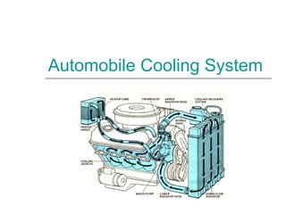
  • 19. The pump sends the fluid into the engine block, where it makes its way through passages in the engine around the cylinders. Then it returns through the cylinder head of the engine. The thermostat is located where the fluid leaves the engine. The plumbing around the thermostat sends the fluid back to the pump directly if the thermostat is closed. If it is open, the fluid goes through the radiator first and then back to the pump. There is also a separate circuit for the heating system. This circuit takes fluid from the cylinder head and passes it through a heater core and then back to the pump. Water Cooling SystemWater Cooling System
  • 20. Advantages of Water Cooling  More suitable for multi cylinder engines.  Small amount of water is require to absorb a large amount of heat.  Engine temp can be control properly due to use of thermostat.  Water jackets reduce the engine noise.  It is easier to install the heating system in a car.
  • 21. Disadvantages Of Water Cooling  Water freezes and causes damage.  Engine may run hot or get seized if there is any loss of water .  More expensive than air cooling..  System is heavy and bulky.
  • 22. The main Components of Water Cooling System are as follows: a. Radiator b. Thermostat c. Pump d. Fan e. Hose f. Heater (Auxiliary) Components of Water Cooling System
  • 23. 3. Thermostat. Main Components of water cooling system: a. Water Jackets. b. Water Pump. c. Thermostat. d. Radiator. (1) Radiator pressure cap. (2) Expansion Tank / Recovery Tank.. e. Fan. f. Hose. g. Heater (Auxiliary).
  • 24. Water Jackets The water jackets are open spaces between the cylinder walls and the outside shell of the block and head. Coolant from the water pump flows first through the block water jackets. Then the coolant flows up through the cylinder head water jackets and back to the radiator.
  • 25. Water Pump The heart of the cooling system is the water pump. Its job is to move the coolant through the cooling system. The water pump is driven by the crankshaft through pulleys and a drive V belt.
  • 27. The inlet to the pump is located near the center so that fluid returning from the radiator hits the pump vanes. The pump vanes fling the fluid to the outside of the pump, where it can enter the engine. The fluid leaving the pump flows first through the engine block and cylinder head, then into the radiator and finally back to the pump. Water Pump
  • 28. Thermostat The thermostat is a heat operated valve that regulates coolant temp. When the engine is cold, the thermostat closes. As the engine warms up, the thermostat opens. It allows or prevent coolant flow through the radiator.
  • 29.
  • 30. The thermostat's main job is to allow the engine to heat up quickly, and then to keep the engine at a constant temp. It does this by regulating the amount of water that goes through the radiator. At low temps, the outlet to the radiator is completely blocked - all of the coolant is re- circulated back through the engine. Thermostat
  • 31. The thermostat opens at a specific temp or thermostat rating. Two common ratings are 850 C and 910 C. Most thermostats begin to open at their rated temp. They are fully open about 110 C higher. Once the temp of the coolant rises to between (82 - 910 C), the thermostat starts to open, allowing fluid to flow through the radiator. By the time the coolant reaches 93 to 1030 C, the thermostat is open all the way. Thermostat
  • 32. a. To block the coolant flow to the radiator. b. To allow the coolant flow to the radiator. c. To regulate the engine temperature. Functions:
  • 33. There are several types of automotive thermostat. A heat sensitive wax pellet operates most thermostats. It expands with increasing temp to open the valve. Types: a. Bellows or Aneroid type b. Wax or Hydrostatic type Thermostat
  • 35. Wax Thermostat Components:  Copper Loaded Wax  Rubber Plunger
  • 37. Radiator The radiator is basically a heat exchanger , transferring heat from the engine to the air passing through it by the fan. The radiator itself is a series of tubes and fins that expose the coolant's heat to as much surface area as possible. In the radiator, coolant loss heat to the passing air. Radiator has three main parts as follows:
  • 38. a. Inlet Tanks/ Upper Tank . b. Radiator Core. c. Outlet Tanks/Lower Tank Radiator
  • 40. Radiator Pressure Cap Radiator pr caps are equipped with pr springs and vents. It has a pr relief valve and a vacuum relief valve. Caps are normally designed to hold the pr between 14 to 17 psi ( 96.53 and 117.21 kPa). For increasing pr one pound the boiling point raised about 1.80 C .
  • 41. When the fluid in the cooling system heats up, it expands, causing the pr to build up. The cap is the only place where this pr can escape, so the setting of the spring on the cap determines the maximum pr in the cooling system. When the pr reaches 15 psi, the pr pushes the valve open, allowing coolant to escape from the cooling system. This coolant flows through the overflow tube into the bottom of the overflow tank. This arrangement keeps air out of the system. When the radiator cools back down, a vacuum is created in the cooling system that pulls open another spring loaded valve, sucking water back in from the bottom of the overflow tank to replace the water that was expelled. Radiator Pressure Cap
  • 42. Function of radiator pr cap ♦ The cap allows for increase in pr in the radiator, which raises the boiling point of the coolant. The radiator cap actually increases the boiling point of the coolant by about 450 F (250 C). ♦ Sealing reduces coolant losses from evaporation. ♦ When the pr goes too high, it raises the pr relief valve. Excess pr and coolant then escape into the expansion tank.
  • 43. ♦ It protects the system from developing a vacuum that could collapse the radiator. When the engine is shut off and begins to cool, the coolant contracts and a vacuum develops in the cooling system. This pulls open the vacuum valve. Coolant from the expansion tank then flows back into the cooling system. Function of radiator pr cap
  • 44.
  • 45. Expansion Tank Expansion tank is designed/used to catch and hold any coolant that passes through the pr cap when the engine is hot. It is partially filled with coolant and connected by an overflow tube to the radiator. As the engine warms up, the coolant expands. This eventually causes the pr cap release. The coolant passes to an expansion tank. When the engine is shut down, the coolant begins to shrink. Eventually , the vacuum spring inside the pr cap opens and the coolant in the expansion tank is drawn back into the radiator.
  • 48. Engine Fan The radiator sometimes needs additional airflow through it to prevent the engine from overheating. An engine fan pulls the additional air through the radiator. The fan may be either a mechanical fan or an electric fan.
  • 49. Mechanical Fan Engines mounted longitudinally in rear- drive vehicles usually have a mechanical fan that mounts to the water-pump shat.
  • 50. Electric Fan Transverse engines in front-drive vehicles usually have an electric fan. An electric motor turns the blades. A thermostat switch turns on the fan only when needed. Advantage of an Electric Fan ♦ An electric fan drains less power from the engine. ♦ Creates less noise than a mechanical fan. ♦ There is no fan belt to inspect, adjust or replace
  • 51. Hoses Function:  To carry hot and cold streams of liquid to the radiator and the engine channel.  The interconnecting hoses from radiator to engine and from engine to cabin heater and back again are very special. Construction:  Radiator to engine hoses -metal coil reinforced hoses.  The bottom hose.  Hose clamps.
  • 52. Hoses
  • 53. Heater Functions:  Act as a secondary cooling system  It is not an electric heater
  • 54. COOLANT Coolant is actually a mixture of water and ethylene glycol-based antifreeze. Water alone has a boiling point of 1000 C at sea level. A mixture of 67% antifreeze and 33% water will raise the boiling point of the mixture to 1130 C and lower the freezing point to – 690 C. If the % is lower than 44%, engine parts may be eroded by cavitations and cooling system components may be severely damaged by corrosion.
  • 55. COOLANT Recommended mixture is a 50/50 solution of water and antifreeze. The anti freeze concentration minimum of 44% all year and in all climates. If the % is 100%, engine will be extremely heated
  • 56. Coolant performs three basic jobs: ♦ It lowers the freezing point of the engine coolant to −370 C. ♦ It raises the boiling point of the engine coolant to 1080 C. ♦ It helps protect the cooling system metals from deposits and corrosion.
  • 57.
  • 58. ENGINE OVERHEATING POSSIBLE CAUSES Low coolant level Loose fan belt. Pressure cap defective. Radiator obstructed. Fan drive clutch defective Inadequate coolant flow REMEDY Fill as require. Adjust. Replace. Repair/clean Replace/Repair. Check pump.