Thông số kĩ thuật siemens MCB 5SY
•
1 j'aime•483 vues

Thông số kĩ thuật siemens MCB 5SY

Recommandé
Contenu connexe
Tendances
Tendances (19)
Similaire à Thông số kĩ thuật siemens MCB 5SY
Similaire à Thông số kĩ thuật siemens MCB 5SY (20)
Plus de Công ty cổ phần OKS | Tổng thầu thi công Nhà máy GMP, Tổng thầu thi công Nhà kho GSP
Plus de Công ty cổ phần OKS | Tổng thầu thi công Nhà máy GMP, Tổng thầu thi công Nhà kho GSP (20)
Dernier
Dernier (20)
Thông số kĩ thuật siemens MCB 5SY
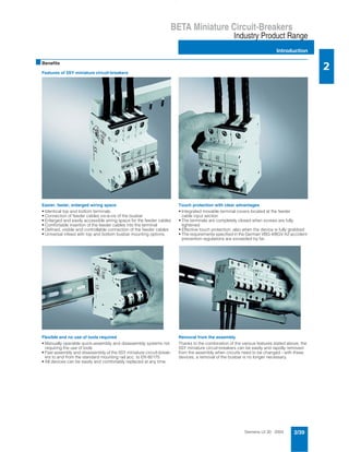
- 1. Siemens LV 30 · 2004 2/39 BETA Miniature Circuit-Breakers Industry Product Range Introduction 2 * This quantity or a multiple thereof can be ordered. ■Benefits Features of 5SY miniature circuit-breakers Easier, faster, enlarged wiring space • Identical top and bottom terminals • Connection of feeder cables vis-à-vis of the busbar • Enlarged and easily accessible wiring space for the feeder cables • Comfortable insertion of the feeder cables into the terminal • Defined, visible and controllable connection of the feeder cables • Universal infeed with top and bottom busbar mounting options. Touch protection with clear advantages • Integrated movable terminal covers located at the feeder cable input section • The terminals are completely closed when screws are fully tightened • Effective touch protection, also when the device is fully grabbed • The requirements specified in the German VBG 4/BGV A2 accident prevention regulations are exceeded by far. Flexible and no use of tools required • Manually operable quick-assembly and disassembly systems not requiring the use of tools • Fast assembly and disassembly of the 5SY miniature circuit-break- ers to and from the standard mounting rail acc. to EN 60175 • All devices can be easily and comfortably replaced at any time. Removal from the assembly Thanks to the combination of the various features stated above, the 5SY miniature circuit-breakers can be easily and rapidly removed from the assembly when circuits need to be changed - with these devices, a removal of the busbar is no longer necessary.
- 2. Siemens LV 30 · 20042/40 BETA Miniature Circuit-Breakers 6 kA 70 mm mounting depth Industry Product Range 2 * This quantity or a multiple thereof can be ordered. ■Area of application • Un: AC 230 V, 50-60 Hz • Standards: EN 60898, DIN VDE 0641 Part 11, IEC 60898 Characteristic B Line protection, mainly used for outlet circuits; no proof required regarding personal safety. Characteristic C General line protection, especially advantageous with higher in- rush currents (lamps, motors, etc.). ■Selection and ordering data ■Benefits Auxiliary switch (AS) • Can be retrofitted individually • Mounting with factory-installed clips • max. contact loading acc. to DIN VDE 0660 Part 200, EN 60947-5-1: 6 A, AC 230 V, AC-15 1 A, DC 220 V, DC-13 • Short-circuit protection ensured by circuit-breakers with characteristic B or C with In = 6 A or fuse gL 6 A • Conductor cross-section 0.5 to 2.5 mm2 ■Functions • Remote indication of the miniature circuit-breaker’s switching state: AS: ON/OFF • Connectable to instabus EIB and AS-Interface bus via binary inputs. ■Selection and ordering data In MW DC Characteristic B Pack. unit* Weight per unit approx. DC Characteristic C Pack. unit* Weight per unit approx. Order No. Order No. A kg kg 1-pole + N 2 1 - A 5SY6 002-7KV 12 0.132 4 - A 5SY6 004-7KV 12 0.132 6 A 5SY6 006-6KV 12 0.132 A 5SY6 006-7KV 12 0.132 8 - A 5SY6 008-7KV 12 0.132 10 A 5SY6 010-6KV 12 0.132 A 5SY6 010-7KV 12 0.132 13 A 5SY6 013-6KV 12 0.132 A 5SY6 013-7KV 12 0.132 16 A 5SY6 016-6KV 12 0.132 A 5SY6 016-7KV 12 0.132 20 A 5SY6 020-6KV 12 0.132 A 5SY6 020-7KV 12 0.132 25 A 5SY6 025-6KV 12 0.132 A 5SY6 025-7KV 12 0.132 32 A 5SY6 032-6KV 12 0.132 A 5SY6 032-7KV 12 0.132 40 A 5SY6 040-6KV 12 0.132 A 5SY6 040-7KV 12 0.132 2 1 N N I2_08258 instabus EIB input MCBAS MW DC Order No. Pack. unit* Weight per unit approx. kg Auxiliary switch (AS) 1 NO + 1 NC 0.5 A 5ST3 018-0KV 1 0.037 13 12 21 22
- 3. Siemens LV 30 · 2004 2/41 BETA Miniature Circuit-Breakers Industry Product Range 6 kA 70 mm mounting depth 2 * This quantity or a multiple thereof can be ordered. ■Area of application • Un: 230/400 V, 50-60 Hz, applicable in networks up to AC 250/440 V, DC 60 V per pole • Standards EN 60898, DIN VDE 0641 Part 11, IEC 60898 • Supplementary components can be retrofitted. Characteristic B Line protection, mainly used for outlet circuits; no proof required regarding personal safety. ■Selection and ordering data 1) Also suitable for 21 kW active power at DC 400 V (e.g. continuous-flow water heater with short-time operation) and 7 kW active power at AC 230 V (e.g. hot water storage tank in non-continuous operation). For continuous load applications, the use of miniature circuit-breakers of characteristic B or C and In = 40 A is recommended. All 5SY6 designs have been approved acc. to UL 1077 and CSA 22.2 No. 235-M 89 and can therefore be used as "supplementary protectors" up to AC 277 V (1-pole and 1-pole + N design) and AC 480 V (2-pole, 3-pole, 3-pole + N and 4-pole design). For supplementary components, please see page 2/57. For accessories, please see pages 2/60 and 2/61. In MW DC Characteristic B Pack. unit* Weight per unit approx.Order No. A kg 1-pole 6 1 A 5SY6 106-6 12 0.165 10 A 5SY6 110-6 12 0.165 13 A 5SY6 113-6 12 0.165 16 A 5SY6 116-6 12 0.165 20 B 5SY6 120-6 12 0.165 25 A 5SY6 125-6 12 0.165 321) A 5SY6 132-6 12 0.165 40 A 5SY6 140-6 12 0.165 50 A 5SY6 150-6 12 0.165 63 A 5SY6 163-6 12 0.165 1-pole + N 6 2 A 5SY6 506-6 6 0.330 10 A 5SY6 510-6 6 0.330 13 B 5SY6 513-6 6 0.330 16 A 5SY6 516-6 6 0.330 20 A 5SY6 520-6 6 0.330 25 A 5SY6 525-6 6 0.330 32 B 5SY6 532-6 6 0.330 40 B 5SY6 540-6 6 0.330 50 B 5SY6 550-6 6 0.330 63 B 5SY6 563-6 6 0.330 2-pole 6 2 A 5SY6 206-6 6 0.330 10 A 5SY6 210-6 6 0.330 13 A 5SY6 213-6 6 0.330 16 A 5SY6 216-6 6 0.330 20 A 5SY6 220-6 6 0.330 25 A 5SY6 225-6 6 0.330 32 B 5SY6 232-6 6 0.330 40 A 5SY6 240-6 6 0.330 50 B 5SY6 250-6 6 0.330 63 B 5SY6 263-6 6 0.330 3-pole 6 3 B 5SY6 306-6 4 0.495 10 B 5SY6 310-6 4 0.495 13 B 5SY6 313-6 4 0.495 16 A 5SY6 316-6 4 0.495 20 A 5SY6 320-6 4 0.495 25 A 5SY6 325-6 4 0.495 321) A 5SY6 332-6 4 0.495 40 B 5SY6 340-6 4 0.495 50 A 5SY6 350-6 4 0.495 63 A 5SY6 363-6 4 0.495 3-pole + N 6 4 B 5SY6 606-6 3 0.660 10 A 5SY6 610-6 3 0.660 13 B 5SY6 613-6 3 0.660 16 A 5SY6 616-6 3 0.660 20 B 5SY6 620-6 3 0.660 25 B 5SY6 625-6 3 0.660 32 A 5SY6 632-6 3 0.660 40 B 5SY6 640-6 3 0.660 50 B 5SY6 650-6 3 0.660 63 B 5SY6 663-6 3 0.660 4-pole 6 4 B 5SY6 406-6 3 0.660 10 A 5SY6 410-6 3 0.660 13 B 5SY6 413-6 3 0.660 16 A 5SY6 416-6 3 0.660 20 B 5SY6 420-6 3 0.660 25 B 5SY6 425-6 3 0.660 32 B 5SY6 432-6 3 0.660 40 B 5SY6 440-6 3 0.660 50 A 5SY6 450-6 3 0.660 63 A 5SY6 463-6 3 0.660 1 2 N N 1 2 1 2 3 4 2 1 4 3 6 5 1 2 3 4 5 6 N N 1 2 3 4 5 6 7 8 6 000 3V
- 4. Siemens LV 30 · 20042/42 BETA Miniature Circuit-Breakers 6 kA 70 mm mounting depth Industry Product Range 2 * This quantity or a multiple thereof can be ordered. 6 000 3V ■Area of application • Un: 230/400 V, 50-60 Hz, applicable in networks up to AC 250/440 V, DC 60 V per pole • Standards EN 60898, DIN VDE 0641 Part 11, IEC 60898 • Supplementary components can be retrofitted. Characteristic C General line protection, especially advantageous with higher in- rush currents (lamps, motors, etc.). Characteristic D Tripping range adapted to operating equipment involving signif- icant pulse generation (transformers, solenoid valves). ■Selection and ordering data 1) Also suitable for 21 kW active power at DC 400 V (e.g. continuous-flow water heater with short-time operation) and 7 kW active power at AC 230 V (e.g. hot water storage tank in non-continuous operation). For continuous load applications, the use of miniature circuit-breakers of characteristic B or C and In = 40 A is recommended. All 5SY6 designs have been approved acc. to UL 1077 and CSA 22.2 No. 235-M 89 and can therefore be used as "supplementary protectors" up to AC 277 V (1-pole and 1-pole + N design) and AC 480 V (2-pole, 3-pole, 3-pole + N and 4-pole design). For supplementary components, please see page 2/57. For accessories, please see pages 2/60 and 2/61. In MW DC Characteristic C Pack. unit* Weight per unit approx. DC Characteristic D Pack. unit* Weight per unit approx.Order No. Order No. A kg kg 1-pole 0.3 1 C 5SY6 114-7 12 0.165 C 5SY6 114-8 12 0.165 0.5 A 5SY6 105-7 12 0.165 C 5SY6 105-8 12 0.165 1 A 5SY6 101-7 12 0.165 A 5SY6 101-8 12 0.165 1.6 B 5SY6 115-7 12 0.165 C 5SY6 115-8 12 0.147 2 A 5SY6 102-7 12 0.165 A 5SY6 102-8 12 0.165 3 A 5SY6 103-7 12 0.165 A 5SY6 103-8 12 0.165 4 A 5SY6 104-7 12 0.165 A 5SY6 104-8 12 0.165 6 A 5SY6 106-7 12 0.165 A 5SY6 106-8 12 0.165 8 A 5SY6 108-7 12 0.165 A 5SY6 108-8 12 0.165 10 A 5SY6 110-7 12 0.165 A 5SY6 110-8 12 0.165 13 A 5SY6 113-7 12 0.165 C 5SY6 113-8 12 0.165 16 A 5SY6 116-7 12 0.165 A 5SY6 116-8 12 0.165 20 A 5SY6 120-7 12 0.165 A 5SY6 120-8 12 0.165 25 A 5SY6 125-7 12 0.165 A 5SY6 125-8 12 0.165 321) A 5SY6 132-7 12 0.165 C 5SY6 132-8 12 0.165 40 A 5SY6 140-7 12 0.165 C 5SY6 140-8 12 0.165 50 A 5SY6 150-7 12 0.165 C 5SY6 150-8 12 0.165 63 A 5SY6 163-7 12 0.165 C 5SY6 163-8 12 0.165 1-pole + N 0.3 2 A 5SY6 514-7 6 0.330 C 5SY6 514-8 6 0.330 0.5 A 5SY6 505-7 6 0.330 C 5SY6 505-8 6 0.330 1 C 5SY6 501-7 6 0.330 C 5SY6 501-8 6 0.330 1.6 C 5SY6 515-7 6 0.330 C 5SY6 515-8 6 0.330 2 A 5SY6 502-7 6 0.330 C 5SY6 502-8 6 0.330 3 C 5SY6 503-7 6 0.330 C 5SY6 503-8 6 0.330 4 A 5SY6 504-7 6 0.330 C 5SY6 504-8 6 0.330 6 A 5SY6 506-7 6 0.330 C 5SY6 506-8 6 0.330 8 C 5SY6 508-7 6 0.330 C 5SY6 508-8 6 0.330 10 A 5SY6 510-7 6 0.330 C 5SY6 510-8 6 0.330 13 A 5SY6 513-7 6 0.330 C 5SY6 513-8 6 0.330 16 A 5SY6 516-7 6 0.330 C 5SY6 516-8 6 0.330 20 A 5SY6 520-7 6 0.330 C 5SY6 520-8 6 0.330 25 A 5SY6 525-7 6 0.330 C 5SY6 525-8 6 0.330 32 A 5SY6 532-7 6 0.330 C 5SY6 532-8 6 0.330 40 A 5SY6 540-7 6 0.330 C 5SY6 540-8 6 0.330 50 A 5SY6 550-7 6 0.330 C 5SY6 550-8 6 0.330 63 C 5SY6 563-7 6 0.330 C 5SY6 563-8 6 0.330 2-pole 0.3 2 C 5SY6 214-7 6 0.330 C 5SY6 214-8 6 0.330 0.5 A 5SY6 205-7 6 0.330 A 5SY6 205-8 6 0.330 1 A 5SY6 201-7 6 0.330 A 5SY6 201-8 6 0.330 1.6 B 5SY6 215-7 6 0.330 A 5SY6 215-8 6 0.330 2 A 5SY6 202-7 6 0.330 A 5SY6 202-8 6 0.330 3 A 5SY6 203-7 6 0.330 A 5SY6 203-8 6 0.330 4 A 5SY6 204-7 6 0.330 A 5SY6 204-8 6 0.330 6 A 5SY6 206-7 6 0.330 A 5SY6 206-8 6 0.330 8 A 5SY6 208-7 6 0.330 A 5SY6 208-8 6 0.330 10 A 5SY6 210-7 6 0.330 A 5SY6 210-8 6 0.330 13 A 5SY6 213-7 6 0.330 C 5SY6 213-8 6 0.330 16 A 5SY6 216-7 6 0.330 A 5SY6 216-8 6 0.330 20 A 5SY6 220-7 6 0.330 A 5SY6 220-8 6 0.330 25 A 5SY6 225-7 6 0.330 A 5SY6 225-8 6 0.330 32 A 5SY6 232-7 6 0.330 A 5SY6 232-8 6 0.330 40 A 5SY6 240-7 6 0.330 C 5SY6 240-8 6 0.330 50 A 5SY6 250-7 6 0.330 C 5SY6 250-8 6 0.330 63 B 5SY6 263-7 6 0.330 C 5SY6 263-8 6 0.330 1 2 N N 1 2 1 2 3 4
- 5. Siemens LV 30 · 2004 2/43 BETA Miniature Circuit-Breakers Industry Product Range 6 kA 70 mm mounting depth 2 * This quantity or a multiple thereof can be ordered. ■Selection and ordering data 1) Also suitable for 21 kW active power at DC 400 V (e.g. continuous-flow water heater with short-time operation) and 7 kW active power at AC 230 V (e.g. hot water storage tank in non-continuous operation). For continuous load applications, the use of miniature circuit-breakers of characteristic B or C and In = 40 A is recommended. All 5SY6 designs have been approved acc. to UL 1077 and CSA 22.2 No. 235-M 89 and can therefore be used as "supplementary protectors" up to AC 277 V (1-pole and 1-pole + N design) and AC 480 V (2-pole, 3-pole, 3-pole + N and 4-pole design). For supplementary components, please see page 2/57. For accessories, please see pages 2/60 and 2/61. In MW DC Characteristic C Pack. unit* Weight per unit approx. DC Characteristic D Pack. unit* Weight per unit approx. Order No. Order No. A kg kg 3-pole 0.3 3 C 5SY6 314-7 4 0.495 C 5SY6 314-8 4 0.495 0.5 C 5SY6 305-7 4 0.495 C 5SY6 305-8 4 0.495 1 C 5SY6 301-7 4 0.495 A 5SY6 301-8 4 0.495 1.6 C 5SY6 315-7 4 0.495 C 5SY6 315-8 4 0.495 2 A 5SY6 302-7 4 0.495 A 5SY6 302-8 4 0.495 3 A 5SY6 303-7 4 0.495 A 5SY6 303-8 4 0.495 4 A 5SY6 304-7 4 0.495 A 5SY6 304-8 4 0.495 6 A 5SY6 306-7 4 0.495 A 5SY6 306-8 4 0.495 8 C 5SY6 308-7 4 0.495 C 5SY6 308-8 4 0.495 10 A 5SY6 310-7 4 0.495 A 5SY6 310-8 4 0.495 13 A 5SY6 313-7 4 0.495 C 5SY6 313-8 4 0.495 16 A 5SY6 316-7 4 0.495 A 5SY6 316-8 4 0.495 20 A 5SY6 320-7 4 0.495 A 5SY6 320-8 4 0.495 25 A 5SY6 325-7 4 0.495 A 5SY6 325-8 4 0.495 321) A 5SY6 332-7 4 0.495 A 5SY6 332-8 4 0.495 40 A 5SY6 340-7 4 0.495 A 5SY6 340-8 4 0.495 50 A 5SY6 350-7 4 0.495 A 5SY6 350-8 4 0.495 63 A 5SY6 363-7 4 0.495 A 5SY6 363-8 4 0.495 3-pole + N 0.3 4 C 5SY6 614-7 3 0.660 C 5SY6 614-8 3 0.660 0.5 C 5SY6 605-7 3 0.660 C 5SY6 605-8 3 0.660 1 C 5SY6 601-7 3 0.660 C 5SY6 601-8 3 0.660 1.6 C 5SY6 615-7 3 0.660 C 5SY6 615-8 3 0.660 2 C 5SY6 602-7 3 0.660 C 5SY6 602-8 3 0.660 3 C 5SY6 603-7 3 0.660 C 5SY6 603-8 3 0.660 4 C 5SY6 604-7 3 0.660 C 5SY6 604-8 3 0.660 6 C 5SY6 606-7 3 0.660 C 5SY6 606-8 3 0.660 8 C 5SY6 608-7 3 0.660 C 5SY6 608-8 3 0.660 10 A 5SY6 610-7 3 0.660 C 5SY6 610-8 3 0.660 13 A 5SY6 613-7 3 0.660 C 5SY6 613-8 3 0.660 16 A 5SY6 616-7 3 0.660 C 5SY6 616-8 3 0.660 20 A 5SY6 620-7 3 0.660 C 5SY6 620-8 3 0.660 25 A 5SY6 625-7 3 0.660 C 5SY6 625-8 3 0.660 32 A 5SY6 632-7 3 0.660 C 5SY6 632-8 3 0.660 40 A 5SY6 640-7 3 0.660 C 5SY6 640-8 3 0.660 50 A 5SY6 650-7 3 0.660 C 5SY6 650-8 3 0.660 63 A 5SY6 663-7 3 0.660 C 5SY6 663-8 3 0.660 4-pole 0.3 4 C 5SY6 414-7 3 0.660 C 5SY6 414-8 3 0.660 0.5 C 5SY6 405-7 3 0.660 C 5SY6 405-8 3 0.660 1 A 5SY6 401-7 3 0.660 C 5SY6 401-8 3 0.660 1.6 C 5SY6 415-7 3 0.660 C 5SY6 415-8 3 0.660 2 C 5SY6 402-7 3 0.660 C 5SY6 402-8 3 0.660 3 C 5SY6 403-7 3 0.660 C 5SY6 403-8 3 0.660 4 A 5SY6 404-7 3 0.660 C 5SY6 404-8 3 0.660 6 A 5SY6 406-7 3 0.660 C 5SY6 406-8 3 0.660 8 C 5SY6 408-7 3 0.660 C 5SY6 408-8 3 0.660 10 A 5SY6 410-7 3 0.660 A 5SY6 410-8 3 0.660 13 A 5SY6 413-7 3 0.660 C 5SY6 413-8 3 0.660 16 A 5SY6 416-7 3 0.660 A 5SY6 416-8 3 0.660 20 A 5SY6 420-7 3 0.660 A 5SY6 420-8 3 0.660 25 A 5SY6 425-7 3 0.660 A 5SY6 425-8 3 0.660 32 A 5SY6 432-7 3 0.660 A 5SY6 432-8 3 0.660 40 A 5SY6 440-7 3 0.660 A 5SY6 440-8 3 0.660 50 A 5SY6 450-7 3 0.660 A 5SY6 450-8 3 0.660 63 A 5SY6 463-7 3 0.660 A 5SY6 463-8 3 0.660 2 1 4 3 6 5 1 2 3 4 5 6 N N 1 2 3 4 5 6 7 8 6,000 3V
- 6. Siemens LV 30 · 20042/44 BETA Miniature Circuit-Breakers 10 kA 70 mm mounting depth Industry Product Range 2 * This quantity or a multiple thereof can be ordered. ■Area of application • Un: 230/400 V, 50-60 Hz, applicable in networks up to AC 250/440 V, DC 60 V per pole • Standards EN 60898, DIN VDE 0641 Part 11, IEC 60898 • Supplementary components can be retrofitted. Characteristic A • For limited semiconductor protection • Protection of measuring circuits with converters • Protection of circuits with large cable lengths and a require- ment for off-switching after 0.4 s acc. to DIN VDE 0100 Part 410. Characteristic B Line protection, mainly used for outlet circuits; no proof required regarding personal safety. ■Selection and ordering data 1) Only applicable for 5SY4 132-6: Also suitable for 21 kW active power at DC 400 V (e.g. continuous-flow water heater with short-time operation) and 7 kW active power at AC 230 V (e.g. hot water storage tank in non-continu- ous operation). For continuous load applications, the use of miniature circuit-breakers of characteristic B or C and In = 40 A is recommended. All 5SY4 designs have been approved acc. to UL 1077 and CSA 22.2 No. 235-M 89 and can therefore be used as "supplementary protectors" up to AC 277 V (1-pole and 1-pole + N design) and AC 480 V (2-pole, 3-pole, 3-pole + N and 4-pole design). For supplementary components, please see pages 2/55, 2/57 and 2/59. For accessories, please see pages 2/60 and 2/61. In MW DC Characteristic A Pack. unit* Weight per unit approx. DC Characteristic B Pack. unit* Weight per unit approx.Order No. Order No. A kg kg 1-pole 1 1 C 5SY4 101-5 12 0.165 - 1.6 A 5SY4 115-5 12 0.165 - 2 B 5SY4 102-5 12 0.165 - 3 C 5SY4 103-5 12 0.165 - 4 A 5SY4 104-5 12 0.165 - 6 A 5SY4 106-5 12 0.165 A 5SY4 106-6 12 0.165 8 C 5SY4 108-5 12 0.165 - 10 B 5SY4 110-5 12 0.165 A 5SY4 110-6 12 0.165 13 C 5SY4 113-5 12 0.165 A 5SY4 113-6 12 0.165 16 A 5SY4 116-5 12 0.165 A 5SY4 116-6 12 0.165 20 A 5SY4 120-5 12 0.165 A 5SY4 120-6 12 0.165 25 C 5SY4 125-5 12 0.165 A 5SY4 125-6 12 0.165 32 1) C 5SY4 132-5 12 0.165 A 5SY4 132-6 12 0.165 40 C 5SY4 140-5 12 0.165 B 5SY4 140-6 12 0.165 50 C 5SY4 150-5 12 0.165 A 5SY4 150-6 12 0.165 63 C 5SY4 163-5 12 0.165 A 5SY4 163-6 12 0.165 1-pole + N 1 2 C 5SY4 501-5 6 0.330 - 1.6 C 5SY4 515-5 6 0.330 - 2 C 5SY4 502-5 6 0.330 - 3 C 5SY4 503-5 6 0.330 - 4 C 5SY4 504-5 6 0.330 - 6 C 5SY4 506-5 6 0.330 B 5SY4 506-6 6 0.330 8 C 5SY4 508-5 6 0.330 - 10 C 5SY4 510-5 6 0.330 A 5SY4 510-6 6 0.330 13 C 5SY4 513-5 6 0.330 A 5SY4 513-6 6 0.330 16 C 5SY4 516-5 6 0.330 A 5SY4 516-6 6 0.330 20 C 5SY4 520-5 6 0.330 C 5SY4 520-6 6 0.330 25 C 5SY4 525-5 6 0.330 C 5SY4 525-6 6 0.330 32 C 5SY4 532-5 6 0.330 C 5SY4 532-6 6 0.330 40 C 5SY4 540-5 6 0.330 C 5SY4 540-6 6 0.330 50 C 5SY4 550-5 6 0.330 C 5SY4 550-6 6 0.330 63 C 5SY4 563-5 6 0.330 C 5SY4 563-6 6 0.330 2-pole 1 2 A 5SY4 201-5 6 0.330 - 1.6 C 5SY4 215-5 6 0.330 - 2 C 5SY4 202-5 6 0.330 - 3 C 5SY4 203-5 6 0.330 - 4 C 5SY4 204-5 6 0.330 - 6 C 5SY4 206-5 6 0.330 A 5SY4 206-6 6 0.330 8 C 5SY4 208-5 6 0.330 - 10 C 5SY4 210-5 6 0.330 A 5SY4 210-6 6 0.330 13 C 5SY4 213-5 6 0.330 B 5SY4 213-6 6 0.330 16 C 5SY4 216-5 6 0.330 A 5SY4 216-6 6 0.330 20 A 5SY4 220-5 6 0.330 A 5SY4 220-6 6 0.330 25 C 5SY4 225-5 6 0.330 A 5SY4 225-6 6 0.330 32 C 5SY4 232-5 6 0.330 B 5SY4 232-6 6 0.330 40 A 5SY4 240-5 6 0.330 A 5SY4 240-6 6 0.330 50 C 5SY4 250-5 6 0.330 C 5SY4 250-6 6 0.330 63 C 5SY4 263-5 6 0.330 C 5SY4 263-6 6 0.330 1 2 N N 1 2 1 2 3 4 10 000 3V
- 7. Siemens LV 30 · 2004 2/45 BETA Miniature Circuit-Breakers Industry Product Range 10 kA 70 mm mounting depth 2 * This quantity or a multiple thereof can be ordered. ■Selection and ordering data 1) Only applicable for 5SY4 332-6: Also suitable for 21 kW active power at DC 400 V (e.g. continuous-flow water heater with short-time operation) and 7 kW active power at AC 230 V (e.g. hot water storage tank in non-continuous operation). For continuous load applications, the use of miniature circuit-breakers of characteristic B or C and In = 40 A is recommended. All 5SY4 designs have been approved acc. to UL 1077 and CSA 22.2 No. 235-M 89 and can therefore be used as "supplementary protectors" up to AC 277 V (1-pole and 1-pole + N design) and AC 480 V (2-pole, 3-pole, 3-pole + N and 4-pole design). For supplementary components, please see pages 2/55, 2/57 and 2/59. For accessories, please see pages 2/60 and 2/61. In MW DC Characteristic A Pack. unit* Weight per unit approx. DC Characteristic B Pack. unit* Weight per unit approx. Order No. Order No. A kg kg 3-pole 1 3 C 5SY4 301-5 4 0.495 - 1.6 C 5SY4 315-5 4 0.495 - 2 C 5SY4 302-5 4 0.495 - 3 C 5SY4 303-5 4 0.495 - 4 C 5SY4 304-5 4 0.495 - 6 C 5SY4 306-5 4 0.495 A 5SY4 306-6 4 0.495 8 C 5SY4 308-5 4 0.495 - 10 A 5SY4 310-5 4 0.495 A 5SY4 310-6 4 0.495 13 C 5SY4 313-5 4 0.495 C 5SY4 313-6 4 0.495 16 C 5SY4 316-5 4 0.495 A 5SY4 316-6 4 0.495 20 C 5SY4 320-5 4 0.495 A 5SY4 320-6 4 0.495 25 A 5SY4 325-5 4 0.495 A 5SY4 325-6 4 0.495 32 1) A 5SY4 332-5 4 0.495 A 5SY4 332-6 4 0.495 40 C 5SY4 340-5 4 0.495 B 5SY4 340-6 4 0.495 50 C 5SY4 350-5 4 0.495 A 5SY4 350-6 4 0.495 63 C 5SY4 363-5 4 0.495 A 5SY4 363-6 4 0.495 3-pole + N 1 4 C 5SY4 601-5 3 0.660 - 1.6 C 5SY4 615-5 3 0.660 - 2 C 5SY4 602-5 3 0.660 - 3 C 5SY4 603-5 3 0.660 - 4 C 5SY4 604-5 3 0.660 - 6 C 5SY4 606-5 3 0.660 C 5SY4 606-6 3 0.660 8 C 5SY4 608-5 3 0.660 - 10 C 5SY4 610-5 3 0.660 A 5SY4 610-6 3 0.660 13 C 5SY4 613-5 3 0.660 C 5SY4 613-6 3 0.660 16 C 5SY4 616-5 3 0.660 C 5SY4 616-6 3 0.660 20 C 5SY4 620-5 3 0.660 A 5SY4 620-6 3 0.660 25 C 5SY4 625-5 3 0.660 A 5SY4 625-6 3 0.660 32 C 5SY4 632-5 3 0.660 A 5SY4 632-6 3 0.660 40 C 5SY4 640-5 3 0.660 C 5SY4 640-6 3 0.660 50 C 5SY4 650-5 3 0.660 C 5SY4 650-6 3 0.660 63 C 5SY4 663-5 3 0.660 C 5SY4 663-6 3 0.660 4-pole 1 4 C 5SY4 401-5 3 0.660 - 1.6 C 5SY4 415-5 3 0.660 - 2 C 5SY4 402-5 3 0.660 - 3 C 5SY4 403-5 3 0.660 - 4 C 5SY4 404-5 3 0.660 - 6 C 5SY4 406-5 3 0.660 C 5SY4 406-6 3 0.660 8 C 5SY4 408-5 3 0.660 - 10 C 5SY4 410-5 3 0.660 A 5SY4 410-6 3 0.660 13 C 5SY4 413-5 3 0.660 C 5SY4 413-6 3 0.660 16 C 5SY4 416-5 3 0.660 A 5SY4 416-6 3 0.660 20 C 5SY4 420-5 3 0.660 C 5SY4 420-6 3 0.660 25 C 5SY4 425-5 3 0.660 A 5SY4 425-6 3 0.660 32 C 5SY4 432-5 3 0.660 A 5SY4 432-6 3 0.660 40 C 5SY4 440-5 3 0.660 A 5SY4 440-6 3 0.660 50 C 5SY4 450-5 3 0.660 C 5SY4 450-6 3 0.660 63 C 5SY4 463-5 3 0.660 A 5SY4 463-6 3 0.660 2 1 4 3 6 5 1 2 3 4 5 6 N N 1 2 3 4 5 6 7 8 10 000 3V
- 8. Siemens LV 30 · 20042/46 BETA Miniature Circuit-Breakers 10 kA 70 mm mounting depth Industry Product Range 2 * This quantity or a multiple thereof can be ordered. 10 000 3V ■Area of application Characteristic C General line protection, especially advantageous with higher in- rush currents (lamps, motors, etc.). Characteristic D Tripping range adapted to operating equipment involving signif- icant pulse generation (transformers, solenoid valves). ■Selection and ordering data 1) Only applicable for 5SY4 132-7: Also suitable for 21 kW active power at DC 400 V (e.g. continuous-flow water heater with short-time operation) and 7 kW active power at AC 230 V (e.g. hot water storage tank in non-continuous operation). For continuous load applications, the use of miniature circuit-breakers of characteristic B or C and In = 40 A is recommended. All 5SY4 designs have been approved acc. to UL 1077 and CSA 22.2 No. 235-M 89 and can therefore be used as "supplementary protectors" up to AC 277 V (1-pole and 1-pole + N design) and AC 480 V (2-pole, 3-pole, 3-pole + N and 4-pole design). For supplementary components, please see pages 2/55, 2/57 and 2/59. For accessories, please see pages 2/60 and 2/61. In MW DC Characteristic C Pack. unit* Weight per unit approx. DC Characteristic D Pack. unit* Weight per unit approx. Order No. Order No. A kg kg 1-pole 0.3 1 C 5SY4 114-7 12 0.165 C 5SY4 114-8 12 0.165 0.5 A 5SY4 105-7 12 0.165 C 5SY4 105-8 12 0.165 1 A 5SY4 101-7 12 0.165 C 5SY4 101-8 12 0.165 1.6 B 5SY4 115-7 12 0.165 C 5SY4 115-8 12 0.165 2 A 5SY4 102-7 12 0.165 A 5SY4 102-8 12 0.165 3 A 5SY4 103-7 12 0.165 A 5SY4 103-8 12 0.165 4 A 5SY4 104-7 12 0.165 C 5SY4 104-8 12 0.165 6 A 5SY4 106-7 12 0.165 A 5SY4 106-8 12 0.165 8 A 5SY4 108-7 12 0.165 C 5SY4 108-8 12 0.165 10 A 5SY4 110-7 12 0.165 A 5SY4 110-8 12 0.165 13 A 5SY4 113-7 12 0.165 C 5SY4 113-8 12 0.165 16 A 5SY4 116-7 12 0.165 A 5SY4 116-8 12 0.165 20 A 5SY4 120-7 12 0.165 A 5SY4 120-8 12 0.165 25 A 5SY4 125-7 12 0.165 C 5SY4 125-8 12 0.165 32 1) A 5SY4 132-7 12 0.165 C 5SY4 132-8 12 0.165 40 A 5SY4 140-7 12 0.165 C 5SY4 140-8 12 0.165 50 A 5SY4 150-7 12 0.165 A 5SY4 150-8 12 0.165 63 A 5SY4 163-7 12 0.165 C 5SY4 163-8 12 0.165 1-pole + N 0.3 2 C 5SY4 514-7 6 0.330 C 5SY4 514-8 6 0.330 0.5 A 5SY4 505-7 6 0.330 C 5SY4 505-8 6 0.330 1 C 5SY4 501-7 6 0.330 C 5SY4 501-8 6 0.330 1.6 C 5SY4 515-7 6 0.330 C 5SY4 515-8 6 0.330 2 A 5SY4 502-7 6 0.330 C 5SY4 502-8 6 0.330 3 C 5SY4 503-7 6 0.330 C 5SY4 503-8 6 0.330 4 A 5SY4 504-7 6 0.330 C 5SY4 504-8 6 0.330 6 A 5SY4 506-7 6 0.330 C 5SY4 506-8 6 0.330 8 C 5SY4 508-7 6 0.330 C 5SY4 508-8 6 0.330 10 A 5SY4 510-7 6 0.330 A 5SY4 510-8 6 0.330 13 C 5SY4 513-7 6 0.330 C 5SY4 513-8 6 0.330 16 A 5SY4 516-7 6 0.330 B 5SY4 516-8 6 0.330 20 A 5SY4 520-7 6 0.330 A 5SY4 520-8 6 0.330 25 A 5SY4 525-7 6 0.330 C 5SY4 525-8 6 0.330 32 A 5SY4 532-7 6 0.330 C 5SY4 532-8 6 0.330 40 A 5SY4 540-7 6 0.330 C 5SY4 540-8 6 0.330 50 C 5SY4 550-7 6 0.330 C 5SY4 550-8 6 0.330 63 C 5SY4 563-7 6 0.330 C 5SY4 563-8 6 0.330 2-pole 0.3 2 C 5SY4 214-7 6 0.330 C 5SY4 214-8 6 0.330 0.5 A 5SY4 205-7 6 0.330 B 5SY4 205-8 6 0.330 1 A 5SY4 201-7 6 0.330 A 5SY4 201-8 6 0.330 1.6 B 5SY4 215-7 6 0.330 C 5SY4 215-8 6 0.330 2 A 5SY4 202-7 6 0.330 A 5SY4 202-8 6 0.330 3 A 5SY4 203-7 6 0.330 A 5SY4 203-8 6 0.330 4 A 5SY4 204-7 6 0.330 A 5SY4 204-8 6 0.330 6 A 5SY4 206-7 6 0.330 A 5SY4 206-8 6 0.330 8 A 5SY4 208-7 6 0.330 C 5SY4 208-8 6 0.330 10 A 5SY4 210-7 6 0.330 A 5SY4 210-8 6 0.330 13 A 5SY4 213-7 6 0.330 C 5SY4 213-8 6 0.330 16 A 5SY4 216-7 6 0.330 A 5SY4 216-8 6 0.330 20 A 5SY4 220-7 6 0.330 A 5SY4 220-8 6 0.330 25 A 5SY4 225-7 6 0.330 A 5SY4 225-8 6 0.330 32 A 5SY4 232-7 6 0.330 A 5SY4 232-8 6 0.330 40 A 5SY4 240-7 6 0.330 B 5SY4 240-8 6 0.330 50 A 5SY4 250-7 6 0.330 B 5SY4 250-8 6 0.330 63 A 5SY4 263-7 6 0.330 C 5SY4 263-8 6 0.330 1 2 N N 1 2 1 2 3 4
- 9. Siemens LV 30 · 2004 2/47 BETA Miniature Circuit-Breakers Industry Product Range 10 kA 70 mm mounting depth 2 * This quantity or a multiple thereof can be ordered. 10 000 3V ■Selection and ordering data You can order this amount or a multiple of this amount. 1) Only applicable for 5SY4 332-7 and 5SY7 132-6: Also suitable for 21 kW active power at DC 400 V (e.g. continuous-flow water heater with short-time operation) and 7 kW active power at AC 230 V (e.g. hot water storage tank in non-continuous operation). For continuous load applications, the use of miniature circuit-breakers of characteristic B or C and In = 40 A is recommended. Please note for pages 2/47 and 2/48: All 5SY4 and 5SY7 designs have been approved acc. to UL 1077 and CSA 22.2 No. 235-M 89 and can therefore be used as "supplementary protec- tors" up to AC 277 V (1-pole and 1-pole + N design) and AC 480 V (2-pole, 3-pole, 3-pole + N and 4-pole design). The following cross-references and footnotes apply for pages 2/47 and 2/48: For supplementary components, please see pages 2/55, 2/57 and 2/59. For accessories, please see pages 2/60 and 2/61. In MW DC Characteristic C Pack. unit* Weight per unit approx. DC Characteristic D Pack. unit* Weight per unit approx. Order No. Order No. A kg kg 3-pole 0.3 3 C 5SY4 314-7 4 0.495 C 5SY4 314-8 4 0.495 0.5 A 5SY4 305-7 4 0.495 C 5SY4 305-8 4 0.495 1 C 5SY4 301-7 4 0.495 C 5SY4 301-8 4 0.495 1.6 C 5SY4 315-7 4 0.495 C 5SY4 315-8 4 0.495 2 A 5SY4 302-7 4 0.495 A 5SY4 302-8 4 0.495 3 A 5SY4 303-7 4 0.495 C 5SY4 303-8 4 0.495 4 A 5SY4 304-7 4 0.495 A 5SY4 304-8 4 0.495 6 A 5SY4 306-7 4 0.495 A 5SY4 306-8 4 0.495 8 C 5SY4 308-7 4 0.495 C 5SY4 308-8 4 0.495 10 A 5SY4 310-7 4 0.495 A 5SY4 310-8 4 0.495 13 A 5SY4 313-7 4 0.495 A 5SY4 313-8 4 0.495 16 A 5SY4 316-7 4 0.495 A 5SY4 316-8 4 0.495 20 A 5SY4 320-7 4 0.495 A 5SY4 320-8 4 0.495 25 A 5SY4 325-7 4 0.495 A 5SY4 325-8 4 0.495 32 1) A 5SY4 332-7 4 0.495 A 5SY4 332-8 4 0.495 40 A 5SY4 340-7 4 0.495 A 5SY4 340-8 4 0.495 50 A 5SY4 350-7 4 0.495 A 5SY4 350-8 4 0.495 63 A 5SY4 363-7 4 0.495 A 5SY4 363-8 4 0.495 3-pole + N 0.3 4 C 5SY4 614-7 3 0.660 C 5SY4 614-8 3 0.660 0.5 C 5SY4 605-7 3 0.660 C 5SY4 605-8 3 0.660 1 C 5SY4 601-7 3 0.660 C 5SY4 601-8 3 0.660 1.6 C 5SY4 615-7 3 0.660 C 5SY4 615-8 3 0.660 2 C 5SY4 602-7 3 0.660 C 5SY4 602-8 3 0.660 3 C 5SY4 603-7 3 0.660 C 5SY4 603-8 3 0.660 4 C 5SY4 604-7 3 0.660 C 5SY4 604-8 3 0.660 6 A 5SY4 606-7 3 0.660 C 5SY4 606-8 3 0.660 8 C 5SY4 608-7 3 0.660 C 5SY4 608-8 3 0.660 10 A 5SY4 610-7 3 0.660 C 5SY4 610-8 3 0.660 13 A 5SY4 613-7 3 0.660 C 5SY4 613-8 3 0.660 16 A 5SY4 616-7 3 0.660 B 5SY4 616-8 3 0.660 20 A 5SY4 620-7 3 0.660 A 5SY4 620-8 3 0.660 25 A 5SY4 625-7 3 0.660 A 5SY4 625-8 3 0.660 32 A 5SY4 632-7 3 0.660 A 5SY4 632-8 3 0.660 40 A 5SY4 640-7 3 0.660 A 5SY4 640-8 3 0.660 50 A 5SY4 650-7 3 0.660 A 5SY4 650-8 3 0.660 63 A 5SY4 663-7 3 0.660 B 5SY4 663-8 3 0.660 4-pole 0.3 4 C 5SY4 414-7 3 0.660 C 5SY4 414-8 3 0.660 0.5 C 5SY4 405-7 3 0.660 C 5SY4 405-8 3 0.660 1 C 5SY4 401-7 3 0.660 C 5SY4 401-8 3 0.660 1.6 C 5SY4 415-7 3 0.660 C 5SY4 415-8 3 0.660 2 A 5SY4 402-7 3 0.660 C 5SY4 402-8 3 0.660 3 C 5SY4 403-7 3 0.660 C 5SY4 403-8 3 0.660 4 C 5SY4 404-7 3 0.660 C 5SY4 404-8 3 0.660 6 A 5SY4 406-7 3 0.660 C 5SY4 406-8 3 0.660 8 C 5SY4 408-7 3 0.660 C 5SY4 408-8 3 0.660 10 A 5SY4 410-7 3 0.660 A 5SY4 410-8 3 0.660 13 C 5SY4 413-7 3 0.660 C 5SY4 413-8 3 0.660 16 A 5SY4 416-7 3 0.660 A 5SY4 416-8 3 0.660 20 A 5SY4 420-7 3 0.660 A 5SY4 420-8 3 0.660 25 A 5SY4 425-7 3 0.660 A 5SY4 425-8 3 0.660 32 A 5SY4 432-7 3 0.660 A 5SY4 432-8 3 0.660 40 A 5SY4 440-7 3 0.660 C 5SY4 440-8 3 0.660 50 A 5SY4 450-7 3 0.660 A 5SY4 450-8 3 0.660 63 A 5SY4 463-7 3 0.660 A 5SY4 463-8 3 0.660 2 1 4 3 6 5 1 2 3 4 5 6 N N 1 2 3 4 5 6 7 8
- 10. Siemens LV 30 · 20042/48 BETA Miniature Circuit-Breakers 15 kA 70 mm mounting depth Industry Product Range 2 * This quantity or a multiple thereof can be ordered. ■Area of application • Un: 230/400 V, 50-60 Hz, applicable in networks up to AC 250/440 V, DC 60 V per pole Standards EN 60898, DIN VDE 0641 Part 11, IEC 60898 Supplementary components can be retrofitted. Characteristic B Line protection, mainly used for outlet circuits; no proof required regarding personal safety. ■Selection and ordering data Please see the footnote on page 2/49. In MW DC Characteristic B Pack. unit* Weight per unit approx.Order No. A kg 1-pole 6 1 B 5SY7 106-6 12 0.165 10 A 5SY7 110-6 12 0.165 13 C 5SY7 113-6 12 0.165 16 A 5SY7 116-6 12 0.165 20 C 5SY7 120-6 12 0.165 25 C 5SY7 125-6 12 0.165 32 1) C 5SY7 132-6 12 0.165 40 C 5SY7 140-6 12 0.165 50 C 5SY7 150-6 12 0.165 63 C 5SY7 163-6 12 0.165 1-pole + N 6 2 C 5SY7 506-6 6 0.330 10 C 5SY7 510-6 6 0.330 13 C 5SY7 513-6 6 0.330 16 C 5SY7 516-6 6 0.330 20 C 5SY7 520-6 6 0.330 25 C 5SY7 525-6 6 0.330 32 C 5SY7 532-6 6 0.330 40 C 5SY7 540-6 6 0.330 50 C 5SY7 550-6 6 0.330 63 C 5SY7 563-6 6 0.330 2-pole 6 2 A 5SY7 206-6 6 0.330 10 B 5SY7 210-6 6 0.330 13 C 5SY7 213-6 6 0.330 16 C 5SY7 216-6 6 0.330 20 C 5SY7 220-6 6 0.330 25 A 5SY7 225-6 6 0.330 32 C 5SY7 232-6 6 0.330 40 C 5SY7 240-6 6 0.330 50 C 5SY7 250-6 6 0.330 63 C 5SY7 263-6 6 0.330 3-pole 6 3 C 5SY7 306-6 4 0.495 10 A 5SY7 310-6 4 0.495 13 C 5SY7 313-6 4 0.495 16 B 5SY7 316-6 4 0.495 20 C 5SY7 320-6 4 0.495 25 A 5SY7 325-6 4 0.495 32 C 5SY7 332-6 4 0.495 40 C 5SY7 340-6 4 0.495 50 C 5SY7 350-6 4 0.495 63 C 5SY7 363-6 4 0.495 3-pole + N 6 4 C 5SY7 606-6 3 0.660 10 C 5SY7 610-6 3 0.660 13 C 5SY7 613-6 3 0.660 16 B 5SY7 616-6 3 0.660 20 B 5SY7 620-6 3 0.660 25 C 5SY7 625-6 3 0.660 32 C 5SY7 632-6 3 0.660 40 C 5SY7 640-6 3 0.660 50 C 5SY7 650-6 3 0.660 63 C 5SY7 663-6 3 0.660 4-pole 6 4 C 5SY7 406-6 3 0.660 10 A 5SY7 410-6 3 0.660 13 C 5SY7 413-6 3 0.660 16 C 5SY7 416-6 3 0.660 20 A 5SY7 420-6 3 0.660 25 C 5SY7 425-6 3 0.660 32 C 5SY7 432-6 3 0.660 40 C 5SY7 440-6 3 0.660 50 C 5SY7 450-6 3 0.660 63 C 5SY7 463-6 3 0.660 1 2 N N 1 2 1 2 3 4 2 1 4 3 6 5 1 2 3 4 5 6 N N 1 2 3 4 5 6 7 8 15 000 3V
- 11. Siemens LV 30 · 2004 2/49 BETA Miniature Circuit-Breakers Industry Product Range 15 kA 70 mm mounting depth 2 * This quantity or a multiple thereof can be ordered. ■Area of application Characteristic C General line protection, especially advantageous with higher in- rush currents (lamps, motors, etc.,). Characteristic D Tripping range adapted to operating equipment involving signif- icant pulse generation (transformers, solenoid valves). ■Selection and ordering data The following footnotes apply to pages 2/48 and 2/49: 1) .Only applicable for 5SY7 132-6 and 5SY7 132-7: Also suitable for 21 kW active power at DC 400 V (e.g. continuous-flow water heater with short-time operation) and 7 kW active power at AC 230 V (e.g. hot water storage tank in non-continuous operation). For continuous load applications, the use of miniature circuit-breakers of characteristic B or C and In = 40 A is recommended. All 5SY7 designs have been approved acc. to UL 1077 and CSA 22.2 No. 235-M 89 and can therefore be used as "supplementary protectors" up to AC 277 V (1-pole and 1-pole + N design) and AC 480 V (2-pole, 3-pole, 3-pole + N and 4-pole design). For supplementary components, please see pages 2/55, 2/57 and 2/59. For accessories, please see pages 2/60 and 2/61. In MW DC Characteristic C Pack. unit* Weight per unit approx. DC Characteristic D Pack. unit* Weight per unit approx. Order No. Order No. A kg kg 1-pole 0.3 1 C 5SY7 114-7 12 0.165 C 5SY7 114-8 12 0.165 0.5 C 5SY7 105-7 12 0.165 C 5SY7 105-8 12 0.165 1 A 5SY7 101-7 12 0.165 C 5SY7 101-8 12 0.165 1.6 A 5SY7 115-7 12 0.165 C 5SY7 115-8 12 0.165 2 A 5SY7 102-7 12 0.165 C 5SY7 102-8 12 0.165 3 C 5SY7 103-7 12 0.165 C 5SY7 103-8 12 0.165 4 A 5SY7 104-7 12 0.165 C 5SY7 104-8 12 0.165 6 A 5SY7 106-7 12 0.165 C 5SY7 106-8 12 0.165 8 A 5SY7 108-7 12 0.165 C 5SY7 108-8 12 0.165 10 A 5SY7 110-7 12 0.165 A 5SY7 110-8 12 0.165 13 C 5SY7 113-7 12 0.165 C 5SY7 113-8 12 0.165 16 A 5SY7 116-7 12 0.165 C 5SY7 116-8 12 0.165 20 A 5SY7 120-7 12 0.165 C 5SY7 120-8 12 0.165 25 A 5SY7 125-7 12 0.165 C 5SY7 125-8 12 0.165 32 1) C 5SY7 132-7 12 0.165 C 5SY7 132-8 12 0.165 40 C 5SY7 140-7 12 0.165 C 5SY7 140-8 12 0.165 50 C 5SY7 150-7 12 0.165 C 5SY7 150-8 12 0.165 63 C 5SY7 163-7 12 0.165 C 5SY7 163-8 12 0.165 1-pole + N 0.3 2 C 5SY7 514-7 6 0.330 C 5SY7 514-8 6 0.330 0.5 C 5SY7 505-7 6 0.330 C 5SY7 505-8 6 0.330 1 C 5SY7 501-7 6 0.330 C 5SY7 501-8 6 0.330 1.6 C 5SY7 515-7 6 0.330 C 5SY7 515-8 6 0.330 2 A 5SY7 502-7 6 0.330 C 5SY7 502-8 6 0.330 3 C 5SY7 503-7 6 0.330 C 5SY7 503-8 6 0.330 4 A 5SY7 504-7 6 0.330 C 5SY7 504-8 6 0.330 6 A 5SY7 506-7 6 0.330 C 5SY7 506-8 6 0.330 8 C 5SY7 508-7 6 0.330 C 5SY7 508-8 6 0.330 10 A 5SY7 510-7 6 0.330 C 5SY7 510-8 6 0.330 13 C 5SY7 513-7 6 0.330 C 5SY7 513-8 6 0.330 16 A 5SY7 516-7 6 0.330 C 5SY7 516-8 6 0.330 20 A 5SY7 520-7 6 0.330 C 5SY7 520-8 6 0.330 25 A 5SY7 525-7 6 0.330 C 5SY7 525-8 6 0.330 32 A 5SY7 532-7 6 0.330 C 5SY7 532-8 6 0.330 40 C 5SY7 540-7 6 0.330 C 5SY7 540-8 6 0.330 50 C 5SY7 550-7 6 0.330 C 5SY7 550-8 6 0.330 63 C 5SY7 563-7 6 0.330 C 5SY7 563-8 6 0.330 2-pole 0.3 2 C 5SY7 214-7 6 0.330 C 5SY7 214-8 6 0.330 0.5 A 5SY7 205-7 6 0.330 C 5SY7 205-8 6 0.330 1 A 5SY7 201-7 6 0.330 C 5SY7 201-8 6 0.330 1.6 C 5SY7 215-7 6 0.330 C 5SY7 215-8 6 0.330 2 A 5SY7 202-7 6 0.330 A 5SY7 202-8 6 0.330 3 A 5SY7 203-7 6 0.330 C 5SY7 203-8 6 0.330 4 A 5SY7 204-7 6 0.330 C 5SY7 204-8 6 0.330 6 A 5SY7 206-7 6 0.330 B 5SY7 206-8 6 0.330 8 C 5SY7 208-7 6 0.330 C 5SY7 208-8 6 0.330 10 A 5SY7 210-7 6 0.330 C 5SY7 210-8 6 0.330 13 C 5SY7 213-7 6 0.330 C 5SY7 213-8 6 0.330 16 A 5SY7 216-7 6 0.330 B 5SY7 216-8 6 0.330 20 A 5SY7 220-7 6 0.330 C 5SY7 220-8 6 0.330 25 A 5SY7 225-7 6 0.330 C 5SY7 225-8 6 0.330 32 A 5SY7 232-7 6 0.330 C 5SY7 232-8 6 0.330 40 A 5SY7 240-7 6 0.330 C 5SY7 240-8 6 0.330 50 C 5SY7 250-7 6 0.330 C 5SY7 250-8 6 0.330 63 C 5SY7 263-7 6 0.330 C 5SY7 263-8 6 0.330 1 2 N N 1 2 1 2 3 4 15 000 3V
- 12. Siemens LV 30 · 20042/50 BETA Miniature Circuit-Breakers 15 kA 70 mm mounting depth Industry Product Range 2 * This quantity or a multiple thereof can be ordered. ■Selection and ordering data 1) Only applicable for 5SY7 332-7: Also suitable for 21 kW active power at DC 400 V (e.g. continuous-flow water heater with short-time operation) and 7 kW active power at AC 230 V (e.g. hot water storage tank in non-continuous operation). For continuous load applications, the use of miniature circuit-breakers of characteristic B or C and In = 40 A is recommended. All 5SY7 designs have been approved acc. to UL 1077 and CSA 22.2 No. 235-M 89 and can therefore be used as "supplementary protectors" up to AC 277 V (1-pole and 1-pole + N design) and AC 480 V (2-pole, 3-pole, 3-pole + N and 4-pole design). For supplementary components, please see pages 2/55, 2/57 and 2/59. For accessories, please see pages 2/60 and 2/61. In MW DC Characteristic C Pack. unit* Weight per unit approx. DC Characteristic D Pack. unit* Weight per unit approx. Order No. Order No. A kg kg 3-pole 0.3 3 C 5SY7 314-7 4 0.495 C 5SY7 314-8 4 0.495 0.5 C 5SY7 305-7 4 0.495 C 5SY7 305-8 4 0.495 1 C 5SY7 301-7 4 0.495 C 5SY7 301-8 4 0.495 1.6 C 5SY7 315-7 4 0.495 C 5SY7 315-8 4 0.495 2 C 5SY7 302-7 4 0.495 C 5SY7 302-8 4 0.495 3 C 5SY7 303-7 4 0.495 C 5SY7 303-8 4 0.495 4 A 5SY7 304-7 4 0.495 C 5SY7 304-8 4 0.495 6 B 5SY7 306-7 4 0.495 C 5SY7 306-8 4 0.495 8 C 5SY7 308-7 4 0.495 C 5SY7 308-8 4 0.495 10 A 5SY7 310-7 4 0.495 C 5SY7 310-8 4 0.495 13 A 5SY7 313-7 4 0.495 C 5SY7 313-8 4 0.495 16 A 5SY7 316-7 4 0.495 C 5SY7 316-8 4 0.495 20 A 5SY7 320-7 4 0.495 A 5SY7 320-8 4 0.495 25 A 5SY7 325-7 4 0.495 C 5SY7 325-8 4 0.495 321) A 5SY7 332-7 4 0.495 C 5SY7 332-8 4 0.495 40 A 5SY7 340-7 4 0.495 C 5SY7 340-8 4 0.495 50 A 5SY7 350-7 4 0.495 C 5SY7 350-8 4 0.495 63 A 5SY7 363-7 4 0.495 C 5SY7 363-8 4 0.495 3-pole + N 0.3 4 C 5SY7 614-7 3 0.660 C 5SY7 614-8 3 0.660 0.5 C 5SY7 605-7 3 0.660 C 5SY7 605-8 3 0.660 1 C 5SY7 601-7 3 0.660 C 5SY7 601-8 3 0.660 1.6 C 5SY7 615-7 3 0.660 C 5SY7 615-8 3 0.660 2 C 5SY7 602-7 3 0.660 C 5SY7 602-8 3 0.660 3 C 5SY7 603-7 3 0.660 C 5SY7 603-8 3 0.660 4 C 5SY7 604-7 3 0.660 C 5SY7 604-8 3 0.660 6 C 5SY7 606-7 3 0.660 C 5SY7 606-8 3 0.660 8 C 5SY7 608-7 3 0.660 C 5SY7 608-8 3 0.660 10 A 5SY7 610-7 3 0.660 C 5SY7 610-8 3 0.660 13 C 5SY7 613-7 3 0.660 C 5SY7 613-8 3 0.660 16 A 5SY7 616-7 3 0.660 C 5SY7 616-8 3 0.660 20 C 5SY7 620-7 3 0.660 C 5SY7 620-8 3 0.660 25 B 5SY7 625-7 3 0.660 C 5SY7 625-8 3 0.660 32 C 5SY7 632-7 3 0.660 C 5SY7 632-8 3 0.660 40 B 5SY7 640-7 3 0.660 C 5SY7 640-8 3 0.660 50 B 5SY7 650-7 3 0.660 C 5SY7 650-8 3 0.660 63 A 5SY7 663-7 3 0.660 C 5SY7 663-8 3 0.660 4-pole 0.3 4 C 5SY7 414-7 3 0.660 C 5SY7 414-8 3 0.660 0.5 C 5SY7 405-7 3 0.660 C 5SY7 405-8 3 0.660 1 C 5SY7 401-7 3 0.660 C 5SY7 401-8 3 0.660 1.6 C 5SY7 415-7 3 0.660 C 5SY7 415-8 3 0.660 2 C 5SY7 402-7 3 0.660 C 5SY7 402-8 3 0.660 3 C 5SY7 403-7 3 0.660 C 5SY7 403-8 3 0.660 4 C 5SY7 404-7 3 0.660 C 5SY7 404-8 3 0.660 6 A 5SY7 406-7 3 0.660 C 5SY7 406-8 3 0.660 8 C 5SY7 408-7 3 0.660 C 5SY7 408-8 3 0.660 10 A 5SY7 410-7 3 0.660 C 5SY7 410-8 3 0.660 13 C 5SY7 413-7 3 0.660 C 5SY7 413-8 3 0.660 16 A 5SY7 416-7 3 0.660 C 5SY7 416-8 3 0.660 20 A 5SY7 420-7 3 0.660 C 5SY7 420-8 3 0.660 25 A 5SY7 425-7 3 0.660 C 5SY7 425-8 3 0.660 32 A 5SY7 432-7 3 0.660 A 5SY7 432-8 3 0.660 40 A 5SY7 440-7 3 0.660 C 5SY7 440-8 3 0.660 50 A 5SY7 450-7 3 0.660 C 5SY7 450-8 3 0.660 63 A 5SY7 463-7 3 0.660 B 5SY7 463-8 3 0.660 2 1 4 3 6 5 1 2 3 4 5 6 N N 1 2 3 4 5 6 7 8 15 000 3V
- 13. Siemens LV 30 · 2004 2/51 BETA Miniature Circuit-Breakers Industry Product Range 25 kA 70 mm mounting depth 2 * This quantity or a multiple thereof can be ordered. ■Area of application • Un: 230/400 V, 50-60 Hz, applicable in networks up to AC 250/440 V, DC 60 V per pole • Standards EN 60 947-2, IEC 60 947-2 • Supplementary components can be retrofitted. Characteristic C General line protection, especially advantageous with higher in- rush currents (lamps, motors, etc.). Characteristic D Tripping range adapted to operating equipment involving signif- icant pulse generation (transformers, solenoid valves). ■Selection and ordering data 1) Only applicable for 5SY8 132-7: Also suitable for 21 kW active power at DC 400 V (e.g. continuous-flow water heater with short-time operation) and 7 kW active power at AC 230 V (e.g. hot water storage tank in non-continuous operation). For continuous load applications, the use of miniature circuit-breakers of characteristic C and In = 40 A is recommended. For supplementary components, please see pages 2/55, 2/57 and 2/59. For accessories, please see pages 2/60 and 2/61. In MW DC Characteristic C Pack. unit* Weight per unit approx. DC Characteristic D Pack. unit* Weight per unit approx. Order No. Order No. A kg kg 1-pole 0.3 1 C 5SY8 114-7 12 0.165 C 5SY8 114-8 12 0.165 0.5 C 5SY8 105-7 12 0.165 C 5SY8 105-8 12 0.165 1 A 5SY8 101-7 12 0.165 C 5SY8 101-8 12 0.165 1.6 C 5SY8 115-7 12 0.165 C 5SY8 115-8 12 0.165 2 A 5SY8 102-7 12 0.165 C 5SY8 102-8 12 0.165 3 C 5SY8 103-7 12 0.165 C 5SY8 103-8 12 0.165 4 C 5SY8 104-7 12 0.165 C 5SY8 104-8 12 0.165 6 A 5SY8 106-7 12 0.165 C 5SY8 106-8 12 0.165 8 C 5SY8 108-7 12 0.165 C 5SY8 108-8 12 0.165 10 C 5SY8 110-7 12 0.165 C 5SY8 110-8 12 0.165 13 C 5SY8 113-7 12 0.165 C 5SY8 113-8 12 0.165 16 A 5SY8 116-7 12 0.165 C 5SY8 116-8 12 0.165 20 B 5SY8 120-7 12 0.165 C 5SY8 120-8 12 0.165 25 C 5SY8 125-7 12 0.165 C 5SY8 125-8 12 0.165 32 1) C 5SY8 132-7 12 0.165 C 5SY8 132-8 12 0.165 40 C 5SY8 140-7 12 0.165 C 5SY8 140-8 12 0.165 50 C 5SY8 150-7 12 0.165 C 5SY8 150-8 12 0.165 63 C 5SY8 163-7 12 0.165 C 5SY8 163-8 12 0.165 1-pole + N 0.3 2 C 5SY8 514-7 6 0.330 C 5SY8 514-8 6 0.330 0.5 C 5SY8 505-7 6 0.330 C 5SY8 505-8 6 0.330 1 C 5SY8 501-7 6 0.330 C 5SY8 501-8 6 0.330 1.6 C 5SY8 515-7 6 0.330 C 5SY8 515-8 6 0.330 2 C 5SY8 502-7 6 0.330 C 5SY8 502-8 6 0.330 3 C 5SY8 503-7 6 0.330 C 5SY8 503-8 6 0.330 4 C 5SY8 504-7 6 0.330 C 5SY8 504-8 6 0.330 6 C 5SY8 506-7 6 0.330 C 5SY8 506-8 6 0.330 8 C 5SY8 508-7 6 0.330 C 5SY8 508-8 6 0.330 10 A 5SY8 510-7 6 0.330 C 5SY8 510-8 6 0.330 13 C 5SY8 513-7 6 0.330 C 5SY8 513-8 6 0.330 16 C 5SY8 516-7 6 0.330 C 5SY8 516-8 6 0.330 20 C 5SY8 520-7 6 0.330 C 5SY8 520-8 6 0.330 25 C 5SY8 525-7 6 0.330 C 5SY8 525-8 6 0.330 32 C 5SY8 532-7 6 0.330 C 5SY8 532-8 6 0.330 40 C 5SY8 540-7 6 0.330 C 5SY8 540-8 6 0.330 50 C 5SY8 550-7 6 0.330 C 5SY8 550-8 6 0.330 63 C 5SY8 563-7 6 0.330 C 5SY8 563-8 6 0.330 2-pole 0.3 2 C 5SY8 214-7 6 0.330 C 5SY8 214-8 6 0.330 0.5 C 5SY8 205-7 6 0.330 C 5SY8 205-8 6 0.330 1 C 5SY8 201-7 6 0.330 C 5SY8 201-8 6 0.330 1.6 C 5SY8 215-7 6 0.330 C 5SY8 215-8 6 0.330 2 C 5SY8 202-7 6 0.330 C 5SY8 202-8 6 0.330 3 C 5SY8 203-7 6 0.330 C 5SY8 203-8 6 0.330 4 C 5SY8 204-7 6 0.330 C 5SY8 204-8 6 0.330 6 A 5SY8 206-7 6 0.330 C 5SY8 206-8 6 0.330 8 C 5SY8 208-7 6 0.330 C 5SY8 208-8 6 0.330 10 A 5SY8 210-7 6 0.330 C 5SY8 210-8 6 0.330 13 C 5SY8 213-7 6 0.330 C 5SY8 213-8 6 0.330 16 A 5SY8 216-7 6 0.330 C 5SY8 216-8 6 0.330 20 A 5SY8 220-7 6 0.330 C 5SY8 220-8 6 0.330 25 A 5SY8 225-7 6 0.330 C 5SY8 225-8 6 0.330 32 C 5SY8 232-7 6 0.330 C 5SY8 232-8 6 0.330 40 C 5SY8 240-7 6 0.330 C 5SY8 240-8 6 0.330 50 C 5SY8 250-7 6 0.330 C 5SY8 250-8 6 0.330 63 C 5SY8 263-7 6 0.330 C 5SY8 263-8 6 0.330 1 2 N N 1 2 1 2 3 4
- 14. Siemens LV 30 · 20042/52 BETA Miniature Circuit-Breakers 25 kA 70 mm mounting depth Industry Product Range 2 * This quantity or a multiple thereof can be ordered. ■Selection and ordering data 1) Only applicable for 5SY8 332-7: Also suitable for 21 kW active power at DC 400 V (e.g. continuous-flow water heater with short-time operation) and 7 kW active power at AC 230 V (e.g. hot water storage tank in non-continuous operation). For continuous load applications, the use of miniature circuit-breakers of characteristic C and In = 40 A is recommended. In MW DC Characteristic C Pack. unit* Weight per unit approx. DC Characteristic D Pack. unit* Weight per unit approx. Order No. Order No. A kg kg 3-pole 0.3 3 C 5SY8 314-7 4 0.495 C 5SY8 314-8 4 0.495 0.5 C 5SY8 305-7 4 0.495 C 5SY8 305-8 4 0.495 1 C 5SY8 301-7 4 0.495 C 5SY8 301-8 4 0.495 1.6 C 5SY8 315-7 4 0.495 C 5SY8 315-8 4 0.495 2 C 5SY8 302-7 4 0.495 C 5SY8 302-8 4 0.495 3 C 5SY8 303-7 4 0.495 C 5SY8 303-8 4 0.495 4 C 5SY8 304-7 4 0.495 C 5SY8 304-8 4 0.495 6 C 5SY8 306-7 4 0.495 C 5SY8 306-8 4 0.495 8 C 5SY8 308-7 4 0.495 C 5SY8 308-8 4 0.495 10 A 5SY8 310-7 4 0.495 C 5SY8 310-8 4 0.495 13 C 5SY8 313-7 4 0.495 C 5SY8 313-8 4 0.495 16 C 5SY8 316-7 4 0.495 C 5SY8 316-8 4 0.495 20 C 5SY8 320-7 4 0.495 C 5SY8 320-8 4 0.495 25 C 5SY8 325-7 4 0.495 C 5SY8 325-8 4 0.495 321) C 5SY8 332-7 4 0.495 C 5SY8 332-8 4 0.495 40 C 5SY8 340-7 4 0.495 C 5SY8 340-8 4 0.495 50 C 5SY8 350-7 4 0.495 C 5SY8 350-8 4 0.495 63 C 5SY8 363-7 4 0.495 C 5SY8 363-8 4 0.495 3-pole + N 0.3 4 C 5SY8 614-7 3 0.660 C 5SY8 614-8 3 0.660 0.5 C 5SY8 605-7 3 0.660 C 5SY8 605-8 3 0.660 1 C 5SY8 601-7 3 0.660 C 5SY8 601-8 3 0.660 1.6 C 5SY8 615-7 3 0.660 C 5SY8 615-8 3 0.660 2 C 5SY8 602-7 3 0.660 C 5SY8 602-8 3 0.660 3 C 5SY8 603-7 3 0.660 C 5SY8 603-8 3 0.660 4 C 5SY8 604-7 3 0.660 C 5SY8 604-8 3 0.660 6 C 5SY8 606-7 3 0.660 C 5SY8 606-8 3 0.660 8 C 5SY8 608-7 3 0.660 C 5SY8 608-8 3 0.660 10 C 5SY8 610-7 3 0.660 C 5SY8 610-8 3 0.660 13 C 5SY8 613-7 3 0.660 C 5SY8 613-8 3 0.660 16 C 5SY8 616-7 3 0.660 C 5SY8 616-8 3 0.660 20 C 5SY8 620-7 3 0.660 C 5SY8 620-8 3 0.660 25 C 5SY8 625-7 3 0.660 C 5SY8 625-8 3 0.660 32 C 5SY8 632-7 3 0.660 C 5SY8 632-8 3 0.660 40 C 5SY8 640-7 3 0.660 C 5SY8 640-8 3 0.660 50 A 5SY8 650-7 3 0.660 C 5SY8 650-8 3 0.660 63 C 5SY8 663-7 3 0.660 C 5SY8 663-8 3 0.660 4-pole 0.3 4 C 5SY8 414-7 3 0.660 C 5SY8 414-8 3 0.660 0.5 C 5SY8 405-7 3 0.660 C 5SY8 405-8 3 0.660 1 C 5SY8 401-7 3 0.660 C 5SY8 401-8 3 0.660 1.6 C 5SY8 415-7 3 0.660 C 5SY8 415-8 3 0.660 2 C 5SY8 402-7 3 0.660 C 5SY8 402-8 3 0.660 3 C 5SY8 403-7 3 0.660 C 5SY8 403-8 3 0.660 4 C 5SY8 404-7 3 0.660 C 5SY8 404-8 3 0.660 6 C 5SY8 406-7 3 0.660 C 5SY8 406-8 3 0.660 8 C 5SY8 408-7 3 0.660 C 5SY8 408-8 3 0.660 10 A 5SY8 410-7 3 0.660 C 5SY8 410-8 3 0.660 13 C 5SY8 413-7 3 0.660 C 5SY8 413-8 3 0.660 16 C 5SY8 416-7 3 0.660 C 5SY8 416-8 3 0.660 20 A 5SY8 420-7 3 0.660 C 5SY8 420-8 3 0.660 25 A 5SY8 425-7 3 0.660 C 5SY8 425-8 3 0.660 32 A 5SY8 432-7 3 0.660 C 5SY8 432-8 3 0.660 40 A 5SY8 440-7 3 0.660 C 5SY8 440-8 3 0.660 50 A 5SY8 450-7 3 0.660 C 5SY8 450-8 3 0.660 63 A 5SY8 463-7 3 0.660 C 5SY8 463-8 3 0.660 2 1 4 3 6 5 1 2 3 4 5 6 N N 1 2 3 4 5 6 7 8
- 15. Siemens LV 30 · 2004 2/53 BETA Miniature Circuit-Breakers AC/DC Product Range 10 kA 70 mm mounting depth 2 * This quantity or a multiple thereof can be ordered. 10 000 3V ■Area of application • Un: 230/400 V, 50-60 Hz, 220 V DC per pole, applicable in net- works up to: AC 250/440 V - 220 V DC: 1-pole - 440 V DC: 2-pole • Standards EN 60898, DIN VDE 0641 Part 11, IEC 60898 • Supplementary components can be retrofitted. Characteristic B Line protection, mainly used for outlet circuits; no proof required regarding personal safety. Characteristic C General line protection, especially advantageous with higher in- rush currents (lamps, motors, etc.). ■Selection and ordering data 1) Also suitable for 21 kW active power at DC 400 V (e.g. continuous-flow water heater with short-time operation) and 7 kW active power at AC 230 V (e.g. hot water storage tank in non-continuous operation). For continuous load applications, the use of 5SY ...-6/7 miniature circuit-breakers with In = 40 A is recommended. The terminal section indicates the DC polarity value which must essentially be observed during connection. For supplementary components, please see pages 2/57 and 2/59. For accessories, please see pages 2/60 and 2/61. In MW DC Characteristic B Pack. unit* Weight per unit approx. DC Characteristic C Pack. unit* Weight per unit approx. Order No. Order No. A kg kg 1-pole 0.3 1 - C 5SY5 114-7 12 0.165 0.5 - C 5SY5 105-7 12 0.165 1 - A 5SY5 101-7 12 0.147 1.6 - C 5SY5 115-7 12 0.165 2 - A 5SY5 102-7 12 0.165 3 - C 5SY5 103-7 12 0.165 4 - A 5SY5 104-7 12 0.165 6 A 5SY5 106-6 12 0.165 A 5SY5 106-7 12 0.165 8 - C 5SY5 108-7 12 0.165 10 C 5SY5 110-6 12 0.165 A 5SY5 110-7 12 0.165 13 C 5SY5 113-6 12 0.165 C 5SY5 113-7 12 0.165 16 A 5SY5 116-6 12 0.165 A 5SY5 116-7 12 0.165 20 C 5SY5 120-6 12 0.165 C 5SY5 120-7 12 0.165 25 C 5SY5 125-6 12 0.165 C 5SY5 125-7 12 0.165 321) C 5SY5 132-6 12 0.165 C 5SY5 132-7 12 0.165 40 C 5SY5 140-6 12 0.165 C 5SY5 140-7 12 0.165 50 C 5SY5 150-6 12 0.165 C 5SY5 150-7 12 0.165 63 C 5SY5 163-6 12 0.165 C 5SY5 163-7 12 0.165 2-pole 0.3 2 - C 5SY5 214-7 6 0.330 0.5 - A 5SY5 205-7 6 0.330 1 - A 5SY5 201-7 6 0.330 1.6 - C 5SY5 215-7 6 0.330 2 - A 5SY5 202-7 6 0.330 3 - A 5SY5 203-7 6 0.330 4 - A 5SY5 204-7 6 0.330 6 A 5SY5 206-6 6 0.330 A 5SY5 206-7 6 0.330 8 - C 5SY5 208-7 6 0.330 10 A 5SY5 210-6 6 0.330 A 5SY5 210-7 6 0.330 13 C 5SY5 213-6 6 0.330 C 5SY5 213-7 6 0.330 16 A 5SY5 216-6 6 0.330 A 5SY5 216-7 6 0.330 20 C 5SY5 220-6 6 0.330 A 5SY5 220-7 6 0.330 25 C 5SY5 225-6 6 0.330 C 5SY5 225-7 6 0.330 32 C 5SY5 232-6 6 0.330 C 5SY5 232-7 6 0.330 40 C 5SY5 240-6 6 0.330 C 5SY5 240-7 6 0.330 50 C 5SY5 250-6 6 0.330 C 5SY5 250-7 6 0.330 63 C 5SY5 263-6 6 0.330 C 5SY5 263-7 6 0.330 1 2 1 2 3 4
- 16. Siemens LV 30 · 20042/54 BETA Miniature Circuit-Breakers 10 kA 70 mm mounting depth High-Current Product Range 2 * This quantity or a multiple thereof can be ordered. 10 000 3V ■Area of application • Un: 230/400 V, 50-60 Hz, applicable in networks up to AC 250/440 V, DC 60 V per pole • Standards EN 60898, IEC 60898, DIN VDE 0641 Part 11, EN 60204 • Supplementary components can be retrofitted individually • Main control switch characteristics acc. to EN 60204 • Can be snapped onto standard mounting rail acc. to EN 60175 • Can be screwed onto bases • As main control and miniature circuit-breaker in non-residential and industrial buildings. Characteristic B Line protection, mainly used for outlet circuits; no proof required regarding personal safety. Characteristic C General line protection, especially advantageous with higher in- rush currents (lamps, motors, etc.). Characteristic D Tripping range adapted to operating equipment involving signif- icant pulse generation (transformers, solenoid valves). ■Selection and ordering data All 5SY6 designs have been approved acc. to UL 1077 and CSA 22.2 No. 235-M 89 and can therefore be used as "supplementary protectors" up to AC 277 V (1-pole) and AC 480 V (2-pole, 3-pole, 4-pole). For supplementary components, please see pages 2/56 to 2/59. For accessories, please see page 2/61. In MW DC Character- istic B Pack. unit* Weight per unit approx. DC Character- istic C Pack. unit* Weight per unit approx. DC Character- istic D Pack. unit* Weightper unit approx. Order No. Order No. Order No. A kg kg kg 1-pole 80 1.5 X 5SP4 180-6 6 0.258 A 5SP4 180-7 6 0.258 A 5SP4 180-8 6 0.258 100 X 5SP4 191-6 6 0.258 A 5SP4 191-7 6 0.258 A 5SP4 191-8 6 0.258 125 X 5SP4 192-6 6 0.258 A 5SP4 192-7 6 0.258 - 2-pole 80 3 A 5SP4 280-6 3 0.516 A 5SP4 280-7 3 0.516 A 5SP4 280-8 3 0.516 100 A 5SP4 291-6 3 0.516 A 5SP4 291-7 3 0.516 A 5SP4 291-8 3 0.516 125 X 5SP4 292-6 3 0.516 A 5SP4 292-7 3 0.516 - 3-pole 80 4.5 A 5SP4 380-6 2 0.762 A 5SP4 380-7 2 0.762 A 5SP4 380-8 2 0.762 100 A 5SP4 391-6 2 0.762 A 5SP4 391-7 2 0.762 A 5SP4 391-8 2 0.762 125 A 5SP4 392-6 2 0.762 A 5SP4 392-7 2 0.762 - 4-pole 80 6 A 5SP4 480-6 1 1.032 A 5SP4 480-7 1 1.032 A 5SP4 480-8 1 1.032 100 A 5SP4 491-6 1 1.032 A 5SP4 491-7 1 1.032 A 5SP4 491-8 1 1.032 125 A 5SP4 492-6 1 1.032 A 5SP4 492-7 1 1.032 - 1 2 1 2 3 4 2 1 4 3 6 5 1 2 3 4 5 6 7 8
- 17. Siemens LV 30 · 2004 2/55 BETA Miniature Circuit-Breakers Supplementary components RCCB modules 70 mm mounting depth 2 * This quantity or a multiple thereof can be ordered. (Type A) -25 V ■Area of application • 2-, 3- and 4-pole, Un: 230/400 V, 50-60 Hz, applicable in networks: AC 250/440 V • Standards IEC/EN 61009-1 (VDE 0664, Part 20), IEC/EN 61009-2-1 (VDE 0664, Part 21) • Design î for selective disconnection • Can be individually retrofitted1) in combination with miniature circuit-breakers of characteristic A, B, C and D. ■Selection and ordering data 1) For the retrofitting concept, please see page 2/58. 2) Not for 5SY6...-.KV Rated current Rated fault current MW Design DC Order No. Pack. unit* Weight per unit approx. In IΔn A mA kg RCCB module for 55SY4, 5SY62) , 5SY7, and 5SY8 miniature circuit-breakers for AC and pulsating DC fault currents (Type A) 2-pole 0.3 ... 16 10 2 A 5SM2 121-6 1 0.245 0.3 ... 40 30 A 5SM2 322-6 1 0.245 300 A 5SM2 622-6 1 0.350 0.3 ... 63 30 A 5SM2 325-6 1 0.350 300 A 5SM2 625-6 1 0.350 0.3 ... 40 300 î A 5SM2 622-8 1 0.350 0.3 ... 63 300 î A 5SM2 625-8 1 0.350 3-pole 0.3 ... 40 30 3 A 5SM2 332-6 1 0.365 300 A 5SM2 632-6 1 0.365 0.3 ... 63 30 A 5SM2 335-6 1 0.365 300 A 5SM2 635-6 1 0.365 300 î A 5SM2 635-8 1 0.365 1 000 î A 5SM2 835-8 1 0.365 4-pole 0.3 ... 40 30 3 A 5SM2 342-6 1 0.365 300 A 5SM2 642-6 1 0.400 0.3 ... 63 30 A 5SM2 345-6 1 0.400 300 A 5SM2 645-6 1 0.400 300 î A 5SM2 645-8 1 0.400 1 000 î A 5SM2 845-8 1 0.400 I 2 _ 0 7 8 2 0 a 2 4 ( N )1 3 ( N ) 4 / 3 ( N )2 / 1 1 3 5 2 4 6 ( N ) 2 / 1 4 / 3 6 / 5 I 2 _ 0 8 4 1 1 a 1 3 5 7 ( N )2 4 6 8 ( N ) 2 / 1 4 / 3 6 / 5 8 / 7 ( N ) I 2 _ 0 7 8 1 9 a
- 18. Siemens LV 30 · 20042/56 BETA Miniature Circuit-Breakers RCCB modules 70 mm mounting depth Supplementary components 2 * This quantity or a multiple thereof can be ordered. ■Area of application • 2-pole Un: 125/230 V, 50-60 Hz; 3- and 4-pole Un: 230/400 V, 50-60 Hz; applicable in networks: 2-pole: AC 125/240 V, 3- and 4-pole: AC 240/415 V • Standards IEC/EN 61009-1 (VDE 0664, Part 20), IEC/EN 61009-2-1 (VDE 0664, Part 21) • Design î for selective disconnection • Can be individually retrofitted1) in combination with miniature circuit-breakers of characteristic B and C. ■Selection and ordering data 1) For the retrofitting concept, please see page 2/58. Rated current Rated fault current MW Design DC Order No. Pack. unit* Weight per unit approx. In IΔn A mA kg RCCB modules for 5SP4 miniature circuit-breakers for AC and pulsating DC fault currents 2-pole 80 ... 100 30 3.5 A 5SM2 327-6 1 0.550 300 A 5SM2 627-6 1 0.550 300 î A 5SM2 627-8 1 0.550 4-pole 80 ... 100 30 5 A 5SM2 347-6 1 0.944 300 A 5SM2 647-6 1 0.950 300 î A 5SM2 647-8 1 0.950 1 000 î A 5SM2 847-8 1 0.950 I2_06662c 2 4 (N)Y2Y1 1 3 (N) 4/3(N)2/1 1 3 5 7 ( N )2 4 6 8 ( N )1 Y 2 2 / 1 4 / 3 6 / 5 8 / 7 ( N ) I 2 _ 0 6 6 6 1 c (Type A) -25
- 19. Siemens LV 30 · 2004 2/57 BETA Miniature Circuit-Breakers Supplementary components Auxiliary switches, fault signal contacts 70 mm mounting depth 2 * This quantity or a multiple thereof can be ordered. ■Benefits • Can be individually retrofitted1) • Mounting with factory-installed clips • Short-circuit protection via miniature circuit-breakers of char- acteristic B or C and In = 6 A or gL 6 A fuses. • Broad range of applications thanks to the additional version for controlling programmable controllers (PLC) acc. to EN 61131-2 • Connectable to instabus EIB and AS-Interface bus via binary inputs. Auxiliary switches (AS) and fault signal contacts (FC) 5ST3 0.0 5ST3 0.1 5ST3 0.2 • Max. contact load: NO contacts: NC contacts: 2 A, AC 400 V, AC-14 2 A, AC 400 V, AC-13 6 A, AC 230 V, AC-14 6 A, AC 230 V, AC-13 1 A, DC 220 V, DC-13 1 A, DC 220 V, DC-13 1 A, DC 110 V, DC-13 1 A, DC 110 V, DC-13 3 A, DC 60 V, DC-13 3 A, DC 60 V, DC-13 6 A, DC 24 V, DC-13 6 A, DC 24 V, DC-13 Auxiliary switches (AS) 5ST3 013 5ST3 014 5ST3 015 • Range of application 1 mA/DC 5 V up to 50 mA/DC 30 V. ■Functions • Indication of the miniature circuit-breaker’s switching state: - AS: ON/OFF FC: tripped. ■Selection and ordering data 1) For the retrofitting concept, please see page 2/58. 2) Not for 5SY6...-.KV MW DC Order No. Pack. unit* Weight per unit approx. kg Auxiliary switches (AS) for 5SY.2) , 5SP4 miniature circuit-breakers 1 NO + 1 NC 0.5 A 5ST3 010 1 0.050 for low output A 5ST3 013 1 0.050 2 NO A 5ST3 011 1 0.050 for low output A 5ST3 014 1 0.050 2 NC A 5ST3 012 1 0.050 for low output A 5ST3 015 1 0.050 Auxiliary switches (AS) for 5SY.2) , 5SP4 miniature circuit-breakers 1 NO + 1 NC 0.5 A 5ST3 020 1 0.050 2 NO A 5ST3 021 1 0.050 2 NC A 5ST3 022 1 0.050 21 13 14 22 23 13 14 24 21 11 12 22 21 13 14 22 23 13 14 24 21 11 12 22
- 20. Siemens LV 30 · 20042/58 BETA Miniature Circuit-Breakers Auxiliary switches, fault signal contacts 70 mm mounting depth Supplementary components 2 * This quantity or a multiple thereof can be ordered. ■Design Retrofitting concept According to the retrofitting concept, all 5ST3 supplementary components can be combined with miniature circuit-breakers from the 5SY1) and 5SP4 series: ■Benefits Remote-controlled operating mechanism • Can be retrofitted individually2) • Mounting with factory-installed clips • Can be mechnically locked • Supplementary components can be retrofitted • Function selector switch on the front • Connectable to instabus EIB and AS-Interface bus via binary inputs and outputs • Un = 230 V, 50 to 60 Hz ■Functions • Remote switching ON/OFF of the miniature circuit-breaker and ON of the RCCB module • In the case of fault conditions, remote on-switching is possible after acknowledgement • Manual switching on site is possible • Remote display of the switching status of the remote-controlled operating mechanism and the miniature circuit-breaker ■Selection and ordering data 1) Not for 5SY6...-.KV 2) For the retrofitting concept, see above I 2 _ 0 7 7 9 5 b o u t p u t i n p u t i n s t a b u s E I B 5 S M 2 5 S M 2 5 S Y 5 S P 4 1 ) 5 S T 3 A C M C B o r A CF C F C A C F C o r A C F C F C A C A CS T A C F C A CU R o r F C F C A C A C A C F C A CF C F C A C A C A C F C F C F C F C o r o ro r o r o ro r R C u n i t Rated voltage MW DC Order No. Pack. unit* Weight per unit approx. Un AC V kg Remote-controlled operating mechanism (RC) for 5SY1)and 5SP4 miniature circuit-breakers 230 3.5 X 5ST3 050 1 0.390 M I2_10741 P N 1 2 3 OFFON
- 21. Siemens LV 30 · 2004 2/59 BETA Miniature Circuit-Breakers Supplementary components Shunt trips, undervoltage releases 70 mm mounting depth 2 * This quantity or a multiple thereof can be ordered. ■Area of application Shunt trip1) • Response limits acc. to DIN VDE 0660 Part 100, 7.2.1.4 • Suitable for voltages: Connectable to the instabus EIB and the AS-Interface Bus via binary outputs AC 110 to 415 V, DC 110 V, AC/DC 24 to 48 V. ■Functions Remote tripping of the miniature circuit-breaker. ■Selection and ordering data ■Area of application Undervoltage release1) • Response limits acc. to DIN VDE 0660 Part 100, 7.2.1.3 • Suitable for voltages: AC 230 V DC 110 V DC 24 V • Connectable to instabus EIB and AS-Interface bus via binary inputs. ■Functions • Applicable as remote trip in an EMERGENCY-OFF loop • Assures disconnection of the control circuit acc. to EN 60204 • In cases of interrupted or insufficient voltage, the undervoltage release trips the miniature circuit-breaker or prevents it from switching on. ■Selection and ordering data 1) For the retrofitting concept, please see page 2/58. 2) Not for 5SY6...-.KV MW DC Order No. Pack. unit* Weight per unit approx. kg Shunt trip (ST) for 5SY2), 5SP4 miniature circuit-breakers AC 110-415 V 1 A 5ST3 030 1 0.098 AC/DC 24-48 V 1 A 5ST3 031 1 0.098 C1 C2 MW DC Order No. Pack. unit* Weight per unit approx. kg Undervoltage release (UR) for 5SY2) , 5SP4 miniature circuit-breakers AC 230 V 1 A 5ST3 040 1 0.115 DC 110 V A 5ST3 041 1 0.115 DC 24 V A 5ST3 042 1 0.115 AC 230 V 1 A 5ST3 043 1 0.115 DC 110 V A 5ST3 044 1 0.115 DC 24 V A 5ST3 045 1 0.115 D2 D1 U 13 14 23 24 < D2 D1 U v
- 22. Siemens LV 30 · 20042/60 BETA Miniature Circuit-Breakers Busbar system Accessories 2 * This quantity or a multiple thereof can be ordered. ■Area of application Busbar system • Acc. to DIN 57606 and DIN 57659 • Load for one-side/central infeed: 65 A/120 A for 16 mm² • Pin-type connections • Single and multi-phase • Cu: 16 mm² and fully insulated • 18 mm lug spacing • No additional connection terminal required for stranded con- nections up to 35 mm2 • Excellent accessibility of the feeder cables. ■Selection and ordering data Length DC Order No. Pack. unit* Weight per unit approx. mm kg Accessories for 5SY6, 5SY4, 5SY7, 5SY8, 5SY5 miniature circuit-breakers Busbar Fully insulated: 1-phase 214 A 5ST3 700 50 0.040 1-phase + AS A 5ST3 702 50 0.040 2-phase A 5ST3 704 25 0.060 2-phase + AS A 5ST3 706 25 0.060 3-phase A 5ST3 708 25 0.100 3-phase + AS A 5ST3 711 25 0.100 3 × (1-phase +AS) A 5ST3 713 25 0.100 4-phase A 5ST3 715 20 0.150 3-phase, for a 5SM3 4-pole RCCB module with 8 miniature circuit-breakers: 3/N + 8 connections A 5ST3 717 25 0.150 Without end caps 1-phase 1016 A 5ST3 701 50 0.190 1-phase + AS A 5ST3 703 50 0.190 2-phase A 5ST3 705 20 0.290 2-phase + AS A 5ST3 707 20 0.290 3-phase A 5ST3 710 20 0.430 3-phase + AS A 5ST3 712 20 0.430 3 × (1-phase + AS) A 5ST3 714 20 0.430 4-phase A 5ST3 716 15 0.700 End caps for lateral insulation of cut-to-length busbars 2- and 3-phase A 5SH5 514 10 0.001 4-phase A 5ST3 718 10 0.001
- 23. Siemens LV 30 · 2004 2/61 BETA Miniature Circuit-Breakers Accessories for 70 mm mounting depth 2 * This quantity or a multiple thereof can be ordered. ■Selection and ordering data ■Functions Inscription labels • Self-adhesive • Inscription options: - manually, with smear-resistant and water-proof markers - via computer-controlled labeling system. ■Benefits • Saves time and costs • Uniform and legible inscriptions • Supports all types of inscription possibilities, including special characters • Easy data entry and program operation via interactive dialog. For further information, please contact: Murrplastik-Systemtechnik GmbH Fabrikstrasse 10 D-71570 Oppenweiler Germany ■Selection and ordering data DC Order No. Pack. unit* Weight per unit approx. kg Accessories for 5SY61), 5SY4, 5SY7, 5SY8, 5SY5, 5SP4 miniature circuit-breakers Handle locking device applicable with all types of poles; sealable against unintended on- and off-switching; padlock with a shackle of max. 3 mm A 5ST3 801 1 0.008 Terminal cover applicable with all types of poles; as an additional cover for screw openings; prevents removal of the device from the standard mounting rail; sealable A 5ST3 800 10 0.001 Padlock for 5ST3 801 handle locking device A 5ST3 802 1 0.027 Locking device consisting of 5ST3 801 handle locking device and 5ST3 802 padlock A 5ST3 803 1 set 0.035 1) Not for 5SY6...-.KV DC Order No. Pack. unit* Weight per unit approx. kg Inscription labels (white) for miniature circuit-breakers 15 x 9 mm, 3 frames containing 44 labels each, attachable to the lower casing collar A 5ST2 173 1 set 0.038 for 55 mm and 70 mm mounting depth