Project Report on “WORKING MODEL OF POWER GRID/SMART GRID

Over a century of years ago, the power system has been developed into one of the predominantly complicated network viewed in human history. Due to the mounting of consumption demand, the modern electrical power grids are now increasing into a huge structure with various interconnected regional grids, owned and operated by Power Corporation at every height and hierarchy. Due to dense attention, management and operation among various power companies periodically complex the cross-region transmission work and more time results in poor coordination and inefficient power delivery. So the conventional power grid in today’s world is facing some upcoming challenges. As the demand and category of consumption increases, various types of modern technologies are introduced in power system, like the electric component charging system, distributed renewable energy generation, smart meters etc, that all work towards the complication of modern power delivery. The day to day increasing dependence on electricity and growing need for power quality have been regularly asking for better power delivery, faster power restoration and more flexible pricing among others. An electrical grid is an interconnected network for delivering electricity from suppliers to consumers. It consists of three main components power generation transmission and distribution.

Recommandé
Contenu connexe
Tendances
Tendances (20)
Similaire à Project Report on “WORKING MODEL OF POWER GRID/SMART GRID
Similaire à Project Report on “WORKING MODEL OF POWER GRID/SMART GRID (20)
Plus de Prasant Kumar
Plus de Prasant Kumar (20)
Dernier
Dernier (20)
Project Report on “WORKING MODEL OF POWER GRID/SMART GRID
- 1. Project Report on “WORKING MODEL OF POWER GRID/SMART GRID
- 2. INTRODUCTION POWER GRID SYSTEM Over a century of years ago, the power system has been developed into one of the predominantly complicated network viewed in human history. Due to the mounting of consumption demand, the modern electrical power grids are now increasing into a huge structure with various interconnected regional grids, owned and operated by Power Corporation at every height and hierarchy. Due to dense attention, management and operation among various power companies periodically complex the cross-region transmission work and more time results in poor coordination and inefficient power delivery. So the conventional power grid in today’s world is facing some upcoming challenges. As the demand and category of consumption increases, various types of modern technologies are introduced in power system, like the electric component charging system, distributed renewable energy generation, smart meters etc, that all work towards the complication of modern power delivery. The day to day increasing dependence on electricity and growing need for power quality have been regularly asking for better power delivery, faster power restoration and more flexible pricing among others. An electrical grid is an interconnected network for delivering electricity from suppliers to consumers. It consists of three main components power generation transmission and distribution. 2
- 3. The aim of this research is to develop a methodology, which can assist the distribution companies of the Power system and consumers. The objective is to construct smart grid tool that attains the growing necessity of the power in intellectual manner and report by improving power utilization. In this research, the Shapley theorem has been extended to compute and analyze the usage of the electricity to benefit utilities and consumers Interconnection also allows regions to have access to cheap bulk energy by receiving power from different sources. In this project we use thermal power plant for generation of electricity. THERMAL POWER PLANT In a coal based power plant coal is transported from coal mines to the power plant by railway in wagons or in a merry-go-round system. Coal is unloaded from the wagons to a moving underground conveyor belt. This coal from the mines is of no uniform size. So it is taken to the Crusher house and crushed to a size of 20mm. From the crusher house the coal is either stored in dead storage( generally 40 days coal supply) which serves as coal 3
- 4. supply in case of coal supply bottleneck or to the live storage(8 hours coal supply) in the raw coal bunker in the boiler house. Raw coal from the raw coal bunker is supplied to the Coal Mills by a Raw Coal Feeder. The Coal Mills or pulverizer pulverizes the coal to 200 mesh size. The powdered coal from the coal mills is carried to the boiler in coal pipes by high pressure hot air. The pulverized coal air mixture is burnt in the boiler in the combustion zone. Generally in modern boilers tangential firing system is used i.e. the coal nozzles/ guns form tangent to a circle. The temperature in fire ball is of the order of 1300 deg.C. The boiler is a water tube boiler hanging from the top. Water is converted to steam in the boiler and steam is separated from water in the boiler Drum. The saturated steam from the boiler drum is taken to the Low Temperature Superheater, Platen Superheater and Final Superheater respectively for superheating. The superheated steam from the final superheater is taken to the High Pressure Steam Turbine (HPT). In the HPT the steam pressure is utilized to rotate the turbine and the resultant is rotational energy. From the HPT the out coming steam is taken to the Reheater in the boiler to increase its temperature as the steam becomes wet at the HPT outlet. After reheating this steam is taken to the Intermediate Pressure Turbine (IPT) and then to the Low Pressure Turbine (LPT). The outlet of the LPT is sent to the condenser for condensing back to water by a cooling water system. This condensed water is collected in the Hotwell and is again sent to the boiler in a closed cycle. The rotational energy imparted to the turbine by high pressure steam is converted to electrical energy in the Generator. Diagram of a typical coal-fired thermal power station: 4
- 5. Working: Coal based thermal power plant works on the principal of Modified Rankine cycle. Components of Coal Fired Thermal Power Station: Coal Preparation: 5
- 6. Fuel preparation system: In coal-fired power stations, the raw feed coal from the coal storage area is first crushed into small pieces and then conveyed to the coal feed hoppers at the boilers. The coal is next pulverized into a very fine powder, so that coal will undergo complete combustion during combustion process. Pulverizer is a mechanical device for the grinding of many different types of materials. For example, they are used to pulverize coal for combustion in the steam-generating furnaces of fossil fuel power plants. Types of Pulverisers: Ball and Tube mills; Ring and Ball mills; MPS; Ball mill; Demolition. ii)Dryers: They are used in order to remove the excess moisture from coal mainly wetted during transport. As the presence of moisture will result in fall in efficiency due to incomplete combustion and also result in CO emission. iii)Magnetic separators: coal which is brought may contain iron particles. These iron particles may result in wear and tear. The iron particles may include bolts, nuts wire fish plates etc. so these are unwanted and so are removed with the help of magnetic separators. The coal we finally get after these above process are transferred to the storage site. Purpose of fuel storage is two – Fuel storage is insurance from failure of normal operating supplies to arrive. Storage permits some choice of the date of purchase, allowing the purchaser to take advantage of seasonal market conditions. Storage of coal is primarily a matter of protection against the coal strikes, failure of the transportation system & general coal shortages. There are two types of storage: 1. Live Storage(boiler room storage): storage from which coal may be withdrawn to supply combustion equipment with little or no remanding is live storage. This storage consists of about 24 to 30 hrs. of coal requirements of the plant and is usually a covered storage in the plant near the boiler furnace. The live storage can be provided with bunkers & coal bins. Bunkers are enough capacity to store the requisite of coal. From bunkers coal is transferred to the boiler grates. 6
- 7. 2. Dead storage- stored for future use. Mainly it is for longer period of time, and it is also mandatory to keep a backup of fuel for specified amount of days depending on the reputation of the company and its connectivity. are many forms of storage some of which are – 1. Stacking the coal in heaps over available open ground areas.. Allocating special areas & surrounding these with high reinforced concerted retaking walls. Boiler and auxiliaries: A Boiler or steam generator essentially is a container into which water can be fed and steam can be taken out at desired pressure, temperature and flow. This calls for application of heat on the container. For that the boiler should have a facility to burn a fuel and release the heat. The functions of a boiler thus can be stated as:- 1. To convert chemical energy of the fuel into heat energy 2. To transfer this heat energy to water for evaporation as well to steam for superheating. The basic components of Boiler are: - 1. Furnace and Burners 2. Steam and Superheating a. Low temperature superheater b. Platen superheater c. Final superheater Economiser: It is located below the LPSH in the boiler and above pre heater. It is there to improve the efficiency of boiler by extracting heat from flue gases to heat water and send it to boiler drum. 7
- 8. Advantages of Economiser: 1) Fuel economy: – used to save fuel and increase overall efficiency of boiler plant. 2)Reducing size of boiler: – as the feed water is preheated in the economiser and enter boiler tube at elevated temperature. The heat transfer area required for evaporation reduced considerably. Air Preheater: The heat carried out with the flue gases coming out of economiser are further utilized for preheating the air before supplying to the combustion chamber. It is a necessary equipment for supply of hot air for drying the coal in pulverized fuel systems to facilitate grinding and satisfactory combustion of fuel in the furnace Reheater: Power plant furnaces may have a reheater section containing tubes heated by hot flue gases outside the tubes. Exhaust steam from the high pressure turbine is rerouted to go inside the reheater tubes to pickup more energy to go drive intermediate or lower pressure turbines. Steam turbines Steam turbines have been used predominantly as prime mover in all thermal power stations. The steam turbines are mainly divided into two groups: - 1. Impulse turbine 2. Impulse-reaction turbine The turbine generator consists of a series of steam turbines interconnected to each other and a generator on a common shaft. There is a high pressure turbine at one end, followed by an intermediate pressure turbine, two low pressure turbines, and the generator. The steam at high temperature (536 ‘c to 540 ‘c) and pressure (140 to 170 kg/cm2) is expanded in the turbine. 8
- 9. Condenser: The condenser condenses the steam from the exhaust of the turbine into liquid to allow it to be pumped. If the condenser can be made cooler, the pressure of the exhaust steam is reduced and efficiency of the cycle increases. The functions of a condenser are:- 1) To provide lowest economic heat rejection temperature for steam. 2) To convert exhaust steam to water for reserve thus saving on feed water requirement. 3) To introduce make up water. We normally use surface condenser although there is one direct contact condenser as well. In direct contact type exhaust steam is mixed with directly with D.M cooling water. Boiler feed pump: Boiler feed pump is a multi stage pump provided for pumping feed water to economiser. BFP is the biggest auxiliary equipment after Boiler and Turbine. It consumes about 4 to 5 % of total electricity generation. 9
- 10. Cooling tower: The cooling tower is a semi-enclosed device for evaporative cooling of water by contact with air. The hot water coming out from the condenser is fed to the tower on the top and allowed to tickle in form of thin sheets or drops. The air flows from bottom of the tower or perpendicular to the direction of water flow and then exhausts to the atmosphere after effective cooling. The cooling towers are of four types: - 1. Natural Draft cooling tower 2. Forced Draft cooling tower 3. Induced Draft cooling tower 4. Balanced Draft cooling tower Fan or draught system In a boiler it is essential to supply a controlled amount of air to the furnace for effective combustion of fuel and to evacuate hot gases formed in the furnace through the various heat transfer area of the boiler. This can be done by using a chimney or mechanical device such as fans which acts as pump. i) Natural draught When the required flow of air and flue gas through a boiler can be obtained by the stack (chimney) alone, the system is called natural draught. When the gas within the stack is hot, its specific weight will be less than the cool air outside; therefore the unit pressure at the base of stack resulting from weight of the column of hot gas within the stack will be less than the column of extreme cool air. The difference in the pressure will cause a flow of gas through opening in base of stack. Also the chimney is form of nozzle, so the pressure at top is very small and gases flow from high pressure to low pressure at the top. ii) Mechanized draught There are 3 types of mechanized draught systems 1) Forced draught system 2) Induced draught system 3 Balanced draught system 10
- 11. Forced draught: – In this system a fan called Forced draught fan is installed at the inlet of the boiler. This fan forces the atmospheric air through the boiler furnace and pushes out the hot gases from the furnace through superheater, reheater, economiser and air heater to stacks. Induced draught: – Here a fan called ID fan is provided at the outlet of boiler, that is, just before the chimney. This fan sucks hot gases from the furnace through the superheaters, economiser, reheater and discharges gas into the chimney. This results in the furnace pressure lower than atmosphere and affects the flow of air from outside to the furnace. Balanced draught:-In this system both FD fan and ID fan are provided. The FD fan is utilized to draw control quantity of air from atmosphere and force the same into furnace. The ID fan sucks the product of combustion from furnace and discharges into chimney. The point where draught is zero is called balancing point. Ash handling system The disposal of ash from a large capacity power station is of same importance as ash is produced in large quantities. Ash handling is a major problem. i)Manual handling: While barrows are used for this. The ash is collected directly through the ash outlet door from the boiler into the container from manually. ii)Mechanical handling: Mechanical equipment is used for ash disposal, mainly bucket elevator, belt conveyer. Ash generated is 20% in the form of bottom ash and next 80% through flue gases, so called Fly ash and collected in ESP. iii)Electrostatic precipitator: From air preheater this flue gases (mixed with ash) goes to ESP. The precipitator has plate banks (A-F) which are insulated from each other between which the flue gases are made to pass. The dust particles are ionized and attracted by charged electrodes. The electrodes are maintained at 60KV. Hammering is done to the plates so that fly ash comes down and collect at the bottom. The fly ash is dry form is used in cement manufacture. 11
- 12. Generator: Generator or Alternator is the electrical end of a turbo-generator set. It is generally known as the piece of equipment that converts the mechanical energy of turbine into electricity. The generation of electricity is based on the principle of electromagnetic induction. Advantages of coal based thermal Power Plant They can respond to rapidly changing loads without difficulty A portion of the steam generated can be used as a process steam in different industries Steam engines and turbines can work under 25 % of overload continuously Fuel used is cheaper Cheaper in production cost in comparison with that of diesel power stations Disadvantages of coal based thermal Power Plant Maintenance and operating costs are high Long time required for erection and putting into action A large quantity of water is required 12
- 13. Great difficulty experienced in coal handling Presence of troubles due to smoke and heat in the plant Unavailability of good quality coal Maximum of heat energy lost Problem of ash removing Transmission System: Electrical transmission is the process of delivering generated electricity - usually over long distances - to the distribution grid located in populated areas. An important part of this process includes transformers which are used to increase voltage levels to make long distance transmission feasible. The electrical transmission system is used in combination with power plants, distribution systems, and sub-stations to form what is known as the electrical grid. The grid is designed to meet all of society's electricity needs, and is what gets the electrical power from its beginning to its end use. Since power plants are most often located outside of densely populated areas, the transmission system must be fairly large. Single Line Diagram OfAC PowerTransmission System A typical single line diagram that represents the flow of energy in a given power system is shown below 13
- 14. 14
- 15. Different Types Of Transmission Systems 1. Single phase AC system single phase, two wires single phase, two wires with midpoint earthed single phase, three wires Two phase AC system two-phase, three wires two-phase, four wires Three phase AC system three-phase, three wires three-phase, four wires DC system DC two wires DC two wires with midpoint earthed DC three wires Electric power transmission can also be carried out using underground cables. But, construction of an underground transmission line generally costs 4 to 10 times than an equivalent distance overhead line. However, it is to be noted that, the cost of constructing underground transmission lines highly depends upon the local environment. Also, the cost of conductor material required is one of the most considerable charges in a transmission system. Since conductor cost is a major part of the total cost, it has to be taken into consideration while designing. The choice of transmission system is made by keeping in mind various factors such as reliability, efficiency and economy. Usually, overhead transmission system is used. Main Elements of A Transmission Line Due to the economic considerations, three-phase three-wire overhead system is widely used for electric power transmission. Following are the main elements of a typical power system. Conductors: three for a single circuit line and six for a double circuit line. Conductors must be of proper size (i.e. cross-sectional area). This depends upon its current capacity. Usually, ACSR (Aluminium-core Steel-reinforced) conductors are used. 15
- 16. Transformers: Step-up transformers are used for stepping up the voltage level and step- down transformers are used for stepping it down. Transformers permit power to be transmitted at higher efficiency. Line insulators: to mechanically support the line conductors while electrically isolating them from the support towers. Support towers: to support the line conductors suspending in the air overhead. Protective devices: to protect the transmission system and to ensure reliable operation. These include ground wires, lightening arrestors, circuit breakers, relays etc. Voltage regulators: to keep the voltage within permissible limits at the receiving end. Power Transformer: A transformer is a device that transforms an AC input voltage into a higher or lower AC output voltage. It transforms power from a particular circuit to another with no frequency changes regardless of the voltage levels The transformer consists of three main components: primary winding, which acts as an input, the second coil secondary winding, which acts as the output, and the iron core, which serves to strengthen the magnetic field generated. Transformer has no internal moving parts, and it transfers energy from one circuit to another by electromagnetic induction. External cooling may include heat exchangers, radiators, fans, and oil pumps. Transformers typically used because a change in voltage is needed. Power transformers are defined as transformers rated 500 kVA and larger. 16
- 17. Transmission Tower: A transmission tower or power tower (electricity pylon or electric pylon in the United Kingdom, Canada and parts of Europe) is a tall structure, usually a steel lattice tower, used to support an overhead power line. They are used in high-voltage AC and DC systems, and come in a wide variety of shapes and sizes. Typical height ranges from 15 to 55 m (49 to 180 ft), though the tallest are the 370 m (1,214 ft) towers of a 2,700 m (8,858 ft) span of Zhoushan Island Overhead Powerline Tie. In addition to steel, other materials may be used, including concrete and wood. There are four major categories of transmission towers: suspension, terminal, tension, and transposition. Some transmission towers combine these basic functions. Transmission towers and their overhead power lines are often considered to be a form of visual pollution. Methods to reduce the visual effect include undergrounding. 17
- 18. Transmission Lines: Power lines or transmission lines, such as those are used to transport electricity from place to place. This electricity is in the form of alternating current and begins at step-up transformers, and typically span a distance of 500 kilometers or less. There are 3 types of lines: Overhead lines Overhead line are very high voltage, between 100 kV and 800 kV, and do the majority of long distance transmission. They must be high voltage in order to minimize power losses to resistance. Underground lines Underground line are used to transport power through populated areas, underwater, or pretty much anywhere that overhead lines can't be used. They are less common than overhead lines due to heat-related losses and higher cost. Sub-transmission lines carry lower voltages (26 kV - 69 kV) to distribution stations, and can be overhead or underground. 18
- 19. Electrical Bus-Bar: An electrical bus bar is defined as a conductor or a group of conductor used for collecting electric power from the incoming feeders and distributes them to the outgoing feeders. In other words, it is a type of electrical junction in which all the incoming and outgoing electrical current meets. Thus, the electrical bus bar collects the electric power at one location. 19
- 20. The bus bar system consists the isolator and the circuit breaker. On the occurrence of a fault, the circuit breaker is tripped off and the faulty section of the busbar is easily disconnected from the circuit. The electrical bus bar is available in rectangular, cross-sectional, round and many other shapes. The rectangular bus bar is mostly used in the power system. The copper and aluminium are used for the manufacturing of the electrical bus bar. Circuit Brakers: A circuit breaker is an automatically operated electrical switch designed to protect an electrical circuit from damage caused by excess current from an overload or short circuit. Its basic function is to interrupt current flow after a fault is detected. Unlike a fuse, which operates once and then must be replaced, a circuit breaker can be reset (either manually or automatically) to resume normal operation. 20
- 21. Circuit Breaker Isolater: An isolator is a mechanical switching device that, in the open position, allows for isolation of the input and output of a device. An isolator differs from a switch in that it is intended to be opened when the circuit is not carrying current. 21
- 22. Insulator: An insulator is a material that does not conduct electrical current. Insulating materials include paper, plastic, rubber, glass and air. Vacuum is also an insulator, but is not actually a material. Most electrical conductors are covered by insulation. Magnet wire is coated with an extremely thin layer of insulation so that more turns or larger wire may be used in the winding of transformers etc. Insulators are generally rated at hundreds of volts, but some that are used in power distribution are rated as high as hundreds of thousands of volts. Insulators support and/or keep electrical conductors from making unintended contact with each other. Types of Insulators Used in Transmission (Overhead) Lines: There are Five types of insulators used in transmission lines as overhead insulation: 1. Pin Insulator 2. Suspension Insulator 3. Strain Insulator 4. Stay Insulator 5. Shackle Insulator Pin Type Insulator: Pin insulators are the earliest developed overhead insulator, but are still commonly used in power networks up to 33 kV system. Pin type insulator can be one part, two parts or three parts type, depending upon application voltage. In a 11 kV system we generally use one part type insulator where whole pin insulator is one piece of properly shaped porcelain or glass. 22
- 23. Suspension type Insulator: In higher voltage, beyond 33KV, it becomes uneconomical to use pin insulator because size, weight of the insulator become more. Handling and replacing bigger size single unit insulator are quite difficult task. For overcoming these difficulties, suspension insulatorwas developed. 23
- 24. When suspension string is used to sustain extraordinary tensile load of conductor it is referred as string insulator. When there is a dead end or there is a sharp corner in transmission Strain Insulator: line, the line has to sustain a great tensile load of conductor or strain. A strain insulator must have considerable mechanical strength as well as the necessary electrical insulating properties. Stay Insulator: For low voltage lines, the stays are to be insulated from ground at a height. The insulator used in the stay wire is called as the stay insulator and is usually of porcelain and is so designed that in case of breakage of the insulator the guy-wire will not fall to the ground. 24
- 25. Shackle Insulator: The shackle insulator (also known as a spool insulator) is usually used in low network. It can be used in both the horizontal or vertical positions. The use of such insulator has decreased recently after increasing the using of underground cable for distribution purpose. Distribution System: Electric power distribution is the final stage in the delivery of electric power; it carries electricity from the transmission system to individual consumers. Distribution substations connect to the transmission system and lower the transmission voltage to medium voltage ranging between 2 KV and 35 kV with the use of transformers. Primary distribution lines carry this medium voltage power to distribution transformers located near the customer's premises. Distribution transformers again lower the voltage to the utilization voltage used by lighting, industrial equipment or household appliances. Often several customers are supplied from one transformer through secondary distribution lines. Commercial and residential customers are connected to the secondary distribution lines through service drops. Customers demanding a much larger amount of power may be connected directly to the primary distribution level or the subtransmission. 25
- 26. Primary distribution: Primary distribution voltages range from 4 kV to 35 kV phase-to-phase (2.4 kV to 20 kV phase-to-neutral)[9] Only large consumers are fed directly from distribution voltages; most utility customers are connected to a transformer, which reduces the distribution voltage to the low voltage "utilization voltage", "supply voltage" or "mains voltage" used by lighting and interior wiring systems. Secondary distribution: Electricity is delivered at a frequency of either 50 or 60 Hz, depending on the region. It is delivered to domestic customers as single-phase electric power. In some countries as in Europe a three phase supply may be made available for larger properties. Seen with an oscilloscope, the domestic power supply in North America would look like a sine wave, oscillating between −170 volts and 170 volts, giving an effective voltage of 120 volts RMS. Three-phasepower is more efficient in terms of power delivered per cable used, and is more suited to running large electric motors. Some large European appliances may be powered by three-phase power, such as electric stoves and clothes dryers. Distribution transformer: A distribution transformer or service transformer is a transformer that provides the final voltage transformation in the electric power distributionsystem, stepping down the voltage used in the distribution lines to the level used by the customer. The invention of a practical efficient transformer made AC power distribution feasible; a system using distribution transformers was demonstrated as early. 26
- 27. Radial DistributionSystem: This system is used only when substation or generating station is located at the center of the consumers. In this system, different feeders radiate from a substation or a generating station and feed the distributors at one end. Thus, the main characteristic of a radial distribution system is that the power flow is in only one direction. Single line diagram of a typical radial distribution system is as shown in the figure below. It is the simplest system and has the lowest initial cost. 27
- 28. Although this system is simplest and least expensive, it is not highly reliable. A major drawback of a radial distribution system is, a fault in the feeder will result in supply failure to associated consumers as there won't be any alternative feeder to feed distributors. Parallel Feeders DistributionSystem The above-mentioned disadvantage of a radial system can be minimized by introducing parallel feeders. The initial cost of this system is much more as the number of feeders is doubled. Such system may be used where reliability of the supply is important or for load sharing where the load is higher. (Reference: EEP - Distribution Feeder Systems) Ring Main DistributionSystem: A similar level of system reliability to that of the parallel feeders can be achieved by using ring distribution system. Here, each distribution transformer is fed with two feeders but in different paths. The feeders in this system form a loop which starts from the substation bus-bars, runs through the load area feeding distribution transformers and returns to the substation bus-bars. The following figure shows a typical single line diagram of a ring main distribution system. 28
- 29. Ring main distribution system is the most preferred due to its following advantages. Advantages Of Ring Main Distribution System There are fewer voltage fluctuations at consumer's terminal. The system is very reliable as each distribution transformer is fed with two feeders. That means, in the event of a fault in any section of the feeder, the continuity of the supply is ensured from the alternative path. Interconnected DistributionSystem When a ring main feeder is energized by two or more substations or generating stations, it is called as an interconnected distribution system. This system ensures reliability in an event of transmission failure. Also, any area fed from one generating stations during peak load hours can be fed from the other generating station or substation for meeting power requirements from increased load. 29
- 30. Electricity Consumption: Residential, commercial, and industrial customers each account for roughly one-third of the nation’s electricity use. The transportation sector accounts for a small fraction of electricity use, though this fraction could increase as electric vehicles become more widespread. All types of end-users can reduce electricity use through energy efficiency. Residential Customers The residential sector includes single-family homes and multi-family housing, and it accounts for more than a third of the electricity used nationwide. As the graph shows, on average, the biggest single uses of electricity in the residential sector are space heating and cooling (air conditioning), lighting, water heating, space heating, and appliances and electronics. Electricity demand in the residential sector tends to be highest on hot summer afternoons due to increased air conditioning use, followed by evenings, when lights are turned on. Commercial Customers 30
- 31. The commercial sector includes government facilities, service-providing facilities and equipment, and other public and private organizations. This sector accounts for more than a third of U.S. electricity consumption. As the graph shows, on average, the biggest single uses of electricity in the commercial sector are lighting and heating, ventilation, and air conditioning. Electricity demand in the commercial sector tends to be highest during operating business hours; it decreases substantially on nights and weekends. Industrial Customers Industrial customers’ facilities and equipment use electricity for processing, producing, or assembling goods, including such diverse industries as manufacturing, mining, agriculture, and construction. Overall, this sector uses less than a third of the nation’s electricity. Data on specific end-uses are available from a broad nationwide survey of manufacturing facilities, which found that more than half of the electricity used in manufacturing goes to powering various motors (machine drive). Other sizable uses include heating, cooling, and electro- chemical processes in which electricity is used to cause a chemical transformation (for example, the processes that produce aluminum metal and chlorine). Electricity use in the industrial sector tends not to fluctuate through the day or year as in the residential and commercial sectors, particularly at manufacturing facilities that operate around-the-clock. Transportation The transportation sector consumes most of its energy by directly burning fossil fuels such as gasoline, diesel, and jet fuel. However, some vehicles use electricity from the electric power grid instead. These vehicles include battery-powered electric cars and plug-in hybrid electric cars that store power from the grid when they charge their batteries; various types of electric vans, trucks, and buses that do the same; and subway, electric rail, and trolley systems that are continuously connected to the electric power grid. 31
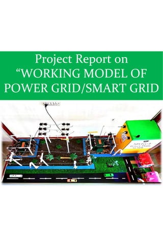
- 32. Project Work: 32
- 33. Conclusion: The distribution substationreceive power from one or more transmission or subtransmission line at the corresponding transmission or sub transmission voltage level and provide tha power to one or more distribution feeders thatoriginate in the substation and comprise the primary network. There is the main component in distribution layout, which is substation, distribution, feeder circuit, protective equipment, distribution transformer, secondary and service. There are five main function of the distribution substation, voltage transformation, switching and protection, voltage regulation and metering. Grid is the nodal point of the entire power system it has two objectives that is 1. Supply power quality 2. Supply the power from source to load with an economic reason. A grid are inter connected so their is an improvement of reliability of cam achievement. As grid is the nodal point if it fail to work then entire power system will fails. As grid has to many equipments so design of costlier. Grid efficiency is lower i.e. 50-70%. Reference: Power System Electrical Machine Internet YouTube 33