SlideShare une entreprise Scribd logo
1  sur  29
Solar Thermal Power Generation
1
Energy from the sun:
• The sun radiates about 3.8 x 1026 W of power in all the directions. Out of this
about 1.7 x 10¹⁷ W is received by earth. The average solar radiation outside the
earth’s atmosphere is 1.35 kW/m2 varying from 1.43 kW/m2 (in January) to 1.33
kW/m2(in July).
• Solar thermal energy (STE) is a form of energy and a technology for harnessing
solar energy to generate thermal energy or electrical energy for use in industry,
and in the residential and commercial sectors. The first installation of solar
thermal energy equipment occurred in the Sahara Desert approximately in 1910.
2
Essential subsystems in a solar energy plant:
1. Solar collector or concentrator:
2. Energy transport medium:
3. Energy storage:
4. Energy conversion plant:
5. Power conditioning, control and protection system:
6. Alternative or standby power supply:
3
Fig: Schematic of a solar thermal conversion system
Solar Thermal Power Generation
• A solar thermal collector system gathers the heat from the solar radiation and gives it to
the heat transport fluid.
• The heat-transport fluid receives the heat from the collector and delivers it to the thermal
storage tank, boiler steam generator, heat exchanger etc.
• Thermal storage system stores heat for a few hours. The heat is released during cloudy
hours and at night.
• Thermal-electric conversion system receives thermal energy and drives steam turbine
generator or gas turbine generator.
• The electrical energy is supplied to the electrical load or to the AC grid. Applications of
solar thermal energy systems range from simple solar cooker of 1 kW rating to complex
solar central receiver thermal power plant of 200 MW rating
4
1. Solar collector or concentrator
• A solar collector is a device that absorbs solar radiation and transforms it
into electricity or heat energy. The materials used in solar collectors vary
in order to maximise the absorption of solar energy.
• There are two main types of solar collectors :
• (A) Flat plate collectors.
• (B) Concentrating collectors. (Generally used for Power Generation
Plants)
• Parabolic trough concentrator
• Parabolic dish concentrator :
• Fresnel lens concentrator:
• Heliostats with centre receiver focusing
5
Classification based on Temp. Range
• Classified by the United States Energy Information Administration as low-,
medium-, or high-temperature collectors.
 Low-temperature collectors are flat plates generally used to heat swimming
pools. (<150oC),
 Medium-temperature collectors are also usually flat plates but are used for
heating water or air for residential and commercial use. (150-300oC)
 High-temperature collectors concentrate sunlight using mirrors or lenses and
are generally used for fulfilling heat requirements above 300oC
2. Energy transport medium: Substances such as water/ steam,
liquid metal or gas are used to transport the thermal energy from the collector to the
heat exchanger or thermal storage. In solar PV systems energy transport occurs in
electrical form.
6
3. Energy storage: Solar energy is not available continuously. So we
need an energy storage medium for maintaining power supply during nights or
cloudy periods. There are three major types of energy storage:
• a) Thermal energy storage;
• b) Battery storage;
• c) Pumped storage hydro-electric plant.
4. Energy conversion plant: Thermal energy collected by solar
collectors is used for producing steam, hot water, etc. Solar energy converted to
thermal energy is fed to steam-thermal or gas-thermal power plant.
7
5. Power conditioning, control and protection
system: Load requirements of electrical energy vary with time. The
energy supply has certain specifications like voltage, current, frequency,
power etc.
• The power conditioning unit performs several functions such as
control, regulation, conditioning, protection, automation, etc.
6. Alternative or standby power supply: The backup may
be obtained as power from electrical network or standby diesel
generator.
8
(A) Flat plate collector
• Absorber plate with number of tubes is prepared by copper tubes and sheets by
soldering.
• This plate is layered by black paint so as to absorb and retain sunlight heat.
• In order to prevent heat losses it is enclosed in box which has insulation on
bottom side and transparent cover on the top side.
• This complete assembly is placed at proper Inclined angle to absorb solar
radiations.
9
• Fluid, water, oil is circulated through
tubes which carry heat to heat
exchanger
• Flat plate collectors are used for small
works, used for temp below 100oC
Advantages of flat plate collectors :
• Construction is very simple.
• Cost is low.
• Maintenance is less.
• Suitable for direct and diffused solar radiations.
• Disadvantages of flat plate collectors :
• Suitable for only low temperature works (upto 100°C) like water
heater, space heater.
• Not suitable for large capacity power generation.
• Weight is much more.
• Dirt, dust, moisture deposits an glass surface so to be cleaned.
• These are at fixed position so loose solar collection.
10
Different factors affecting the performance of system are:
(a) Incident Solar Radiation: The efficiency of collector is directly related with solar radiation
falling on it and increases with rise in temperature.
(b) Number of Cover Plate: The increase in number of cover plate reduces the internal convective
heat losses but also prevents the transmission of radiation inside the collector. More than two cover
plate should not be used to optimize the system.
(c) Spacing: The more space between the absorber and cover plate the less internal heat losses. The
collector efficiency will be increased. However, on the other hand, increase in space between them
provides the shading by side wall in the morning and evening and reduces the absorbed solar flux by
2-3% of system. The spacing between absorber and cover plate is kept 2-3 cm to balance the
problem.
(d) Collector Tilt: The flat plate collectors do not track the sun and should be tilted at angle of
latitude of the location for an average better performance. However, with changing declination angle
with seasons the optimum tilt angle is kept Φ±15o. The collector is placed with south facing at
northern hemisphere to receive maximum radiation throughout the day.
11
(e) Selective Surface: Some materials like nickel black absorptivity and emissivity (α= 0.89, ε= 0.15)
and black chrome (α= 0.87, ε= 0.088), copper oxide (α= 0.89, ε= 0.17) etc. are applied chemically on
the surface of absorber in a thin layer of thickness 0.1 μm.
These chemicals have high degree of absorption (α) to short wave radiation (< 4 μm) and low emission
(ε) of long wave radiations (> 4 μm).
The higher absorption of solar energy increases the temperature of absorber plate and working fluid.
The top losses reduce and the efficiency of the collector increases. The selective surface should be able
to withstand high temperature of 300-400oC, cost less, should not oxidize and be corrosive resistant.
The property of material should not change with time.
(f) Inlet Temperature: With increase in inlet temperature of working fluid the losses increase to
ambient. The high temperature fluid absorbed the less heat from absorber plate because of low
temperature difference and increases the top loss coefficient. Therefore, the efficiency of collector get
reduced with rise in inlet temperature.
(g) Dust on cover Plate: The efficiency of collector decreases with dust particles on the cover plate
because the transmission radiation decreases by 1%. Frequent cleaning is required to get the maximum
efficiency of collector.
12
(B) Concentrating collectors.
• Concentrating collector is a device to collect solar energy with high intensity of
solar radiation on the energy absorbing surface. Such collectors use optical system
in the form of reflectors or refractors.
 It consists of a concentrating devices which may be reflecting mirror or Fresnel
lens and a absorber tube.
 The beam radiation are concentrated and focused on the absorber.
 The size of the absorber can be reduced that gives high concentration ratio.
 Concentration ratio =Aa/Ar
where, Aa= Aperture area of te concentrator Ar= Area of absorber or Area of
receiver
 Different types of collector have different value of concentration ration.
Concentration ratio = 1 for Flat plate collector.
13
Advantages of concentrating collector
 The efficiency increases at high temperatures.
 Thermal losses are less than FPC. However small losses occur in the concentrating collector
because of its optical system as well as by reflection, absorption by mirrors and lenses.
 In these collectors the area intercepting the solar radiation is greater than the absorber area.
 These collectors are used for medium and high-temperature applications.
 Reflectors can cost less per unit area than flat plate collectors.
 Focusing or concentrating systems can be used for electric power generation when not used for
heating or cooling
 Little or no anti freeze is required to protect the absorber in a concentrator system whereas the
entire solar energy collection surface requires anti freeze protection in a flat plate collector.
14
Disadvantages concentrating collector
 Out of the beam and diffuse solar radiation components, only beam component
is collected in case of focusing collectors because diffuse component cannot be
reflected and is thus lost.
 In some stationary reflecting systems it is necessary to have a small absorber to
track the sun image; in others the reflector may have to be adjustable more than
one position if year round operation is desired; in other words costly orienting
systems have to be used to track the sun.
 Additional requirements of maintenance particular to retain the quality of
reflecting surface against dirt, weather, oxidation etc.
 Non –uniform flux on the absorber whereas flux in flat-plate collectors is
uniform.
 Additional optical losses such as reflectance loss and the intercept loss, so they
introduce additional factors in energy balances.
 High initial cost.
15
Parabolic Trough Concentrator
• The most cost effective and widely used systems for generating
electricity in the world.
• Parabolic trough is a set of concave mirrors that concentrate
solar rays on the receiver tube that is located in the focal axis.
• These troughs can track the Sun around one axis, typically
oriented north–south to ensure the highest possible efficiency.
• The fluid flows through this tube and absorbs heat from
the concentrated solar energy.
• Parabolic trough reflectors can achieve a concentration ratio of
30 to 100.
• PTCs are suitable for heating between 100 and 250°C
temperature.
• It is line focus collectors which are extremely powerful solar
collector types. 16
Cont…
• They are used for producing steam for large solar thermal power
plants and not for domestic purposes.
• There is a pipe in the centre of this trough that functions as a carrier of
water.
• The sunlight gathered by the reflective material is focused onto this
central pipe which leads to the heating of the water.
• The first parabolic trough systems were installed in 1912 in Egypt for
powering an irrigation system. The capacity of this facility was 500
KW.
• Most of the plants in operation are located in Spain with 1000 MW.
• 50 MW large-scale grid connected solar thermal power project in
Jaisalmer district, Rajasthan, India. Completed in 2013
17
Parabolic Trough Concentrator Power
Plant
• Ff
18
Parabolic dish concentrator :
• It has point focus collector in parabolic shape in dish
form. This reflects solar radiations on the receiver
mounted at focal point.
• It has approx. 6-7 m diameter paraboloidal dish.
• Highest concentration ratio is obtained in such
construction. This is flexible and efficient type.
• Concentration ratio typically is in the range between 500
to 3000 These systems are very bulky and high-cost
device.
• It is a point-focus system with a paraboloid geometry
• Suitable for high temperature applications.
19
Parabolic dish Power Plant systems
• A parabolic dish system is composed of a large solar light
reflector, a parabolic receiver and a Stirling engine, and a
power generator.
• Parabolic dish systems use mirrors that are mounted over a
parabolic-shaped dish to focus the sun's rays onto a
receiver.
• The receiver is mounted at the focal point of the dish along
with a heat engine (Stirling or Brayton cycle engine),
which has thin tubes inside it. The tubes contain a gas, such
as helium or hydrogen, or even air.
• The hot gas inside the heat engine tubes expands inside
the cylinders and drives their pistons, which then turn
a crankshaft that drives an electric generator producing
electricity.
20
Fresnel lens concentrator
• It has thin and long mirror segments. These segments focus solar
radiations on receiver at a common focal point. Onward journey of
this heat is to the heat exchanger for further steps such as turbine
generator unit.
• This type has better efficiency and higher temperature.
• It has energy storage system. But Its cost is very high and requires
maintenance.
21
Central Tower Receiver Using Heliostat Mirrors
• In case of central tower receiver collector, the receiver is
located at the top of the tower. The system is equivalent to a
very large paraboloidal reflector.
• It has large number of mirrors spread over a large area on the
ground to focus the reflected solar radiation on to a receiver
mounted on a tower. Each mirror used is called the heliostat.
• The mirrors are installed all around the central tower. The
schematic diagram of such a system is shown in Figure.
• Each heliostat is rotated into two directions so as to track the
sun. Heliostats together behave like a broken very large
paraboloidal reflector.
22
Cont…
• The solar radiations so reflected from heliostats are received by the receiver
mounted on a high tower. A concentration ratio upto 3000 can be achieved with
this type of system.
• It can generate directly the high pressure and high temperature of steam suitable
for power generation in steam power plants. Alternately, the receiver can heat a
liquid metal or a molten salt and this heat energy of the fluid can be used in a heat
exchanger for generation of steam which can be used in a Rankine cycle for
electric power generation.
• The design of such system is quite complicated and costly. It is estimated that the
present cost of power generation is about Rs 5.6 crores per MW.
23
• dd
24
Linear Fresnel reflectors
• Linear Fresnel reflector (LFR) systems are similar to parabolic trough systems in that
mirrors (reflectors) concentrate sunlight onto a receiver located above the mirrors.
• These reflectors use the Fresnel lens effect, which allows for a concentrating mirror with
a large aperture and short focal length.
• These systems are capable of concentrating the sun's energy to approximately 30 times
its normal intensity. Compact linear Fresnel reflectors (CLFR)—also referred to as
concentrating linear Fresnel reflectors—are a type of LFR technology that has multiple
absorbers within the vicinity of the mirrors. Multiple receivers allow the mirrors to
change their inclination to minimize how much they block adjacent reflectors' access to
sunlight. This positioning improves system efficiency and reduces material requirements
and costs. A demonstration CLFR solar power plant was built near Bakersfield, California,
in 2008, but it is currently not operational.
•
25
SOLAR POND
• A solar pond is also another type of solar collector
which is used for applications where large
temperatures are not necessary.
• It may be used for generating heat or electricity or for
desalination of water or for low temperature
applications in industry and agriculture.
• It works on a simple phenomenon. When water heats
up a pond or lake, water rises up after getting warmed.
• In a solar pond, heat is trapped because salt is added,
the concentration increasing with depth. Because of
being heavy, it cannot rise and the heat generated by
sunshine remains trapped.
• The temperature at the bottom of the pond will rise to
over 90 °C while the temperature at the top of the
pond is usually around 30 °C
26
Solar pond schematic
• There are 3 distinct layers of water in the pond:
1. The top zone or the surface zone is called the UCZ (Upper Convective Zone) and is
atmospheric temperature. It has little salt content.
2. The bottom zone is the hot zone also called the LCZ (Lower Convective Zone).
Temperatures in the range of 70°– 85° C. It has a high concentration of salt. It energy in the
form of heat.
3. The zone of separation is called NCZ (Non-Convective Zone). The salt content increases in
this zone as the depth increases. Water in a particular layer cannot rise as the water above it is
lighter due to lower salt content and vice versa. The salt gradient also acts as an insulator
trapping the sunlight.
• The energy obtained is rather low grade and can generate temperatures in the range of 70-80 °C.
However, larger systems can be built using no more than a membrane to cover the pond which
results in much lower costs.
• Usually, coastal locations are good locations for such solar ponds although theoretically they can
be constructed anywhere.
27
• ff
28
Cont..
• The energy obtained is rather low grade and can generate temperatures in the range of
70-80 °C. However, larger systems can be built using no more than a membrane to cover
the pond which results in much lower costs. Usually, coastal locations are good locations
for such solar ponds although theoretically they can be constructed anywhere.
• Advantages:
• Highly useful for rural areas because of the low cost involved.
• A separate collector system is not needed in a solar pond setup.
• The heat stored is on a very large scale and hence it can be used day and night, no storage
is necessary in the form of batteries.
• Disadvantages:
• Larger land area requirement is often a deterrent.
• The surface water keeps evaporating and needs to be replaced periodically.
• Large supply of salt water is needed.
• Some degree of maintenance is necessary- removing and preventing algae growth;
maintain transparency in the pond and the salt gradient.
29

Contenu connexe

Similaire à Generate Power from the Sun with Solar Thermal

3 solar energy collector
3 solar energy collector3 solar energy collector
3 solar energy collectorMd Irfan Ansari
 
Solar Calculation (44 slide)
 Solar Calculation (44 slide) Solar Calculation (44 slide)
Solar Calculation (44 slide)Rami Hassbini
 
Types of Solar Thermal generation Technology
Types of Solar Thermal generation TechnologyTypes of Solar Thermal generation Technology
Types of Solar Thermal generation Technologyprofabhishekranjan
 
basic renewable energy for Engineering Students
basic renewable energy for Engineering Studentsbasic renewable energy for Engineering Students
basic renewable energy for Engineering Studentspankajnavale25
 
Solar Energy Capture Transform Store Utilize
Solar Energy Capture Transform Store UtilizeSolar Energy Capture Transform Store Utilize
Solar Energy Capture Transform Store UtilizeH Janardan Prabhu
 
Solar Thermal in power generation for cleaner
Solar Thermal in power generation for cleanerSolar Thermal in power generation for cleaner
Solar Thermal in power generation for cleanerHWNoorShieela1
 
Chapter 12 Solar Energy.pdf
Chapter 12 Solar Energy.pdfChapter 12 Solar Energy.pdf
Chapter 12 Solar Energy.pdfAkramMusa5
 
Solar energy collectors
Solar energy collectorsSolar energy collectors
Solar energy collectorsKanav Sinhmar
 
ppt-180619043752 (1).pdf
ppt-180619043752 (1).pdfppt-180619043752 (1).pdf
ppt-180619043752 (1).pdfGuddubk
 
Solar Thermal Engineeirng chap 3.pdf
Solar Thermal Engineeirng  chap 3.pdfSolar Thermal Engineeirng  chap 3.pdf
Solar Thermal Engineeirng chap 3.pdfsolomon261775
 
Desalination 2004 cm
Desalination 2004 cmDesalination 2004 cm
Desalination 2004 cmJuan Baldez
 
Flat plate collectors.pptx
Flat plate collectors.pptxFlat plate collectors.pptx
Flat plate collectors.pptxAmanKumar268236
 
Presentation 3 (1) - Copy.pptx
Presentation 3 (1) - Copy.pptxPresentation 3 (1) - Copy.pptx
Presentation 3 (1) - Copy.pptxAshaShinde12
 

Similaire à Generate Power from the Sun with Solar Thermal (20)

3 solar energy collector
3 solar energy collector3 solar energy collector
3 solar energy collector
 
Solar power plant
Solar power plantSolar power plant
Solar power plant
 
Solar Calculation (44 slide)
 Solar Calculation (44 slide) Solar Calculation (44 slide)
Solar Calculation (44 slide)
 
Solar energy
Solar energySolar energy
Solar energy
 
Types of Solar Thermal generation Technology
Types of Solar Thermal generation TechnologyTypes of Solar Thermal generation Technology
Types of Solar Thermal generation Technology
 
Solar Energy -2.docx
Solar Energy -2.docxSolar Energy -2.docx
Solar Energy -2.docx
 
basic renewable energy for Engineering Students
basic renewable energy for Engineering Studentsbasic renewable energy for Engineering Students
basic renewable energy for Engineering Students
 
Solar turbine plants
Solar turbine plantsSolar turbine plants
Solar turbine plants
 
Solar Energy Capture Transform Store Utilize
Solar Energy Capture Transform Store UtilizeSolar Energy Capture Transform Store Utilize
Solar Energy Capture Transform Store Utilize
 
Solar Thermal in power generation for cleaner
Solar Thermal in power generation for cleanerSolar Thermal in power generation for cleaner
Solar Thermal in power generation for cleaner
 
Unit 2-REGS.ppt
Unit 2-REGS.pptUnit 2-REGS.ppt
Unit 2-REGS.ppt
 
Module 2.pdf
Module 2.pdfModule 2.pdf
Module 2.pdf
 
Chapter 12 Solar Energy.pdf
Chapter 12 Solar Energy.pdfChapter 12 Solar Energy.pdf
Chapter 12 Solar Energy.pdf
 
Solar energy collectors
Solar energy collectorsSolar energy collectors
Solar energy collectors
 
ppt-180619043752 (1).pdf
ppt-180619043752 (1).pdfppt-180619043752 (1).pdf
ppt-180619043752 (1).pdf
 
Solar Thermal Engineeirng chap 3.pdf
Solar Thermal Engineeirng  chap 3.pdfSolar Thermal Engineeirng  chap 3.pdf
Solar Thermal Engineeirng chap 3.pdf
 
Desalination 2004 cm
Desalination 2004 cmDesalination 2004 cm
Desalination 2004 cm
 
Flate plate collector
Flate plate collectorFlate plate collector
Flate plate collector
 
Flat plate collectors.pptx
Flat plate collectors.pptxFlat plate collectors.pptx
Flat plate collectors.pptx
 
Presentation 3 (1) - Copy.pptx
Presentation 3 (1) - Copy.pptxPresentation 3 (1) - Copy.pptx
Presentation 3 (1) - Copy.pptx
 

Dernier

Input Output Management in Operating System
Input Output Management in Operating SystemInput Output Management in Operating System
Input Output Management in Operating SystemRashmi Bhat
 
Research Methodology for Engineering pdf
Research Methodology for Engineering pdfResearch Methodology for Engineering pdf
Research Methodology for Engineering pdfCaalaaAbdulkerim
 
An experimental study in using natural admixture as an alternative for chemic...
An experimental study in using natural admixture as an alternative for chemic...An experimental study in using natural admixture as an alternative for chemic...
An experimental study in using natural admixture as an alternative for chemic...Chandu841456
 
Mine Environment II Lab_MI10448MI__________.pptx
Mine Environment II Lab_MI10448MI__________.pptxMine Environment II Lab_MI10448MI__________.pptx
Mine Environment II Lab_MI10448MI__________.pptxRomil Mishra
 
Earthing details of Electrical Substation
Earthing details of Electrical SubstationEarthing details of Electrical Substation
Earthing details of Electrical Substationstephanwindworld
 
Vishratwadi & Ghorpadi Bridge Tender documents
Vishratwadi & Ghorpadi Bridge Tender documentsVishratwadi & Ghorpadi Bridge Tender documents
Vishratwadi & Ghorpadi Bridge Tender documentsSachinPawar510423
 
Steel Structures - Building technology.pptx
Steel Structures - Building technology.pptxSteel Structures - Building technology.pptx
Steel Structures - Building technology.pptxNikhil Raut
 
Introduction to Machine Learning Unit-3 for II MECH
Introduction to Machine Learning Unit-3 for II MECHIntroduction to Machine Learning Unit-3 for II MECH
Introduction to Machine Learning Unit-3 for II MECHC Sai Kiran
 
IVE Industry Focused Event - Defence Sector 2024
IVE Industry Focused Event - Defence Sector 2024IVE Industry Focused Event - Defence Sector 2024
IVE Industry Focused Event - Defence Sector 2024Mark Billinghurst
 
Industrial Safety Unit-I SAFETY TERMINOLOGIES
Industrial Safety Unit-I SAFETY TERMINOLOGIESIndustrial Safety Unit-I SAFETY TERMINOLOGIES
Industrial Safety Unit-I SAFETY TERMINOLOGIESNarmatha D
 
welding defects observed during the welding
welding defects observed during the weldingwelding defects observed during the welding
welding defects observed during the weldingMuhammadUzairLiaqat
 
National Level Hackathon Participation Certificate.pdf
National Level Hackathon Participation Certificate.pdfNational Level Hackathon Participation Certificate.pdf
National Level Hackathon Participation Certificate.pdfRajuKanojiya4
 
UNIT III ANALOG ELECTRONICS (BASIC ELECTRONICS)
UNIT III ANALOG ELECTRONICS (BASIC ELECTRONICS)UNIT III ANALOG ELECTRONICS (BASIC ELECTRONICS)
UNIT III ANALOG ELECTRONICS (BASIC ELECTRONICS)Dr SOUNDIRARAJ N
 
Software and Systems Engineering Standards: Verification and Validation of Sy...
Software and Systems Engineering Standards: Verification and Validation of Sy...Software and Systems Engineering Standards: Verification and Validation of Sy...
Software and Systems Engineering Standards: Verification and Validation of Sy...VICTOR MAESTRE RAMIREZ
 
The SRE Report 2024 - Great Findings for the teams
The SRE Report 2024 - Great Findings for the teamsThe SRE Report 2024 - Great Findings for the teams
The SRE Report 2024 - Great Findings for the teamsDILIPKUMARMONDAL6
 
US Department of Education FAFSA Week of Action
US Department of Education FAFSA Week of ActionUS Department of Education FAFSA Week of Action
US Department of Education FAFSA Week of ActionMebane Rash
 
Risk Assessment For Installation of Drainage Pipes.pdf
Risk Assessment For Installation of Drainage Pipes.pdfRisk Assessment For Installation of Drainage Pipes.pdf
Risk Assessment For Installation of Drainage Pipes.pdfROCENODodongVILLACER
 
Work Experience-Dalton Park.pptxfvvvvvvv
Work Experience-Dalton Park.pptxfvvvvvvvWork Experience-Dalton Park.pptxfvvvvvvv
Work Experience-Dalton Park.pptxfvvvvvvvLewisJB
 

Dernier (20)

Input Output Management in Operating System
Input Output Management in Operating SystemInput Output Management in Operating System
Input Output Management in Operating System
 
Research Methodology for Engineering pdf
Research Methodology for Engineering pdfResearch Methodology for Engineering pdf
Research Methodology for Engineering pdf
 
🔝9953056974🔝!!-YOUNG call girls in Rajendra Nagar Escort rvice Shot 2000 nigh...
🔝9953056974🔝!!-YOUNG call girls in Rajendra Nagar Escort rvice Shot 2000 nigh...🔝9953056974🔝!!-YOUNG call girls in Rajendra Nagar Escort rvice Shot 2000 nigh...
🔝9953056974🔝!!-YOUNG call girls in Rajendra Nagar Escort rvice Shot 2000 nigh...
 
An experimental study in using natural admixture as an alternative for chemic...
An experimental study in using natural admixture as an alternative for chemic...An experimental study in using natural admixture as an alternative for chemic...
An experimental study in using natural admixture as an alternative for chemic...
 
young call girls in Green Park🔝 9953056974 🔝 escort Service
young call girls in Green Park🔝 9953056974 🔝 escort Serviceyoung call girls in Green Park🔝 9953056974 🔝 escort Service
young call girls in Green Park🔝 9953056974 🔝 escort Service
 
Mine Environment II Lab_MI10448MI__________.pptx
Mine Environment II Lab_MI10448MI__________.pptxMine Environment II Lab_MI10448MI__________.pptx
Mine Environment II Lab_MI10448MI__________.pptx
 
Earthing details of Electrical Substation
Earthing details of Electrical SubstationEarthing details of Electrical Substation
Earthing details of Electrical Substation
 
Vishratwadi & Ghorpadi Bridge Tender documents
Vishratwadi & Ghorpadi Bridge Tender documentsVishratwadi & Ghorpadi Bridge Tender documents
Vishratwadi & Ghorpadi Bridge Tender documents
 
Steel Structures - Building technology.pptx
Steel Structures - Building technology.pptxSteel Structures - Building technology.pptx
Steel Structures - Building technology.pptx
 
Introduction to Machine Learning Unit-3 for II MECH
Introduction to Machine Learning Unit-3 for II MECHIntroduction to Machine Learning Unit-3 for II MECH
Introduction to Machine Learning Unit-3 for II MECH
 
IVE Industry Focused Event - Defence Sector 2024
IVE Industry Focused Event - Defence Sector 2024IVE Industry Focused Event - Defence Sector 2024
IVE Industry Focused Event - Defence Sector 2024
 
Industrial Safety Unit-I SAFETY TERMINOLOGIES
Industrial Safety Unit-I SAFETY TERMINOLOGIESIndustrial Safety Unit-I SAFETY TERMINOLOGIES
Industrial Safety Unit-I SAFETY TERMINOLOGIES
 
welding defects observed during the welding
welding defects observed during the weldingwelding defects observed during the welding
welding defects observed during the welding
 
National Level Hackathon Participation Certificate.pdf
National Level Hackathon Participation Certificate.pdfNational Level Hackathon Participation Certificate.pdf
National Level Hackathon Participation Certificate.pdf
 
UNIT III ANALOG ELECTRONICS (BASIC ELECTRONICS)
UNIT III ANALOG ELECTRONICS (BASIC ELECTRONICS)UNIT III ANALOG ELECTRONICS (BASIC ELECTRONICS)
UNIT III ANALOG ELECTRONICS (BASIC ELECTRONICS)
 
Software and Systems Engineering Standards: Verification and Validation of Sy...
Software and Systems Engineering Standards: Verification and Validation of Sy...Software and Systems Engineering Standards: Verification and Validation of Sy...
Software and Systems Engineering Standards: Verification and Validation of Sy...
 
The SRE Report 2024 - Great Findings for the teams
The SRE Report 2024 - Great Findings for the teamsThe SRE Report 2024 - Great Findings for the teams
The SRE Report 2024 - Great Findings for the teams
 
US Department of Education FAFSA Week of Action
US Department of Education FAFSA Week of ActionUS Department of Education FAFSA Week of Action
US Department of Education FAFSA Week of Action
 
Risk Assessment For Installation of Drainage Pipes.pdf
Risk Assessment For Installation of Drainage Pipes.pdfRisk Assessment For Installation of Drainage Pipes.pdf
Risk Assessment For Installation of Drainage Pipes.pdf
 
Work Experience-Dalton Park.pptxfvvvvvvv
Work Experience-Dalton Park.pptxfvvvvvvvWork Experience-Dalton Park.pptxfvvvvvvv
Work Experience-Dalton Park.pptxfvvvvvvv
 

Generate Power from the Sun with Solar Thermal

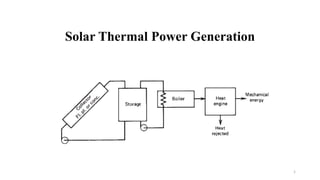
  • 1. Solar Thermal Power Generation 1
  • 2. Energy from the sun: • The sun radiates about 3.8 x 1026 W of power in all the directions. Out of this about 1.7 x 10¹⁷ W is received by earth. The average solar radiation outside the earth’s atmosphere is 1.35 kW/m2 varying from 1.43 kW/m2 (in January) to 1.33 kW/m2(in July). • Solar thermal energy (STE) is a form of energy and a technology for harnessing solar energy to generate thermal energy or electrical energy for use in industry, and in the residential and commercial sectors. The first installation of solar thermal energy equipment occurred in the Sahara Desert approximately in 1910. 2
  • 3. Essential subsystems in a solar energy plant: 1. Solar collector or concentrator: 2. Energy transport medium: 3. Energy storage: 4. Energy conversion plant: 5. Power conditioning, control and protection system: 6. Alternative or standby power supply: 3 Fig: Schematic of a solar thermal conversion system
  • 4. Solar Thermal Power Generation • A solar thermal collector system gathers the heat from the solar radiation and gives it to the heat transport fluid. • The heat-transport fluid receives the heat from the collector and delivers it to the thermal storage tank, boiler steam generator, heat exchanger etc. • Thermal storage system stores heat for a few hours. The heat is released during cloudy hours and at night. • Thermal-electric conversion system receives thermal energy and drives steam turbine generator or gas turbine generator. • The electrical energy is supplied to the electrical load or to the AC grid. Applications of solar thermal energy systems range from simple solar cooker of 1 kW rating to complex solar central receiver thermal power plant of 200 MW rating 4
  • 5. 1. Solar collector or concentrator • A solar collector is a device that absorbs solar radiation and transforms it into electricity or heat energy. The materials used in solar collectors vary in order to maximise the absorption of solar energy. • There are two main types of solar collectors : • (A) Flat plate collectors. • (B) Concentrating collectors. (Generally used for Power Generation Plants) • Parabolic trough concentrator • Parabolic dish concentrator : • Fresnel lens concentrator: • Heliostats with centre receiver focusing 5
  • 6. Classification based on Temp. Range • Classified by the United States Energy Information Administration as low-, medium-, or high-temperature collectors.  Low-temperature collectors are flat plates generally used to heat swimming pools. (<150oC),  Medium-temperature collectors are also usually flat plates but are used for heating water or air for residential and commercial use. (150-300oC)  High-temperature collectors concentrate sunlight using mirrors or lenses and are generally used for fulfilling heat requirements above 300oC 2. Energy transport medium: Substances such as water/ steam, liquid metal or gas are used to transport the thermal energy from the collector to the heat exchanger or thermal storage. In solar PV systems energy transport occurs in electrical form. 6
  • 7. 3. Energy storage: Solar energy is not available continuously. So we need an energy storage medium for maintaining power supply during nights or cloudy periods. There are three major types of energy storage: • a) Thermal energy storage; • b) Battery storage; • c) Pumped storage hydro-electric plant. 4. Energy conversion plant: Thermal energy collected by solar collectors is used for producing steam, hot water, etc. Solar energy converted to thermal energy is fed to steam-thermal or gas-thermal power plant. 7
  • 8. 5. Power conditioning, control and protection system: Load requirements of electrical energy vary with time. The energy supply has certain specifications like voltage, current, frequency, power etc. • The power conditioning unit performs several functions such as control, regulation, conditioning, protection, automation, etc. 6. Alternative or standby power supply: The backup may be obtained as power from electrical network or standby diesel generator. 8
  • 9. (A) Flat plate collector • Absorber plate with number of tubes is prepared by copper tubes and sheets by soldering. • This plate is layered by black paint so as to absorb and retain sunlight heat. • In order to prevent heat losses it is enclosed in box which has insulation on bottom side and transparent cover on the top side. • This complete assembly is placed at proper Inclined angle to absorb solar radiations. 9 • Fluid, water, oil is circulated through tubes which carry heat to heat exchanger • Flat plate collectors are used for small works, used for temp below 100oC
  • 10. Advantages of flat plate collectors : • Construction is very simple. • Cost is low. • Maintenance is less. • Suitable for direct and diffused solar radiations. • Disadvantages of flat plate collectors : • Suitable for only low temperature works (upto 100°C) like water heater, space heater. • Not suitable for large capacity power generation. • Weight is much more. • Dirt, dust, moisture deposits an glass surface so to be cleaned. • These are at fixed position so loose solar collection. 10
  • 11. Different factors affecting the performance of system are: (a) Incident Solar Radiation: The efficiency of collector is directly related with solar radiation falling on it and increases with rise in temperature. (b) Number of Cover Plate: The increase in number of cover plate reduces the internal convective heat losses but also prevents the transmission of radiation inside the collector. More than two cover plate should not be used to optimize the system. (c) Spacing: The more space between the absorber and cover plate the less internal heat losses. The collector efficiency will be increased. However, on the other hand, increase in space between them provides the shading by side wall in the morning and evening and reduces the absorbed solar flux by 2-3% of system. The spacing between absorber and cover plate is kept 2-3 cm to balance the problem. (d) Collector Tilt: The flat plate collectors do not track the sun and should be tilted at angle of latitude of the location for an average better performance. However, with changing declination angle with seasons the optimum tilt angle is kept Φ±15o. The collector is placed with south facing at northern hemisphere to receive maximum radiation throughout the day. 11
  • 12. (e) Selective Surface: Some materials like nickel black absorptivity and emissivity (α= 0.89, ε= 0.15) and black chrome (α= 0.87, ε= 0.088), copper oxide (α= 0.89, ε= 0.17) etc. are applied chemically on the surface of absorber in a thin layer of thickness 0.1 μm. These chemicals have high degree of absorption (α) to short wave radiation (< 4 μm) and low emission (ε) of long wave radiations (> 4 μm). The higher absorption of solar energy increases the temperature of absorber plate and working fluid. The top losses reduce and the efficiency of the collector increases. The selective surface should be able to withstand high temperature of 300-400oC, cost less, should not oxidize and be corrosive resistant. The property of material should not change with time. (f) Inlet Temperature: With increase in inlet temperature of working fluid the losses increase to ambient. The high temperature fluid absorbed the less heat from absorber plate because of low temperature difference and increases the top loss coefficient. Therefore, the efficiency of collector get reduced with rise in inlet temperature. (g) Dust on cover Plate: The efficiency of collector decreases with dust particles on the cover plate because the transmission radiation decreases by 1%. Frequent cleaning is required to get the maximum efficiency of collector. 12
  • 13. (B) Concentrating collectors. • Concentrating collector is a device to collect solar energy with high intensity of solar radiation on the energy absorbing surface. Such collectors use optical system in the form of reflectors or refractors.  It consists of a concentrating devices which may be reflecting mirror or Fresnel lens and a absorber tube.  The beam radiation are concentrated and focused on the absorber.  The size of the absorber can be reduced that gives high concentration ratio.  Concentration ratio =Aa/Ar where, Aa= Aperture area of te concentrator Ar= Area of absorber or Area of receiver  Different types of collector have different value of concentration ration. Concentration ratio = 1 for Flat plate collector. 13
  • 14. Advantages of concentrating collector  The efficiency increases at high temperatures.  Thermal losses are less than FPC. However small losses occur in the concentrating collector because of its optical system as well as by reflection, absorption by mirrors and lenses.  In these collectors the area intercepting the solar radiation is greater than the absorber area.  These collectors are used for medium and high-temperature applications.  Reflectors can cost less per unit area than flat plate collectors.  Focusing or concentrating systems can be used for electric power generation when not used for heating or cooling  Little or no anti freeze is required to protect the absorber in a concentrator system whereas the entire solar energy collection surface requires anti freeze protection in a flat plate collector. 14
  • 15. Disadvantages concentrating collector  Out of the beam and diffuse solar radiation components, only beam component is collected in case of focusing collectors because diffuse component cannot be reflected and is thus lost.  In some stationary reflecting systems it is necessary to have a small absorber to track the sun image; in others the reflector may have to be adjustable more than one position if year round operation is desired; in other words costly orienting systems have to be used to track the sun.  Additional requirements of maintenance particular to retain the quality of reflecting surface against dirt, weather, oxidation etc.  Non –uniform flux on the absorber whereas flux in flat-plate collectors is uniform.  Additional optical losses such as reflectance loss and the intercept loss, so they introduce additional factors in energy balances.  High initial cost. 15
  • 16. Parabolic Trough Concentrator • The most cost effective and widely used systems for generating electricity in the world. • Parabolic trough is a set of concave mirrors that concentrate solar rays on the receiver tube that is located in the focal axis. • These troughs can track the Sun around one axis, typically oriented north–south to ensure the highest possible efficiency. • The fluid flows through this tube and absorbs heat from the concentrated solar energy. • Parabolic trough reflectors can achieve a concentration ratio of 30 to 100. • PTCs are suitable for heating between 100 and 250°C temperature. • It is line focus collectors which are extremely powerful solar collector types. 16
  • 17. Cont… • They are used for producing steam for large solar thermal power plants and not for domestic purposes. • There is a pipe in the centre of this trough that functions as a carrier of water. • The sunlight gathered by the reflective material is focused onto this central pipe which leads to the heating of the water. • The first parabolic trough systems were installed in 1912 in Egypt for powering an irrigation system. The capacity of this facility was 500 KW. • Most of the plants in operation are located in Spain with 1000 MW. • 50 MW large-scale grid connected solar thermal power project in Jaisalmer district, Rajasthan, India. Completed in 2013 17
  • 18. Parabolic Trough Concentrator Power Plant • Ff 18
  • 19. Parabolic dish concentrator : • It has point focus collector in parabolic shape in dish form. This reflects solar radiations on the receiver mounted at focal point. • It has approx. 6-7 m diameter paraboloidal dish. • Highest concentration ratio is obtained in such construction. This is flexible and efficient type. • Concentration ratio typically is in the range between 500 to 3000 These systems are very bulky and high-cost device. • It is a point-focus system with a paraboloid geometry • Suitable for high temperature applications. 19
  • 20. Parabolic dish Power Plant systems • A parabolic dish system is composed of a large solar light reflector, a parabolic receiver and a Stirling engine, and a power generator. • Parabolic dish systems use mirrors that are mounted over a parabolic-shaped dish to focus the sun's rays onto a receiver. • The receiver is mounted at the focal point of the dish along with a heat engine (Stirling or Brayton cycle engine), which has thin tubes inside it. The tubes contain a gas, such as helium or hydrogen, or even air. • The hot gas inside the heat engine tubes expands inside the cylinders and drives their pistons, which then turn a crankshaft that drives an electric generator producing electricity. 20
  • 21. Fresnel lens concentrator • It has thin and long mirror segments. These segments focus solar radiations on receiver at a common focal point. Onward journey of this heat is to the heat exchanger for further steps such as turbine generator unit. • This type has better efficiency and higher temperature. • It has energy storage system. But Its cost is very high and requires maintenance. 21
  • 22. Central Tower Receiver Using Heliostat Mirrors • In case of central tower receiver collector, the receiver is located at the top of the tower. The system is equivalent to a very large paraboloidal reflector. • It has large number of mirrors spread over a large area on the ground to focus the reflected solar radiation on to a receiver mounted on a tower. Each mirror used is called the heliostat. • The mirrors are installed all around the central tower. The schematic diagram of such a system is shown in Figure. • Each heliostat is rotated into two directions so as to track the sun. Heliostats together behave like a broken very large paraboloidal reflector. 22
  • 23. Cont… • The solar radiations so reflected from heliostats are received by the receiver mounted on a high tower. A concentration ratio upto 3000 can be achieved with this type of system. • It can generate directly the high pressure and high temperature of steam suitable for power generation in steam power plants. Alternately, the receiver can heat a liquid metal or a molten salt and this heat energy of the fluid can be used in a heat exchanger for generation of steam which can be used in a Rankine cycle for electric power generation. • The design of such system is quite complicated and costly. It is estimated that the present cost of power generation is about Rs 5.6 crores per MW. 23
  • 25. Linear Fresnel reflectors • Linear Fresnel reflector (LFR) systems are similar to parabolic trough systems in that mirrors (reflectors) concentrate sunlight onto a receiver located above the mirrors. • These reflectors use the Fresnel lens effect, which allows for a concentrating mirror with a large aperture and short focal length. • These systems are capable of concentrating the sun's energy to approximately 30 times its normal intensity. Compact linear Fresnel reflectors (CLFR)—also referred to as concentrating linear Fresnel reflectors—are a type of LFR technology that has multiple absorbers within the vicinity of the mirrors. Multiple receivers allow the mirrors to change their inclination to minimize how much they block adjacent reflectors' access to sunlight. This positioning improves system efficiency and reduces material requirements and costs. A demonstration CLFR solar power plant was built near Bakersfield, California, in 2008, but it is currently not operational. • 25
  • 26. SOLAR POND • A solar pond is also another type of solar collector which is used for applications where large temperatures are not necessary. • It may be used for generating heat or electricity or for desalination of water or for low temperature applications in industry and agriculture. • It works on a simple phenomenon. When water heats up a pond or lake, water rises up after getting warmed. • In a solar pond, heat is trapped because salt is added, the concentration increasing with depth. Because of being heavy, it cannot rise and the heat generated by sunshine remains trapped. • The temperature at the bottom of the pond will rise to over 90 °C while the temperature at the top of the pond is usually around 30 °C 26 Solar pond schematic
  • 27. • There are 3 distinct layers of water in the pond: 1. The top zone or the surface zone is called the UCZ (Upper Convective Zone) and is atmospheric temperature. It has little salt content. 2. The bottom zone is the hot zone also called the LCZ (Lower Convective Zone). Temperatures in the range of 70°– 85° C. It has a high concentration of salt. It energy in the form of heat. 3. The zone of separation is called NCZ (Non-Convective Zone). The salt content increases in this zone as the depth increases. Water in a particular layer cannot rise as the water above it is lighter due to lower salt content and vice versa. The salt gradient also acts as an insulator trapping the sunlight. • The energy obtained is rather low grade and can generate temperatures in the range of 70-80 °C. However, larger systems can be built using no more than a membrane to cover the pond which results in much lower costs. • Usually, coastal locations are good locations for such solar ponds although theoretically they can be constructed anywhere. 27
  • 29. Cont.. • The energy obtained is rather low grade and can generate temperatures in the range of 70-80 °C. However, larger systems can be built using no more than a membrane to cover the pond which results in much lower costs. Usually, coastal locations are good locations for such solar ponds although theoretically they can be constructed anywhere. • Advantages: • Highly useful for rural areas because of the low cost involved. • A separate collector system is not needed in a solar pond setup. • The heat stored is on a very large scale and hence it can be used day and night, no storage is necessary in the form of batteries. • Disadvantages: • Larger land area requirement is often a deterrent. • The surface water keeps evaporating and needs to be replaced periodically. • Large supply of salt water is needed. • Some degree of maintenance is necessary- removing and preventing algae growth; maintain transparency in the pond and the salt gradient. 29