SlideShare a Scribd company logo
1 of 18
Download to read offline
7.Alternating Current
Coaching for 8-10th Page 127
Voltage/current
Voltage/current
Direct current(DC):
time.
Example: Battery, cell, solar cell
Alternating current(AC): The current whose magnitude and direction changes
continuously with time.
Example: Electric generator.
Variation of current/voltage with time for DC and AC shown below
Voltage(emf) and current in the alternating current:
We know that the source of AC is electric generator as we have seen in EMI topic.
The emf developed is given by,
𝜀 = 𝜀𝑜 sin 𝜔𝑡
Hence current in the circuit is also given by ohm’s law if the R be the resistance of the circuit,
𝐼 =
𝜀
𝑅
=
𝜀𝑜 sin 𝜔𝑡
𝑅
Or
𝑰 = 𝑰𝒐 𝐬𝐢𝐧 𝝎𝒕 − − − −𝑇ℎ𝑖𝑠 𝑖𝑠 𝑎𝑛 𝑖𝑛𝑠𝑡𝑎𝑛𝑎𝑛𝑒𝑜𝑢𝑠 𝑐𝑢𝑟𝑟𝑒𝑛𝑡 𝑎𝑡 𝑎𝑛𝑦 𝑡𝑖𝑚𝑒 ′𝑡′
Where,
𝑰𝒐 =
𝜺𝒐
𝑹
− − − 𝑃𝑒𝑎𝑘 𝑜𝑟 𝑚𝑎𝑥𝑖𝑚𝑢𝑚 𝑐𝑢𝑟𝑟𝑒𝑛𝑡 𝑣𝑎𝑙𝑢𝑒 𝑜𝑓 𝐴𝐶
Note: The frequency of an Alternating current in INDIA is 50Hz.
t
t
Direct current Alternating current
, PU I & II (Sci. & Commerce), NTSE, Olympiad, KVPY, NDA, CET, NEET, JEE. Call: 9663320948
The current whose magnitude and direction remain constant with
7.Alternating Current
Coaching for 8-10th Page 128
 Average value of AC over one complete cycle of AC is ZERO.As alternating current is
positive in one half cycle and equally negative in the other half cycle so its mean value
over complete cycle is zero
𝐼 =
𝑞
𝑇
= 𝑜
We cannot measure AC by using simple moving coil galvanometer, it can be
measured by using hot-wire ammeter which is based on heating effect of current.
Different values of Alternating Current
 Mean OR Average value of A.C.- It is that amount of direct current when passed
through a circuit for a half the time period of A.C., it send same amount of charges
through the circuit as sent by the A.C. through same circuit in the same time.
𝑰𝒂𝒗 = 𝑰𝒎 =
𝟐
𝝅
𝑰𝒐 = 𝟎. 𝟔𝟑𝟕 𝑰𝒐
Where, 𝐼𝑜 − 𝑝𝑒𝑎𝑘 𝑣𝑎𝑙𝑢𝑒 𝑜𝑓 𝐴. 𝐶.
Also for emf we can write,
𝜺𝒂𝒗 = 𝜺𝒎 =
𝟐
𝝅
𝜺𝒐 = 𝟎. 𝟔𝟑𝟕 𝜺𝒐
 Root Mean Square(RMS) or Effective value of A.C.- It is that amount of direct current
when passed through a resistor for any duration of time period, produces same
amount of heat in the resistor as it produced by A.C. in the same resistor in the same
time.
𝑰𝒓𝒎𝒔 𝒐𝒓 𝑰𝒆𝒇𝒇 =
𝑰𝒐
√𝟐
= 𝟎. 𝟕𝟎𝟕 𝑰𝒐
Also for emf we can write,
𝜺𝒓𝒎𝒔 𝒐𝒓 𝜺𝒆𝒇𝒇 =
𝜺𝒐
√𝟐
= 𝟎. 𝟕𝟎𝟕 𝜺𝒐
Numerical 1):-A light bulb is rated at 100W for a 220 V supply. Find (a) the resistance of the
bulb; (b) the peak voltage of the source; and (c) the rms current through the bul.
Numerical 2):-A 100 Ω resistor is connected to a 220 V, 50 Hz ac supply. (a) What is the rms
value of current in the circuit? (b) What is the net power consumed over a full cycle?
Numerical 3):-a) The peak voltage of an ac supply is 300 V. What is the rms voltage?
(b) The rms value of current in an ac circuit is 10 A. What is the peak current?
,
7.Alternating Current
Coaching for 8-10th Page 129
PHASOR AND PHASOR DIAGRAM
“A rotating vector that represents a varying physical quantity is called as Phasor.”
The length of the vector represents the magnitude and and its projection on fixed
axis gives the instantaneous value of the quantity
To study the alternating current we have to consider a alternating voltage and
current as rotating phasors.
“Phasor diagram are diagram representing alternating current and voltage of same
frequency as vectors or phasors with the phase angle between them and rotating about the
origin.”
The vertical components of phasors V and I represent the sinusoidally varying
quantities v and i. The angle between the V and I phasor is known as phasor angle or simply
Phase(∅)
AC VOLTAGE APPLIED TO A RESISTOR(R)(3marks)
Let a resistor of resistance R is connected to a source of an alternating emf is
𝜺 = 𝜺𝒐 𝒔𝒊𝒏 𝝎𝒕 − − − −(𝟏)
Let I be the current in the circuit at any instant of time t , then potential across resistor is
given by ohm’s law,
𝐼 =
𝜀
𝑅
=
𝜀𝑜 sin 𝜔𝑡
𝑅
𝑰 = 𝑰𝒐 𝒔𝒊𝒏 𝝎𝒕 − − − −(𝟐) (∵ 𝑰𝒐 =
𝜺𝒐
𝑹
)
Comparing equation (1) and (2) , Current I and the voltage(emf) 𝜺 both are in the same
phase. This means that both I and 𝜺 attains the maximum, minimum and zero at the same
time. The phasor diagram for purely resistive circuit is shown in below diagram.
The phase angle between the current I and 𝜀 is zero. i.e. (∅ = 0𝑜
)(1mark)
,
7.Alternating Current
Coaching for 8-10th Page 130
AC VOLTAGE APPLIED TO A INDUCTOR(L)(3marks)
Let an Inductor, L is connected to source of alternating current , 𝜀 as shown in fig(a). The
varying emf is given by,
𝜺 = 𝜺𝒐 𝒔𝒊𝒏 𝝎𝒕 − − − −(𝟏)
The circuit is now purely Inductive a.c. circuit. Let the current I flows through the inductor,
then back emf is generated due to EMI which oppose the applied emf.
𝜀 = 𝐿
𝑑𝐼
𝑑𝑡
𝜀𝑜 𝑠𝑖𝑛 𝜔𝑡 = 𝐿
𝑑𝐼
𝑑𝑡
𝑓𝑟𝑜𝑚 𝑒𝑞𝑢𝑎𝑡𝑖𝑜𝑛(1)
𝑑𝐼 =
𝜀𝑜
𝐿
𝑠𝑖𝑛𝜔𝑡.𝑑𝑡
Integrating above equation we get
∫ 𝑑𝐼 = ∫
𝜀𝑜
𝐿
𝑠𝑖𝑛𝜔𝑡. 𝑑𝑡
𝐼 = −
𝜀𝑜
𝜔𝐿
𝑐𝑜𝑠𝜔𝑡 ⟹ 𝐼 = −𝐼𝑜 cos 𝜔𝑡
where, 𝐼𝑜 =
𝜀𝑜
𝜔𝐿
is the peak value of the current.
𝐼 = −𝐼𝑜 𝑠𝑖𝑛 (
𝜋
2
− 𝜔𝑡) ∵ [cos 𝜃 = 𝑠𝑖𝑛 (
𝜋
2
− 𝜃)]
𝜀
=
𝜀
𝑜
sin
𝜔𝑡
Circuit and Phasor digram for only containing resistor(R)
𝑰𝒐𝒔𝒊𝒏𝝎𝒕𝟏
𝜺𝒐𝒔𝒊𝒏𝝎𝒕𝟏 𝜺
𝐼
,
7.Alternating Current
Coaching for 8-10th Page 131
𝑰 = 𝑰𝒐 𝒔𝒊𝒏 (𝝎𝒕 −
𝝅
𝟐
) − − − −(𝟐)
Comparing equation (1) and (2), current I lags behind the emf 𝜺 by
𝝅
𝟐
. It means the phase
angle between I and 𝜺 𝑖𝑠
𝝅
𝟐
. i.e. (∅ = 90𝑜
) as shown in phase diagram (b).
INDUCTIVE REACTANCE(𝑿𝑳):It is the effective resistance offered by the inductor to the
flow of A.C. It has unit ohm(Ω).
We know 𝐼𝑜 =
𝜀𝑜
𝜔𝐿
and 𝐼𝑜 =
𝜀𝑜
𝑅
Comparing above equation we write, 𝑅 = 𝑿𝑳 = 𝜔𝐿
𝑿𝑳 = 𝝎𝑳 = 𝟐𝝅𝒇𝑳
Where, f is the frequency of A.C. supply.
 For A.C. ⟹ 𝑿𝑳 ∝ 𝑓.
 For D.C. ⟹ f=0 hence 𝑿𝑳 = 0
 Thus an inductor allows D.C. through it
Easily, but opposes the floe of A.C. through it.
𝑰𝒓𝒎𝒔 =
𝑰𝒐
√𝟐
=
𝜺𝒐
𝝎𝑳√𝟐
=
𝜺𝒓𝒎𝒔
𝝎𝑳
=
𝜺𝒓𝒎𝒔
𝑿𝑳
(a)Circuit (b) Phasor digram (c) variation of I and 𝜀 with 𝜔𝑡
𝜀
=
𝜀
𝑜
sin
𝜔𝑡
𝑰𝒐𝒔𝒊𝒏 (𝝎𝒕𝟏 −
𝝅
𝟐
)
𝜺𝒐𝒔𝒊𝒏𝝎𝒕𝟏
𝜺
𝑰
(a)
(b) (c)
𝜺
Graph of 𝑿𝑳 versus 𝒇
𝑿𝑳
f
,
7.Alternating Current
Coaching for 8-10th Page 132
AC VOLTAGE APPLIED TO A CAPACITOR(3marks)
Let a capacitor, C is connected to a source of an alternating emf. The capacitor get charged
during half cycle and discharges during next half cycle. As result there is a continuous
current in the circuit as shown in fig(a) below.
We know ,
𝜺 = 𝜺𝒐 𝒔𝒊𝒏 𝝎𝒕 − − − −(𝟏)
At any instant,
Potential across capacitor(V) = Applied emf(𝜺)
𝑉 =
𝑄
𝐶
⟹ 𝑄 = 𝐶𝑉
𝑄 = 𝐶𝜀 (∵ 𝐶 = 𝜀 ) , 𝑓𝑟𝑜𝑚 𝑒𝑞𝑢𝑎𝑡𝑖𝑜𝑛(1)
𝑄 = 𝐶𝜀𝑜 𝑠𝑖𝑛 𝜔𝑡
By definition of the current at any instant of time ‘t’ is 𝐼 =
𝑑𝑄
𝑑𝑡
𝐼 =
𝑑(𝐶𝜀𝑜𝑠𝑖𝑛 𝜔𝑡)
𝑑𝑡
⟹ 𝜔𝐶𝜀𝑜𝐶𝑜𝑠𝜔𝑡
𝐼 =
𝜀𝑜𝐶𝑜𝑠𝜔𝑡
(1
𝜔𝐶
⁄ )
= 𝐼𝑜𝐶𝑜𝑠𝜔𝑡 𝑤ℎ𝑒𝑟𝑒, 𝑰𝒐 =
𝜺𝒐
(𝟏
𝝎𝑪
⁄ )
= 𝑝𝑒𝑎𝑘 𝑐𝑢𝑟𝑟𝑒𝑛𝑡
𝑰 = 𝑰𝒐𝒔𝒊𝒏 (𝝎𝒕 +
𝝅
𝟐
) − − − (𝟐)
Comparing equation (1) and (2) we can say that current leads the voltage(emf) by angle
𝝅
𝟐
as
shown in the phasor diagram below(b).Also phase angle is ∅ =
𝝅
𝟐
= 𝟗𝟎𝒐
(a)Circuit (b) Phasor digram (c) variation of I and 𝜀 with 𝜔𝑡
𝑰𝒐𝒔𝒊𝒏 (𝝎𝒕𝟏 +
𝝅
𝟐
)
𝜺𝒐𝒔𝒊𝒏𝝎𝒕𝟏
𝜀
=
𝜀
𝑜
sin
𝜔𝑡
𝜺
𝜺
𝑰
,
7.Alternating Current
Coaching for 8-10th Page 133
𝑿𝑪 = 𝟏
𝝎𝑪
⁄ =
𝟏
𝟐𝝅𝒇𝑪
CAPACITIVE REACTANCE(𝑿𝑪):It is the effective resistance offered by the capacitor to the
flow of A.C. It has unit ohm(Ω).
We know 𝑰𝒐 =
𝜺𝒐
(𝟏
𝝎𝑪
⁄ )
and 𝐼𝑜 =
𝜀𝑜
𝑅
Comparing above equation we write, 𝑅 = 𝑿𝑪 = 1
𝜔𝐶
⁄
Where, f is the frequency of A.C. supply.
 For A.C. ⟹ 𝑿𝑪 ∝
1
𝑓
.
 For D.C. ⟹ f = 0 hence 𝑿𝑪 = ∞
 Thus an capacitor allows A.C. through it
Easily, but block the flow of D.C. through it.
𝑰𝒓𝒎𝒔 =
𝑰𝒐
√𝟐
=
𝜺𝒐
𝟏
𝝎𝑪
⁄ √𝟐
=
𝜺𝒓𝒎𝒔
𝟏
𝝎𝑪
⁄
=
𝜺𝒓𝒎𝒔
𝑿𝑪
 AC VOLTAGE APPLIED TO A SERIES LCR CIRCUIT(5 marks)
Suppose a resistance R, inductor L, and capacitor C are connected in series to a
alternating source of emf 𝜀 given by,
𝜺 = 𝜺𝒐 𝒔𝒊𝒏 𝝎𝒕 − − − −(𝟏)
Graph of 𝑿𝑪 versus 𝒇
𝑿𝑪
f
𝜀 = 𝜀𝑜 sin 𝜔𝑡
𝜺
,
7.Alternating Current
Coaching for 8-10th Page 134
𝑉𝑐
→
R
Ø
𝜔𝑡
Ø
R
Z
ε
(b)Phasor diagram: For LCR circuit
(c)Impedance(Z) triangle
From circuit diagram, if I be the current in the circuit then applying ohm’s law to each
component,
𝑉𝑅 = 𝐼𝑜𝑅 𝑉𝐿 = 𝐼𝑜𝑋𝐿 𝑉𝐿 = 𝐼𝑜𝑋𝐶 − − − − − (2)
𝑉𝐿 𝑎𝑛𝑑 𝑉𝐶 are in opposite direction, their resultant is ( 𝑉𝐿 − 𝑉𝐶).Hence the resultant of (
𝑉𝐿 − 𝑉𝐶) and 𝑉𝑅 is equal to the applied emf (𝜺).
(𝜺𝒐)𝟐
= (𝑽𝑹)𝟐
+ ( 𝑉𝐿 − 𝑉𝐶)𝟐
by Pythagoras thm.
From equation (1) and (2)
𝜺𝒐 = √(𝑽𝑹)𝟐 + ( 𝑉𝐿 − 𝑉𝐶)𝟐
𝜺𝒐 = 𝑰𝒐√(𝑹)𝟐 + ( 𝑋𝐿 − 𝑋𝐶)𝟐
𝑰𝒐 =
𝜺𝒐
√(𝑹)𝟐 + ( 𝑋𝐿 − 𝑋𝐶)𝟐
⟹
𝜺𝒐
𝒁
Hence
𝒁 = √(𝑹)𝟐 + ( 𝑿𝑳 − 𝑿𝑪)𝟐
Impedance(Z):It is an effective resistance offered by LCR-circuit to the flow of an A.C.
current through it. It has unit ohm(Ω).
𝒁 = √(𝑹)𝟐 + ( 𝑿𝑳 − 𝑿𝑪)𝟐 = √(𝑹)𝟐 + ( 𝝎𝑳 −
𝟏
𝝎𝑪
)
𝟐
𝑉𝐿
→
𝑉𝑅
→
𝐼
𝑉𝐿 − 𝑉𝐶
XL -XC
XL -XC
,
7.Alternating Current
Coaching for 8-10th Page 135
Special cases
1) When 𝑿𝑳 > 𝑿𝑪 then emf is ahead of current by phase angle Ø which is given by,
𝐭𝐚𝐧 ∅ =
𝑿𝑳 − 𝑿𝑪
𝒁
𝒐𝒓 𝐜𝐨𝐬 ∅ =
𝑹
𝒁
𝑇ℎ𝑒 𝐿𝐶𝑅 𝑐𝑖𝑟𝑐𝑢𝑖𝑡 𝑖𝑠 𝑝𝑢𝑟𝑒𝑙𝑦 𝐼𝑛𝑑𝑢𝑐𝑡𝑖𝑣𝑒
2) When 𝑿𝑳 < 𝑿𝑪 then current is ahead of emf by phase angle Ø which is given by,
𝐭𝐚𝐧 ∅ =
𝑿𝑪 − 𝑿𝑳
𝒁
𝒐𝒓 𝐜𝐨𝐬 ∅ =
𝑹
𝒁
𝑇ℎ𝑒 𝐿𝐶𝑅 𝑐𝑖𝑟𝑐𝑢𝑖𝑡 𝑖𝑠 𝑝𝑢𝑟𝑒𝑙𝑦 𝐶𝑎𝑝𝑎𝑐𝑖𝑡𝑖𝑣𝑒
3) When 𝑿𝑳 = 𝑿𝑪 then current and emf both are phase angle i.e. Ø=0
𝐼𝑜 =
𝜀𝑜
𝑍
𝒐𝒓 𝐼𝑟𝑚𝑠 =
𝜀𝑟𝑚𝑠
𝑍
𝑇ℎ𝑒 𝐿𝐶𝑅 𝑐𝑖𝑟𝑐𝑢𝑖𝑡 𝑖𝑠 𝑝𝑢𝑟𝑒𝑙𝑦 𝐶𝑎𝑝𝑎𝑐𝑖𝑡𝑖𝑣𝑒
Resonance condition of LCR circuit
A LCR circuit is said to be in the resonance condition when the current through it has
maximum value.
Resonant Frequency(fr): The frequency at which the current through LCR circuit is
maximum. At resonant frequency the impedance(Z) is minimum. The resonance occurs
when
𝑋𝐿 = 𝑋𝐶
2𝜋𝑓𝐿 =
1
2𝜋𝑓𝐶
𝑓2
=
1
4𝜋2𝐿𝐶
ℎ𝑒𝑟𝑒 𝑓
𝑟 = 𝑓
Note: 1)At resonance current and voltage are in same phase i.e Ø=0. The circuit is
purely resistive. The current value is given by , 𝐼𝑜 =
𝜀𝑜
𝑅
2)At resonance the power factor is unity 𝐜𝐨𝐬 ∅ = 𝟏
𝒇𝒓 =
𝟏
𝟐𝝅√𝑳𝑪
,
7.Alternating Current
Coaching for 8-10th Page 136
Sharpness of resonance: Quality factor:The sharpness of the resonance
depends on the resistance value. If the resistance is small then resonance curve
has sharp peak, and flat for the large resistance. The sharpness of resonance is
measured by quantity called as Quality Factor(Q).
Quality Factor(Q):It is definedas the ratio of the angular resonant frequency to
the band width of the circuit. It is given by,
𝑄 =
𝜔𝑟
𝜔2−𝜔1
=
𝜔𝑟
2△𝜔
=
𝜔𝑟𝐿
𝑅
=
𝜔𝑟𝐿
𝑅
=
1
𝜔𝑜𝐶𝑅
=
1
𝑅
√
𝐿
𝐶
It is dimensionless quantity.
POWER IN AC CIRCUIT: THE POWER FACTOR
The rate at which the electrical energy is consumed in an electrical circuit is called
as power.
The instantaneous power is given by,
𝑃
𝑎𝑣 = 𝜀𝑟𝑚𝑠𝐼𝑟𝑚𝑠 cos ∅ but cos ∅ =
𝑅
𝑍
𝑷𝒂𝒗 = 𝜺𝒓𝒎𝒔𝑰𝒓𝒎𝒔.
𝑹
𝒁
,
7.Alternating Current
Coaching for 8-10th Page 137
Power factor(𝒄𝒐𝒔 ∅): The power factor is defined as the ratio os the true power to the
apparent power of an A.C. circuit. It is dimensionless quantity. It is given by
cos ∅ =
𝑅
𝑍
=
𝑅
√(𝑹)𝟐 + ( 𝝎𝑳 −
𝟏
𝝎𝑪
)
𝟐
Special cases:
 Purely resistive circuit: Here ∅ = 0 and cos ∅ = 1
𝑃
𝑎𝑣 = 𝜀𝑟𝑚𝑠𝐼𝑟𝑚𝑠 × 1 = 𝜀𝑟𝑚𝑠 × 𝐼𝑟𝑚𝑠
𝑷𝒂𝒗 =
(𝜺𝒓𝒎𝒔)𝟐
𝑹
 Purely inductive circuit: Here ∅ =
𝜋
2
and cos ∅ = 0
𝑷𝒂𝒗 = 𝟎
 Purely capacitive circuit: Here ∅ =
𝜋
2
and cos ∅ = 0
𝑷𝒂𝒗 = 𝟎
 In series LCR circuit:
𝑃
𝑎𝑣 = 𝜀𝑟𝑚𝑠𝐼𝑟𝑚𝑠 cos ∅
Where ∅ = 𝐭𝐚𝐧−𝟏
(
𝑿𝑪−𝑿𝑳
𝒁
)
 Power dissipated at resonance condition in LCR-circuit:
Here ∅ = 0 and cos ∅ = 1 also 𝑿𝑪 = 𝑿𝑳
𝑃
𝑎𝑣 = 𝜀𝑟𝑚𝑠𝐼𝑟𝑚𝑠
 Wattles Current: The current in the A.C. circuit is said to wattles if the power
consumed in the circuit is ZERO.i.e. 𝑃
𝑎𝑣 = 0 (1marks)
Numerical:A sinusoidal voltage of peak value 283 V and frequency 50 Hz is applied to a
series LCR circuit in which R = 3 Ω, L = 25.48 mh, and C = 796 µf. Find (a) the impedance
of the circuit; (b) the phase difference between the voltage across the source and the
current; (c) the power dissipated in the circuit; and (d) the power factor.
,
7.Alternating Current
Coaching for 8-10th Page 138
LC- OSCILLATIONS: When a charged capacitor is allowed to discharge through a
inductor, an electrical oscillation of constant amplitude and frequency are produced. These
oscillations are called as LC- oscillations.
Frequency of oscillation is given by,
𝒇 =
𝟏
𝟐𝝅√𝑳𝑪
ANALOGIES BETWEEN MECHANICAL AND ELECTRICAL QUANTITIES
Mechanical system Electrical system
Mass, m Inductance, L
Displacement , x Charge, q
Velocity, 𝑣 =
𝑑𝑥
𝑑𝑡
Current, 𝑖 =
𝑑𝑞
𝑑𝑡
Force constant, k Reciprocal capacitance,
1
𝐶
Mechanical energy
𝐸 =
1
2
𝑘𝑥2 +
1
2
𝑚𝑣2
Electromagnetic Energy
𝐸 =
𝑞2
2𝐶
+
1
2
𝐿𝐼2
Frequency,
𝒇 =
𝟏
𝟐𝝅
√
𝒌
𝒎
Frequency,
𝒇 =
𝟏
𝟐𝝅√𝑳𝑪
LC oscillator are damped due to following reasons: Means amplitude of
oscillation goes on decreases due to,
1) Every inductor has some resistance
2) total energy of the system would not remain constant
,
7.Alternating Current
Coaching for 8-10th Page 139
TRANSFORMER
The electrical device which change (or transform) an alternating voltage from one to
another of greater or smaller value.
Transformer works on the principal of mutual inductance.
Construction: A transformer consists of two sets of coils, insulated from each other. They
are wound on a soft-iron core, either one on top of the other or on separate limbs of the core.
One of the coils called the primary coil has Np turns. The other coil is called the secondary
coil it has Ns turns. The primary coil is the input coil and the secondary coil is the output coil
of the transformer.
Working: It works on the principle of mutual induction of two coils or Faraday Law’s Of
Electromagnetic induction. When current in the primary coil is changed the flux linked to the
secondary coil also changes. Hence an EMF is induced in the secondary coil due to Faraday
law’s of electromagnetic induction.
Then the induced emf in the second coil is given by,
𝜀𝑠 = −𝑁𝑠
𝑑∅
𝑑𝑡
− − − (1)
Also the induced back emf in the primary coil is given by,
𝜀𝑃 = −𝑁𝑃
𝑑∅
𝑑𝑡
− − − (2)
Dividing equation (1) and(2) we get,
Two arrangements for winding of primary and secondary coil in a transformer:
(a) two coils on top of each other, (b) two coils on separate limbs of the core.
,
7.Alternating Current
Coaching for 8-10th Page 140
𝜀𝑠
𝜀𝑃
=
𝑁𝑠
𝑁𝑃
(∵ 𝜀𝑠 = 𝑉
𝑠 𝑎𝑛𝑑 𝜀𝑃 = 𝑉𝑃)
𝑉
𝑠
𝑉𝑃
=
𝑁𝑠
𝑁𝑃
− − − (3)
If there is no loss of energy while transform, then there is no loss of energy , then
Input power = Output power
𝑃𝑖𝑛𝑝𝑢𝑡 = 𝑃𝑜𝑢𝑡𝑝𝑢𝑡
𝐼𝑃𝑉𝑃 = 𝐼𝑆𝑉𝑆
𝑉
𝑠
𝑉𝑃
=
𝐼𝑃
𝐼𝑆
− − − −(4)
From (3) and (4) ,
𝑰𝑷
𝑰𝑺
=
𝑽𝒔
𝑽𝑷
=
𝑵𝒔
𝑵𝑷
In transformers, small energy losses do occur due to the following
reasons(3marks)
 Copper loss
 Eddy current loss
 Hysteresis loss
 Flux leakage
 Humming loss
Application of Transformer
 Small transformer used in radio, mobile charger, loudspeaker
 In voltage regulator, refrigerator, computer etc.
 Electric welding
 Transmission of electrical energy.
,
7.Alternating Current
Coaching for 8-10th Page 141
TYPE OF TRANSFORMERS
Step-up transformer
 The transformer which
increases the input voltage.
 The number of primary turns in
the primary coil is less than that
of secondary coil.
 Np < NS

Step-down transformer
 The transformer which decrease
the input voltage.
 The number of primary turns in
the primary coil is greater than
that of secondary coil.
 Np > NS

Advantages of A.C. over D.C
 The generation of A.C. is more economical than D.C.
 A.C can be easily stepped up or stepped down using transformer, but cannot D.C
 A.C. can be transmitted through a long distance without loss of energy.
 A.C easily converted into D.C using rectifiers.
 Machine works on A.C are simple
Disadvantages of A.C. over D.C
 Peak value of A.C is high. It is dangerous to work with it.
 In phenomenon like electroplating, electrolysis A.C cannot be used.
 A.C. transmitted more from surface of conductor than from inside, hence
several insulation thin wires are required for transmission.
,
7.Alternating Current
Coaching for 8-10th Page 142
ONE MARK QUESTIONS
1. What is the phase angle between current and voltage across a resistor when AC is applied
to a pure resistor?
2. Define root mean square value of current or voltage.
3. How the RMS value and peak value of current /voltage are related?
4. If the peak value of current is 1.41A, then what is the value of root mean square current?
5. What is a phasor diagram in AC circuits?
6. Define power factor in an AC circuit.
7. What is wattles current?
8. The peak voltage of an AC supply is 300 V. What is the RMS voltage?
9. Write the expression for inductive reactance in terms of frequency of AC applied.
10.Write the expression for capacitive reactance in terms of frequency of AC applied.
11.What is the power factor of an AC circuit containing a pure inductor?
12.What is the power factor of an AC circuit containing only capacitor?
13.What is the power factor of an AC circuit containing only pure resistor?
14.Give the expression for power factor in an AC circuit containing an inductor, a capacitor
and a resistor in series.
15.What is electrical resonance in RLC series circuit?
16.Define resonant frequency of an RLC series circuit.
17.What is an ideal transformer?
18.On what principle a transformer works?
19.The number of turns in the primary of a transformer is greater than the number of turns
in the secondary. Does the voltage steps-up or steps down in it?
20.What is a step-up transformer?
21.What is a step-down transformer?
22.What is the reactance of an inductor in a dc circuit carrying a steady current?
23.Which physical quantity in electrical system is analogue to ‘mass’ of the mechanical
system?
TWO MARK QUESTIONS
1. Mention any two advantages of AC over DC.
2. What is quality factor in an LCR series circuit? Give the expression for it.
3. Write the expression for resonant frequency of RLC series circuit and explain the terms.
4. Alternating current is represented by the equation I = I0 Sin(314)t . Find the value of
frequency of AC.
5. Write any two differences between inductive reactance and capacitive reactance.
6. Give any two differences between step- up transformer and step- down transformer.
7. What is the phase difference between voltage and current when an AC is connected to a
capacitor? Represent it using phasor diagram.
,
7.Alternating Current
Coaching for 8-10th Page 143
8. What is the phase difference between voltage and current when an AC is connected to an
inductor? Represent it using phasor diagram.
9. What is the phase difference between voltage and current when an AC is connected to a
resistor? Represent it using phasor diagram.
10. Draw a graph of variation of voltage and current versus ωt in case of an inductor
connected to an AC source.
11. Draw a graph of variation of voltage and current versus ωt in case of a resistor connected
to an AC source.
12. Draw a graph of variation of voltage and current versus ωt in case of an inductor
connected to an AC source.
13. What is capacitive reactance? Give the expression for it in terms of frequency of applied
AC.
14. What is inductive reactance? Give the expression for it in terms of frequency of applied AC.
15. A power transmission line feeds input power at 2300 V to a step down transformer with
its primary windings having 4000 turns. What should be the number of turns in the
secondary in order to get output power at 230 V?
16. A charged 30 μF capacitor is connected to a 27 mH inductor. What is the angular
frequency of free oscillations of the circuit?
THREE MARK QUESTIONS
1. Derive the expression for current in case of AC applied to a pure resistor.
2. Obtain the expression for current in case of AC applied to an inductor.
3. Derive the expression for current through a capacitor when AC is applied.
4. What is resonance in LCR series circuit? Obtain the expression for resonant frequency of
it.
5. Mention any three energy losses in a transformer.
6. Explain how power is dissipated by writing the expression for power factor in case of (i)
pure inductive or capacitive (ii) series LCR (iii) series LCR at resonance circuits.
,
7.Alternating Current
th Page 144
FIVE MARK QUESTIONS
1. Show that the relation between AC current and AC voltage in case of AC applied to a
resistor is similar to that in the DC applied to it. (U)
2. Derive the expression for impedance and hence the current of an RLC series circuit
connectedto an AC using phasor diagram.
3. Give the construction and working of a transformer.
NUMERICAL PROBLEMS
1. A 50Ω resistor, 0.5H inductor and 200µF capacitor are connected in series with 220V and
50Hz source. Find the impedance of the circuit and hence the current.
[149.7Ω, 1.47A]
2. A current of 4A flows in a coil when connected to a 12V d.c.source. if the same coil is
connected to 12V, 50Hz a.c. source, a current of 2.4A flows in the circuit. Calculate the self-
inductance of the coil. [80mH]
3. A resistance of 10Ω is connected in series with an inductor of inductance 0.5H. These two
are connected to 200V, 50Hz a.c. source. Calculate the capacitance that should be put in
series with the combination to obtain the maximum current? Also find the current through
the circuit. [20.24µF, 20A]
4. A source of 220V, 40Hz is connected to a series combination of 6Ω resistor, 0.01H
inductor. Calculate the phase angle and the power factor of the circuit.[22042’, 0.92]
5. In a step-down transformer having primary to secondary turns ratio 20:1, the input
voltage applied is 250V and output current is 8A. Assuming 100% efficiency calculate
(i) voltage across the secondary coil,
(ii) current in primary coil
(iii) output power.
[12.5V, 0.4A, 100W]
,

More Related Content

Similar to PHY PUC 2 Notes-Alternating current

Ac fundamentals
Ac fundamentalsAc fundamentals
Ac fundamentalsAnu71
 
02 Basic Electrical Electronics and Instrumentation Engineering.pdf
02 Basic Electrical Electronics and Instrumentation Engineering.pdf02 Basic Electrical Electronics and Instrumentation Engineering.pdf
02 Basic Electrical Electronics and Instrumentation Engineering.pdfBasavaRajeshwari2
 
Eet3082 binod kumar sahu lecturer_10
Eet3082 binod kumar sahu lecturer_10Eet3082 binod kumar sahu lecturer_10
Eet3082 binod kumar sahu lecturer_10BinodKumarSahu5
 
NETWORK ANALYSIS PART 3 For GATE IES PSU -2020 RRB/SSC AE JE TECHNICAL INT...
NETWORK ANALYSIS PART 3 For  GATE IES PSU  -2020 RRB/SSC  AE JE TECHNICAL INT...NETWORK ANALYSIS PART 3 For  GATE IES PSU  -2020 RRB/SSC  AE JE TECHNICAL INT...
NETWORK ANALYSIS PART 3 For GATE IES PSU -2020 RRB/SSC AE JE TECHNICAL INT...Prasant Kumar
 
Power in AC circuits.pdf
Power in AC circuits.pdfPower in AC circuits.pdf
Power in AC circuits.pdfMTharunKumar3
 
Internal Resistance, EMF and Oscilloscopes.ppt
Internal Resistance, EMF and Oscilloscopes.pptInternal Resistance, EMF and Oscilloscopes.ppt
Internal Resistance, EMF and Oscilloscopes.pptmrmeredith
 
Week 8 (EE)-2.pptx
Week 8 (EE)-2.pptxWeek 8 (EE)-2.pptx
Week 8 (EE)-2.pptxWasiBangash1
 
AC FUNDAMENTALS.pptx
AC FUNDAMENTALS.pptxAC FUNDAMENTALS.pptx
AC FUNDAMENTALS.pptxroshan375533
 
Series parallel resonance circuit
Series parallel resonance circuitSeries parallel resonance circuit
Series parallel resonance circuitPraveen Vaidya
 
ALTERNATING CURRENT.pptx
ALTERNATING CURRENT.pptxALTERNATING CURRENT.pptx
ALTERNATING CURRENT.pptxYash831460
 

Similar to PHY PUC 2 Notes-Alternating current (20)

Ac fundamentals
Ac fundamentalsAc fundamentals
Ac fundamentals
 
Alternating Current
Alternating CurrentAlternating Current
Alternating Current
 
Network analysis unit 2
Network analysis unit 2Network analysis unit 2
Network analysis unit 2
 
02 Basic Electrical Electronics and Instrumentation Engineering.pdf
02 Basic Electrical Electronics and Instrumentation Engineering.pdf02 Basic Electrical Electronics and Instrumentation Engineering.pdf
02 Basic Electrical Electronics and Instrumentation Engineering.pdf
 
B.Sc. Sem II AC Circuits
B.Sc. Sem II AC CircuitsB.Sc. Sem II AC Circuits
B.Sc. Sem II AC Circuits
 
Eet3082 binod kumar sahu lecturer_10
Eet3082 binod kumar sahu lecturer_10Eet3082 binod kumar sahu lecturer_10
Eet3082 binod kumar sahu lecturer_10
 
BEE.pdf
BEE.pdfBEE.pdf
BEE.pdf
 
lec7 (1).pptx
lec7 (1).pptxlec7 (1).pptx
lec7 (1).pptx
 
ac slides type 1.pdf
ac slides type 1.pdfac slides type 1.pdf
ac slides type 1.pdf
 
Electricity lecuture
Electricity lecutureElectricity lecuture
Electricity lecuture
 
NETWORK ANALYSIS PART 3 For GATE IES PSU -2020 RRB/SSC AE JE TECHNICAL INT...
NETWORK ANALYSIS PART 3 For  GATE IES PSU  -2020 RRB/SSC  AE JE TECHNICAL INT...NETWORK ANALYSIS PART 3 For  GATE IES PSU  -2020 RRB/SSC  AE JE TECHNICAL INT...
NETWORK ANALYSIS PART 3 For GATE IES PSU -2020 RRB/SSC AE JE TECHNICAL INT...
 
ac circuit
ac circuitac circuit
ac circuit
 
Power in AC circuits.pdf
Power in AC circuits.pdfPower in AC circuits.pdf
Power in AC circuits.pdf
 
Internal Resistance, EMF and Oscilloscopes.ppt
Internal Resistance, EMF and Oscilloscopes.pptInternal Resistance, EMF and Oscilloscopes.ppt
Internal Resistance, EMF and Oscilloscopes.ppt
 
Week 8 (EE)-2.pptx
Week 8 (EE)-2.pptxWeek 8 (EE)-2.pptx
Week 8 (EE)-2.pptx
 
Ac circuits
Ac circuitsAc circuits
Ac circuits
 
AC FUNDAMENTALS.pptx
AC FUNDAMENTALS.pptxAC FUNDAMENTALS.pptx
AC FUNDAMENTALS.pptx
 
Series parallel resonance circuit
Series parallel resonance circuitSeries parallel resonance circuit
Series parallel resonance circuit
 
ALTERNATING CURRENT.pptx
ALTERNATING CURRENT.pptxALTERNATING CURRENT.pptx
ALTERNATING CURRENT.pptx
 
12
1212
12
 

More from study material

II PUC Reduced syllabus(NCERT ADOPTED SUBJECTS).pdf
II PUC Reduced syllabus(NCERT ADOPTED SUBJECTS).pdfII PUC Reduced syllabus(NCERT ADOPTED SUBJECTS).pdf
II PUC Reduced syllabus(NCERT ADOPTED SUBJECTS).pdfstudy material
 
12th English Notes.pdf
12th English Notes.pdf12th English Notes.pdf
12th English Notes.pdfstudy material
 
Organic_Chemistry_Named_Reaction_inDetail_by_Meritnation.pdf
Organic_Chemistry_Named_Reaction_inDetail_by_Meritnation.pdfOrganic_Chemistry_Named_Reaction_inDetail_by_Meritnation.pdf
Organic_Chemistry_Named_Reaction_inDetail_by_Meritnation.pdfstudy material
 
pue alcholn ethers.pdf
pue alcholn ethers.pdfpue alcholn ethers.pdf
pue alcholn ethers.pdfstudy material
 
2023 Physics New Pattern
2023 Physics New Pattern 2023 Physics New Pattern
2023 Physics New Pattern study material
 
PHY PUC 2 Notes-Electromagnetic waves
PHY PUC 2 Notes-Electromagnetic wavesPHY PUC 2 Notes-Electromagnetic waves
PHY PUC 2 Notes-Electromagnetic wavesstudy material
 
PHY PUC 2 Notes Electromagnetic induction
PHY PUC 2 Notes Electromagnetic inductionPHY PUC 2 Notes Electromagnetic induction
PHY PUC 2 Notes Electromagnetic inductionstudy material
 
PHY PUC 2 NOTES:- MAGNETISM AND MATTER
PHY PUC 2 NOTES:- MAGNETISM AND MATTERPHY PUC 2 NOTES:- MAGNETISM AND MATTER
PHY PUC 2 NOTES:- MAGNETISM AND MATTERstudy material
 
PHY PUC 2 MOVING CHARGE AND MAGNETISM
PHY PUC 2 MOVING CHARGE AND MAGNETISMPHY PUC 2 MOVING CHARGE AND MAGNETISM
PHY PUC 2 MOVING CHARGE AND MAGNETISMstudy material
 
PHY CURRENT ELECTRICITY PUC 2 Notes
PHY  CURRENT ELECTRICITY PUC 2 NotesPHY  CURRENT ELECTRICITY PUC 2 Notes
PHY CURRENT ELECTRICITY PUC 2 Notesstudy material
 
physics El.potential & capacitance notes
physics El.potential & capacitance notesphysics El.potential & capacitance notes
physics El.potential & capacitance notesstudy material
 
important question of current electricity
important question of current electricityimportant question of current electricity
important question of current electricitystudy material
 
01 Electric Fieeld and charges Notes.pdf
01 Electric Fieeld and charges Notes.pdf01 Electric Fieeld and charges Notes.pdf
01 Electric Fieeld and charges Notes.pdfstudy material
 
chapter-4-data-structure.pdf
chapter-4-data-structure.pdfchapter-4-data-structure.pdf
chapter-4-data-structure.pdfstudy material
 
chapter-14-sql-commands.pdf
chapter-14-sql-commands.pdfchapter-14-sql-commands.pdf
chapter-14-sql-commands.pdfstudy material
 
chapter-16-internet-and-open-source-concepts.pdf
chapter-16-internet-and-open-source-concepts.pdfchapter-16-internet-and-open-source-concepts.pdf
chapter-16-internet-and-open-source-concepts.pdfstudy material
 
chapter-17-web-designing2.pdf
chapter-17-web-designing2.pdfchapter-17-web-designing2.pdf
chapter-17-web-designing2.pdfstudy material
 
chapter-wise- 1 mark Q.pdf
chapter-wise- 1 mark Q.pdfchapter-wise- 1 mark Q.pdf
chapter-wise- 1 mark Q.pdfstudy material
 

More from study material (20)

II PUC Reduced syllabus(NCERT ADOPTED SUBJECTS).pdf
II PUC Reduced syllabus(NCERT ADOPTED SUBJECTS).pdfII PUC Reduced syllabus(NCERT ADOPTED SUBJECTS).pdf
II PUC Reduced syllabus(NCERT ADOPTED SUBJECTS).pdf
 
12th English Notes.pdf
12th English Notes.pdf12th English Notes.pdf
12th English Notes.pdf
 
Organic_Chemistry_Named_Reaction_inDetail_by_Meritnation.pdf
Organic_Chemistry_Named_Reaction_inDetail_by_Meritnation.pdfOrganic_Chemistry_Named_Reaction_inDetail_by_Meritnation.pdf
Organic_Chemistry_Named_Reaction_inDetail_by_Meritnation.pdf
 
chem MCQ.pdf
chem MCQ.pdfchem MCQ.pdf
chem MCQ.pdf
 
pue alcholn ethers.pdf
pue alcholn ethers.pdfpue alcholn ethers.pdf
pue alcholn ethers.pdf
 
2023 Physics New Pattern
2023 Physics New Pattern 2023 Physics New Pattern
2023 Physics New Pattern
 
PHY PUC 2 Notes-Electromagnetic waves
PHY PUC 2 Notes-Electromagnetic wavesPHY PUC 2 Notes-Electromagnetic waves
PHY PUC 2 Notes-Electromagnetic waves
 
PHY PUC 2 Notes Electromagnetic induction
PHY PUC 2 Notes Electromagnetic inductionPHY PUC 2 Notes Electromagnetic induction
PHY PUC 2 Notes Electromagnetic induction
 
PHY PUC 2 NOTES:- MAGNETISM AND MATTER
PHY PUC 2 NOTES:- MAGNETISM AND MATTERPHY PUC 2 NOTES:- MAGNETISM AND MATTER
PHY PUC 2 NOTES:- MAGNETISM AND MATTER
 
PHY PUC 2 MOVING CHARGE AND MAGNETISM
PHY PUC 2 MOVING CHARGE AND MAGNETISMPHY PUC 2 MOVING CHARGE AND MAGNETISM
PHY PUC 2 MOVING CHARGE AND MAGNETISM
 
PHY CURRENT ELECTRICITY PUC 2 Notes
PHY  CURRENT ELECTRICITY PUC 2 NotesPHY  CURRENT ELECTRICITY PUC 2 Notes
PHY CURRENT ELECTRICITY PUC 2 Notes
 
physics El.potential & capacitance notes
physics El.potential & capacitance notesphysics El.potential & capacitance notes
physics El.potential & capacitance notes
 
important question of current electricity
important question of current electricityimportant question of current electricity
important question of current electricity
 
09.Ray optics.pdf
09.Ray optics.pdf09.Ray optics.pdf
09.Ray optics.pdf
 
01 Electric Fieeld and charges Notes.pdf
01 Electric Fieeld and charges Notes.pdf01 Electric Fieeld and charges Notes.pdf
01 Electric Fieeld and charges Notes.pdf
 
chapter-4-data-structure.pdf
chapter-4-data-structure.pdfchapter-4-data-structure.pdf
chapter-4-data-structure.pdf
 
chapter-14-sql-commands.pdf
chapter-14-sql-commands.pdfchapter-14-sql-commands.pdf
chapter-14-sql-commands.pdf
 
chapter-16-internet-and-open-source-concepts.pdf
chapter-16-internet-and-open-source-concepts.pdfchapter-16-internet-and-open-source-concepts.pdf
chapter-16-internet-and-open-source-concepts.pdf
 
chapter-17-web-designing2.pdf
chapter-17-web-designing2.pdfchapter-17-web-designing2.pdf
chapter-17-web-designing2.pdf
 
chapter-wise- 1 mark Q.pdf
chapter-wise- 1 mark Q.pdfchapter-wise- 1 mark Q.pdf
chapter-wise- 1 mark Q.pdf
 

Recently uploaded

Isotopic evidence of long-lived volcanism on Io
Isotopic evidence of long-lived volcanism on IoIsotopic evidence of long-lived volcanism on Io
Isotopic evidence of long-lived volcanism on IoSérgio Sacani
 
Traditional Agroforestry System in India- Shifting Cultivation, Taungya, Home...
Traditional Agroforestry System in India- Shifting Cultivation, Taungya, Home...Traditional Agroforestry System in India- Shifting Cultivation, Taungya, Home...
Traditional Agroforestry System in India- Shifting Cultivation, Taungya, Home...jana861314
 
Broad bean, Lima Bean, Jack bean, Ullucus.pptx
Broad bean, Lima Bean, Jack bean, Ullucus.pptxBroad bean, Lima Bean, Jack bean, Ullucus.pptx
Broad bean, Lima Bean, Jack bean, Ullucus.pptxjana861314
 
Nanoparticles synthesis and characterization​ ​
Nanoparticles synthesis and characterization​  ​Nanoparticles synthesis and characterization​  ​
Nanoparticles synthesis and characterization​ ​kaibalyasahoo82800
 
All-domain Anomaly Resolution Office U.S. Department of Defense (U) Case: “Eg...
All-domain Anomaly Resolution Office U.S. Department of Defense (U) Case: “Eg...All-domain Anomaly Resolution Office U.S. Department of Defense (U) Case: “Eg...
All-domain Anomaly Resolution Office U.S. Department of Defense (U) Case: “Eg...Sérgio Sacani
 
Animal Communication- Auditory and Visual.pptx
Animal Communication- Auditory and Visual.pptxAnimal Communication- Auditory and Visual.pptx
Animal Communication- Auditory and Visual.pptxUmerFayaz5
 
Recombination DNA Technology (Nucleic Acid Hybridization )
Recombination DNA Technology (Nucleic Acid Hybridization )Recombination DNA Technology (Nucleic Acid Hybridization )
Recombination DNA Technology (Nucleic Acid Hybridization )aarthirajkumar25
 
Recombinant DNA technology (Immunological screening)
Recombinant DNA technology (Immunological screening)Recombinant DNA technology (Immunological screening)
Recombinant DNA technology (Immunological screening)PraveenaKalaiselvan1
 
STERILITY TESTING OF PHARMACEUTICALS ppt by DR.C.P.PRINCE
STERILITY TESTING OF PHARMACEUTICALS ppt by DR.C.P.PRINCESTERILITY TESTING OF PHARMACEUTICALS ppt by DR.C.P.PRINCE
STERILITY TESTING OF PHARMACEUTICALS ppt by DR.C.P.PRINCEPRINCE C P
 
Stunning ➥8448380779▻ Call Girls In Panchshil Enclave Delhi NCR
Stunning ➥8448380779▻ Call Girls In Panchshil Enclave Delhi NCRStunning ➥8448380779▻ Call Girls In Panchshil Enclave Delhi NCR
Stunning ➥8448380779▻ Call Girls In Panchshil Enclave Delhi NCRDelhi Call girls
 
Pests of cotton_Borer_Pests_Binomics_Dr.UPR.pdf
Pests of cotton_Borer_Pests_Binomics_Dr.UPR.pdfPests of cotton_Borer_Pests_Binomics_Dr.UPR.pdf
Pests of cotton_Borer_Pests_Binomics_Dr.UPR.pdfPirithiRaju
 
Zoology 4th semester series (krishna).pdf
Zoology 4th semester series (krishna).pdfZoology 4th semester series (krishna).pdf
Zoology 4th semester series (krishna).pdfSumit Kumar yadav
 
9654467111 Call Girls In Raj Nagar Delhi Short 1500 Night 6000
9654467111 Call Girls In Raj Nagar Delhi Short 1500 Night 60009654467111 Call Girls In Raj Nagar Delhi Short 1500 Night 6000
9654467111 Call Girls In Raj Nagar Delhi Short 1500 Night 6000Sapana Sha
 
Hubble Asteroid Hunter III. Physical properties of newly found asteroids
Hubble Asteroid Hunter III. Physical properties of newly found asteroidsHubble Asteroid Hunter III. Physical properties of newly found asteroids
Hubble Asteroid Hunter III. Physical properties of newly found asteroidsSérgio Sacani
 
Natural Polymer Based Nanomaterials
Natural Polymer Based NanomaterialsNatural Polymer Based Nanomaterials
Natural Polymer Based NanomaterialsAArockiyaNisha
 
Unlocking the Potential: Deep dive into ocean of Ceramic Magnets.pptx
Unlocking  the Potential: Deep dive into ocean of Ceramic Magnets.pptxUnlocking  the Potential: Deep dive into ocean of Ceramic Magnets.pptx
Unlocking the Potential: Deep dive into ocean of Ceramic Magnets.pptxanandsmhk
 
PossibleEoarcheanRecordsoftheGeomagneticFieldPreservedintheIsuaSupracrustalBe...
PossibleEoarcheanRecordsoftheGeomagneticFieldPreservedintheIsuaSupracrustalBe...PossibleEoarcheanRecordsoftheGeomagneticFieldPreservedintheIsuaSupracrustalBe...
PossibleEoarcheanRecordsoftheGeomagneticFieldPreservedintheIsuaSupracrustalBe...Sérgio Sacani
 
Cultivation of KODO MILLET . made by Ghanshyam pptx
Cultivation of KODO MILLET . made by Ghanshyam pptxCultivation of KODO MILLET . made by Ghanshyam pptx
Cultivation of KODO MILLET . made by Ghanshyam pptxpradhanghanshyam7136
 

Recently uploaded (20)

Isotopic evidence of long-lived volcanism on Io
Isotopic evidence of long-lived volcanism on IoIsotopic evidence of long-lived volcanism on Io
Isotopic evidence of long-lived volcanism on Io
 
Traditional Agroforestry System in India- Shifting Cultivation, Taungya, Home...
Traditional Agroforestry System in India- Shifting Cultivation, Taungya, Home...Traditional Agroforestry System in India- Shifting Cultivation, Taungya, Home...
Traditional Agroforestry System in India- Shifting Cultivation, Taungya, Home...
 
Broad bean, Lima Bean, Jack bean, Ullucus.pptx
Broad bean, Lima Bean, Jack bean, Ullucus.pptxBroad bean, Lima Bean, Jack bean, Ullucus.pptx
Broad bean, Lima Bean, Jack bean, Ullucus.pptx
 
Nanoparticles synthesis and characterization​ ​
Nanoparticles synthesis and characterization​  ​Nanoparticles synthesis and characterization​  ​
Nanoparticles synthesis and characterization​ ​
 
All-domain Anomaly Resolution Office U.S. Department of Defense (U) Case: “Eg...
All-domain Anomaly Resolution Office U.S. Department of Defense (U) Case: “Eg...All-domain Anomaly Resolution Office U.S. Department of Defense (U) Case: “Eg...
All-domain Anomaly Resolution Office U.S. Department of Defense (U) Case: “Eg...
 
Animal Communication- Auditory and Visual.pptx
Animal Communication- Auditory and Visual.pptxAnimal Communication- Auditory and Visual.pptx
Animal Communication- Auditory and Visual.pptx
 
9953056974 Young Call Girls In Mahavir enclave Indian Quality Escort service
9953056974 Young Call Girls In Mahavir enclave Indian Quality Escort service9953056974 Young Call Girls In Mahavir enclave Indian Quality Escort service
9953056974 Young Call Girls In Mahavir enclave Indian Quality Escort service
 
Recombination DNA Technology (Nucleic Acid Hybridization )
Recombination DNA Technology (Nucleic Acid Hybridization )Recombination DNA Technology (Nucleic Acid Hybridization )
Recombination DNA Technology (Nucleic Acid Hybridization )
 
The Philosophy of Science
The Philosophy of ScienceThe Philosophy of Science
The Philosophy of Science
 
Recombinant DNA technology (Immunological screening)
Recombinant DNA technology (Immunological screening)Recombinant DNA technology (Immunological screening)
Recombinant DNA technology (Immunological screening)
 
STERILITY TESTING OF PHARMACEUTICALS ppt by DR.C.P.PRINCE
STERILITY TESTING OF PHARMACEUTICALS ppt by DR.C.P.PRINCESTERILITY TESTING OF PHARMACEUTICALS ppt by DR.C.P.PRINCE
STERILITY TESTING OF PHARMACEUTICALS ppt by DR.C.P.PRINCE
 
Stunning ➥8448380779▻ Call Girls In Panchshil Enclave Delhi NCR
Stunning ➥8448380779▻ Call Girls In Panchshil Enclave Delhi NCRStunning ➥8448380779▻ Call Girls In Panchshil Enclave Delhi NCR
Stunning ➥8448380779▻ Call Girls In Panchshil Enclave Delhi NCR
 
Pests of cotton_Borer_Pests_Binomics_Dr.UPR.pdf
Pests of cotton_Borer_Pests_Binomics_Dr.UPR.pdfPests of cotton_Borer_Pests_Binomics_Dr.UPR.pdf
Pests of cotton_Borer_Pests_Binomics_Dr.UPR.pdf
 
Zoology 4th semester series (krishna).pdf
Zoology 4th semester series (krishna).pdfZoology 4th semester series (krishna).pdf
Zoology 4th semester series (krishna).pdf
 
9654467111 Call Girls In Raj Nagar Delhi Short 1500 Night 6000
9654467111 Call Girls In Raj Nagar Delhi Short 1500 Night 60009654467111 Call Girls In Raj Nagar Delhi Short 1500 Night 6000
9654467111 Call Girls In Raj Nagar Delhi Short 1500 Night 6000
 
Hubble Asteroid Hunter III. Physical properties of newly found asteroids
Hubble Asteroid Hunter III. Physical properties of newly found asteroidsHubble Asteroid Hunter III. Physical properties of newly found asteroids
Hubble Asteroid Hunter III. Physical properties of newly found asteroids
 
Natural Polymer Based Nanomaterials
Natural Polymer Based NanomaterialsNatural Polymer Based Nanomaterials
Natural Polymer Based Nanomaterials
 
Unlocking the Potential: Deep dive into ocean of Ceramic Magnets.pptx
Unlocking  the Potential: Deep dive into ocean of Ceramic Magnets.pptxUnlocking  the Potential: Deep dive into ocean of Ceramic Magnets.pptx
Unlocking the Potential: Deep dive into ocean of Ceramic Magnets.pptx
 
PossibleEoarcheanRecordsoftheGeomagneticFieldPreservedintheIsuaSupracrustalBe...
PossibleEoarcheanRecordsoftheGeomagneticFieldPreservedintheIsuaSupracrustalBe...PossibleEoarcheanRecordsoftheGeomagneticFieldPreservedintheIsuaSupracrustalBe...
PossibleEoarcheanRecordsoftheGeomagneticFieldPreservedintheIsuaSupracrustalBe...
 
Cultivation of KODO MILLET . made by Ghanshyam pptx
Cultivation of KODO MILLET . made by Ghanshyam pptxCultivation of KODO MILLET . made by Ghanshyam pptx
Cultivation of KODO MILLET . made by Ghanshyam pptx
 

PHY PUC 2 Notes-Alternating current

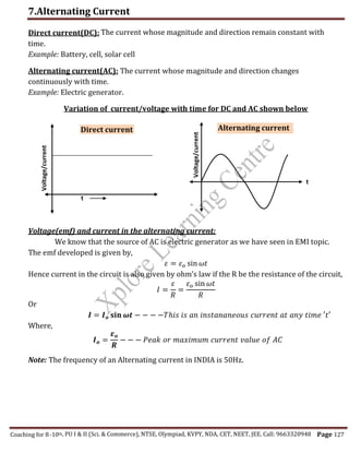
  • 1. 7.Alternating Current Coaching for 8-10th Page 127 Voltage/current Voltage/current Direct current(DC): time. Example: Battery, cell, solar cell Alternating current(AC): The current whose magnitude and direction changes continuously with time. Example: Electric generator. Variation of current/voltage with time for DC and AC shown below Voltage(emf) and current in the alternating current: We know that the source of AC is electric generator as we have seen in EMI topic. The emf developed is given by, 𝜀 = 𝜀𝑜 sin 𝜔𝑡 Hence current in the circuit is also given by ohm’s law if the R be the resistance of the circuit, 𝐼 = 𝜀 𝑅 = 𝜀𝑜 sin 𝜔𝑡 𝑅 Or 𝑰 = 𝑰𝒐 𝐬𝐢𝐧 𝝎𝒕 − − − −𝑇ℎ𝑖𝑠 𝑖𝑠 𝑎𝑛 𝑖𝑛𝑠𝑡𝑎𝑛𝑎𝑛𝑒𝑜𝑢𝑠 𝑐𝑢𝑟𝑟𝑒𝑛𝑡 𝑎𝑡 𝑎𝑛𝑦 𝑡𝑖𝑚𝑒 ′𝑡′ Where, 𝑰𝒐 = 𝜺𝒐 𝑹 − − − 𝑃𝑒𝑎𝑘 𝑜𝑟 𝑚𝑎𝑥𝑖𝑚𝑢𝑚 𝑐𝑢𝑟𝑟𝑒𝑛𝑡 𝑣𝑎𝑙𝑢𝑒 𝑜𝑓 𝐴𝐶 Note: The frequency of an Alternating current in INDIA is 50Hz. t t Direct current Alternating current , PU I & II (Sci. & Commerce), NTSE, Olympiad, KVPY, NDA, CET, NEET, JEE. Call: 9663320948 The current whose magnitude and direction remain constant with
  • 2. 7.Alternating Current Coaching for 8-10th Page 128  Average value of AC over one complete cycle of AC is ZERO.As alternating current is positive in one half cycle and equally negative in the other half cycle so its mean value over complete cycle is zero 𝐼 = 𝑞 𝑇 = 𝑜 We cannot measure AC by using simple moving coil galvanometer, it can be measured by using hot-wire ammeter which is based on heating effect of current. Different values of Alternating Current  Mean OR Average value of A.C.- It is that amount of direct current when passed through a circuit for a half the time period of A.C., it send same amount of charges through the circuit as sent by the A.C. through same circuit in the same time. 𝑰𝒂𝒗 = 𝑰𝒎 = 𝟐 𝝅 𝑰𝒐 = 𝟎. 𝟔𝟑𝟕 𝑰𝒐 Where, 𝐼𝑜 − 𝑝𝑒𝑎𝑘 𝑣𝑎𝑙𝑢𝑒 𝑜𝑓 𝐴. 𝐶. Also for emf we can write, 𝜺𝒂𝒗 = 𝜺𝒎 = 𝟐 𝝅 𝜺𝒐 = 𝟎. 𝟔𝟑𝟕 𝜺𝒐  Root Mean Square(RMS) or Effective value of A.C.- It is that amount of direct current when passed through a resistor for any duration of time period, produces same amount of heat in the resistor as it produced by A.C. in the same resistor in the same time. 𝑰𝒓𝒎𝒔 𝒐𝒓 𝑰𝒆𝒇𝒇 = 𝑰𝒐 √𝟐 = 𝟎. 𝟕𝟎𝟕 𝑰𝒐 Also for emf we can write, 𝜺𝒓𝒎𝒔 𝒐𝒓 𝜺𝒆𝒇𝒇 = 𝜺𝒐 √𝟐 = 𝟎. 𝟕𝟎𝟕 𝜺𝒐 Numerical 1):-A light bulb is rated at 100W for a 220 V supply. Find (a) the resistance of the bulb; (b) the peak voltage of the source; and (c) the rms current through the bul. Numerical 2):-A 100 Ω resistor is connected to a 220 V, 50 Hz ac supply. (a) What is the rms value of current in the circuit? (b) What is the net power consumed over a full cycle? Numerical 3):-a) The peak voltage of an ac supply is 300 V. What is the rms voltage? (b) The rms value of current in an ac circuit is 10 A. What is the peak current? ,
  • 3. 7.Alternating Current Coaching for 8-10th Page 129 PHASOR AND PHASOR DIAGRAM “A rotating vector that represents a varying physical quantity is called as Phasor.” The length of the vector represents the magnitude and and its projection on fixed axis gives the instantaneous value of the quantity To study the alternating current we have to consider a alternating voltage and current as rotating phasors. “Phasor diagram are diagram representing alternating current and voltage of same frequency as vectors or phasors with the phase angle between them and rotating about the origin.” The vertical components of phasors V and I represent the sinusoidally varying quantities v and i. The angle between the V and I phasor is known as phasor angle or simply Phase(∅) AC VOLTAGE APPLIED TO A RESISTOR(R)(3marks) Let a resistor of resistance R is connected to a source of an alternating emf is 𝜺 = 𝜺𝒐 𝒔𝒊𝒏 𝝎𝒕 − − − −(𝟏) Let I be the current in the circuit at any instant of time t , then potential across resistor is given by ohm’s law, 𝐼 = 𝜀 𝑅 = 𝜀𝑜 sin 𝜔𝑡 𝑅 𝑰 = 𝑰𝒐 𝒔𝒊𝒏 𝝎𝒕 − − − −(𝟐) (∵ 𝑰𝒐 = 𝜺𝒐 𝑹 ) Comparing equation (1) and (2) , Current I and the voltage(emf) 𝜺 both are in the same phase. This means that both I and 𝜺 attains the maximum, minimum and zero at the same time. The phasor diagram for purely resistive circuit is shown in below diagram. The phase angle between the current I and 𝜀 is zero. i.e. (∅ = 0𝑜 )(1mark) ,
  • 4. 7.Alternating Current Coaching for 8-10th Page 130 AC VOLTAGE APPLIED TO A INDUCTOR(L)(3marks) Let an Inductor, L is connected to source of alternating current , 𝜀 as shown in fig(a). The varying emf is given by, 𝜺 = 𝜺𝒐 𝒔𝒊𝒏 𝝎𝒕 − − − −(𝟏) The circuit is now purely Inductive a.c. circuit. Let the current I flows through the inductor, then back emf is generated due to EMI which oppose the applied emf. 𝜀 = 𝐿 𝑑𝐼 𝑑𝑡 𝜀𝑜 𝑠𝑖𝑛 𝜔𝑡 = 𝐿 𝑑𝐼 𝑑𝑡 𝑓𝑟𝑜𝑚 𝑒𝑞𝑢𝑎𝑡𝑖𝑜𝑛(1) 𝑑𝐼 = 𝜀𝑜 𝐿 𝑠𝑖𝑛𝜔𝑡.𝑑𝑡 Integrating above equation we get ∫ 𝑑𝐼 = ∫ 𝜀𝑜 𝐿 𝑠𝑖𝑛𝜔𝑡. 𝑑𝑡 𝐼 = − 𝜀𝑜 𝜔𝐿 𝑐𝑜𝑠𝜔𝑡 ⟹ 𝐼 = −𝐼𝑜 cos 𝜔𝑡 where, 𝐼𝑜 = 𝜀𝑜 𝜔𝐿 is the peak value of the current. 𝐼 = −𝐼𝑜 𝑠𝑖𝑛 ( 𝜋 2 − 𝜔𝑡) ∵ [cos 𝜃 = 𝑠𝑖𝑛 ( 𝜋 2 − 𝜃)] 𝜀 = 𝜀 𝑜 sin 𝜔𝑡 Circuit and Phasor digram for only containing resistor(R) 𝑰𝒐𝒔𝒊𝒏𝝎𝒕𝟏 𝜺𝒐𝒔𝒊𝒏𝝎𝒕𝟏 𝜺 𝐼 ,
  • 5. 7.Alternating Current Coaching for 8-10th Page 131 𝑰 = 𝑰𝒐 𝒔𝒊𝒏 (𝝎𝒕 − 𝝅 𝟐 ) − − − −(𝟐) Comparing equation (1) and (2), current I lags behind the emf 𝜺 by 𝝅 𝟐 . It means the phase angle between I and 𝜺 𝑖𝑠 𝝅 𝟐 . i.e. (∅ = 90𝑜 ) as shown in phase diagram (b). INDUCTIVE REACTANCE(𝑿𝑳):It is the effective resistance offered by the inductor to the flow of A.C. It has unit ohm(Ω). We know 𝐼𝑜 = 𝜀𝑜 𝜔𝐿 and 𝐼𝑜 = 𝜀𝑜 𝑅 Comparing above equation we write, 𝑅 = 𝑿𝑳 = 𝜔𝐿 𝑿𝑳 = 𝝎𝑳 = 𝟐𝝅𝒇𝑳 Where, f is the frequency of A.C. supply.  For A.C. ⟹ 𝑿𝑳 ∝ 𝑓.  For D.C. ⟹ f=0 hence 𝑿𝑳 = 0  Thus an inductor allows D.C. through it Easily, but opposes the floe of A.C. through it. 𝑰𝒓𝒎𝒔 = 𝑰𝒐 √𝟐 = 𝜺𝒐 𝝎𝑳√𝟐 = 𝜺𝒓𝒎𝒔 𝝎𝑳 = 𝜺𝒓𝒎𝒔 𝑿𝑳 (a)Circuit (b) Phasor digram (c) variation of I and 𝜀 with 𝜔𝑡 𝜀 = 𝜀 𝑜 sin 𝜔𝑡 𝑰𝒐𝒔𝒊𝒏 (𝝎𝒕𝟏 − 𝝅 𝟐 ) 𝜺𝒐𝒔𝒊𝒏𝝎𝒕𝟏 𝜺 𝑰 (a) (b) (c) 𝜺 Graph of 𝑿𝑳 versus 𝒇 𝑿𝑳 f ,
  • 6. 7.Alternating Current Coaching for 8-10th Page 132 AC VOLTAGE APPLIED TO A CAPACITOR(3marks) Let a capacitor, C is connected to a source of an alternating emf. The capacitor get charged during half cycle and discharges during next half cycle. As result there is a continuous current in the circuit as shown in fig(a) below. We know , 𝜺 = 𝜺𝒐 𝒔𝒊𝒏 𝝎𝒕 − − − −(𝟏) At any instant, Potential across capacitor(V) = Applied emf(𝜺) 𝑉 = 𝑄 𝐶 ⟹ 𝑄 = 𝐶𝑉 𝑄 = 𝐶𝜀 (∵ 𝐶 = 𝜀 ) , 𝑓𝑟𝑜𝑚 𝑒𝑞𝑢𝑎𝑡𝑖𝑜𝑛(1) 𝑄 = 𝐶𝜀𝑜 𝑠𝑖𝑛 𝜔𝑡 By definition of the current at any instant of time ‘t’ is 𝐼 = 𝑑𝑄 𝑑𝑡 𝐼 = 𝑑(𝐶𝜀𝑜𝑠𝑖𝑛 𝜔𝑡) 𝑑𝑡 ⟹ 𝜔𝐶𝜀𝑜𝐶𝑜𝑠𝜔𝑡 𝐼 = 𝜀𝑜𝐶𝑜𝑠𝜔𝑡 (1 𝜔𝐶 ⁄ ) = 𝐼𝑜𝐶𝑜𝑠𝜔𝑡 𝑤ℎ𝑒𝑟𝑒, 𝑰𝒐 = 𝜺𝒐 (𝟏 𝝎𝑪 ⁄ ) = 𝑝𝑒𝑎𝑘 𝑐𝑢𝑟𝑟𝑒𝑛𝑡 𝑰 = 𝑰𝒐𝒔𝒊𝒏 (𝝎𝒕 + 𝝅 𝟐 ) − − − (𝟐) Comparing equation (1) and (2) we can say that current leads the voltage(emf) by angle 𝝅 𝟐 as shown in the phasor diagram below(b).Also phase angle is ∅ = 𝝅 𝟐 = 𝟗𝟎𝒐 (a)Circuit (b) Phasor digram (c) variation of I and 𝜀 with 𝜔𝑡 𝑰𝒐𝒔𝒊𝒏 (𝝎𝒕𝟏 + 𝝅 𝟐 ) 𝜺𝒐𝒔𝒊𝒏𝝎𝒕𝟏 𝜀 = 𝜀 𝑜 sin 𝜔𝑡 𝜺 𝜺 𝑰 ,
  • 7. 7.Alternating Current Coaching for 8-10th Page 133 𝑿𝑪 = 𝟏 𝝎𝑪 ⁄ = 𝟏 𝟐𝝅𝒇𝑪 CAPACITIVE REACTANCE(𝑿𝑪):It is the effective resistance offered by the capacitor to the flow of A.C. It has unit ohm(Ω). We know 𝑰𝒐 = 𝜺𝒐 (𝟏 𝝎𝑪 ⁄ ) and 𝐼𝑜 = 𝜀𝑜 𝑅 Comparing above equation we write, 𝑅 = 𝑿𝑪 = 1 𝜔𝐶 ⁄ Where, f is the frequency of A.C. supply.  For A.C. ⟹ 𝑿𝑪 ∝ 1 𝑓 .  For D.C. ⟹ f = 0 hence 𝑿𝑪 = ∞  Thus an capacitor allows A.C. through it Easily, but block the flow of D.C. through it. 𝑰𝒓𝒎𝒔 = 𝑰𝒐 √𝟐 = 𝜺𝒐 𝟏 𝝎𝑪 ⁄ √𝟐 = 𝜺𝒓𝒎𝒔 𝟏 𝝎𝑪 ⁄ = 𝜺𝒓𝒎𝒔 𝑿𝑪  AC VOLTAGE APPLIED TO A SERIES LCR CIRCUIT(5 marks) Suppose a resistance R, inductor L, and capacitor C are connected in series to a alternating source of emf 𝜀 given by, 𝜺 = 𝜺𝒐 𝒔𝒊𝒏 𝝎𝒕 − − − −(𝟏) Graph of 𝑿𝑪 versus 𝒇 𝑿𝑪 f 𝜀 = 𝜀𝑜 sin 𝜔𝑡 𝜺 ,
  • 8. 7.Alternating Current Coaching for 8-10th Page 134 𝑉𝑐 → R Ø 𝜔𝑡 Ø R Z ε (b)Phasor diagram: For LCR circuit (c)Impedance(Z) triangle From circuit diagram, if I be the current in the circuit then applying ohm’s law to each component, 𝑉𝑅 = 𝐼𝑜𝑅 𝑉𝐿 = 𝐼𝑜𝑋𝐿 𝑉𝐿 = 𝐼𝑜𝑋𝐶 − − − − − (2) 𝑉𝐿 𝑎𝑛𝑑 𝑉𝐶 are in opposite direction, their resultant is ( 𝑉𝐿 − 𝑉𝐶).Hence the resultant of ( 𝑉𝐿 − 𝑉𝐶) and 𝑉𝑅 is equal to the applied emf (𝜺). (𝜺𝒐)𝟐 = (𝑽𝑹)𝟐 + ( 𝑉𝐿 − 𝑉𝐶)𝟐 by Pythagoras thm. From equation (1) and (2) 𝜺𝒐 = √(𝑽𝑹)𝟐 + ( 𝑉𝐿 − 𝑉𝐶)𝟐 𝜺𝒐 = 𝑰𝒐√(𝑹)𝟐 + ( 𝑋𝐿 − 𝑋𝐶)𝟐 𝑰𝒐 = 𝜺𝒐 √(𝑹)𝟐 + ( 𝑋𝐿 − 𝑋𝐶)𝟐 ⟹ 𝜺𝒐 𝒁 Hence 𝒁 = √(𝑹)𝟐 + ( 𝑿𝑳 − 𝑿𝑪)𝟐 Impedance(Z):It is an effective resistance offered by LCR-circuit to the flow of an A.C. current through it. It has unit ohm(Ω). 𝒁 = √(𝑹)𝟐 + ( 𝑿𝑳 − 𝑿𝑪)𝟐 = √(𝑹)𝟐 + ( 𝝎𝑳 − 𝟏 𝝎𝑪 ) 𝟐 𝑉𝐿 → 𝑉𝑅 → 𝐼 𝑉𝐿 − 𝑉𝐶 XL -XC XL -XC ,
  • 9. 7.Alternating Current Coaching for 8-10th Page 135 Special cases 1) When 𝑿𝑳 > 𝑿𝑪 then emf is ahead of current by phase angle Ø which is given by, 𝐭𝐚𝐧 ∅ = 𝑿𝑳 − 𝑿𝑪 𝒁 𝒐𝒓 𝐜𝐨𝐬 ∅ = 𝑹 𝒁 𝑇ℎ𝑒 𝐿𝐶𝑅 𝑐𝑖𝑟𝑐𝑢𝑖𝑡 𝑖𝑠 𝑝𝑢𝑟𝑒𝑙𝑦 𝐼𝑛𝑑𝑢𝑐𝑡𝑖𝑣𝑒 2) When 𝑿𝑳 < 𝑿𝑪 then current is ahead of emf by phase angle Ø which is given by, 𝐭𝐚𝐧 ∅ = 𝑿𝑪 − 𝑿𝑳 𝒁 𝒐𝒓 𝐜𝐨𝐬 ∅ = 𝑹 𝒁 𝑇ℎ𝑒 𝐿𝐶𝑅 𝑐𝑖𝑟𝑐𝑢𝑖𝑡 𝑖𝑠 𝑝𝑢𝑟𝑒𝑙𝑦 𝐶𝑎𝑝𝑎𝑐𝑖𝑡𝑖𝑣𝑒 3) When 𝑿𝑳 = 𝑿𝑪 then current and emf both are phase angle i.e. Ø=0 𝐼𝑜 = 𝜀𝑜 𝑍 𝒐𝒓 𝐼𝑟𝑚𝑠 = 𝜀𝑟𝑚𝑠 𝑍 𝑇ℎ𝑒 𝐿𝐶𝑅 𝑐𝑖𝑟𝑐𝑢𝑖𝑡 𝑖𝑠 𝑝𝑢𝑟𝑒𝑙𝑦 𝐶𝑎𝑝𝑎𝑐𝑖𝑡𝑖𝑣𝑒 Resonance condition of LCR circuit A LCR circuit is said to be in the resonance condition when the current through it has maximum value. Resonant Frequency(fr): The frequency at which the current through LCR circuit is maximum. At resonant frequency the impedance(Z) is minimum. The resonance occurs when 𝑋𝐿 = 𝑋𝐶 2𝜋𝑓𝐿 = 1 2𝜋𝑓𝐶 𝑓2 = 1 4𝜋2𝐿𝐶 ℎ𝑒𝑟𝑒 𝑓 𝑟 = 𝑓 Note: 1)At resonance current and voltage are in same phase i.e Ø=0. The circuit is purely resistive. The current value is given by , 𝐼𝑜 = 𝜀𝑜 𝑅 2)At resonance the power factor is unity 𝐜𝐨𝐬 ∅ = 𝟏 𝒇𝒓 = 𝟏 𝟐𝝅√𝑳𝑪 ,
  • 10. 7.Alternating Current Coaching for 8-10th Page 136 Sharpness of resonance: Quality factor:The sharpness of the resonance depends on the resistance value. If the resistance is small then resonance curve has sharp peak, and flat for the large resistance. The sharpness of resonance is measured by quantity called as Quality Factor(Q). Quality Factor(Q):It is definedas the ratio of the angular resonant frequency to the band width of the circuit. It is given by, 𝑄 = 𝜔𝑟 𝜔2−𝜔1 = 𝜔𝑟 2△𝜔 = 𝜔𝑟𝐿 𝑅 = 𝜔𝑟𝐿 𝑅 = 1 𝜔𝑜𝐶𝑅 = 1 𝑅 √ 𝐿 𝐶 It is dimensionless quantity. POWER IN AC CIRCUIT: THE POWER FACTOR The rate at which the electrical energy is consumed in an electrical circuit is called as power. The instantaneous power is given by, 𝑃 𝑎𝑣 = 𝜀𝑟𝑚𝑠𝐼𝑟𝑚𝑠 cos ∅ but cos ∅ = 𝑅 𝑍 𝑷𝒂𝒗 = 𝜺𝒓𝒎𝒔𝑰𝒓𝒎𝒔. 𝑹 𝒁 ,
  • 11. 7.Alternating Current Coaching for 8-10th Page 137 Power factor(𝒄𝒐𝒔 ∅): The power factor is defined as the ratio os the true power to the apparent power of an A.C. circuit. It is dimensionless quantity. It is given by cos ∅ = 𝑅 𝑍 = 𝑅 √(𝑹)𝟐 + ( 𝝎𝑳 − 𝟏 𝝎𝑪 ) 𝟐 Special cases:  Purely resistive circuit: Here ∅ = 0 and cos ∅ = 1 𝑃 𝑎𝑣 = 𝜀𝑟𝑚𝑠𝐼𝑟𝑚𝑠 × 1 = 𝜀𝑟𝑚𝑠 × 𝐼𝑟𝑚𝑠 𝑷𝒂𝒗 = (𝜺𝒓𝒎𝒔)𝟐 𝑹  Purely inductive circuit: Here ∅ = 𝜋 2 and cos ∅ = 0 𝑷𝒂𝒗 = 𝟎  Purely capacitive circuit: Here ∅ = 𝜋 2 and cos ∅ = 0 𝑷𝒂𝒗 = 𝟎  In series LCR circuit: 𝑃 𝑎𝑣 = 𝜀𝑟𝑚𝑠𝐼𝑟𝑚𝑠 cos ∅ Where ∅ = 𝐭𝐚𝐧−𝟏 ( 𝑿𝑪−𝑿𝑳 𝒁 )  Power dissipated at resonance condition in LCR-circuit: Here ∅ = 0 and cos ∅ = 1 also 𝑿𝑪 = 𝑿𝑳 𝑃 𝑎𝑣 = 𝜀𝑟𝑚𝑠𝐼𝑟𝑚𝑠  Wattles Current: The current in the A.C. circuit is said to wattles if the power consumed in the circuit is ZERO.i.e. 𝑃 𝑎𝑣 = 0 (1marks) Numerical:A sinusoidal voltage of peak value 283 V and frequency 50 Hz is applied to a series LCR circuit in which R = 3 Ω, L = 25.48 mh, and C = 796 µf. Find (a) the impedance of the circuit; (b) the phase difference between the voltage across the source and the current; (c) the power dissipated in the circuit; and (d) the power factor. ,
  • 12. 7.Alternating Current Coaching for 8-10th Page 138 LC- OSCILLATIONS: When a charged capacitor is allowed to discharge through a inductor, an electrical oscillation of constant amplitude and frequency are produced. These oscillations are called as LC- oscillations. Frequency of oscillation is given by, 𝒇 = 𝟏 𝟐𝝅√𝑳𝑪 ANALOGIES BETWEEN MECHANICAL AND ELECTRICAL QUANTITIES Mechanical system Electrical system Mass, m Inductance, L Displacement , x Charge, q Velocity, 𝑣 = 𝑑𝑥 𝑑𝑡 Current, 𝑖 = 𝑑𝑞 𝑑𝑡 Force constant, k Reciprocal capacitance, 1 𝐶 Mechanical energy 𝐸 = 1 2 𝑘𝑥2 + 1 2 𝑚𝑣2 Electromagnetic Energy 𝐸 = 𝑞2 2𝐶 + 1 2 𝐿𝐼2 Frequency, 𝒇 = 𝟏 𝟐𝝅 √ 𝒌 𝒎 Frequency, 𝒇 = 𝟏 𝟐𝝅√𝑳𝑪 LC oscillator are damped due to following reasons: Means amplitude of oscillation goes on decreases due to, 1) Every inductor has some resistance 2) total energy of the system would not remain constant ,
  • 13. 7.Alternating Current Coaching for 8-10th Page 139 TRANSFORMER The electrical device which change (or transform) an alternating voltage from one to another of greater or smaller value. Transformer works on the principal of mutual inductance. Construction: A transformer consists of two sets of coils, insulated from each other. They are wound on a soft-iron core, either one on top of the other or on separate limbs of the core. One of the coils called the primary coil has Np turns. The other coil is called the secondary coil it has Ns turns. The primary coil is the input coil and the secondary coil is the output coil of the transformer. Working: It works on the principle of mutual induction of two coils or Faraday Law’s Of Electromagnetic induction. When current in the primary coil is changed the flux linked to the secondary coil also changes. Hence an EMF is induced in the secondary coil due to Faraday law’s of electromagnetic induction. Then the induced emf in the second coil is given by, 𝜀𝑠 = −𝑁𝑠 𝑑∅ 𝑑𝑡 − − − (1) Also the induced back emf in the primary coil is given by, 𝜀𝑃 = −𝑁𝑃 𝑑∅ 𝑑𝑡 − − − (2) Dividing equation (1) and(2) we get, Two arrangements for winding of primary and secondary coil in a transformer: (a) two coils on top of each other, (b) two coils on separate limbs of the core. ,
  • 14. 7.Alternating Current Coaching for 8-10th Page 140 𝜀𝑠 𝜀𝑃 = 𝑁𝑠 𝑁𝑃 (∵ 𝜀𝑠 = 𝑉 𝑠 𝑎𝑛𝑑 𝜀𝑃 = 𝑉𝑃) 𝑉 𝑠 𝑉𝑃 = 𝑁𝑠 𝑁𝑃 − − − (3) If there is no loss of energy while transform, then there is no loss of energy , then Input power = Output power 𝑃𝑖𝑛𝑝𝑢𝑡 = 𝑃𝑜𝑢𝑡𝑝𝑢𝑡 𝐼𝑃𝑉𝑃 = 𝐼𝑆𝑉𝑆 𝑉 𝑠 𝑉𝑃 = 𝐼𝑃 𝐼𝑆 − − − −(4) From (3) and (4) , 𝑰𝑷 𝑰𝑺 = 𝑽𝒔 𝑽𝑷 = 𝑵𝒔 𝑵𝑷 In transformers, small energy losses do occur due to the following reasons(3marks)  Copper loss  Eddy current loss  Hysteresis loss  Flux leakage  Humming loss Application of Transformer  Small transformer used in radio, mobile charger, loudspeaker  In voltage regulator, refrigerator, computer etc.  Electric welding  Transmission of electrical energy. ,
  • 15. 7.Alternating Current Coaching for 8-10th Page 141 TYPE OF TRANSFORMERS Step-up transformer  The transformer which increases the input voltage.  The number of primary turns in the primary coil is less than that of secondary coil.  Np < NS  Step-down transformer  The transformer which decrease the input voltage.  The number of primary turns in the primary coil is greater than that of secondary coil.  Np > NS  Advantages of A.C. over D.C  The generation of A.C. is more economical than D.C.  A.C can be easily stepped up or stepped down using transformer, but cannot D.C  A.C. can be transmitted through a long distance without loss of energy.  A.C easily converted into D.C using rectifiers.  Machine works on A.C are simple Disadvantages of A.C. over D.C  Peak value of A.C is high. It is dangerous to work with it.  In phenomenon like electroplating, electrolysis A.C cannot be used.  A.C. transmitted more from surface of conductor than from inside, hence several insulation thin wires are required for transmission. ,
  • 16. 7.Alternating Current Coaching for 8-10th Page 142 ONE MARK QUESTIONS 1. What is the phase angle between current and voltage across a resistor when AC is applied to a pure resistor? 2. Define root mean square value of current or voltage. 3. How the RMS value and peak value of current /voltage are related? 4. If the peak value of current is 1.41A, then what is the value of root mean square current? 5. What is a phasor diagram in AC circuits? 6. Define power factor in an AC circuit. 7. What is wattles current? 8. The peak voltage of an AC supply is 300 V. What is the RMS voltage? 9. Write the expression for inductive reactance in terms of frequency of AC applied. 10.Write the expression for capacitive reactance in terms of frequency of AC applied. 11.What is the power factor of an AC circuit containing a pure inductor? 12.What is the power factor of an AC circuit containing only capacitor? 13.What is the power factor of an AC circuit containing only pure resistor? 14.Give the expression for power factor in an AC circuit containing an inductor, a capacitor and a resistor in series. 15.What is electrical resonance in RLC series circuit? 16.Define resonant frequency of an RLC series circuit. 17.What is an ideal transformer? 18.On what principle a transformer works? 19.The number of turns in the primary of a transformer is greater than the number of turns in the secondary. Does the voltage steps-up or steps down in it? 20.What is a step-up transformer? 21.What is a step-down transformer? 22.What is the reactance of an inductor in a dc circuit carrying a steady current? 23.Which physical quantity in electrical system is analogue to ‘mass’ of the mechanical system? TWO MARK QUESTIONS 1. Mention any two advantages of AC over DC. 2. What is quality factor in an LCR series circuit? Give the expression for it. 3. Write the expression for resonant frequency of RLC series circuit and explain the terms. 4. Alternating current is represented by the equation I = I0 Sin(314)t . Find the value of frequency of AC. 5. Write any two differences between inductive reactance and capacitive reactance. 6. Give any two differences between step- up transformer and step- down transformer. 7. What is the phase difference between voltage and current when an AC is connected to a capacitor? Represent it using phasor diagram. ,
  • 17. 7.Alternating Current Coaching for 8-10th Page 143 8. What is the phase difference between voltage and current when an AC is connected to an inductor? Represent it using phasor diagram. 9. What is the phase difference between voltage and current when an AC is connected to a resistor? Represent it using phasor diagram. 10. Draw a graph of variation of voltage and current versus ωt in case of an inductor connected to an AC source. 11. Draw a graph of variation of voltage and current versus ωt in case of a resistor connected to an AC source. 12. Draw a graph of variation of voltage and current versus ωt in case of an inductor connected to an AC source. 13. What is capacitive reactance? Give the expression for it in terms of frequency of applied AC. 14. What is inductive reactance? Give the expression for it in terms of frequency of applied AC. 15. A power transmission line feeds input power at 2300 V to a step down transformer with its primary windings having 4000 turns. What should be the number of turns in the secondary in order to get output power at 230 V? 16. A charged 30 μF capacitor is connected to a 27 mH inductor. What is the angular frequency of free oscillations of the circuit? THREE MARK QUESTIONS 1. Derive the expression for current in case of AC applied to a pure resistor. 2. Obtain the expression for current in case of AC applied to an inductor. 3. Derive the expression for current through a capacitor when AC is applied. 4. What is resonance in LCR series circuit? Obtain the expression for resonant frequency of it. 5. Mention any three energy losses in a transformer. 6. Explain how power is dissipated by writing the expression for power factor in case of (i) pure inductive or capacitive (ii) series LCR (iii) series LCR at resonance circuits. ,
  • 18. 7.Alternating Current th Page 144 FIVE MARK QUESTIONS 1. Show that the relation between AC current and AC voltage in case of AC applied to a resistor is similar to that in the DC applied to it. (U) 2. Derive the expression for impedance and hence the current of an RLC series circuit connectedto an AC using phasor diagram. 3. Give the construction and working of a transformer. NUMERICAL PROBLEMS 1. A 50Ω resistor, 0.5H inductor and 200µF capacitor are connected in series with 220V and 50Hz source. Find the impedance of the circuit and hence the current. [149.7Ω, 1.47A] 2. A current of 4A flows in a coil when connected to a 12V d.c.source. if the same coil is connected to 12V, 50Hz a.c. source, a current of 2.4A flows in the circuit. Calculate the self- inductance of the coil. [80mH] 3. A resistance of 10Ω is connected in series with an inductor of inductance 0.5H. These two are connected to 200V, 50Hz a.c. source. Calculate the capacitance that should be put in series with the combination to obtain the maximum current? Also find the current through the circuit. [20.24µF, 20A] 4. A source of 220V, 40Hz is connected to a series combination of 6Ω resistor, 0.01H inductor. Calculate the phase angle and the power factor of the circuit.[22042’, 0.92] 5. In a step-down transformer having primary to secondary turns ratio 20:1, the input voltage applied is 250V and output current is 8A. Assuming 100% efficiency calculate (i) voltage across the secondary coil, (ii) current in primary coil (iii) output power. [12.5V, 0.4A, 100W] ,