Forming1
•Télécharger en tant que PPT, PDF•
4 j'aime•1,182 vues

The document discusses various metal forming processes, specifically focusing on forging and rolling. It defines forming, cold working, warm working and hot working based on the temperature of deformation relative to the material's melting point. The key forming processes covered are forging (smith forging, drop forging, press forging, machine forging), rolling (functions, types of mills, drafting), and extrusion (forward and backward extrusion, uses). Diagrams illustrate examples and defects are also outlined for each process.

Recommandé
Contenu connexe
Tendances
Tendances (20)
En vedette
En vedette (12)
Similaire à Forming1
Similaire à Forming1 (20)
Dernier
Dernier (20)
Forming1
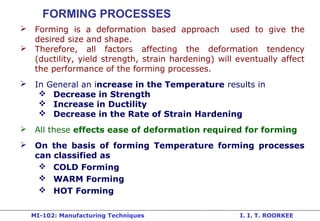
- 1. MI-102: Manufacturing Techniques I. I. T. ROORKEE FORMING PROCESSES Forming is a deformation based approach used to give the desired size and shape. Therefore, all factors affecting the deformation tendency (ductility, yield strength, strain hardening) will eventually affect the performance of the forming processes. In General an increase in the Temperature results in Decrease in Strength Increase in Ductility Decrease in the Rate of Strain Hardening All these effects ease of deformation required for forming On the basis of forming Temperature forming processes can classified as COLD Forming WARM Forming HOT Forming
- 2. MI-102: Manufacturing Techniques I. I. T. ROORKEE COLD FORMING HOT FORMING Below their Recrystallization Temperature Above their Recrystallization Temperature Temperature of Deformation < 0. 3 Melting Temperature on the Absolute Scale Temperature of Deformation > 0.6 Melting Temperature on the Absolute Scale Recrystallization Temperature Varies Greatly with the Material Tin is Near Hot-Working at Room Temperature while Steel Require Temp. near 1100o C WARM FORMING: Deformation Between 0.3 to 0.6 Times the Melting Point on the Absolute Scale
- 3. MI-102: Manufacturing Techniques I. I. T. ROORKEE Hot Working Cold Working Processes Forging Rolling Extrusion Hot Drawing Piercing Squeezing: Cold Rolling, Cold Forging , Cold Extrusion, Coining, Peening, Burnishing, and Thread Rolling. Bending: Angle Bending, Roll Bending, Roll-forming, and Straightening. Shearing: Slitting, Blanking, Piercing, Notching, Nibbling, Drawing: Spinning, Embossing, Stretch Forming, and Ironing Sheet-metal Forming Operations
- 4. MI-102: Manufacturing Techniques I. I. T. ROORKEE FORGING Involves application of force on metal to cause plastic deformation so as to get the required final shape. Forging is Generally a Hot Working but also be Cold Forging. Forging can be done in two ways Drawing Out: Elongates the object with a Reduction in the Cross-Sectional Area using Force Applied in a Direction Perpendicular to the longitudinal Axis. Upsetting: increases the Cross- Sectional Area of the Stock at the Expense of its Length using Force Applied in a Direction Parallel to the Length Axis. Drawing Out Upsetting
- 5. MI-102: Manufacturing Techniques I. I. T. ROORKEE FORGING TYPES Smith Forging: Traditional Forging performed using Open Dies with help of Manual or Powered Hammers. Drop Forging: uses Closed Impression Dies by Means of Drop Hammers in a Series of Blows. Press Forging: is Similar to Drop Forging with the Difference that the Force is a Continuous Squeezing Type. Machine Forging: the Material is only Upset to Get the Desired Shape using a set of dies.
- 6. MI-102: Manufacturing Techniques I. I. T. ROORKEE
- 7. MI-102: Manufacturing Techniques I. I. T. ROORKEE SMITH FORGING Involves Heating the Stock in the Blacksmith's Hearth and then Beating it Over the Anvil. The stock is Manipulated in Between the Blows. Used for low volume production of variety of designs.
- 8. MI-102: Manufacturing Techniques I. I. T. ROORKEE The Drop Forging Die Consists of Two Halves. The Lower Half is Fixed to the Anvil of the Machine, While the Upper Half of the Die is Fixed to the Ram. The Heated Material Stock is Kept in the Lower Die while the Ram Delivers Four to Five Blows on the Material, in Quick Succession so that the Material Spreads and Completely Fills the Die Cavity. When the Two Die Halves Close, the Complete Cavity is Formed. Since the Machined impressions in the Die Cavity help to get more Complex Shapes in Drop Forging as Compared to Smith Forging
- 9. MI-102: Manufacturing Techniques I. I. T. ROORKEE Drop forging
- 10. MI-102: Manufacturing Techniques I. I. T. ROORKEE Typical Products Produced by Drop Forging are Crank, Crank Shaft, Connecting Rod, Wrench, Crane Hook, etc. Final Shape Desired in Drop Forging Cannot be Obtained Directly from the Stock in a Single Pass. Depending on the Shape of the Component, and the Desired Grain Flow Direction, the Material should be Manipulated in a Number of Passes.
- 11. MI-102: Manufacturing Techniques I. I. T. ROORKEE FULLERING IMPRESSION: Reducing Stock to the Desired Size. EDGING IMPRESSION (Preforming): Ensures Defect-Free Flow of Material, Complete Die Fill and Minimum Flash Loss. BENDING IMPRESSION: for the Parts having a Bent Shape. BLOCKING is a Step before Finishing. The Material Flows to Deep Pockets, Sharp Corners, etc. before the Finishing Impression without Flash. FINISHING: is the Final Impression for Actual Shape .at this stage a Little Extra Material is Added to the Stock Forms the Flash and Surrounds the Forging in the Parting Plane. TRIMMING is removal of the Extra Flash Present Around the Forging to make the Forging in Usable .
- 12. MI-102: Manufacturing Techniques I. I. T. ROORKEE In Press Forging, involves Single Continuous Squeezing Action results in Uniform Deformation Throughout the Depth. The Impressions Produced in the Press Forging are Cleaner as Compared to the Jarred Impressions Produced in the Drop Forged Components. Press forging suits for smaller size components than drop forging as former needs higher Press Capacity for Deforming in Closed Impression Dies. No such Limitation for Press Forging in Open Dies. Presses Capacities May Range from 5 MN to 50 MN for Normal Applications and as High as 600 MN for Special Heavy Duty Applications. PRESS FORGING
- 13. MI-102: Manufacturing Techniques I. I. T. ROORKEE Initially Developed for Making the Bolt Heads in a Continuous Fashion. Due to Beneficial Grain Flow Obtained in Upsetting, it is Used for Making Gear Blanks, Shafts, Axles and Similar Parts. Some Typical Parts Produced by Upset Forgings are Shown in the Figure. The Die Set Consists of a Die and a Corresponding Punch or a Heading Tool. MACHINE FORGING
- 14. MI-102: Manufacturing Techniques I. I. T. ROORKEE The Upset Forging Cycle Movable Die comes closer to Stationary Die to Grip the Stock. The Two Dies in Closed Position Form the Necessary Die Cavity. The Punch Upsets stock to Fill the Die Cavity. After Upsetting, Punch Moves Back to its Position. Movable Grippes Release the Stock. Similar to Drop Forging, the Upsetting Operation is Carried Out in a Number of Stages or Passes. The Material Stock is Moved from One Stage to the Other in a Proper Sequence Till the Final Forging is Ready. MACHINE FORGING
- 15. MI-102: Manufacturing Techniques I. I. T. ROORKEE Some Typical Upset or Machine Forged Components
- 16. MI-102: Manufacturing Techniques I. I. T. ROORKEE FORGING DEFECTS Unfilled Sections: of Die Cavity by the Flowing Material due to: Improper Design of Forging Die or Faulty Forging Techniques. Cold Shut: A Small Crack at the Corners of the Forging due to Improper Design of the Die e.g. Corner and Fillet Radii are Small which in turn results in small cracks due to poor flow of materials at the Corner. Scale Pits: Irregular Depressions on the Surface of the Forging primarily due to improper Cleaning of the Stock Used for Forging. The Oxide and Scale Present on the Stock Surface Gets Embedded into the Finished Forging Surface. When the Forging is Cleaned by Pickling, these are Seen as Depressions on the Forging Surface.
- 17. MI-102: Manufacturing Techniques I. I. T. ROORKEE Die Shift: CAUSES: Die Shift is Caused by the Misalignment of the Two Die Halves Making the Two Halves of the Forging to be of Improper Shape. Flakes: These are Basically Internal Ruptures due to poor ductility of surface layer during deformation caused by Rapid Cooling
- 18. MI-102: Manufacturing Techniques I. I. T. ROORKEE ROLLING Rolling is a Process where the Material is Compressed Between Two Rotating Rolls for Reducing its Cross- Sectional Area. Rolling is Normally a Hot Working Process unless specified as Cold Rolling. At Entry, the Surface Speed of Rolls is Higher than that of the Incoming Material, whereas the Material Velocity at the Exit is Higher than that of the Surface Speed of the Rolls due to difference cross sectional area.
- 19. MI-102: Manufacturing Techniques I. I. T. ROORKEE Scheme of Rolling Process
- 20. MI-102: Manufacturing Techniques I. I. T. ROORKEE Rougher Rolls Achieve Greater Reduction than Smoother Rolls. But, the Rough Roll Surface may Get Embedded into the Rolled Metal thus Producing Rough Surface. The Reduction that could be Achieved with a Given Set of Rolls is Designated as the Angle of Bite. This Depends on the Type of Rolling and the Conditions of the Rolls as shown in Table.
- 21. MI-102: Manufacturing Techniques I. I. T. ROORKEE ROLLING STAND 2-High Reversing Rolling Stand: Direction of Roll Rotation can be Reversed these reduce Handling of the Hot Material in Between the Rolling Passes.
- 22. MI-102: Manufacturing Techniques I. I. T. ROORKEE 3-High Rolling Stand: Arrangement is Used for Rolling of Two Continuous Passes in a Rolling Sequence without Reversing the Drives. A Table-Tilting Arrangement is Required to Bring the Material to the Level with the Rolls.
- 23. MI-102: Manufacturing Techniques I. I. T. ROORKEE 4-High Rolling Stand: Backup Rolls for Providing the Necessary Rigidity to the Small Rolls.
- 24. MI-102: Manufacturing Techniques I. I. T. ROORKEE Since Required Final Shape Cannot be Obtained in a Single Pass The Rolling Mills are Generally need More than One Pass to other stands or by Reversing the Roll Direction or The Steel Ingot: 600 x 600 mm. These Ingots are Further Processed in Rolling Mills to Produce the Intermediate Shapes such as Blooms, Slabs and Billets. Blooms: 150 x 150 mm to 400 x 400 mm (square). Slabs: 500 to 1800 mm and Thickness from 50 to 300 mm (rectangle). Billets: from 40 x 40 mm to 150 x 150 mm (rectangle).
- 25. MI-102: Manufacturing Techniques I. I. T. ROORKEE Roll Pass Sequence can be Broadly Categorized into THREE Types: 1. Break Down Pass: Used for Reducing the Cross-Sectional Area Nearer to what is Desired. 2. Roughing Pass: The Cross-Section Gets Reduced, but Shape of the Rolled Material also Comes Nearer to the Final Shape. 3. Finishing Pass: Gives the Required Shape of the Rolled Section. ROLL PASSES
- 26. MI-102: Manufacturing Techniques I. I. T. ROORKEE DRAUGHT If the Cross Section of the Product Before and After Rolling Process is A x B and a x b Respectively, DRAFT is Defined as (A + B)- (a + b) Roll Pass Schedule can be obtained from Draught. If Mean Draught for Each Pass is Known, then Number of Passes can be Estimated. Draught Provided in Each Pass also Depends on the Work Material, Angle of Bite, Roll Strength, Power of the Rolling Mill, and Condition of the Rolls.
- 27. MI-102: Manufacturing Techniques I. I. T. ROORKEE Draughts of All the Passes in the Rolling Sequence are NOT the Same. The Main Criteria for Choosing the Draught is the Angle of Bite. Lower draught is used in subsequent passes. Reason for Reducing Draught in the Later Passes: in Hot Rolling the Reduction in Stock Thickness which Causes it to Lose Heat Quickly and thus Increases the Rolling Load. in Cold Rolling, the Strain Hardening of the Stock Material Necessitates a Reduction in Draught in the Succeeding Passes. Selection of draught
- 28. MI-102: Manufacturing Techniques I. I. T. ROORKEE EXTRUSION In Extrusion Process, the Material is Confined in a Closed Cavity and then Forced to Flow From Only One Opening so that the Material Takes the Shape of the Opening.
- 29. MI-102: Manufacturing Techniques I. I. T. ROORKEE Used to Make Components having a Constant Cross-Section over any Length. More Complex Parts can be Obtained by Extrusion than that of Rolling, as Die become Simple and Easier to Make. Extrusion is a Single Pass Process. The Amount of Reduction Possible in Extrusion is Large. Generally Brittle Materials can Also be Very Easily Extruded. Typical Extrusion Shapes
- 30. MI-102: Manufacturing Techniques I. I. T. ROORKEE Extrusion Ratio is Defined as the Ratio of Cross-Sectional Area of the Billet to that of the Extruded Section. Typical Values of the Extrusion Ratio are 20 to 50. The Extrusion Pressure for a Given Material Depends on the Extrusion Temperature, Reduction in Area, and Extrusion Speed
- 31. MI-102: Manufacturing Techniques I. I. T. ROORKEE CLASSIFICATION OF EXTRUSION PROCESS
- 32. MI-102: Manufacturing Techniques I. I. T. ROORKEE FORWARD HOT EXTRUSION The Direction of Flow of Material is the Same as that of the Ram. Friction is Important Because of the Relative Motion Between the Heated Material Billet and the Cylinder Walls. Lubricants are to be used To Reduce this Friction. Forward Extrusion For Low Temperatures:, Oil Mixture and Graphite For High Temperature, Molten Glass for Extruding Steels.
- 33. MI-102: Manufacturing Techniques I. I. T. ROORKEE BACKWARD or INDIRECT HOT EXTRUSION The Ram Compresses the Material Against the Container, Forcing the Material to Flow Backwards through the Die in the Hollow Plunger or Ram. Since Billet in the Container Remains Stationary No Friction. Backward Extrusion Extrusion Pressure is Not Affected by the Length of the Billet as friction in absent Problem is imposed by Handling Extruding Material Coming Out through the Moving Ram.
- 34. MI-102: Manufacturing Techniques I. I. T. ROORKEE FORWARD COLD EXTRUSION Forward Cold Extrusion is Similar to the Forward Hot Extrusion Process Except with low Extrusion Ratios and high Extrusion Pressures. Used for Simple Shapes with Better Surface Finish and Mechanical Properties. IMPACT EXTRUSION It is modification of Backward Cold Extrusion Carried Out by the Impact Force of the Punch. Material is Extruded through the Gap Between the Punch and Die Opposite to the Punch Movement. Suitable for Softer Materials such as Aluminum and its Alloys. Used for Making the Collapsible Tubes for Housing Pastes, Liquids and similar Articles.
- 35. MI-102: Manufacturing Techniques I. I. T. ROORKEE Impact Extrusion
- 36. MI-102: Manufacturing Techniques I. I. T. ROORKEE COLD EXTRUSION FORGING: The Cold Extrusion Forging is Similar to Impact Extrusion, the Main Difference being the Side Walls much Thicker and with More Height. The Component is Ejected by Means of the Ejector Pin Provided in the Die
- 37. MI-102: Manufacturing Techniques I. I. T. ROORKEE HYDROSTATIC EXTRUSION: The Material Billet is Compressed from all Sides by a Liquid Rather than the Ram. The Material is Uniformly Compressed from All Sides throughout the Deformation Zone. Consequently Highly Brittle Materials such as Grey Cast Iron can also be Extruded. Commercial Applications of the Hydrostatic Extrusion are Limited to Extrusion of Reactor Fuel Rods, Cladding of Metals, and Making Wires of Less Ductile Materials.
- 38. MI-102: Manufacturing Techniques I. I. T. ROORKEE Hydrostatic Extrusion
- 39. MI-102: Manufacturing Techniques I. I. T. ROORKEE WIRE DRAWING Wire Drawing is a cold working process to Obtain Wires from Rods of Bigger Diameter through a Die. The End of the Rod is Made into a Point Shape and Inserted through the Die Opening then Pull the Wire through the Die with help of griper Material to be Wire Drawn should be Sufficiently Ductile. DRAWING
- 40. MI-102: Manufacturing Techniques I. I. T. ROORKEE Wire Drawing Set Up Various Die Materials Used are Chilled Cast Iron, Tool Steels, Alloy Steels, Tungsten Carbide and Diamond.
- 41. MI-102: Manufacturing Techniques I. I. T. ROORKEE In Tube Drawing, a Mandrel of the Requisite Diameter is Used to Form the Internal Hole. The Tubes are also First Pointed and then Entered through the Die where the Point is Gripped in Similar way as the Wire Drawing and Pulled Through. TUBE DRAWING
- 42. MI-102: Manufacturing Techniques I. I. T. ROORKEE SHEET METAL OPERATIONS Metal Sheet: Plates of thickness < 5 mm Sheet metal operations use different types of stresses for processing Shear stress is primarily used in sheet metal processing Stress Induced Operations Shearing Shearing, Blanking, Piercing, Trimming, Shaving, Notching, Nibbling Tension Stretch-Forming Compression Ironing, Coining Tension and Compression Drawing, Spinning, Bending, Embossing, Forming
- 43. MI-102: Manufacturing Techniques I. I. T. ROORKEE SHEARING The Sheet IS deformed between two shearing Blades (developing tensile and compressive stress). Then cracks nucleate and grow when material near cutting edges is elongated beyond fracture limit which later join for separation.
- 44. MI-102: Manufacturing Techniques I. I. T. ROORKEE BLANKING: Process of obtaining a small piece of strip by cutting (shearing from the Stock with help of a Punch. The removed strip is Called Blank used for further processing to get useable product. Blanking/Punching Die PUNCHING: Similar to blanking except that objective is to make Holes in Sheet and removed strip is considered as scrap
- 45. MI-102: Manufacturing Techniques I. I. T. ROORKEE WITHOUT PROPER GRIPPING OF SHEET ROUGH EDGE
- 46. MI-102: Manufacturing Techniques I. I. T. ROORKEE WITH PROPER GRIPPING OF SHEET CLEAN AND SMOOTH EDGE
- 47. MI-102: Manufacturing Techniques I. I. T. ROORKEE TRIMMING: Removing Small Amount of Extra Material Spread Out Near the Parting Plane such as Drop Forging and Die Casting. SHAVING Removal of the Burrs Generated during the Shearing Process in the Blanking or Punching Operation so as to achieve the Close Tolerance Work. NIBBLING: Removing the Material in Small Increments to Cut a Specific Contour on a Sheet using repeating Punching. Nibbling is Used When the Contour is Long and a Separate Punch is Impractical and Uneconomical. NOTCHING: Cutting a Specified Small Portion of Material Towards the Edge of the Material Stock.
- 48. MI-102: Manufacturing Techniques I. I. T. ROORKEE
- 49. MI-102: Manufacturing Techniques I. I. T. ROORKEE STRETCH-FORMING The Sheet is Clamped at ends and Stretched over the Die so as to achieve plastic State and permanent deformation. SHEET METAL OPERATIONS INVOLVING TENSION
- 50. MI-102: Manufacturing Techniques I. I. T. ROORKEE Stretch forming
- 51. MI-102: Manufacturing Techniques I. I. T. ROORKEE IRONING It involves thinning and lengthening of the wall of material by generating compressive stress between the Die and Punch having using the Clearance (spacing) finer than the Drawing Operation. Up to 50% thinning can be obtained in a Single Ironing Operation Ironing Operation SHEET METAL OPERATIONS INVOLVING COMPRESSION
- 52. MI-102: Manufacturing Techniques I. I. T. ROORKEE COINING It is just like a Cold Forging Operation except that the Flow of the Material Occurs Only at the Top Layers and NOT in the Entire Volume. The Punch and Die have Engraved Details Required on Both Sides of the Final Object and uses high pressure (1600 MPa) to get Fine Details on the Surface. For Making Coins, Medals & Impressions on Decorative Items
- 53. MI-102: Manufacturing Techniques I. I. T. ROORKEE DRAWING/DEEP DRAWING Drawing is the Process of Making Cups (high < half diameter), and similar product, from Metal Blanks. When the Cup Height is More than Half the Diameter, the Drawing Process is known as Deep Drawing. SHEET METAL OPERATIONS INVOLVING TENSION and COMPRESSION
- 54. MI-102: Manufacturing Techniques I. I. T. ROORKEE Blank Holding in Deep Drawing
- 55. MI-102: Manufacturing Techniques I. I. T. ROORKEE SPINNING Used for Making Axi-Symmetrical Cup Shaped Articles. Force (moving) is Applied on the Rotating Blank is Held Against the Form Block so as get Shape of the Form Block (of wood).
- 56. MI-102: Manufacturing Techniques I. I. T. ROORKEE BENDING Operation of Deforming a Flat Sheet Around a Straight Axis at the Neutral Plane. When material is subjected to plastic deformation, the Neutral Axis Moves Downward due to differential strain on both sides of neutral axis as the Materials Oppose Compression in much Better way than Tension. Nomenclature of Bending and Type of Bending Methods are Shown in Following Figures.
- 57. MI-102: Manufacturing Techniques I. I. T. ROORKEE Nomenclature of Bending
- 58. MI-102: Manufacturing Techniques I. I. T. ROORKEE Type of Bending Methods
- 59. MI-102: Manufacturing Techniques I. I. T. ROORKEE EMBOSSING An Operation for Making Raised Figures/letter on Sheets with its Corresponding Relief on the Other Side. The Process Involves Drawing and Bending of the Material. Generally Used for increasing the Rigidity by localized deformation and for Decorative Sheet Work.