METHODOLOGY FOR SLUG CATCHER SIZING
•
8 likes•4,230 views

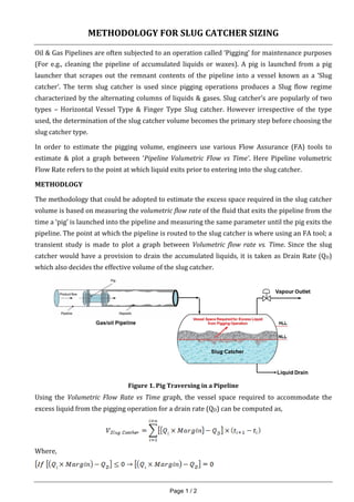
Oil & Gas Pipelines are often subjected to an operation called ‘Pigging’ for maintenance purposes (For e.g., cleaning the pipeline of accumulated liquids or waxes). A pig is launched from a pig launcher that scrapes out the remnant contents of the pipeline into a vessel known as a ‘Slug catcher’. The term slug catcher is used since pigging operations produces a Slug flow regime characterized by the alternating columns of liquids & gases. Slug catcher’s are popularly of two types – Horizontal Vessel Type & Finger Type Slug catcher. However irrespective of the type used, the determination of the slug catcher volume becomes the primary step before choosing the slug catcher type.
![Page 2 / 3
The purpose of introducing a factor of ‘margin’ in estimating the Slug catcher volume is due to
uncertainties that Flow Assurance Tools can produce as well as the users’ convergence criteria in
arriving at a well converged volumetric flow rate vs time graph. This can be anywhere from 2%
to 30% and is incumbent upon the Flow Assurance Engineer to thoroughly understanding the
principles of FA & the respective FA solver prior to carrying out slug catcher volume calculations.
Following on the equations provided, a tabulation of the volumetric flow rate vs time can be
made in MS-Excel as,
Time [sec]
Volumetric Flow
Rate [m3/s]
Pigging Volume [m3]
ti Qi
ti+1 Qi+1
ti+2 Qi+2
ti+3 Qi+3
.. .. ….
Cumulative Slug/Pigging Volume
Below is an example graph of pigging volume estimated using the above method for a given drain
rate (QD). The cumulative slug/pig volume computed is the area represented under the total
liquid volume flow into the slug catcher curve (‘blue’ line). The ‘red’ line represents the total
liquid volumetric flow that enters the slug catcher while the vessel is constantly drained.
Figure 2. Example of Slug Catcher Volume Required (Illustration Purposes Only)](data:image/gif;base64,R0lGODlhAQABAIAAAAAAAP///yH5BAEAAAAALAAAAAABAAEAAAIBRAA7)
Recommended
Recommended
More Related Content
What's hot
What's hot (20)
Similar to METHODOLOGY FOR SLUG CATCHER SIZING
Similar to METHODOLOGY FOR SLUG CATCHER SIZING (20)
More from Vijay Sarathy
More from Vijay Sarathy (20)
Recently uploaded
Recently uploaded (20)
METHODOLOGY FOR SLUG CATCHER SIZING
- 1. Page 1 / 2 METHODOLOGY FOR SLUG CATCHER SIZING Oil & Gas Pipelines are often subjected to an operation called ‘Pigging’ for maintenance purposes (For e.g., cleaning the pipeline of accumulated liquids or waxes). A pig is launched from a pig launcher that scrapes out the remnant contents of the pipeline into a vessel known as a ‘Slug catcher’. The term slug catcher is used since pigging operations produces a Slug flow regime characterized by the alternating columns of liquids & gases. Slug catcher’s are popularly of two types – Horizontal Vessel Type & Finger Type Slug catcher. However irrespective of the type used, the determination of the slug catcher volume becomes the primary step before choosing the slug catcher type. In order to estimate the pigging volume, engineers use various Flow Assurance (FA) tools to estimate & plot a graph between ‘Pipeline Volumetric Flow vs Time’. Here Pipeline volumetric Flow Rate refers to the point at which liquid exits prior to entering into the slug catcher. METHODLOGY The methodology that could be adopted to estimate the excess space required in the slug catcher volume is based on measuring the volumetric flow rate of the fluid that exits the pipeline from the time a ‘pig’ is launched into the pipeline and measuring the same parameter until the pig exits the pipeline. The point at which the pipeline is routed to the slug catcher is where using an FA tool; a transient study is made to plot a graph between Volumetric flow rate vs. Time. Since the slug catcher would have a provision to drain the accumulated liquids, it is taken as Drain Rate (QD) which also decides the effective volume of the slug catcher. Figure 1. Pig Traversing in a Pipeline Using the Volumetric Flow Rate vs Time graph, the vessel space required to accommodate the excess liquid from the pigging operation for a drain rate (QD) can be computed as, Where,
- 2. Page 2 / 3 The purpose of introducing a factor of ‘margin’ in estimating the Slug catcher volume is due to uncertainties that Flow Assurance Tools can produce as well as the users’ convergence criteria in arriving at a well converged volumetric flow rate vs time graph. This can be anywhere from 2% to 30% and is incumbent upon the Flow Assurance Engineer to thoroughly understanding the principles of FA & the respective FA solver prior to carrying out slug catcher volume calculations. Following on the equations provided, a tabulation of the volumetric flow rate vs time can be made in MS-Excel as, Time [sec] Volumetric Flow Rate [m3/s] Pigging Volume [m3] ti Qi ti+1 Qi+1 ti+2 Qi+2 ti+3 Qi+3 .. .. …. Cumulative Slug/Pigging Volume Below is an example graph of pigging volume estimated using the above method for a given drain rate (QD). The cumulative slug/pig volume computed is the area represented under the total liquid volume flow into the slug catcher curve (‘blue’ line). The ‘red’ line represents the total liquid volumetric flow that enters the slug catcher while the vessel is constantly drained. Figure 2. Example of Slug Catcher Volume Required (Illustration Purposes Only)
- 3. Page 3 / 3 CHOOSING A SLUG CATCHER SIZE The drain rate of the slug catcher is determined by the downstream liquid processing capacity in an Oil & gas facility. Therefore in Brownfield projects, the drain rate cannot be inadvertently increased beyond its design limit in the event when the pigged volume exceeds the existing slug catcher’s capacity (For e.g., due to change of production). In such instances, it is prudent to install an additional slug catcher to cater to the additional pigging volume. In Greenfield projects, the Basis of Design (BOD) becomes the primary document that determines the drain rate of the slug catcher. Therefore the excess volume required in the slug catcher above the normal operating liquid level (NLL) can be determined by plotting a Slug Catcher Volume Vs. Drain Rate Graph. Below is a representative plot for illustration purposes. Figure 3. Example of Slug Catcher Volume Selected Based on Drain Rate (Illustration Purposes Only) SUMMARY The intent of the slug catcher operation is to accommodate the excess liquids generated by the pigging operation but not to alter the drain rate that can affect the downstream liquid handling equipment. This is accomplished by providing space for the excess pigging volume capacity over and above the Normal Liquid Level (NLL) but below High Liquid Level (HLL) at which liquid levels are maintained in the slug catcher.