SlideShare a Scribd company logo
1 of 105
Download to read offline
Operation Manual of Solar Controller
SR658 for Split Solar System
Read the instruction carefully please before operation!
Operation manual of solar controller SR658
Page 1 of 105
Contents
1. Safety information.....................................................................................................................4
1.1 Installation and commissioning ............................................................................................4
1.2 About this manual...................................................................................................................4
1.3 Liability waiver.........................................................................................................................4
1.4 Important information.............................................................................................................5
1.5 Signal description ...................................................................................................................5
1.6 HMI button ...............................................................................................................................5
1.7 Meaning of icons appeared on the screen.........................................................................6
2 Overview......................................................................................................................................6
2.1 Controller introduction............................................................................................................6
2.2 Delivery list ..............................................................................................................................7
2.3 Technical data .........................................................................................................................7
3. Installation..................................................................................................................................8
3.1 Mounting controller.................................................................................................................8
3.2 Wiring connection...................................................................................................................8
3.3 Terminal connection ...............................................................................................................9
3.4 TF (MicroSD) Card...............................................................................................................13
4. System introduction................................................................................................................14
4.1 Overview of the available systems....................................................................................14
4.2 Description of 19 systems...................................................................................................16
System 1: Standard solar system with 1 tank, 1 collector field...........................................16
System 2: Solar system with 1 tank, 1 collector field, 3-ways valve for tank loading in
layers.............................................................................................................................................17
System 3: Solar system with 1 collector filed, 2 tanks and thermal energy transferring
between 2 tanks ..........................................................................................................................18
System 4: Standard solar system with heat exchanger control logic.................................19
System 5: Solar system with 1 collector field, 2 tanks, pump -logic control .....................20
System 6: Solar system with 1 collector field, 1 tank, valve logic control .........................21
System 7: Solar system with east/west collector fields, 1 tank...........................................22
System 8: Solar system with east/west collector field, valve logic control, loading in
layers.............................................................................................................................................23
System 9: Solar system with east/west collector fields, 2 tanks, valve logic control.......24
System 10: Solar system with east/west collector fields, 1 tank, loading the heating
Operation manual of solar controller SR658
Page 2 of 105
return .............................................................................................................................................25
System 11: Solar system with 1 collector field,1 tank, loading the heating return...........26
System 12: Solar system with 1 collector field, 2 tanks, valve logic, heating return
loading...........................................................................................................................................27
System 13: Solar system with 1 collector field, 2 tanks, thermal energy transferring.....28
System 14: Solar system with 1 collector field, swimming pool heating ...........................29
System 15: Solar system with 1 collector field, heat exchanger and swimming pool
heating...........................................................................................................................................30
System 16: Solar system with 1 collector field, 1 tank, valve and heat exchanger control
........................................................................................................................................................31
System 17: System with 1 tank and solid fuel boiler.............................................................32
System 18: System with 2 tanks, thermal energy transferring and solid fuel boiler ........33
System 19: System with 1 tank, heating return and solid fuel boiler .................................34
4.3 Commissioning .....................................................................................................................35
5. Functions and options............................................................................................................35
5.1 Overview of menu structure................................................................................................35
5.2 Menu operation description ................................................................................................36
5.3 Check value...........................................................................................................................36
6. Menu function and parameter set (for user).......................................................................37
(1)Date (Time/ Date set).......................................................................................................37
(2)THET Timed back-up heating.........................................................................................38
(3)CIRC DHW circuit pump controlled by three time - sections temperature / flow
switcher.........................................................................................................................................43
7. Function operation and parameter setting (expertise) .....................................................48
(4)PRSWD password............................................................................................................48
(5)SYS system selection ......................................................................................................49
(6)(7)LOAD/LOAD2 Tank heating set .............................................................................49
(8)(9)COL/COL2 Collector function.................................................................................53
(10)PINTV Swimming pool function....................................................................................59
(11)PUMP Pump control mode............................................................................................60
(12)LLOGI Tank priority logic ...............................................................................................63
(13)COOL Cooling function..................................................................................................67
Operation manual of solar controller SR658
Page 3 of 105
(14)HEATX Energy exchange between tanks ..................................................................71
(15)RPH Heating return pipe preheat ................................................................................73
(16)DLHTX Thermal energy transferring between 2 tanks .............................................74
(17)AUX Auxiliary functions .................................................................................................75
(18)MAN Manual mode.........................................................................................................81
(19)BLPR Block protection function....................................................................................82
(20) OTDIS Thermal disinfection function..........................................................................83
(21)OPARR Parallel relay.....................................................................................................85
(22)OHQM Heat quantity measurement............................................................................86
(23)FS Flow meter selection and flow monitor .................................................................89
(24)UNIT Unit switch ..........................................................................................................91
(25)OSDC(SD card).........................................................................................................92
(26)RET Reset........................................................................................................................94
(27)PASS Password set .......................................................................................................95
7. Holiday function.......................................................................................................................95
8. Software of controller upgrade .............................................................................................96
9. Protection function..................................................................................................................97
9.1 Screen protection .................................................................................................................97
9.2 Trouble protection.................................................................................................................97
9.3 Trouble checking...................................................................................................................97
10. Quality Guarantee ..............................................................................................................103
11. Accessories..........................................................................................................................103
Operation manual of solar controller SR658
Page 4 of 105
1. Safety information
1.1 Installation and commissioning
 When laying wires, please ensure that no damage occurs to any of the constructional
fire safety measures presented in the building.
 The controller should not be installed in rooms where easily inflammable gas mixtures
are present or may occur.
 The permissible environmental conditions can’t be exceeded at the site of installation.
 Before connecting the device, please make sure that the power supply matches the
specifications that controller requires.
 All devices connected to the controller must conform to the technical specifications of
the controller.
 All operations on an open controller are only to be conducted cleared from the power
supply. All safety regulations for working on the power supply are valid.
 Connecting and / or all operations that require opening the controller (e.g. changing the
fuse) are only conducted by specialists.
1.2 About this manual
This manual describes the installation, functions and operation of a solar controller. When
installing the remaining components e.g. the solar collectors and the tank unit, please be
sure to observe the appropriate installation instructions provided by each manufacturer.
Installation, electrical connection, commissioning and maintenance of the device may only
be performed by trained professional person. The professional person must be familiar with
this manual and follow the instructions contained herein.
1.3 Liability waiver
The manufacturer can’t monitor the compliance with these instructions or the circumstances
and methods used for installation, operation, utilization and maintenance of this controller.
Improper installation can cause damages to material and person. This is the reason why we
do not take over responsibility and liability for losses, damages or cost that might arise due to
improper installation, operation or wrong utilization and maintenance or that occurs in some
connection with the aforementioned. Moreover, we do not take over liability for patent
infringements or infringements – occurring in connection with the use of this controller on the
third parties’ rights. The manufacturer preserves the right to put changes to product,
technical data or installation and operation instructions without prior notice. As soon as it
becomes evident that safe operation is no longer possible (e.g. visible damage). Please
immediate take the device out of operation. Note: ensure that the device can’t be
Operation manual of solar controller SR658
Page 5 of 105
accidentally placed into operation.
1.4 Important information
We have carefully checked the text and pictures of this manual and provided the best of our
knowledge and ideas, however inevitable errors maybe exist. Please note that we cannot
guarantee that this manual is given in the integrity of image and text, they are just some
examples, and they apply only to our own system. Incorrect, incomplete and erroneous
information and the resulting damage we do not take responsibility.
1.5 Signal description
Safety indication: Safety instructions in the text are marked with a warning triangle.
They indicate measures which can lead to injury of person or safety risks.
Operation steps: small triangle “►”is used to indicate operation step.
Notes: Contains important information about operation or functions.
1.6 HMI button
LED indicator lamp
 Controller is operated with the 5 buttons besides the screen
 “ " holiday button
 “ SET ” button: confirm / selection
 “↑” up button: increase the value
 “↓” down button: reduce the value
 “ESC" button return/ exit: return to previous menu
Note: TST is temperature of tank 1 (on screen)
Operation manual of solar controller SR658
Page 6 of 105
1.7 Meaning of icons appeared on the screen
Icon Meaning Code Icon is lighting Icon is blinking
Exceed the maximum
temperature of tank
SMX
Running of tank emergency
shutdown function
╋
Running of collector emergency
shutdown function
CEM
Running of collector cooling
function
OCCO
Running of tank cooling function OSTC
Running of system cooling
function
OSYC
Activating of anti-freezing
function
OCFR
Running of anti-freezing function OCFR ╋
Activating of collector minimum
temperature function
OCMI
Error of temperature sensor
Error of flow sensor ╋
2 Overview
2.1 Controller introduction
 LED large screen display
 6 * relay outputs
 1 * low voltage relay output for boiler on/off control
 8 * sensor inputs
 1 * Input for Grundfos Direct Sensor TM (VFS)
 1 * Input for (FRT) rotary blade electronic flowmeter
 3 * Variable frequency PWM outputs for the speed control of the high efficiency pump
Operation manual of solar controller SR658
Page 7 of 105
 Data saved on the TF card (Micro SD)
 485 communication port for connect communication module (function not available now)
 19 systems for choose
2.2 Delivery list
 1 * SR658 controller
 1 * user manual
 2 * screen and expansion
 2 * P1000 temperature sensor (φ6*50mm, cable length 1.5meter)
 4 * NTC10K temperature sensor (φ6*50mm, cable length 3meter)
 1 * clamp bag
2.3 Technical data
 Inputs: 2* PT1000 temperature sensors
6* NTC10K, B=3950 temperature sensors
1* Grundfos Direct Sensor (VFS type)
1* Rotary blade electronic flowmeter (FRT)
 Output: 3* Electromagnetic relay, Max. current 1A
3* Semiconductor repay, Max. current 1A
1* low voltage relay (on/off signal), boiler on/off control
3* PWM variable frequency output (switchable 0-10V)
 Functions: operating hour counter, tube collector function, thermostat function,
pump speed control, heat quantity measurement, external heat exchange,
swimming pool circuit system, adjustable system parameters and optional
functions (menu-driven), balance and diagnostics
 Power supply: 100…240V ~ (50…60Hz)
 Rated impulse voltage::2.5KV
 Data interface : TF (Micro SD)
 485 current supply:60mA (function not available now)
 Housing:Plastic ABS
 Mounting:Wall mounting
 Indication / Display: System-Monitoring-Display, for visualization of the systems, LED l
display, and background illumination
 Operation: 5 push buttons at the front cover
 Protection type: IP41
Operation manual of solar controller SR658
Page 8 of 105
 Protection class: I
 Ambient temperature: 0 ... 40 °C
 Degree of pollution: 2
 Dimensions: 208*158*43mm
Note: TF (Micro SD) isn’t included in the delivery list
3. Installation
Note: The unit should only be installed in the dry interior rooms. Please separate
routing of sensor wires and mains wires. Make sure the controller as well as the system are
not exposed to the strong electromagnetic fields.
3.1 Mounting controller
Follow the below steps to mount the controller on the wall.
 Unscrew the crosshead screw from the cover and
remove it along with the cover from the housing.
 Mark the upper fastening point on the wall. Drill and
fasten the enclosed wall plug and screw leaving the
head protruding.
 Hang the housing from the upper fastening point and
mark the lower fastening points (centers 180 mm).
 Drill and insert lower wall plugs.
 Fasten the housing to the wall with the lower fastening
screw and tighten.
 Carry out the electrical wiring in accordance with the terminal allocation
 Put the cover on the housing. Attach with the fastening screw.
3.2 Wiring connection
According to the way of installation, wire can be connected from hole A on the bottom plate
or from hole B, using a suitable tool (like knife) to cut the plastic of A.
Note: wires must be fastened by fixing clamps on position C.
Operation manual of solar controller SR658
Page 9 of 105
3.3 Terminal connection
Note: before opening the housing! Always disconnect the controller from power
supply and obey the local electrical supply regulation.
 Input terminals
T0~T1: PT1000 temperature sensor, for measuring the temperature of collector
T2~T7: NTC10K, B=3950 temperature sensor, for measuring temperature of tank and pipe
PWM1, PWM2, PWM3: Signal ports for high efficiency pump, detailed connection see below
picture
HK-A, HK-B: Dry connection on/off signal ports, (HK and HR simultaneously open or close,
for boiler heating control)
Operation manual of solar controller SR658
Page 10 of 105
Communication port 485:ELA485, for remote control communication( function not available
now)
FRT:For Rotary blade electronic flowmeter
VFS:For Grundfos flowmeter sensor
 Advice regarding the installation of temperature sensors:
① Only original factory equipped Pt1000 temperature sensors are approved for using with
the collector, it is equipped with 1.5m silicon cable and suitable for all weather
conditions, the cable is temperature resistant up to 280oC, connect the temperature
sensors to the corresponding terminals with either polarity.
② Only original factory equipped NTC10K, B=3950 temperature sensors are approved for
using with tank and pipe, it is equipped with 3m PVC cable, and the cable is temperature
resistant up to 105
o
C, connect the temperature sensors to the corresponding terminals
with either polarity.
③ All sensor cables carry low voltage, and to avoid inductive effects, must not be laid close
to 230 Volt or 400 Volt cables (minimum separation of 100mm).
④ If external inductive effects are existed, e.g. from heavy current cables, overhead train
cables, transformer substations, radio and television devices, amateur radio stations,
microwave devices etc., then the cables to the sensors must be adequately shielded.
⑤ Sensor cables may be extended to a maximum length of ca. 100 meter, when cable’s
length is up to 50m, and then 0.75mm
2
cable should be used. When cable’s length is up
to 100m, and then 1.5mm
2
cables should be used.
 Output terminal
Input Ports L, N: for power connection, L: live wire, N: zero wire, protective ground wire
Output R1: Semiconductor relays (SCR), designed for pump speed control, Max. Current: 1A
Output R2: Semiconductor relays (SCR), designed for pump speed control, Max. Current: 1A
Output R3: Semiconductor relays (SCR), designed for pump speed control, Max. Current: 1A
Operation manual of solar controller SR658
Page 11 of 105
Output R4: Electromagnetic relays, designed for on/off control of pump or 3-ways
electromagnetic valve, Max. Current: 1A
Output R5: Electromagnetic relays, designed for on/off control of pump or 3-ways
electromagnetic valve, Max. Current: 1A
Output HR: Electromagnetic relays, designed for on/off control of back-up heating device,
Max. Current: 1A
 R4, R5 terminals for 3-ways valve / pump connection
Valve with 3 wires Valve with 2 wires
Pump connection
R4~R5: When it is for control 3 ways electromagnetic valve,(3 is normally close port, 2 is
normally open port ,1 is common port)
When it is for control pump, (2 is normally open port, 1 is common port)
Operation manual of solar controller SR658
Page 12 of 105
 Connection with high efficiency pump
 Connecting the signal wire from the high-efficiency pump
Signal wire 1 from the high-efficiency pump is connected to GND port of controller
Signal wire 2 from the high-efficiency pump is connected to PWM1 port of controller
Signal wire 3 from the high-efficiency pump is signal wire FB1, it is not connected to FB1 port
of controller
Some pumps connections are available as above, for example:
Wilo Yonos PARA ST15/7.0 PWM2 M
Grundfos UPM3 SOLAR 15-75 130 CZA
 Note:
 High-efficiency pump with 0-10V signal only has 2 signal wires, connected to the
corresponding port GND, PWM1 of controller.
 Blue wire not always represent for “GND” and brown wire not always represent for
“PWM”.
”PWM” from pump must be match for “PWM” from controller.
Operation manual of solar controller SR658
Page 13 of 105
”GND” from pump must be match for “GND” from controller.
3.4 TF (MicroSD) Card
 Controller is equipped with a slot for TF (Micro SD) card.
 With TF (MicroSD) card, following functions can be carried out
 Save the measurement value and parameters value onto the MicroSD TF card. After
transferring the data to a computer, the value can be opened and visualized, e. g. in a
spreadsheet.
 Copy the updated firmware program from computer and install it on the controller via
MicroSD card.
TF(MicroSD)card slot
Note: TF (MicroSD) card is not listed in the standard delivery package, self-purchase
if need, more detailed about TF (MicroSD) see paragraph 7 (25)
Operation manual of solar controller SR658
Page 14 of 105
4. System introduction
4.1 Overview of the available systems
Operation manual of solar controller SR658
Page 15 of 105
Operation manual of solar controller SR658
Page 16 of 105
4.2 Description of 19 systems
System 1: Standard solar system with 1 tank, 1 collector field
Description:
The controller calculates the temperature difference between collector sensor T1 and tank
sensor T2. If the difference is larger than or identical to the adjusted switch-on temperature
difference, the solar circulation pump (R1) will be switched on and the tank will be loaded
until the switch-off temperature difference or the maximum tank temperature is reached.
Sensor Description Relay Description
T0 Temperature of solid fuel
boiler (optional)
R1 Solar circulation pump
T1 Temperature of collector R2 1.CIRC(DHW circulation)
T2 Temperature of tank base R3 1. SFB(Solid fuel boiler)
T3 Temperature of tank upper
(optional one)
R4 1. OHDP(Thermal transfer)
T4 Sensor for thermostat
temperature (optional one)
R5 1. TIMER(Timer function)
2. OPARR(Parallel relay)
3. Thermostat function
T5 Sensor for DHW temperature
or for flow switcher(optional)
HR Back-up heating
T6 Optional free sensor,
undefined(optional)
T7 Temperature for thermal
energy measurement
(optional one)
Operation manual of solar controller SR658
Page 17 of 105
System 2: Solar system with 1 tank, 1 collector field, 3-ways valve for tank loading in
layers
Description:
The controller calculates the temperature difference between collector sensor T1 and tank
base and upper sensor T2, T3. If the difference is larger than or identical to the adjusted
switch-on temperature difference, the solar circulation pump (R1) will be switched on, and
simultaneously valve R4 turns to the corresponding tank zone and this zone will be loaded
until the switch-off temperature difference or the maximum tank temperature is reached.
The priority logic effects prior loading of the upper zone of the tank.
Please refer the Paragraph of "LLOGI Tank priority logic"
Sensor Description Relay Description
T0 Temperature of solid fuel
boiler (optional)
R1 Solar circulation pump
T1 Temperature of collector R2 1.CIRC(DHW circulation)
T2 Temperature of tank base R3 1. SFB(Solid fuel boiler)
T3 Temperature of tank upper
(optional one)
R4 1. Valve of solar circuit
T4 Sensor for thermostat
temperature (optional one)
R5 1. TIMER(Timer function)
2. OPARR(Parallel relay)
3. Thermostat function
4. OHDP(Thermal transfer)
T5 Sensor for DHW temperature
or for flow switcher (optional)
HR Back-up heating
T6 Optional free sensor,
undefined(optional)
T7 Temperature for thermal
energy measurement
(optional)
Operation manual of solar controller SR658
Page 18 of 105
System 3: Solar system with 1 collector filed, 2 tanks and thermal energy transferring
between 2 tanks
Description:
The controller calculates the temperature difference between collector sensor T1 and tank 1
base sensor T2. If the differences is larger than or identical to the adjusted switch-on
temperature difference, then the solar circulation pump (R1) will be switched on, tank will be
loaded until the switch-off temperature difference or the maximum tank temperature is
reached.
Thermal energy transferring means the other tank (2) is heated, another temperature
difference controls the running of pump R2(difference between T3 and T4 temperature.)
Please refer the Paragraph of "HEATX Energy exchange between tanks"
Sensor Description Relay Description
T0 Temperature of solid fuel boiler
(optional)
R1 Solar circulation pump
T1 Temperature of collector R2 Pump for thermal transfer
between tank
T2 Temperature of tank 1 base R3 1. SFB(Solid fuel boiler)
T3 Temperature of tank 1 upper
(optional one)
R4 1. CIRC(DHW circulation)
T4 Temperature of tank 2 R5 1. TIMER(Timer function)
2. OPARR(Parallel relay)
3. Thermostat function
4. OHDP(Thermal transfer )
T5 Sensor for DHW temperature or
for flow switcher (optional)
HR Back-up heating
T6 Optional free sensor,
undefined(optional)
T7 Temperature for thermal energy
measurement (optional)
Operation manual of solar controller SR658
Page 19 of 105
System 4: Standard solar system with heat exchanger control logic
Description:
The controller calculates the temperature difference between collector sensor T1 and tank
base sensor T2. If the difference is larger than or identical to the adjusted switch-on
temperature difference, then the corresponding solar circulation pump (R1) will be switched
on, heat exchanger is heated until the switch-off temperature difference or the maximum
exchanger temperature is reached.
By using another temperature difference between T4 and T2 controls pump R2 to load tank
Note: if sensor T4 is not installed, then when temperature difference between collector T1
and tank T2 is reached, pump R1 and R2 are triggered simultaneously, and pumps are
ceased until the switch-off temperature reaches or the maximum exchanger temperature is
reached.
Sensor Description Relay Description
T0 Temperature of solid fuel boiler
(optional)
R1 Solar circulation pump 1
T1 Temperature of collector R2 Solar circulation pump 2
T2 Temperature of tank base R3 1. SFB(Solid fuel boiler)
T3 Temperature of tank upper (optional ) R4 1. CIRC(DHW circulation)
T4 Temperature of heat exchanger
(optional)
R5 1. TIMER(Timer function)
2. OPARR(Parallel relay)
3. Thermostat function
4. OHDP(Thermal transfer )
T5 Sensor for DHW temperature or for
flow switcher (optional)
HR Back-up heating
T6 Optional free sensor,
undefined(optional)
T7 Temperature for thermal energy
measurement (optional)
Operation manual of solar controller SR658
Page 20 of 105
System 5: Solar system with 1 collector field, 2 tanks, pump -logic control
Description:
The controller calculates the temperature difference between collector sensor T1 and tank 1
and tank 2’s base sensor T2 and T4. If any difference is larger than or identical to the
adjusted switch-on temperature difference, then the corresponding solar circulation pump
(R1 or R2) will be switched on, tank will be loaded until the switch-off temperature difference
or the maximum tank temperature is reached.
The priority logic effects prior loading of the tank 1.
Please refer the Paragraph of "LLOGI Tank priority logic"
Sensor Description Relay Description
T0 Temperature of solid fuel boiler (optional) R1 Solar circulation pump 1
T1 Temperature of collector R2 Solar circulation pump 2
T2 Temperature of tank 1 base R3 1. SFB(Solid fuel boiler)
T3 Temperature of tank 1 upper (optional) R4 1. CIRC ( DHW
circulation)
T4 Temperature of tank 2 base
R5
1. TIMER(Timer function)
2. OPARR(Parallel relay)
3. Thermostat function
4. OHDP ( Thermal
transfer )
T5 1. Temperature of tank 2 upper (optional)
2.Sensor for DHW temperature or for flow
switcher (optional)
T6 Optional free sensor, undefined(optional)
T7 Temperature for thermal energy
measurement (optional)
HR Back-up heating
Operation manual of solar controller SR658
Page 21 of 105
System 6: Solar system with 1 collector field, 1 tank, valve logic control
Description:
The controller calculates the temperature difference between collector sensor T1 and tank 1
and tank 2’s base sensor T2 and T4. If any difference is larger than or identical to the
adjusted switch-on temperature difference, then the solar circulation pump (R1) will be
switched on, and simultaneously valve R4 turns to the corresponding tank, and this tank will
be loaded until the switch-off temperature difference or the maximum tank temperature is
reached.
The priority logic effects prior loading of the tank 1.
Please refer the Paragraph of "LLOGI Tank priority logic"
Sensor Description Relay Description
T0 Temperature of solid fuel boiler
(optional)
R1 Solar circulation pump 1
T1 Temperature of collector R2 1. CIRC(DHW circulation)
T2 Temperature of tank 1 base R3 1. SFB(Solid fuel boiler)
T3 Temperature of tank 1 upper
(optional)
R4 Valve of solar circuit
T4 Temperature of tank 2 base
R5
1. TIMER(Timer function)
2. OPARR(Parallel relay)
3. Thermostat function
4. OHDP(Thermal transfer )
T5 1. Temperature of tank 2 upper
(optional)
2.Sensor for DHW temperature or
for flow switcher (optional)
T6 Optional free sensor,
undefined(optional)
T7 Temperature for thermal energy
measurement (optional)
HR Back-up heating
Operation manual of solar controller SR658
Page 22 of 105
System 7: Solar system with east/west collector fields, 1 tank
Description:
The controller calculates the temperature difference between east/ west collector sensor T1
and T0 and tank base sensor T2. If any difference is larger than or identical to the adjusted
switch-on temperature difference, then solar circulation pump (R1 or R2) will be switched on,
and tank will be loaded until the switch-off temperature difference or the maximum tank
temperature is reached.
Sensor Description Relay Description
T0 Temperature of collector 2 R1 Solar circulation pump 1
T1 Temperature of collector 1 R2 Solar circulation pump 2
T2 Temperature of tank base R3 1. SFB(Solid fuel boiler)
T3 Temperature of tank upper
(optional)
R4 1. CIRC(DHW circulation)
T4 Sensor for DHW temperature or
for flow switcher (optional)
R5
1. TIMER(Timer function)
2. OPARR(Parallel relay)
3. Thermostat function
4. OHDP(Thermal transfer )
T5 Temperature of solid fuel
boiler(optional)
T6 Optional free sensor,
undefined(optional)
T7 Temperature for thermal energy
measurement (optional)
HR Back-up heating
Operation manual of solar controller SR658
Page 23 of 105
System 8: Solar system with east/west collector field, valve logic control, loading in
layers
Description:
The controller calculates the temperature difference between east/ west collector sensor T1
and T0 and tank base/ upper sensor T2 and T3. If any difference is larger than or identical to
the adjusted switch-on temperature difference, then solar circulation pump (R1 or R2) will be
switched on, and simultaneously valve R4 turns to the corresponding tank part, and this tank
part will be loaded until the switch-off temperature difference or the maximum tank
temperature is reached.
The priority logic effects prior loading of the upper part of tank.
Please refer the Paragraph of "LLOGI Tank priority logic"
Sensor Description Relay Description
T0 Temperature of collector 2 R1 Solar circulation pump 1
T1 Temperature of collector 1 R2 Solar circulation pump 2
T2 Temperature of tank base R3 1. SFB(Solid fuel boiler)
T3 Temperature of tank upper
(optional)
R4 Valve of solar circuit
T4 Sensor for DHW temperature or
for flow switcher (optional)
R5
1. TIMER(Timer function)
2. OPARR(Parallel relay)
3. Thermostat function
4. OHDP(Thermal transfer )
5. CIRC(DHW circulation)
T5 Temperature of solid fuel
boiler(optional)
T6 Optional free sensor,
undefined(optional)
T7 Temperature for thermal energy
measurement (optional)
HR Back-up heating
Operation manual of solar controller SR658
Page 24 of 105
System 9: Solar system with east/west collector fields, 2 tanks, valve logic control
Description:
The controller calculates the temperature difference between east/ west collector sensor T1
and T0 and 2 tanks base sensor T2 and T4. If any difference is larger than or identical to the
adjusted switch-on temperature difference, then solar circulation pump (R1 or R2) will be
switched on, and simultaneously valve R4 turns to the corresponding tank, and this tank
will be loaded until the switch-off temperature difference or the maximum tank temperature is
reached.
The priority logic effects prior loading of the tank 1.
Please refer the Paragraph of "LLOGI Tank priority logic"
Sensor Description Relay Description
T0 Temperature of collector 2 R1 Solar circulation pump 1
T1 Temperature of collector 1 R2 Solar circulation pump 2
T2 Temperature of tank 1 base R3 1. SFB(Solid fuel boiler)
T3 Temperature of tank 1 upper
(optional)
R4 Valve of solar circuit
T4 Temperature of tank 2 base
R5
1. TIMER(Timer function)
2. OPARR(Parallel relay)
3. Thermostat function
4. OHDP(Thermal transfer )
5. CIRC(DHW circulation)
T5 1.Temperature of tank 2 upper
(optional)
2.Temperature of solid fuel boiler
T6 Sensor for DHW temperature or
for flow switcher (optional)
T7 Temperature for thermal energy
measurement (optional)
HR Back-up heating
Operation manual of solar controller SR658
Page 25 of 105
System 10: Solar system with east/west collector fields, 1 tank, loading the heating
return
Description:
The controller calculates the temperature difference between east/ west collector sensor T1
and T0 and tank base sensor T2. If any difference is larger than or identical to the adjusted
switch-on temperature difference, then solar circulation pump (R1 or R2) will be switched on,
and this tank will be loaded until the switch-off temperature difference or the maximum tank
temperature is reached.
By using another temperature difference between T4 and T5 controls valve R4 to load the
heating return flow.
Please refer the Paragraph of "RPH Heating return pipe preheat"
Sensor Description Relay Description
T0 Temperature of collector 2 R1 Solar circulation pump 1
T1 Temperature of collector 1 R2 Solar circulation pump 2
T2 Temperature of tank base R3 1. SFB(Solid fuel boiler)
2. CIRC(DHW circulation
T3 Temperature of tank upper
(optional)
R4 Valve of heating return
T4 Temperature of tank middle for
heating return (optional)
R5
1. TIMER(Timer function)
2. OPARR(Parallel relay)
3. Thermostat function
4. OHDP(Thermal transfer)
T5 Temperature of heating return
T6 1.Sensor for DHW temperature or
for flow switcher (optional)
2.Temperature of solid fuel
boiler(optional)
T7 Temperature for thermal energy
measurement
HR Back-up heating
Operation manual of solar controller SR658
Page 26 of 105
System 11: Solar system with 1 collector field,1 tank, loading the heating return
Description:
The controller calculates the temperature difference between collector sensor T1 and tank
sensor T2. If the difference is larger than or identical to the adjusted switch-on temperature
difference, then solar circulation pump (R1) will be switched on, and this tank will be loaded
until the switch-off temperature difference or the maximum tank temperature is reached.
By using another temperature difference between T4 and T5 controls valve R4 to load the
heating return flow.
Please refer the Paragraph of "RPH Heating return pipe preheat"
Sensor Description Relay Description
T0 Temperature of solid fuel
boiler(optional)
R1 Solar circulation pump 1
T1 Temperature of collector R2 1.CIRC(DHW circulation)
T2 Temperature of tank base R3 1.SFB(Solid fuel boiler)
T3 Temperature of tank upper
(optional)
R4 Valve of heating return
T4 Temperature of tank middle for
heating return (optional)
R5
1. TIMER(Timer function)
2. OPARR(Parallel relay)
3. Thermostat function
4. OHDP(Thermal transfer)
T5 Temperature of heating return
T6 Sensor for DHW temperature or
for flow switcher (optional)
T7 Temperature for thermal energy
measurement (optional)
HR Back-up heating
Operation manual of solar controller SR658
Page 27 of 105
System 12: Solar system with 1 collector field, 2 tanks, valve logic, heating return
loading
Description:
The controller calculates the temperature difference between collector sensor T1 and 2
tank’s sensor T2 and T4. If the difference is larger than or identical to the adjusted switch-on
temperature difference, then solar circulation pump (R1) will be switched on, and
simultaneously valve R4 turns to the corresponding tank, and this tank will be loaded until the
switch-off temperature difference or the maximum tank temperature is reached.
The priority logic effects prior loading of the tank 1.
Please refer the Paragraph of "LLOGI Tank priority logic"
By using another temperature difference between T5 and T6 controls valve R5 to load the
heating return flow.
Please refer the Paragraph of "RPH Heating return pipe preheat"
Sensor Description Relay Description
T0 Temperature of heating return R1 Solar circulation pump 1
T1 Temperature of collector
R2
1. TIMER(Timer function)
2. OPARR(Parallel relay)
3. Thermostat function
4. OHDP(Thermal transfer)
T2 Temperature of tank 1 base
T3 Temperature of tank 1 upper
(optional)
T4 Temperature of tank 2 base R3 1.SFB(Solid fuel boiler)
2.CIRC(DHW circulationT5 Temperature of tank 2 upper
(optional) R4 Valve of solar circuit
T6 Sensor for DHW temperature or
for flow switcher (optional)
R5
Valve of heating return
T7 Temperature for thermal energy
measurement (optional)
HR Back-up heating
Operation manual of solar controller SR658
Page 28 of 105
System 13: Solar system with 1 collector field, 2 tanks, thermal energy transferring
Description:
The controller calculates the temperature difference between collector sensor T1 and tank
1’s sensor T2. If the difference is larger than or identical to the adjusted switch-on
temperature difference, then solar circulation pump (R1) will be switched on, and this tank
will be loaded until the switch-off temperature difference or the maximum tank temperature is
reached.
Thermal energy transferring between 2 tanks:
When tank 1’s temperature reaches the switch-on temperature (L1H2O), and temperature of
tank 1 is larger than tank 2 (T3>T4), pump R2 is triggered; when tank 1’s temperature drops
below its switch off temperature (L1H2F) or temperature of tank 2 rises to the same
temperature of tank 1, or temperature of tank 2 reaches its maximum value S2MAX, then
pump R2 is stopped
When tank 2’s temperature reaches the switch-on temperature (L2H1O), and temperature of
tank 2 is larger than tank 1 (T4>T3), pump R3 is triggered; when tank 2’s temperature drops
below its switch off temperature (L2H1F) or temperature of tank 1 rises to the same
temperature of tank 2, or temperature of tank 1 reaches its maximum value SMAX, then
pump R3 is stopped.
Please refer the Paragraph of "DLHTX Thermal energy transferring between tanks"
Sensor Description Relay Description
T1 Temperature of collector R1 Solar circulation pump 1
R2 Heating transfer pump 2
T2 Temperature of tank 1 base R3 Heating transfer pump 3
T3 Temperature of tank 1 upper
(optional)
R4 1.CIRC(DHW circulation
T4 Temperature of tank 2
R5
1.Thermostat function
2. OHDP(Thermal transfer)T5 Sensor for DHW temperature or
for flow switcher (optional)
Operation manual of solar controller SR658
Page 29 of 105
T6 Optional sensor,
undefined(optional)
T7 Temperature for thermal energy
measurement (optional)
HR Back-up heating
System 14: Solar system with 1 collector field, swimming pool heating
Description:
The controller calculates the temperature difference between collector sensor T1 and
swimming pool sensor T2. If the difference is larger than or identical to the adjusted
switch-on temperature difference, then solar circulation pump (R1) will be switched on, and
swimming pool will be loaded until the switch-off temperature difference or the maximum
swimming pool temperature is reached.
Sensor Description Relay Description
T0 Optional sensor, undefined R1 Solar circulation pump
T1 Temperature of collector R2 OPARR(Parallel relay)
T2 Temperature of swimming pool R3 SFB(Solid fuel boiler)
T3 Optional sensor, undefined R4 1.TIMER (Timer heating)
2.Thermal energy transferring
T4 Temperature of thermostat
(optional)
R5
1. Thermostat function
T5 Optional sensor, undefined
T6 Optional sensor, undefined
T7 Temperature for thermal energy
measurement (optional)
HR Back-up heating
Operation manual of solar controller SR658
Page 30 of 105
System 15: Solar system with 1 collector field, heat exchanger and swimming pool
heating
Description:
The controller calculates the temperature difference between collector sensor T1 and heat
exchanger sensor T2. If the difference is larger than or identical to the adjusted switch-on
temperature difference, then solar circulation pump (R1) will be switched on. When
temperature difference between collector sensor T1 and heat exchanger sensor T2 drops to
the switch-off temperature difference or the maximum swimming pool temperature is
reached, then solar pump R1 is ceased.
By using another temperature difference between T4 and T2, R2 can be trigged to heat
swimming pool.
The controller calculates the temperature difference between heat exchanger sensor T4 and
swimming pool T2. If the difference is larger than or identical to the adjusted switch-on
temperature difference, then solar circulation pump (R2) will be switched on. When
temperature difference between heat exchanger sensor T4 and swimming pool T2 drops to
the switch-off temperature difference or the maximum swimming pool (T2) temperature is
reached, then solar pump R2 is ceased.
Note: when T4 is not installed, then temperature difference between collector T1 and
swimming pool T2 is larger than or identical to the adjusted switch-on temperature difference,
then solar circulation pump (R1 and R2) will be switched on simultaneously. And when
temperature difference between collector sensor T1 and swimming pool T2 drops to the
switch-off temperature difference or the maximum swimming pool (T2) temperature is
reached, then solar pump R1 and R2 are ceased simultaneously.
Sensor Description Relay Description
T0 Optional sensor, undefined R1 Solar circulation pump 1
T1 Temperature of collector R2 Solar circulation pump 2
T2 Temperature of swimming pool
(optional)
R3 SFB(Solid fuel boiler)
Operation manual of solar controller SR658
Page 31 of 105
T3 Optional sensor, undefined R4 1.TIMER (Timer heating)
2.OPARR(Parallel relay)
3. Thermostat function
T4 Temperature of heat exchanger
(optional)
R5
1. OHDP(Thermal transfer)
T5 Temperature of thermostat (optional)
T6 Optional sensor, undefined
T7 Temperature for thermal energy
measurement (optional)
HR Back-up heating
System 16: Solar system with 1 collector field, 1 tank, valve and heat exchanger
control
Description:
The controller calculates the temperature difference between collector sensor T1 and tank or
heat exchanger sensor (T2, T5). If the difference is larger than or identical to the adjusted
switch-on temperature difference, then solar circulation pump (R1) will be switched on. And
according to priority logic, valve R4 turns to the tank or heat exchanger, tank and heat
exchanger is heated one by one. When temperature difference between collector sensor T1
and tank or heat exchanger sensor(T2,T5)drops to the switch-off temperature difference or
the maximum temperature of tank (T2) or swimming pool (T5) is reached, then solar pump
R1 is ceased.
The priority logic effects prior loading of the tank.
Please refer the Paragraph of "LLOGI Tank priority logic"
By using another temperature difference between T5 and T4, R2 can be trigged to heat
swimming pool.
Note: when T5 is not installed, then temperature difference between collector T1 and
swimming pool T4 is larger than or identical to the adjusted switch-on temperature difference,
then solar circulation pump (R1 and R2) and valve R4 all will be switched on simultaneously.
And when temperature difference between collector sensor T1 and swimming pool T4 drops
to the switch-off temperature difference or the maximum swimming pool (T4) temperature is
reached, then solar pump R1, R2 and valve R4 are ceased simultaneously.
Operation manual of solar controller SR658
Page 32 of 105
Sensor Description Relay Description
T0
Temperature of solid fuel
boiler(optional)
R1 Solar circulation pump 1
T1 Temperature of collector R2 Solar circulation pump 2
T2 Temperature of tank base R3 SFB(Solid fuel boiler)
T3
Temperature of tank
upper(optional)
R4 Solar circuit valve
T4 Temperature of swimming pool
R5
1.OHDP(Thermal transfer)
2.CIRC(DHW circulation)
3. TIMER (Timer heating)
4.OPARR(Parallel relay)
5.Thermostat function
T5
Temperature of heat
exchanger(optional)
T6 Optional sensor, undefined
T7
Temperature for thermal energy
measurement (optional)
HR Back-up heating
System 17: System with 1 tank and solid fuel boiler
Description:
solid fuel boiler function is designed to transfer the thermal energy from solid fuel boiler to
tank.
The controller calculates the temperature difference between solid fuel boiler sensor T0 and
tank sensor (T2 or T3). If the difference is larger than or identical to the adjusted switch-on
temperature difference, and meet below two conditions, circulation pump (R1) will be
switched on. And when temperature difference between sensor T0 and tank T2 or T3 drops
to the switch-off temperature difference, pump R1 is ceased.
1) Temperature of solid fuel boiler is higher than the preset minimum temperature of boiler.
2) Temperature of tank sensor is lower than the preset maximum temperature of tank.
Operation manual of solar controller SR658
Page 33 of 105
Sensor Description Relay Description
T0 Temperature of solid fuel boiler R1 Solid fuel boiler pump
T2 Temperature of tank base R3 CIRC(DHW circulation)
T3
Temperature of tank
upper(Optional)
R4 TIMER (Timer heating)
T4
Temperature of thermostat
(Optional)
R5 Thermostat function
HR Back-up heating
System 18: System with 2 tanks, thermal energy transferring and solid fuel boiler
Description:
Thermal energy transferring function is deigned to heat one tank by another tank which has
heat source tank/ T4 tank be heated)
Please refer the Paragraph of "HEATX Energy exchange between tanks"
solid fuel boiler function is designed to transfer the thermal energy from solid fuel boiler to
tank.
Please refer the Paragraph of "AUX Auxilary function"
Operation manual of solar controller SR658
Page 34 of 105
Sensor Description Relay Description
T0 Temperature of solid fuel boiler R1 Pump for tank heat transferring
T2 Temperature of tank 1 base
R2 Solid fuel boiler pump
R3 CIRC(DHW circulation)
T3
Temperature of tank 1
upper(Optional)
R4 TIMER (Timer heating)
T4 Temperature of tank 2 base R5 Thermostat function
T5
Temperature of tank 2
upper(Optional)
HR Back-up heating
T6
Sensor for DHW temperature or
for flow switcher (optional)
System 19: System with 1 tank, heating return and solid fuel boiler
Description:
Temperature between heat source T4 and heating return T5 is deigned to trigger valve R4.
solid fuel boiler function is designed to transfer the thermal energy from solid fuel boiler to
tank.
Please refer the Paragraph of "RPH Heating return pipe preheat"
Please refer the Paragraph of "AUX Auxilary function"
Sensor Description Relay Description
T0 Temperature of solid fuel boiler R1 Solid fuel boiler pump
T2 Temperature of tank base
R2 TIMER (Timer heating)
R3 CIRC(DHW circulation)
T3
Temperature of tank
upper(Optional)
R4 Valve of heating return
T4
Temperature of tank middle for
heating return (Optional)
R5 Thermostat function
Operation manual of solar controller SR658
Page 35 of 105
T5 Temperature of heating return HR Back-up heating
T6
Sensor for DHW temperature or
for flow switcher (optional)
4.3 Commissioning
Before connecting the controller to the mains, ensure system is filled and ready for
operation, please connecting all sensors to the input terminals, pumps or valves to
the output terminals and fill the system.
After power is switch on, the controller runs an initialization phase for 5 seconds, then
controller runs a commissioning menu, it leads the user through the most important
adjustment channels needed for operating the system.
5. Functions and options
5.1 Overview of menu structure
Tanks
mutual
energy
transfer
Interval of
pool
Energy
transfer
between
tanks
Operation manual of solar controller SR658
Page 36 of 105
5.2 Menu operation description
 Access main menu
►press “SET” button to access main menu
►Press “↑”, “↓” to select menu
►Press “SET” button to enter the submenu
 Access submenu
►Press “SET” button to access submenu
►Press “↑”, “↓” button to select submenu to be adjusted
►Press “SET” button to enter this submenu
►Press “SET” button, “OFF” or “ON” blinks on the screen
►Press “↑”, “↓” button, select “ON” to trigger the menu, or select “OFF” to close the menu
►Press “SET” or “ESC” button, to confirm the selection
►Press “↑” button to access the next submenu
►Press “SET” button to access value adjust
►Press “↑”, “↓” button to adjust value
►Press “SET” or “ESC” button, to confirm the value
►Press “ESC” to exit the menu.
Note: Enter the menu adjustment interface, if you don’t press any button within 5
minutes, screen will exit the adjustment and turn to the main interface.
5.3 Check value
At the normal operation mode, press “↑”, “↓” button, you can view the temperature of
collector and tank, pump speed(n1%), accumulated pump running time(hR1),current thermal
energy(dKWH) accumulated thermal energy(KWh or MWh), flow rate(L/M), controller
running time (DAYS), software version (SW).
Under standby status, press “SET” button for 3 seconds, then press “↑”, “↓” button to
check the type of pump.
Under the checking status, when the digital flow meter is failed, (L/M 0.0) will display on the
screen, it is possible to quickly set the flow meter type to a fixed flow rate (mechanical flow
meter), doing follow steps:
►Press “↑”, “↓” button, select flow rate, (L/M 0.0) displays.
►Press “SET” button for 3 seconds, beeper sounds “du….” 3 times, and then flow rate is set
to a fixed value (read from mechanical flow meter). Electronic flow meter is switched off.
Note:
Operation manual of solar controller SR658
Page 37 of 105
 When sterilization function is running, sterilization time can be checked, when auxiliary
function is running, corresponding signal blinks on the screen
 Thermal energy is showed as kWh under kWh channel, is showed as MWh under MWh
channel, total accumulation of thermal energy produced by solar system is the plus of
kWh + MWh
 Enter the value check interface, if you don’t press any button within 3 minutes, screen
will exit the check interface and turn to main interface.
6. Menu function and parameter set (for user)
(1)Date (Time/ Date set)
Menu structure
Main
menu
Submenu
1
Submenu
2
Default set Adjust range
Adjust
step
Description
DATE Time/date set
TIME Hour/minute
ADST OFF ON/OFF Summer time on/off
YYYY Year
MM/DD Month/day
 ADST: Switch on/off the summer time function
When you deactivate the “summer time function”, controller still can run, “ADST” is only
referring directives Europe 200/84/EG, only suitable for Europe union country.
Note: In the case power to controller is switched-off, date and time will be remembered
in controller for 36 hours.
Function set:
►Press “SET” button, select DATE menu
►Press “SET” button, “TIME 00:00” displays on the screen
►Press “SET” button, time zone hour “00” blinks
Operation manual of solar controller SR658
Page 38 of 105
►Press “↑”, “↓” button to adjust hour time
►Press “SET” button, time zone minute “00” blinks
►Press “↑”, “↓” button to adjust minute time
►Press “SET” or “ESC” button, to confirm the setting
►Press “↑” button, “ADST OFF” displays on the screen (summer time)
►Press “SET” button, “OFF” blinks
►Press “↑”, “↓” button to activate summer timer function
►Press “SET” or “ESC” button, to confirm the setting
►Press “↑” button, “YYYY 2015” displays on the screen
►Press “SET” button, “2015” blinks
►Press “↑”, “↓” button to adjust year
►Press “SET” or “ESC” button, to confirm the setting
►Press “↑” button, “MM 01” displays on the screen
►Press “SET” button, “01” blinks
►Press “↑”, “↓” button to adjust month
►Press “SET” or “ESC” button, to confirm the setting
►Press “↑” button, “DD 01” displays on the screen
►Press “SET” button, “01” blinks
►Press “↑”, “↓” button to adjust day
►Press “SET” or “ESC” button, to confirm the setting
(2)THET Timed back-up heating
Timed heating
An electrical back-up heater is possible to be installed in a solar system, controller can
provide automatic thermostat control function, when tank temperature T3 drops below the
preset switch – on temperature of this function, electrical heater(HR) will be triggered and
when tank temperature T3 rises to the preset switch-off temperature, electrical heater(HR) is
stopped.
Two heating modes are available:
 Electrical heater as back-up heat producer (ELECT)
 Boiler as back-up heat producer (BOILE)
Three time - sections can be set for back-up heat producer
Operation manual of solar controller SR658
Page 39 of 105
Factory default set:
 The first time - section of heating starts at 04:00and stops at 05:00 a.m.
 The second time - section of heating starts at 10:00 and stops at 10:00 a.m.
 The third time - section of heating starts at 17:00 and stops at 22:00 p.m.
 For all time - section, default temperature for control back-up heating is triggered at
temperature of 40
o
C, and stopped at temperature of 50
o
C.
 If it is needed to deactivate the back-up heating function in one time - section, then just
set the start time and stop time with a same value, for example, for the second-time -
section, the start time is 10:00 a.m, and the stop time is also 10:00 a.m.
 Within three time - sections, the adjust range of the switch-on temperature is 0
o
C ~
(OFF-2
o
C), and the switch-off temperature is (ON+2
o
C) ~ 95
o
C.
SMT: Intelligent heating
At the case that solar energy is insufficient to heat the tank, to ensure user has sufficient hot
water, controller will check the temperature of tank automatically at the pre-set time - section,
if tank’s temperature is not reached to the desired temperature, then back-up heat producer
will be triggered, and when tank’s temperature rises to the desired value, then back-up heat
producer is stopped.
Factory set (unchangeable) of SMT function:
 Default at 13:00 of the first time - section to trigger the back-up heat device to heat tank
to 30
o
C,
 Default at 14:00 of the second time - section to trigger the back-up heat device to heat
tank to 35
o
C,
 Default at 15:00 of the third time - section to trigger the back-up heat device to heat tank
to 40
o
C,
 Default at 16:00 of the forth time - section to trigger the back-up heat device to heat tank
to 45
o
C,
 Default at 17:00 of the fifth time - section to trigger the back-up heat device to heat tank
to 50
o
C.
Operation manual of solar controller SR658
Page 40 of 105
 Diagram of back-up boiler connection (BOILE)
ON/OFF signal AC100-220V
(customized available)
If boiler is selected as back-up heat producer, output HK and HR is controlled by T3 or
T2(Optional). When T3 or T2(Optional) is reached to the switch-on temperature of back-up
heating function, then back-up heating output HK and HR are triggered, when T3 or
T2(Optional) is exceeded the switch-off temperature of back-up heating function, then
back-up heating output HK and HR are closed.
Note: if electrical heater is selected as back-up heat producer, then according to the
power heater, an appropriate AC contactor and safety protection device should be installed,
we recommend to install the accessory “SR802” (see accessories in paragraph 11)
Menu structure
Operation manual of solar controller SR658
Page 41 of 105
Main
menu
Submenu 1
Submenu
2
Default set Adjust range Adjust step
THET Timed heating function
ELECT OFF ON/OFF Electrical back-up heat producer
BOILE OFF ON/OFF
Boiler as back-up heater
producer
THTS T3 T2,T3
Selection of the target sensor
for timed heating function
SMT OFF ON/OFF Intelligent heating
tH1O 04:00/40℃ 00:00-23:59/0.0-93℃
Start time and switch-on
temperature for the first time-
section
tH1F 05:00/50℃ 00:00-23:59/2-95℃
Close time and switch-off
temperature for the first time-
section
t H2O 10:00/40℃ 00:00-23:59/0.0-93℃
Start time and switch-on
temperature for the second
time - section
tH2F 10:00/50℃ 00:00-23:59/2-95℃
Close time and switch-off
temperature for the second
time - section
tH3O 17:00/50℃ 00:00-23:59/0.0-93℃
Start time and switch-on
temperature for the third time-
section
tH3F 22:00/55℃ 00:00-23:59/2-95℃
Close time and switch-off
temperature for the third time-
section
Function set:
►Press “SET” button, access main menu, press “↑” button to
select THET timed heating menu
►Press “SET” button, access the submenu of setting
interface, “ELECT” displays on the screen (take ELECT as
example)
►Press “SET” button, “ELECT OFF” displays
►Press “SET” button, “OFF” blinks
►Press “↑”, “↓” button to activate the function, “ELECT ON” displays on the screen
►Press “SET” or “ESC” button, to confirm the setting
►Press “↑”, to access sensor selection window, “THTS T3” displays on the screen
►Press “SET” button, “T3” blinks
►Press “↑”, “↓” button to select the available sensor
Operation manual of solar controller SR658
Page 42 of 105
►Press “SET” or “ESC” button, to confirm the setting
►Press “↑”, to access the intelligent heating window, “SMT OFF” displays on the screen
►Press “SET” button, “OFF” blinks
►Press “↑”, “↓” button to activate the intelligent heating function, “SMT ON” displays on the
screen
►Press “SET” or “ESC” button, to confirm the setting
►Press “↑”, to access the window of the start time and switch-on temperature setting of
heating in the first-time - section, “tH1O 04:00” displays on the screen
►Press “SET” button, hour time zone “04” blinks
►Press “↑”, “↓” button to set the hour of the start time of heating in the first-time - section
►Press “SET” button, minute time zone “00” blinks
►Press “↑”, “↓” button to set the minute of the start time of heating in the first-time - section
►Press “↑”, to access the switch-on temperature of heating in the first-time - section, “tH1O
40
o
C” displays on the screen
►Press “SET” button, temperature “40
o
C” blinks
►Press “↑”, “↓” button to adjust the switch-on temperature of heating in the first-time -
section
►Press “SET” or “ESC” button, to confirm the setting
►Press “↑”, to access the window of the close time and switch-off temperature setting of
heating in the first-time - section, “tH1F 05:00” displays on the screen
►Press “SET” button, hour time zone “05” blinks
►Press “↑”, “↓” button to set the hour of the close time of heating in the first-time - section
►Press “SET” button, minute time zone “00” blinks
►Press “↑”, “↓” button to set the minute of the close time of heating in the first-time - section
►Press “↑”, to access the switch-off temperature of heating in the first-time - section, “tH1F
45
o
C” displays on the screen
►Press “SET” button, temperature “45
o
C” blinks
►Press “↑”, “↓” button to adjust the switch-off temperature of heating in the first-time -
section
►Press “SET” or “ESC” button, to confirm the setting
►Press “↑”, to access the window of the start time and switch-on temperature setting for
back-up heating in the second time - section, same steps like above description to set the
Operation manual of solar controller SR658
Page 43 of 105
parameters for second and third time - sections.
When the icon of the timed heating blinks on the screen, it indicates the back-up
heating is activated.
Note: meaning of timed heating icon in different status.
 Within the time - section, the icon of back-up heating is lighted.
 Outside the time - section, the icon of back-up heating is not displayed.
(3)CIRC DHW circuit pump controlled by three time - sections temperature / flow
switcher
(According the different selected system, see paragraph 4.2, the function will assign to
different object sensors and output ports)
Function description:
This function is designed to get warm water quickly when customer open the stopcock. In the
case stopcock is closed, hot water pipe is also used as the circuit pipe. Several hot water
circuit supply modes are available, for example, 24 hour circuit mode, timed circuit mode,
time and temperature control mode etc. if these modes are not optimized design, it may
cause unnecessary energy waste. For using this function, an extra circuit pump RX or a flow
switcher or a temperature sensor (mounted on the hot water return pipe (TX)) should be
installed in the system. (and due to the solar system difference, output relay or sensor input
used for circuit pump RX and temperature sensor TX may be different also, see detailed in
paragraph 4.2)
Note:
1. for 2 DHW control modes, only one mode can be selected from three time -
sections/temperature control mode and three time - sections /flow switcher control mode,
2. for 2 DHW control modes, three time - sections/temperature control mode and three time -
sections /flow switcher control mode, their parameter adjust steps of two control mode are
same.
 Three time - sections / temperature control mode TEMP
Within the time - section (default: DHW temperature is less than 40
o
C,
DHW circuit pump is trigger, when temperature rises to 45
o
C, DHW circuit
pump is stopped).
Trigger on conditions of temperature controlled DHW circuit pump (STAT):
Operation manual of solar controller SR658
Page 44 of 105
when tank temperature (T2 or T3) is 2
o
C higher than the preset switch-off temperature of this
function, DHW pump just can be triggered.
Default time - section set:
 The first time - section: start at 05:00 and stops at 07:00a.m
 The second time - section: starts at 11:00 and stops at 13:00
 The third time - section: starts at 17:00 and stops at 22:00 p.m.
 Three time - sections / flow switcher control mode CYCFS
Function description:
Open the stopcock, water flows through pipe, a flow signal is felt
by a flow switch which is mounted on the cold-water pipe and
sent to the controller, and then controller will trigger the DHW
circuit pump (RX) and it pumps hot water from tank to the circuit
pipe. The running time of circuit pump is adjustable, when the
preset time runs out, pump stops.
This stopcock seems like a remote controller to control the
running of circuit pump. This operation mode is an environment-friendly, energy-saving
control solution.
Open the stopcock for a shortly time, the flow switch which is mounted on the cold flow pipe
of tank will feel the flow signal, and then controller will trigger the circuit pump RX, and pump
will feed hot water from tank to the pipe. Then when you re-open the stopcock, hot water
flows out immediately. Once the pump’s running time finishes, then pump is stopped. When
hot water is not used, to avoid the heat releasing through pipe due to the running of circuit
pump, controller will stop the pump after the pre-set running time. To avoid the pump being
re-triggered just after it stopped, parameter “rest time” is used for this control.
Open the stopcock within a pre-set time - section, pump running as the default design: pump
running for every three minutes and then rest for 15minutes (the adjustable range of the
running time is 1-30 MIN and the rest time is 0-60MIN)
Flow switch To TX input
Operation manual of solar controller SR658
Page 45 of 105
Note:
 Installed a check valve to avoid the water which is from tank mixing with water from
circuit pipe.
 If the stop time is set with value 0 minute, then when flow switch feels the flow and
thus to trigger the pump, pump will run for the whole time - section. And when the
stopcock is closed, pump is stopped automatically.
Default time - section set:
 The first time - section: start at 05:00 and stops at 07:00a.m
 The second time - section: starts at 11:00 and stops at 13:00
 The third time - section: starts at 17:00 and stops at 22:00 p.m.
 Flow switch fitting:
Material of fitting: brass
House: plastic
Connection: G3/4
Reed of flow switch: Max 300V DC/1A
Note:
 Noting the flow direction indicated on the flow switch!
 Flow switch is not included in the delivery list of this controller, please buy it separately.
Menu structure
Operation manual of solar controller SR658
Page 46 of 105
Main
menu
Submen
u 1
Submen
u 2
Default set Adjust range
Adjust
step
Main menu
CIRC DHW circuit function
TCYC OFF ON/OFF ON/OFF DHW circuit
function
TEMP OFF ON/OFF Temperature control the
DHW circuit pump
CYCFS ON ON/OFF Flow control the DHW circuit
pump
STAT ON ON/OFF Trigger condition of DHW
circuit pump
Tank temperature (T3 or T2)
is 2
o
C higher than the
switch-off temperature
CYCO 40℃/3min 5-53℃/1-30min 0.5 ℃
/1min
Switch-on temperature or
running time
CYCF 45 ℃
/15min
7-55℃/0-60min 0.5 ℃
/1min
Switch-off temperature or
the rest time
t C1O 05:00 00:00-23:59 Start time of the first time-
section
t C1F 07:00 00:00-23:59 Close time of the first time-
section
t C2O 11:00 00:00-23:59 Start time of the second
time- section
t C2F 13:00 00:00-23:59 Close time of the second
time - section
t C3O 17:00 00:00-23:59 Start time of the third time-
section
t C3F 22:00 00:00-23:59 Close time of the third time -
section
Function set: (take DHW three time - sections temperature control mode as example)
►Press “SET” button, select main menu CIRC
►Press “SET” button, “TCYC” displays on the screen
►Press “SET” button, “TCYC OFF” displays
►Press “SET” button, “OFF” blinks
►Press “↑”, “↓” button to activate the function, “TCYC ON” displays on the screen
►Press “SET” or “ESC” button, to confirm the setting
►Press “↑”, “TEMP OFF” displays on the screen (three time - sections temperature control)
►Press “SET” button, “OFF” blinks
►Press “↑”, “↓” button to activate the function, “TEMP ON” displays on the screen
►Press “SET” or “ESC” button, to confirm the setting
Operation manual of solar controller SR658
Page 47 of 105
►Press “↑”, “CYCFS ON” displays on the screen (three time - sections flow control, default
activated)
►Press “SET” button, “ON” blinks
►Press “↑”, “↓” button to activate the function, “CYCFS OFF” displays on the screen
►Press “SET” or “ESC” button, to confirm the setting
►Press “↑”, “STAT ON” displays on the screen (start condition of the temperature control,
this function is only available when the temperature control mode is activated, under the flow
control mode, this function is invalid)
►Press “SET” button, “ON” blinks (default set)
►Press “↑”, “↓” button to activate the function, “STAT OFF” displays on the screen
►Press “SET” or “ESC” button, to confirm the setting
►Press “↑”, “CYCO 40
o
C” displays on the screen ( if flow control CYCFS ON, then here
displays “CYCO 03Min”, here take temperature as example)
►Press “SET” button, “40
o
C” blinks
►Press “↑”, “↓” button to adjust the switch-on temperature of DHW circuit pump, adjustable
range 0
o
C ~ (OFF-2
o
C)
►Press “SET” or “ESC” button, to confirm the setting
►Press “↑”, “CYCF 45
o
C” displays on the screen
►Press “SET” button, “45
o
C” blinks
►Press “↑”, “↓” button to adjust the switch-off temperature of DHW circuit pump, adjustable
range (ON+2
o
C) ~ OFF
►Press “SET” or “ESC” button, to confirm the setting
►Press “↑”, “tC1O 05:00” displays on the screen, to set the start time of the first time-section.
►Press “SET” button, hour time “05” blinks
►Press “↑”, “↓” button to adjust time hour of the start time of the first time-section
►Press “SET” button, minute time “00” blinks
►Press “↑”, “↓” button to adjust time minute of the start time of the first time-section
►Press “SET” or “ESC” button, to confirm the setting
►Press “↑”, “tC1F 07:00” displays on the screen, to set the close time of the first
time-section.
Operation manual of solar controller SR658
Page 48 of 105
►Press “SET” button, hour time “07” blinks
►Press “↑”, “↓” button to adjust time hour of the close time of the first time-section
►Press “SET” button, minute time “00” blinks
►Press “↑”, “↓” button to adjust time minute of the close time of the first time-section
►Press “SET” or “ESC” button, to confirm the setting
►Press “↑”, to access the setting of the start time of the second time-section, doing like
above descript steps to set the start and close time of second and third time -section.
If it is needed to close one time - section, then just set the start time and close time with a
same time. (example: at 10:00 start circuit, and at 10:00 close the circuit)
7. Function operation and parameter setting (expertise)
(4)PRSWD password
Menu structure
Main menu Default set Adjust range Description
PRSWD 0000 Enter password
Press ”SET” button access the main menu, press“↑” and select “PRSWD 0000”.
Function set:
►Press “SET” button, the left first digital blinks to ask for
entering the password, default password is “0000”
►Press “↑”, “↓” button to enter the first digital
►Press “SET” button, the second digital blinks
►Press “↑”, “↓” button to enter the second digital
►Press “SET” button, the third digital blinks
►Press “↑”, “↓” button to enter the third digital
►Press “SET” button, the forth digital blinks
►Press “↑”, “↓” button to enter the forth digital
►Press “SET” to access the main menu
Through the password to limit the customer right to set some important parameters, and four
Operation manual of solar controller SR658
Page 49 of 105
digitals re required to enter, default password is “0000”.
If no password is reset, then please press “SET” five times to access main menu directly.
(5)SYS system selection
Main menu
Main menu Default set Adjust range Description
SYS System 1 System 1-19 System selection
For every system, there are many pre-programmed options and setting, they can be
activated or changed according the system requirement. There are 19 systems can be
selected.
►Press “SET” button to select main menu “SYS”
►Press “SET” button, “SYS 1” displays on the screen
►Press “SET” button, “1” blinks
►Press “↑”, “↓” button to select system
►Press “SET” or “ESC” button, to confirm the setting
(6)(7)LOAD/LOAD2 Tank heating set
Function description:
 △T DT Temperature difference
The controller works with a standard differential control logic. If the temperature reaches or
exceeds the switch-on temperature difference (DTO), the pump switches on. When the
temperature difference reaches or falls below the adjusted switch-off temperature difference
(DTF), the respective relay switches off.
Note: The switch-on temperature difference must be 0.5 K higher than the switch-off
temperature difference. The set temperature difference must be at least 0.5 K higher
than the switch-on temperature difference.
Operation manual of solar controller SR658
Page 50 of 105
Note: In systems with 2 tanks or tank loading in layers, 2 separate menus (LOAD and
LOAD 2) will be displayed.
 Speed control
If the temperature reaches or exceeds the switch-on temperature difference, the pump
switches on at 100% speed for 10s. Then, the speed is reduced to the minimum pump speed
value.
If the temperature difference reaches the set temperature difference DTS, the pump speed
increases by one step (10%). The response of the controller can be adapted via the
parameter RIS. If the difference increases by the adjustable rise value RIS, the pump speed
increases by 10% until the maximum pump speed of 100% is reached. If the temperature
difference decreases by the adjustable rise value RIS, pump speed will be decreased by one
step 10%.
Note: To enable speed control, the corresponding pump has to be set to (MIN, MAX)
and relay control has to be set to (PULS, PSOL, PHEA or 0-10 V) (under adjustment
menu PUMP).
 SMAX Maximum tank temperature protection set
If the tank temperature reaches the pre-set maximum temperature, the tank will no longer be
loaded to avoid damage caused by overheating. If the maximum tank temperature is
exceeded, Max icon is displayed.
The sensor for tank maximum limitation (SMAXS) can be selected. The maximum limitation
always refers to the sensor selected. The switch-on hysteresis (HYST) is selectable. Default
is 2
o
C,for example, when tank maximum temperature is set to 70
o
C, then at 68
o
C, Maximum
tank temperature protection function is deactivated automatically.
Note: In systems with 2 tanks or tanks loading in layers, 2 separate menus (LOAD and
LOAD 2) will be displayed.
Operation manual of solar controller SR658
Page 51 of 105
Menu structure
Main
menu
Submenu Default
Set
Adjust
range
Adjust
step
Main menu
LOAD Tank 1 loading set
DTO 6K 1-50K 0.5K Switch - on temperature of tank 1
DTF 4K 0.5-49.5K 0.5K Switch - off temperature of tank 1
DTS 10K 1.5-50K 0.5K Temperature difference for pump speed control
RIS 2K 1-20K 1K Temperature increase rate for pump speed
control
SMAX 70℃ 4-95℃ 1℃ Maximum temperature of tank 1
SMAXS T2 T2.T3 Sensor select for maximum temperature of tank
1
HYST 2K 0.1-10K 0.1K Temperature hysteresis of maximum
temperature of tank 1
LOAD2 Tank 2 loading set
DT2O 6K 1-50K 0.5K Switch - on temperature of tank 2
DT2F 4K 0.5-49.5K 0.5K Switch - off temperature of tank 2
DT2S 10K 1.5-50K 0.5K Temperature difference for pump speed control
of tank 2
RIS2 2K 1-20K 1K Temperature increase rate of pump speed
control of tank 2
S2MAX 70℃ 4-95℃ 1℃ Maximum temperature of tank 2
SMAXS T4 T4.T5 Sensor select for maximum temperature of tank
2
HYST2 2K 0.1-10K 0.1K Temperature hysteresis of maximum
temperature of tank 2
Operation manual of solar controller SR658
Page 52 of 105
Function set:
►Press “SET” button to select main menu “LOAD”
►Press “SET” button, “DTO 6K” displays on the screen
►Press “SET” button, “6K” blinks
►Press “↑”, “↓” button to adjust the switch-on temperature difference of the circuit pump.
►Press “SET” or “ESC” button, to confirm the setting
►Press “↑” button, “DTF 4K” display on the screen
►Press “SET” button, “4K” blinks
►Press “↑”, “↓” button to adjust the switch-off temperature difference of the circuit pump.
►Press “SET” or “ESC” button, to confirm the setting
►Press “↑” button, “DTS 10K” display on the screen
►Press “SET” button, “10K” blinks
►Press “↑”, “↓” button to adjust the standard temperature difference of the circuit pump.
►Press “SET” or “ESC” button, to confirm the setting
►Press “↑” button, “RIS 2K” display on the screen
►Press “SET” button, “2K” blinks
►Press “↑”, “↓” button to adjust the temperature difference increase rate of the circuit pump.
►Press “SET” or “ESC” button, to confirm the setting
►Press “↑” button, “SMAX 70
o
C” display on the screen
►Press “SET” button, “70
o
C” blinks
►Press “↑”, “↓” button to adjust the maximum temperature of tank
►Press “SET” or “ESC” button, to confirm the setting
►Press “↑” button, “SMAXS T2” display on the screen
►Press “SET” button, “T2” blinks
►Press “↑”, “↓” button to select sensor used for measure the maximum temperature of tank.
►Press “SET” or “ESC” button, to confirm the setting
►Press “↑” button, “HYST 2K” display on the screen
►Press “SET” button, “2K” blinks
Operation manual of solar controller SR658
Page 53 of 105
►Press “↑”, “↓” button to adjust the hysteresis temperature of the maximum temperature of
tank
►Press “SET” or “ESC” button, to confirm the setting
Load 2 function is set same like above steps.
(8)(9)COL/COL2 Collector function
Function description:
 OCEM (2) Collector emergency shutdown
When the collector temperature exceeds the adjusted collector emergency temperature,
Then solar pump R1(2) switches off to protect the system components against overheating
(collector emergency shutdown). If the maximum collector temperature is exceeded OCEM,
Warning icon is displayed.
Note: In systems with east- / west collectors, 2 separate menus (COL and COL 2) will
be displayed.
Warning! Risk of injury! Risk of system damage by pressure surge! If water is used as
the heat transfer fluid in pressure systems, water will boil at 100 °C. Do not set the collector
limit temperature higher than 95 °C.
 OCCO (2) Collector cooling
The collector cooling function is designed to keep the temperature increase of collector
within the operating range by heat the tank. If the tank temperature reaches 95 °C, this
function will switch off the pump due to safety of system.
When the tank temperature exceeds the pre-set maximum tank temperature, then solar
pump is switched off. And then collector temperature may rise, if the collector temperature
rises to its maximum temperature, the solar pump is switched on again to transfer the energy
from collector to tank, pump is running until the collector temperature falls below the
maximum collector temperature, in this heating process, tank temperature may exceed its
maximum temperature, but only up to 95°C (emergency shutdown of the tank), both icons
are blinks on the screen. and then pump is stopped.
If the collector cooling is activated, is displayed.
This function is only available when the system cooling function (OSYC) and the heat
transfer function(OHDP) are deactivated.
Operation manual of solar controller SR658
Page 54 of 105
In systems with east- / west collectors two separate menus (COL and COL 2) will be
displayed.
 OCMI (2) Collector minimum temperature
The minimum collector temperature is the lowest switch-on temperature for triggering the
solar pump R1(2), If the collector temperature falls below the minimum temperature, is
displayed.
 OCFR (2) Collector antifreeze function
When the collector temperature falls below the switch-on temperature CFRO of antifreeze
function, this function activates the solar pump to circuit system between collector and tank.
This will protect the fluid against freezing or coagulating. If collector temperature rises and
exceeds the switch-off temperature CFRF of anti-freeze function, the solar pump will be
switched off.
If collector antifreeze function is activated, is displayed on the screen.
If collector antifreeze function is running, are blinks on the screen.
Note: In systems with east- / west collectors 2 separate menus (COL and COL 2) will
be displayed.
Note: Since this function uses the limited heat quantity of the tank, the antifreeze
function should be used only in regions with few days of temperatures around the
freezing point.
 OTCO (2) Tube collector function
This function is used for improving the switch-on behavior in systems with non-ideal sensor
positions (e. g. with some tube collectors).
This function operates within a pre-set time - section. It activates the collector circuit pump
R1(2) intermittently to compensate for the delayed temperature measurement caused by
poor sensor position.
If the runtime is set to more than 10s, the pump will run at 100% speed during the first 10s,
Operation manual of solar controller SR658
Page 55 of 105
and pump will run at the minimum speed during the remaining runtime.
If the collector sensor is defective, this function will be switched off.
In 2-collector fields systems, the tube collector function is available for each individual
collector field.
In 2-collector fields systems, the tube collector function will affect the inactive collector field
only. The solar pump of the active collector field will remain switched on until the switch-off
conditions are fulfilled.
Menu structure
Main
menu
Submen
u 1
Submen
u 2
Default
Set
Adjust range Adjust
step
Main menu
COL Collector function
OCEM ON Emergency shutdown function of
collector 1
CEM 130℃ 80-200℃ 1℃ Switch-off temperature difference of
emergency shutdown of collector 1
(hysteresis 10
o
C)
OCCO OFF Collector 1 cooling function
CMAX 110℃ 70-160℃ 1℃ Collector 1 cooling temperature
(hysteresis 5
o
C)
OCMI OFF Minimum temperature function of
collector 1
Operation manual of solar controller SR658
Page 56 of 105
CMIN 10℃ 10-90℃ 1℃ Minimum temperature of collector 1
OCFR OFF Anti-freeze function of collector 1
CFRO 4℃ -40-8℃ 0.5℃ Switch-on temperature of anti-freeze
function of collector 1
CFRF 5℃ -39-9℃ 0.5℃ Switch-off temperature of anti-freeze
function of collector 1
OTCO OFF Tube collector function 1
TCST 07:00 00:00-23:00 1min Start time of tube collector function 1
TCEN 19:00 00:00-23:00 1min Close time of tube collector function
1
TCRU 30s 30-300s 1s Runtime of tube collector function 1
TCIN 30min 5-60min 1min Stop time of tube collector function 1
Main
menu
Submen
u 1
Submen
u 2
Default
Set
Adjust range Adjust
step
Main menu
COL2 Collector 2 function
OCEM2 ON Emergency shutdown function of
collector 2
CEM2 130℃ 80-200℃ 1℃ Switch-off temperature difference of
emergency shutdown of collector 2
(hysteresis 20
o
C)
OCCO2 OFF Collector 2 cooling function
CMAX2 110℃ 70-160℃ 1℃ Collector 2 cooling temperature
(hysteresis 5
o
C)
OCMI2 OFF Minimum temperature function of
collector 2
CMIN2 10℃ 10-90℃ 1℃ Minimum temperature of collector 2
OCFR2 OFF Anti-freeze function of collector 2
CFRO2 4℃ -40-8℃ 0.5℃ Switch-on temperature of anti-freeze
function of collector 2
CFRF2 5℃ -39-9℃ 0.5℃ Switch-off temperature of anti-freeze
function of collector 2
OTCO2 OFF Tube collector function 2
TCST2 07:00 00:00-23:00 1min Start time of tube collector function 2
TCEN2 19:00 00:00-23:00 1min Close time of tube collector function
2
TCRU2 30s 30-300s 1s Runtime of tube collector function 2
TCIN2 30min 5-60min 1min Stop time of tube collector function 2
Function setting:
OCEM (Collector emergency shutdown function)
►Press “SET” button to select main menu “COL”
►Press “SET” button, “OCEM” displays on the screen
Operation manual of solar controller SR658
Page 57 of 105
►Press “SET” button, “OCEM ON” displays on the screen.
►Press “SET” button, “ON” blinks
If to close the function, then press “↑”, “↓” to switch to “OFF”
►Press “SET” or “ESC” button, to confirm the setting
►Press “↑”, “CEM 130
o
C” displays on the screen
►Press “SET” button, “130
o
C” blinks
►Press “↑”, “↓” button to adjust the switch-off temperature of the collector emergency
shutdown function
►Press “SET” or “ESC” button, to confirm the setting
►Press “ESC” button to return to the previous menu
OCCO (Collector cooling function) setting
►Press “↑”, “OCCO” displays on the screen
►Press “SET” button, “OCCO OFF” displays on the screen
►Press “SET” button, “OFF” blinks
►Press “↑”, “↓” button to activate this function, “OCCO ON” displays on the screen
►Press “↑”, “CMAX 110
o
C” displays on the screen
►Press “SET” button, “110
o
C” blinks
►Press “↑”, “↓” button to adjust the collector cooling temperature
►Press “SET” or “ESC” button, to confirm the setting
►Press “ESC” button to return to the previous menu
OCMI (Minimum collector temperature) setting
►Press “↑”, “OCMI” displays on the screen
►Press “SET” button, “OCMI OFF” displays on the screen
►Press “SET” button, “OFF” blinks
►Press “↑”, “↓” button to activate this function, “OCMI ON” displays on the screen
►Press “↑”, “CMIN 10
o
C” displays on the screen
►Press “SET” button, “10
o
C” blinks
►Press “↑”, “↓” button to adjust the collector minimum temperature
►Press “SET” or “ESC” button, to confirm the setting
►Press “ESC” button to return to the previous menu
OCFR (Anti-freezing function) setting
►Press “↑”, “OCFR” displays on the screen
Operation manual of solar controller SR658
Page 58 of 105
►Press “SET” button, “OCFR OFF” displays on the screen
►Press “SET” button, “OFF” blinks
►Press “↑”, “↓” button to activate this function, “OCFR ON” displays on the screen
►Press “↑”, “CFRO 4
o
C” displays on the screen
►Press “SET” button, “4
o
C” blinks
►Press “↑”, “↓” button to adjust the switch-on temperature of anti-freezing function
►Press “SET” or “ESC” button, to confirm the setting
►Press “↑”, “↓” button to activate this function, “OCFR ON” displays on the screen
►Press “↑”, “CFRF 5
o
C” displays on the screen
►Press “SET” button, “5
o
C” blinks
►Press “↑”, “↓” button to adjust the switch-off temperature of anti-freezing function
►Press “SET” or “ESC” button, to confirm the setting
►Press “ESC” button to return to the previous menu
OTCO (Tube collector function) se
►Press “↑”, “OTCO” displays on the screen
►Press “SET” button, “OTCO OFF” displays on the screen
►Press “SET” button, “OFF” blinks
►Press “↑”, “↓” button to activate this function, “OTCO ON” displays on the screen
►Press “↑”, “TCST 07:00” displays on the screen
►Press “SET” button, hour “07” blinks
►Press “↑”, “↓” button to adjust time hour of this function
►Press “SET” button, minute “00” blinks
►Press “↑”, “↓” button to adjust time minute of this function
►Press “SET” or “ESC” button, to confirm the setting
►Press “↑”, “TCEN 19:00” displays on the screen
►Press “SET” button, hour “19” blinks
►Press “↑”, “↓” button to adjust time hour of this function
►Press “SET” button, minute “00” blinks
►Press “↑”, “↓” button to adjust time minute of this function
►Press “SET” or “ESC” button, to confirm the setting
►Press “↑”, “TCRU 30” displays on the screen
►Press “SET” button, runtime “30” blinks
Operation manual of solar controller SR658
Page 59 of 105
►Press “↑”, “↓” button to adjust the runtime (unit: second)
►Press “SET” or “ESC” button, to confirm the setting
►Press “↑”, “TCIN 30Min” displays on the screen
►Press “SET” button, runtime “30” blinks
►Press “↑”, “↓” button to adjust the stop time (unit: second)
►Press “SET” or “ESC” button, to confirm the setting
►Press “ESC” button to return to the previous menu
(10)PINTV Swimming pool function
This function is designed to improve the operation of swimming pool system, in which sensor
position is not ideal.
This function operates within a pre-set time - section. It activates the swimming pool circuit
pump R1 or R2 intermittently to compensate for the delayed temperature measurement
caused by poor sensor position.
If the runtime is set to more than 10s, the pump will run at 100% speed during the first 10s,
and pump will run at the minimum speed during the remaining runtime.
Menu structure
Main menu Submenu Default
set
Adjust
range
Adjust
step
Description
PINTV Swimming pool function
tPST 00:00 00:00-23:59 30min Start time of swimming pool
function
tPEN 23:59 00:00-23:59 30min Stop time of swimming pool function
tPRU 30S 30-300s 5s Runtime of swimming pool function
tPIN 30MIN 5-60min 1min Stop time of swimming pool function
Operation manual of solar controller SR658
Page 60 of 105
Function setting:
PINTV (Swimming pool function)
►Press “SET” button to select main menu “PINTV”
►Press “SET” button, “PINTV OFF” displays on the screen
►Press “SET” button, “OFF” displays on the screen
►Press “↑”, “↓” button, to activate this function, “PINTV ON”
►Press “SET” or “ESC” button, to confirm the setting
►Press “↑”, “tPST 00:00” displays on the screen
►Press “SET” button, hour “00” blinks
►Press “↑”, “↓” button to adjust hour of the start time of swimming pool function
►Press “SET” button, minute “00” blinks
►Press “↑”, “↓” button to adjust minute of the start time of swimming pool function
►Press “SET” or “ESC” button, to confirm the setting
►Press “↑”, “tPEN 23:59” displays on the screen
►Press “SET” button, hour “23” blinks
►Press “↑”, “↓” button to adjust hour of the close time of swimming pool function
►Press “SET” button, minute “59” blinks
►Press “↑”, “↓” button to adjust minute of the close time of swimming pool function
►Press “SET” or “ESC” button, to confirm the setting
►Press “↑”, “tPRU 30” displays on the screen
►Press “SET” button, time “30” blinks
►Press “↑”, “↓” button to adjust runtime of the swimming pool function (unit: second)
►Press “SET” or “ESC” button, to confirm the setting
►Press “↑”, “tPIN 30MIN” displays on the screen
►Press “SET” button, time “30” blinks
►Press “↑”, “↓” button to adjust stop time of the swimming pool function (unit: minute)
►Press “SET” or “ESC” button, to confirm the setting
(11)PUMP Pump control mode
Function description:
With this parameter, the control type of pump’s relay can be adjusted. The following types
can be selected:
 Adjustment for standard pump without speed control:
OnOF: Pump on / pump off
 Adjustment for standard pump with speed control:
PULS: Burst control via semiconductor relay
Operation manual of solar controller SR658
Page 61 of 105
 Adjustment for high-efficiency pump (HE pump)
• PSOL: PWM profile solar pump
• PHEA: PWM profile heating pump
• 0-10: Speed control via 0 - 10 V signal
Note:
1. More information about connection of high efficiency pump see paragraph 3.3
2. Minimum pump speed
Under the adjustment menu MIN1 (2, 3), a relative minimum speed for the connected
Operation manual of solar controller SR658
Page 62 of 105
pump can be allocated to the outputs R1(2,3)
3. Maximum pump speed
Under the adjustment menu MAX1 (2, 3), a relative maximum speed for the connected
pump can be allocated to the outputs R1(2,3)
4. When the devices which are not speed-controlled are used (e. g. valves), the pump
speed value of the corresponding relay must be set to 100 % or the control type must
be set to ON/OF to deactivate pump speed control
5. Allocation for PWM output relay: a relay can be allocated to a PWM output; PWM1
for R1, PWM2 for R2,PWM3 for R3
Menu structure
Main
menu
Submenu 1 Subme
nu 2
Subme
nu 3
Default
Set
Adjust
range
Adjust
step
Description
PUMP Pump control mode
PMP1(2,3) Pump R1(R2, R3) selection
ONOF ON ON/OFF ON/OFF control of standard
pump, (without pump speed
adjust)
PULS OFF ON/OFF Pulse control of standard
pump (through semiconductor
relay)
MIN1 50% 20-95% 5%
MAX1 100% 25-100% 5%
PSOL OFF ON/OFF PWM profile solar pump
MIN1 50% 20-95% 5%
MAX1 100% 25-100% 5%
PHEA OFF ON/OFF PWM profile heating pump
MIN1 50% 20-95% 5%
MAX1 100% 25-100% 5%
0-10 OFF ON/OFF 0-10V signal control pump
speed
MIN1 50% 20-95% 5%
MAX1 100% 25-100% 5%
Operation manual of solar controller SR658
Page 63 of 105
Function set:
►Press “SET” button to select main menu “PUMP”
►Press “SET” button, “PMP1” displays on the screen (pump R1 control type selection)
►Press “SET” button, “ONOF ON” displays on the screen
►Press “↑”, “↓” button, to select pump control type “PLUS, PSOL, PHEA, 0-10V”
►After select pump type, press “SET” to access the pump type window
►Press “SET” button, “OFF” blinks
►Press “↑”, “↓” button to activate the selected pump type
►Press “SET” or “ESC” button, to confirm the setting
►Press “ESC” button to return to the previous menu
►Press “↑” to access the PMP2 set (pump R2 control mode selection)
Note:
1.PMP2, PMP3 set step is same like PMP1
2.ONOF、PLUS、PSOL、PHEA、0-10V only one type can be selected from five types
Example: if you select “PLUS ON” type, then the others are closed automatically.
(12)LLOGI Tank priority logic
 Priority logic
Priority logic is designed for systems with 2-tanks or systems with tank loading in layers; it
determines how the heat is divided between the tanks. Several different priority logic types
can be selected:
 Tanks loading sequence (1 and 2)
 Successive loading (Su 1 and Su 2)
 Parallel loading (0)
 Tanks heated sequence (1 and 2)
If the priority tank is not loaded because its switch-on condition is not reached, then the
subordinate tank is checked whether its switch-on condition is reached, if yes, then it is
loaded during the circulation runtime (tRUN). After runtime, heating process stops, then
break time timer tLB starts to ensure collector to receive more solar energy, during the break
time, if the priority tank switch-on condition is still not reached, then the subordinate tank will
be loaded again for the circulation runtime.
As soon as the priority tank meets its switch-on condition, controller triggers to heat it
Ultisolar SR658 Solar Controller for Split Hot water system

More Related Content

Similar to Ultisolar SR658 Solar Controller for Split Hot water system

Hi pap hull units instruction manual
Hi pap hull units instruction manualHi pap hull units instruction manual
Hi pap hull units instruction manualMohammed ELSakhawy
 
ASV Posi-Track RC-60 Track Loader Service Repair Manual.pdf
ASV Posi-Track RC-60 Track Loader Service Repair Manual.pdfASV Posi-Track RC-60 Track Loader Service Repair Manual.pdf
ASV Posi-Track RC-60 Track Loader Service Repair Manual.pdfufjkem8di9id
 
ASV Posi-Track RC-60 Track Loader Service Repair Manual.pdf
ASV Posi-Track RC-60 Track Loader Service Repair Manual.pdfASV Posi-Track RC-60 Track Loader Service Repair Manual.pdf
ASV Posi-Track RC-60 Track Loader Service Repair Manual.pdfjdkskmmdmd
 
ASV Posi-Track RC-60 Track Loader Service Repair Manual.pdf
ASV Posi-Track RC-60 Track Loader Service Repair Manual.pdfASV Posi-Track RC-60 Track Loader Service Repair Manual.pdf
ASV Posi-Track RC-60 Track Loader Service Repair Manual.pdff8seidjkdmd
 
ASV Posi-Track RC-60 Track Loader Service Repair Manual.pdf
ASV Posi-Track RC-60 Track Loader Service Repair Manual.pdfASV Posi-Track RC-60 Track Loader Service Repair Manual.pdf
ASV Posi-Track RC-60 Track Loader Service Repair Manual.pdftuj661406
 
Festo electro hydraulics basic levels-textbook
Festo electro hydraulics basic levels-textbookFesto electro hydraulics basic levels-textbook
Festo electro hydraulics basic levels-textbookGanaa Ganbat
 
Fujukura Fsm 50 s manual
Fujukura Fsm 50 s manualFujukura Fsm 50 s manual
Fujukura Fsm 50 s manualعمر خليل
 
Troy bilt 700 series rider service repair manual
Troy bilt 700 series rider service repair manualTroy bilt 700 series rider service repair manual
Troy bilt 700 series rider service repair manualfhsjekdmme
 
Troy bilt 700 series rider service repair manual
Troy bilt 700 series rider service repair manualTroy bilt 700 series rider service repair manual
Troy bilt 700 series rider service repair manualfjjseksxckmdme
 

Similar to Ultisolar SR658 Solar Controller for Split Hot water system (20)

Sr728c1-en-20120326-manual+ultisolar-new-energy-co-ltd-solar-water-heaters-co...
Sr728c1-en-20120326-manual+ultisolar-new-energy-co-ltd-solar-water-heaters-co...Sr728c1-en-20120326-manual+ultisolar-new-energy-co-ltd-solar-water-heaters-co...
Sr728c1-en-20120326-manual+ultisolar-new-energy-co-ltd-solar-water-heaters-co...
 
SR988C1-20101106+Ultisolar New Energy Co Ltd Solar Pump Station Solar Water H...
SR988C1-20101106+Ultisolar New Energy Co Ltd Solar Pump Station Solar Water H...SR988C1-20101106+Ultisolar New Energy Co Ltd Solar Pump Station Solar Water H...
SR988C1-20101106+Ultisolar New Energy Co Ltd Solar Pump Station Solar Water H...
 
SR988C1-20101106 Solar Water Heater Controller Manual for Split Solar Water H...
SR988C1-20101106 Solar Water Heater Controller Manual for Split Solar Water H...SR988C1-20101106 Solar Water Heater Controller Manual for Split Solar Water H...
SR988C1-20101106 Solar Water Heater Controller Manual for Split Solar Water H...
 
Sr1168 manual-ultisolar-new-energy-co-ltd-solar-working-station-woolf-zhang-u...
Sr1168 manual-ultisolar-new-energy-co-ltd-solar-working-station-woolf-zhang-u...Sr1168 manual-ultisolar-new-energy-co-ltd-solar-working-station-woolf-zhang-u...
Sr1168 manual-ultisolar-new-energy-co-ltd-solar-working-station-woolf-zhang-u...
 
Mydomino solar101
Mydomino solar101Mydomino solar101
Mydomino solar101
 
Sr1188 manual-ultisolar-new-energy-co-ltd-solar-water-heaters-controllers-woo...
Sr1188 manual-ultisolar-new-energy-co-ltd-solar-water-heaters-controllers-woo...Sr1188 manual-ultisolar-new-energy-co-ltd-solar-water-heaters-controllers-woo...
Sr1188 manual-ultisolar-new-energy-co-ltd-solar-water-heaters-controllers-woo...
 
SR868C9-EN Soar Water Heater Controller for Split System Solar Water Heater ...
 SR868C9-EN Soar Water Heater Controller for Split System Solar Water Heater ... SR868C9-EN Soar Water Heater Controller for Split System Solar Water Heater ...
SR868C9-EN Soar Water Heater Controller for Split System Solar Water Heater ...
 
Solar power 101
Solar power 101Solar power 101
Solar power 101
 
SR528Q Wireless Solar Controller for Split Solar Water Heating System
SR528Q Wireless Solar Controller for Split Solar Water Heating SystemSR528Q Wireless Solar Controller for Split Solar Water Heating System
SR528Q Wireless Solar Controller for Split Solar Water Heating System
 
Hi pap hull units instruction manual
Hi pap hull units instruction manualHi pap hull units instruction manual
Hi pap hull units instruction manual
 
SR882-Manual-Ultisolar-New-Energy-Co-Ltd-Solar-Working-Station-Woolf-Zhang-Ul...
SR882-Manual-Ultisolar-New-Energy-Co-Ltd-Solar-Working-Station-Woolf-Zhang-Ul...SR882-Manual-Ultisolar-New-Energy-Co-Ltd-Solar-Working-Station-Woolf-Zhang-Ul...
SR882-Manual-Ultisolar-New-Energy-Co-Ltd-Solar-Working-Station-Woolf-Zhang-Ul...
 
ASV Posi-Track RC-60 Track Loader Service Repair Manual.pdf
ASV Posi-Track RC-60 Track Loader Service Repair Manual.pdfASV Posi-Track RC-60 Track Loader Service Repair Manual.pdf
ASV Posi-Track RC-60 Track Loader Service Repair Manual.pdf
 
ASV Posi-Track RC-60 Track Loader Service Repair Manual.pdf
ASV Posi-Track RC-60 Track Loader Service Repair Manual.pdfASV Posi-Track RC-60 Track Loader Service Repair Manual.pdf
ASV Posi-Track RC-60 Track Loader Service Repair Manual.pdf
 
ASV Posi-Track RC-60 Track Loader Service Repair Manual.pdf
ASV Posi-Track RC-60 Track Loader Service Repair Manual.pdfASV Posi-Track RC-60 Track Loader Service Repair Manual.pdf
ASV Posi-Track RC-60 Track Loader Service Repair Manual.pdf
 
ASV Posi-Track RC-60 Track Loader Service Repair Manual.pdf
ASV Posi-Track RC-60 Track Loader Service Repair Manual.pdfASV Posi-Track RC-60 Track Loader Service Repair Manual.pdf
ASV Posi-Track RC-60 Track Loader Service Repair Manual.pdf
 
Festo electro hydraulics basic levels-textbook
Festo electro hydraulics basic levels-textbookFesto electro hydraulics basic levels-textbook
Festo electro hydraulics basic levels-textbook
 
SR961S SR962S Solar Working Station Pump Station from Ultisolar New Energy
SR961S SR962S Solar Working Station Pump Station from Ultisolar New EnergySR961S SR962S Solar Working Station Pump Station from Ultisolar New Energy
SR961S SR962S Solar Working Station Pump Station from Ultisolar New Energy
 
Fujukura Fsm 50 s manual
Fujukura Fsm 50 s manualFujukura Fsm 50 s manual
Fujukura Fsm 50 s manual
 
Troy bilt 700 series rider service repair manual
Troy bilt 700 series rider service repair manualTroy bilt 700 series rider service repair manual
Troy bilt 700 series rider service repair manual
 
Troy bilt 700 series rider service repair manual
Troy bilt 700 series rider service repair manualTroy bilt 700 series rider service repair manual
Troy bilt 700 series rider service repair manual
 

More from Shandong iSentrol Electronic Technology Co., Ltd

More from Shandong iSentrol Electronic Technology Co., Ltd (20)

US211M digital flow meter user manual
US211M digital flow meter user manualUS211M digital flow meter user manual
US211M digital flow meter user manual
 
Ce Report of usc-hs21ti hall water flow sensor from iSentrol
Ce Report of usc-hs21ti hall water flow sensor from iSentrolCe Report of usc-hs21ti hall water flow sensor from iSentrol
Ce Report of usc-hs21ti hall water flow sensor from iSentrol
 
Ultisolar SR288 Split Solar Thermal System Controller Wifi Featured
Ultisolar SR288 Split Solar Thermal System Controller Wifi FeaturedUltisolar SR288 Split Solar Thermal System Controller Wifi Featured
Ultisolar SR288 Split Solar Thermal System Controller Wifi Featured
 
Ultisolar SR258 Split Solar Thermal System Controller Wifi Featured
Ultisolar SR258 Split Solar Thermal System Controller Wifi FeaturedUltisolar SR258 Split Solar Thermal System Controller Wifi Featured
Ultisolar SR258 Split Solar Thermal System Controller Wifi Featured
 
SP118 Solar Working Station 2014 New Manual
SP118 Solar Working Station 2014 New ManualSP118 Solar Working Station 2014 New Manual
SP118 Solar Working Station 2014 New Manual
 
US211M定量控制仪产品使用说明书
US211M定量控制仪产品使用说明书US211M定量控制仪产品使用说明书
US211M定量控制仪产品使用说明书
 
Etracer6415BND Etracer4415BND user manual by Ultisolar New Energy
Etracer6415BND Etracer4415BND user manual by Ultisolar New Energy Etracer6415BND Etracer4415BND user manual by Ultisolar New Energy
Etracer6415BND Etracer4415BND user manual by Ultisolar New Energy
 
US211M Quantitative Controller and Flow Rate Display User Manual
US211M Quantitative Controller and Flow Rate Display User ManualUS211M Quantitative Controller and Flow Rate Display User Manual
US211M Quantitative Controller and Flow Rate Display User Manual
 
SPP-01 Super Parameter Programmer User Manual Ultisolar New Energy
SPP-01 Super Parameter Programmer User Manual Ultisolar New EnergySPP-01 Super Parameter Programmer User Manual Ultisolar New Energy
SPP-01 Super Parameter Programmer User Manual Ultisolar New Energy
 
SR805W Wireless Remote Controller User Manual
SR805W Wireless Remote Controller User ManualSR805W Wireless Remote Controller User Manual
SR805W Wireless Remote Controller User Manual
 
SR805 Remote Controller User Manual
SR805 Remote Controller User ManualSR805 Remote Controller User Manual
SR805 Remote Controller User Manual
 
Ultisolar VS2048BN-VS3048BN-VS4548BN-VS6048BN User Manual
Ultisolar VS2048BN-VS3048BN-VS4548BN-VS6048BN User ManualUltisolar VS2048BN-VS3048BN-VS4548BN-VS6048BN User Manual
Ultisolar VS2048BN-VS3048BN-VS4548BN-VS6048BN User Manual
 
Ultisolar VS1024BN-VS2024BN-VS3024BN-VS4524BN-VS6024BN User Manual
Ultisolar VS1024BN-VS2024BN-VS3024BN-VS4524BN-VS6024BN User ManualUltisolar VS1024BN-VS2024BN-VS3024BN-VS4524BN-VS6024BN User Manual
Ultisolar VS1024BN-VS2024BN-VS3024BN-VS4524BN-VS6024BN User Manual
 
Ultisolar iT3415 iT4415 iT6415 iTracer User Manual
Ultisolar iT3415 iT4415 iT6415  iTracer User ManualUltisolar iT3415 iT4415 iT6415  iTracer User Manual
Ultisolar iT3415 iT4415 iT6415 iTracer User Manual
 
Ultisolar LS1024BP LS2024BP Solar Controller user manual
Ultisolar  LS1024BP LS2024BP Solar Controller user manualUltisolar  LS1024BP LS2024BP Solar Controller user manual
Ultisolar LS1024BP LS2024BP Solar Controller user manual
 
Usc-hs43tb Water Hall Flow Sensor Datasheet by Ultisensor
Usc-hs43tb Water Hall Flow Sensor Datasheet by UltisensorUsc-hs43tb Water Hall Flow Sensor Datasheet by Ultisensor
Usc-hs43tb Water Hall Flow Sensor Datasheet by Ultisensor
 
MT50 for LS1024B/ LS2024B/ LS3024B PWM solar controller
MT50 for LS1024B/ LS2024B/ LS3024B PWM solar controllerMT50 for LS1024B/ LS2024B/ LS3024B PWM solar controller
MT50 for LS1024B/ LS2024B/ LS3024B PWM solar controller
 
eTracer Network MPPT Solar Charge Controller ET2415N,ET3415N,ET4415N,ET6415N
eTracer Network MPPT Solar Charge Controller ET2415N,ET3415N,ET4415N,ET6415NeTracer Network MPPT Solar Charge Controller ET2415N,ET3415N,ET4415N,ET6415N
eTracer Network MPPT Solar Charge Controller ET2415N,ET3415N,ET4415N,ET6415N
 
USN-HS43TA ABS Hall Flow Sensor 1-60L/min from Ultisensor
USN-HS43TA ABS Hall Flow Sensor 1-60L/min from UltisensorUSN-HS43TA ABS Hall Flow Sensor 1-60L/min from Ultisensor
USN-HS43TA ABS Hall Flow Sensor 1-60L/min from Ultisensor
 
Ultisolar MPPT Controller Tracer2210rn Tracer2215rn manual
Ultisolar MPPT Controller Tracer2210rn Tracer2215rn manualUltisolar MPPT Controller Tracer2210rn Tracer2215rn manual
Ultisolar MPPT Controller Tracer2210rn Tracer2215rn manual
 

Recently uploaded

Gen AI in Business - Global Trends Report 2024.pdf
Gen AI in Business - Global Trends Report 2024.pdfGen AI in Business - Global Trends Report 2024.pdf
Gen AI in Business - Global Trends Report 2024.pdfAddepto
 
H2O.ai CEO/Founder: Sri Ambati Keynote at Wells Fargo Day
H2O.ai CEO/Founder: Sri Ambati Keynote at Wells Fargo DayH2O.ai CEO/Founder: Sri Ambati Keynote at Wells Fargo Day
H2O.ai CEO/Founder: Sri Ambati Keynote at Wells Fargo DaySri Ambati
 
"Subclassing and Composition – A Pythonic Tour of Trade-Offs", Hynek Schlawack
"Subclassing and Composition – A Pythonic Tour of Trade-Offs", Hynek Schlawack"Subclassing and Composition – A Pythonic Tour of Trade-Offs", Hynek Schlawack
"Subclassing and Composition – A Pythonic Tour of Trade-Offs", Hynek SchlawackFwdays
 
Human Factors of XR: Using Human Factors to Design XR Systems
Human Factors of XR: Using Human Factors to Design XR SystemsHuman Factors of XR: Using Human Factors to Design XR Systems
Human Factors of XR: Using Human Factors to Design XR SystemsMark Billinghurst
 
Advanced Computer Architecture – An Introduction
Advanced Computer Architecture – An IntroductionAdvanced Computer Architecture – An Introduction
Advanced Computer Architecture – An IntroductionDilum Bandara
 
DevoxxFR 2024 Reproducible Builds with Apache Maven
DevoxxFR 2024 Reproducible Builds with Apache MavenDevoxxFR 2024 Reproducible Builds with Apache Maven
DevoxxFR 2024 Reproducible Builds with Apache MavenHervé Boutemy
 
From Family Reminiscence to Scholarly Archive .
From Family Reminiscence to Scholarly Archive .From Family Reminiscence to Scholarly Archive .
From Family Reminiscence to Scholarly Archive .Alan Dix
 
DSPy a system for AI to Write Prompts and Do Fine Tuning
DSPy a system for AI to Write Prompts and Do Fine TuningDSPy a system for AI to Write Prompts and Do Fine Tuning
DSPy a system for AI to Write Prompts and Do Fine TuningLars Bell
 
Commit 2024 - Secret Management made easy
Commit 2024 - Secret Management made easyCommit 2024 - Secret Management made easy
Commit 2024 - Secret Management made easyAlfredo García Lavilla
 
Hyperautomation and AI/ML: A Strategy for Digital Transformation Success.pdf
Hyperautomation and AI/ML: A Strategy for Digital Transformation Success.pdfHyperautomation and AI/ML: A Strategy for Digital Transformation Success.pdf
Hyperautomation and AI/ML: A Strategy for Digital Transformation Success.pdfPrecisely
 
Dev Dives: Streamline document processing with UiPath Studio Web
Dev Dives: Streamline document processing with UiPath Studio WebDev Dives: Streamline document processing with UiPath Studio Web
Dev Dives: Streamline document processing with UiPath Studio WebUiPathCommunity
 
Ensuring Technical Readiness For Copilot in Microsoft 365
Ensuring Technical Readiness For Copilot in Microsoft 365Ensuring Technical Readiness For Copilot in Microsoft 365
Ensuring Technical Readiness For Copilot in Microsoft 3652toLead Limited
 
TeamStation AI System Report LATAM IT Salaries 2024
TeamStation AI System Report LATAM IT Salaries 2024TeamStation AI System Report LATAM IT Salaries 2024
TeamStation AI System Report LATAM IT Salaries 2024Lonnie McRorey
 
Transcript: New from BookNet Canada for 2024: BNC CataList - Tech Forum 2024
Transcript: New from BookNet Canada for 2024: BNC CataList - Tech Forum 2024Transcript: New from BookNet Canada for 2024: BNC CataList - Tech Forum 2024
Transcript: New from BookNet Canada for 2024: BNC CataList - Tech Forum 2024BookNet Canada
 
SAP Build Work Zone - Overview L2-L3.pptx
SAP Build Work Zone - Overview L2-L3.pptxSAP Build Work Zone - Overview L2-L3.pptx
SAP Build Work Zone - Overview L2-L3.pptxNavinnSomaal
 
Connect Wave/ connectwave Pitch Deck Presentation
Connect Wave/ connectwave Pitch Deck PresentationConnect Wave/ connectwave Pitch Deck Presentation
Connect Wave/ connectwave Pitch Deck PresentationSlibray Presentation
 
Streamlining Python Development: A Guide to a Modern Project Setup
Streamlining Python Development: A Guide to a Modern Project SetupStreamlining Python Development: A Guide to a Modern Project Setup
Streamlining Python Development: A Guide to a Modern Project SetupFlorian Wilhelm
 
Nell’iperspazio con Rocket: il Framework Web di Rust!
Nell’iperspazio con Rocket: il Framework Web di Rust!Nell’iperspazio con Rocket: il Framework Web di Rust!
Nell’iperspazio con Rocket: il Framework Web di Rust!Commit University
 
How to write a Business Continuity Plan
How to write a Business Continuity PlanHow to write a Business Continuity Plan
How to write a Business Continuity PlanDatabarracks
 

Recently uploaded (20)

Gen AI in Business - Global Trends Report 2024.pdf
Gen AI in Business - Global Trends Report 2024.pdfGen AI in Business - Global Trends Report 2024.pdf
Gen AI in Business - Global Trends Report 2024.pdf
 
E-Vehicle_Hacking_by_Parul Sharma_null_owasp.pptx
E-Vehicle_Hacking_by_Parul Sharma_null_owasp.pptxE-Vehicle_Hacking_by_Parul Sharma_null_owasp.pptx
E-Vehicle_Hacking_by_Parul Sharma_null_owasp.pptx
 
H2O.ai CEO/Founder: Sri Ambati Keynote at Wells Fargo Day
H2O.ai CEO/Founder: Sri Ambati Keynote at Wells Fargo DayH2O.ai CEO/Founder: Sri Ambati Keynote at Wells Fargo Day
H2O.ai CEO/Founder: Sri Ambati Keynote at Wells Fargo Day
 
"Subclassing and Composition – A Pythonic Tour of Trade-Offs", Hynek Schlawack
"Subclassing and Composition – A Pythonic Tour of Trade-Offs", Hynek Schlawack"Subclassing and Composition – A Pythonic Tour of Trade-Offs", Hynek Schlawack
"Subclassing and Composition – A Pythonic Tour of Trade-Offs", Hynek Schlawack
 
Human Factors of XR: Using Human Factors to Design XR Systems
Human Factors of XR: Using Human Factors to Design XR SystemsHuman Factors of XR: Using Human Factors to Design XR Systems
Human Factors of XR: Using Human Factors to Design XR Systems
 
Advanced Computer Architecture – An Introduction
Advanced Computer Architecture – An IntroductionAdvanced Computer Architecture – An Introduction
Advanced Computer Architecture – An Introduction
 
DevoxxFR 2024 Reproducible Builds with Apache Maven
DevoxxFR 2024 Reproducible Builds with Apache MavenDevoxxFR 2024 Reproducible Builds with Apache Maven
DevoxxFR 2024 Reproducible Builds with Apache Maven
 
From Family Reminiscence to Scholarly Archive .
From Family Reminiscence to Scholarly Archive .From Family Reminiscence to Scholarly Archive .
From Family Reminiscence to Scholarly Archive .
 
DSPy a system for AI to Write Prompts and Do Fine Tuning
DSPy a system for AI to Write Prompts and Do Fine TuningDSPy a system for AI to Write Prompts and Do Fine Tuning
DSPy a system for AI to Write Prompts and Do Fine Tuning
 
Commit 2024 - Secret Management made easy
Commit 2024 - Secret Management made easyCommit 2024 - Secret Management made easy
Commit 2024 - Secret Management made easy
 
Hyperautomation and AI/ML: A Strategy for Digital Transformation Success.pdf
Hyperautomation and AI/ML: A Strategy for Digital Transformation Success.pdfHyperautomation and AI/ML: A Strategy for Digital Transformation Success.pdf
Hyperautomation and AI/ML: A Strategy for Digital Transformation Success.pdf
 
Dev Dives: Streamline document processing with UiPath Studio Web
Dev Dives: Streamline document processing with UiPath Studio WebDev Dives: Streamline document processing with UiPath Studio Web
Dev Dives: Streamline document processing with UiPath Studio Web
 
Ensuring Technical Readiness For Copilot in Microsoft 365
Ensuring Technical Readiness For Copilot in Microsoft 365Ensuring Technical Readiness For Copilot in Microsoft 365
Ensuring Technical Readiness For Copilot in Microsoft 365
 
TeamStation AI System Report LATAM IT Salaries 2024
TeamStation AI System Report LATAM IT Salaries 2024TeamStation AI System Report LATAM IT Salaries 2024
TeamStation AI System Report LATAM IT Salaries 2024
 
Transcript: New from BookNet Canada for 2024: BNC CataList - Tech Forum 2024
Transcript: New from BookNet Canada for 2024: BNC CataList - Tech Forum 2024Transcript: New from BookNet Canada for 2024: BNC CataList - Tech Forum 2024
Transcript: New from BookNet Canada for 2024: BNC CataList - Tech Forum 2024
 
SAP Build Work Zone - Overview L2-L3.pptx
SAP Build Work Zone - Overview L2-L3.pptxSAP Build Work Zone - Overview L2-L3.pptx
SAP Build Work Zone - Overview L2-L3.pptx
 
Connect Wave/ connectwave Pitch Deck Presentation
Connect Wave/ connectwave Pitch Deck PresentationConnect Wave/ connectwave Pitch Deck Presentation
Connect Wave/ connectwave Pitch Deck Presentation
 
Streamlining Python Development: A Guide to a Modern Project Setup
Streamlining Python Development: A Guide to a Modern Project SetupStreamlining Python Development: A Guide to a Modern Project Setup
Streamlining Python Development: A Guide to a Modern Project Setup
 
Nell’iperspazio con Rocket: il Framework Web di Rust!
Nell’iperspazio con Rocket: il Framework Web di Rust!Nell’iperspazio con Rocket: il Framework Web di Rust!
Nell’iperspazio con Rocket: il Framework Web di Rust!
 
How to write a Business Continuity Plan
How to write a Business Continuity PlanHow to write a Business Continuity Plan
How to write a Business Continuity Plan
 

Ultisolar SR658 Solar Controller for Split Hot water system

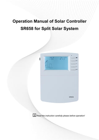
  • 1. Operation Manual of Solar Controller SR658 for Split Solar System Read the instruction carefully please before operation!
  • 2. Operation manual of solar controller SR658 Page 1 of 105 Contents 1. Safety information.....................................................................................................................4 1.1 Installation and commissioning ............................................................................................4 1.2 About this manual...................................................................................................................4 1.3 Liability waiver.........................................................................................................................4 1.4 Important information.............................................................................................................5 1.5 Signal description ...................................................................................................................5 1.6 HMI button ...............................................................................................................................5 1.7 Meaning of icons appeared on the screen.........................................................................6 2 Overview......................................................................................................................................6 2.1 Controller introduction............................................................................................................6 2.2 Delivery list ..............................................................................................................................7 2.3 Technical data .........................................................................................................................7 3. Installation..................................................................................................................................8 3.1 Mounting controller.................................................................................................................8 3.2 Wiring connection...................................................................................................................8 3.3 Terminal connection ...............................................................................................................9 3.4 TF (MicroSD) Card...............................................................................................................13 4. System introduction................................................................................................................14 4.1 Overview of the available systems....................................................................................14 4.2 Description of 19 systems...................................................................................................16 System 1: Standard solar system with 1 tank, 1 collector field...........................................16 System 2: Solar system with 1 tank, 1 collector field, 3-ways valve for tank loading in layers.............................................................................................................................................17 System 3: Solar system with 1 collector filed, 2 tanks and thermal energy transferring between 2 tanks ..........................................................................................................................18 System 4: Standard solar system with heat exchanger control logic.................................19 System 5: Solar system with 1 collector field, 2 tanks, pump -logic control .....................20 System 6: Solar system with 1 collector field, 1 tank, valve logic control .........................21 System 7: Solar system with east/west collector fields, 1 tank...........................................22 System 8: Solar system with east/west collector field, valve logic control, loading in layers.............................................................................................................................................23 System 9: Solar system with east/west collector fields, 2 tanks, valve logic control.......24 System 10: Solar system with east/west collector fields, 1 tank, loading the heating
  • 3. Operation manual of solar controller SR658 Page 2 of 105 return .............................................................................................................................................25 System 11: Solar system with 1 collector field,1 tank, loading the heating return...........26 System 12: Solar system with 1 collector field, 2 tanks, valve logic, heating return loading...........................................................................................................................................27 System 13: Solar system with 1 collector field, 2 tanks, thermal energy transferring.....28 System 14: Solar system with 1 collector field, swimming pool heating ...........................29 System 15: Solar system with 1 collector field, heat exchanger and swimming pool heating...........................................................................................................................................30 System 16: Solar system with 1 collector field, 1 tank, valve and heat exchanger control ........................................................................................................................................................31 System 17: System with 1 tank and solid fuel boiler.............................................................32 System 18: System with 2 tanks, thermal energy transferring and solid fuel boiler ........33 System 19: System with 1 tank, heating return and solid fuel boiler .................................34 4.3 Commissioning .....................................................................................................................35 5. Functions and options............................................................................................................35 5.1 Overview of menu structure................................................................................................35 5.2 Menu operation description ................................................................................................36 5.3 Check value...........................................................................................................................36 6. Menu function and parameter set (for user).......................................................................37 (1)Date (Time/ Date set).......................................................................................................37 (2)THET Timed back-up heating.........................................................................................38 (3)CIRC DHW circuit pump controlled by three time - sections temperature / flow switcher.........................................................................................................................................43 7. Function operation and parameter setting (expertise) .....................................................48 (4)PRSWD password............................................................................................................48 (5)SYS system selection ......................................................................................................49 (6)(7)LOAD/LOAD2 Tank heating set .............................................................................49 (8)(9)COL/COL2 Collector function.................................................................................53 (10)PINTV Swimming pool function....................................................................................59 (11)PUMP Pump control mode............................................................................................60 (12)LLOGI Tank priority logic ...............................................................................................63 (13)COOL Cooling function..................................................................................................67
  • 4. Operation manual of solar controller SR658 Page 3 of 105 (14)HEATX Energy exchange between tanks ..................................................................71 (15)RPH Heating return pipe preheat ................................................................................73 (16)DLHTX Thermal energy transferring between 2 tanks .............................................74 (17)AUX Auxiliary functions .................................................................................................75 (18)MAN Manual mode.........................................................................................................81 (19)BLPR Block protection function....................................................................................82 (20) OTDIS Thermal disinfection function..........................................................................83 (21)OPARR Parallel relay.....................................................................................................85 (22)OHQM Heat quantity measurement............................................................................86 (23)FS Flow meter selection and flow monitor .................................................................89 (24)UNIT Unit switch ..........................................................................................................91 (25)OSDC(SD card).........................................................................................................92 (26)RET Reset........................................................................................................................94 (27)PASS Password set .......................................................................................................95 7. Holiday function.......................................................................................................................95 8. Software of controller upgrade .............................................................................................96 9. Protection function..................................................................................................................97 9.1 Screen protection .................................................................................................................97 9.2 Trouble protection.................................................................................................................97 9.3 Trouble checking...................................................................................................................97 10. Quality Guarantee ..............................................................................................................103 11. Accessories..........................................................................................................................103
  • 5. Operation manual of solar controller SR658 Page 4 of 105 1. Safety information 1.1 Installation and commissioning  When laying wires, please ensure that no damage occurs to any of the constructional fire safety measures presented in the building.  The controller should not be installed in rooms where easily inflammable gas mixtures are present or may occur.  The permissible environmental conditions can’t be exceeded at the site of installation.  Before connecting the device, please make sure that the power supply matches the specifications that controller requires.  All devices connected to the controller must conform to the technical specifications of the controller.  All operations on an open controller are only to be conducted cleared from the power supply. All safety regulations for working on the power supply are valid.  Connecting and / or all operations that require opening the controller (e.g. changing the fuse) are only conducted by specialists. 1.2 About this manual This manual describes the installation, functions and operation of a solar controller. When installing the remaining components e.g. the solar collectors and the tank unit, please be sure to observe the appropriate installation instructions provided by each manufacturer. Installation, electrical connection, commissioning and maintenance of the device may only be performed by trained professional person. The professional person must be familiar with this manual and follow the instructions contained herein. 1.3 Liability waiver The manufacturer can’t monitor the compliance with these instructions or the circumstances and methods used for installation, operation, utilization and maintenance of this controller. Improper installation can cause damages to material and person. This is the reason why we do not take over responsibility and liability for losses, damages or cost that might arise due to improper installation, operation or wrong utilization and maintenance or that occurs in some connection with the aforementioned. Moreover, we do not take over liability for patent infringements or infringements – occurring in connection with the use of this controller on the third parties’ rights. The manufacturer preserves the right to put changes to product, technical data or installation and operation instructions without prior notice. As soon as it becomes evident that safe operation is no longer possible (e.g. visible damage). Please immediate take the device out of operation. Note: ensure that the device can’t be
  • 6. Operation manual of solar controller SR658 Page 5 of 105 accidentally placed into operation. 1.4 Important information We have carefully checked the text and pictures of this manual and provided the best of our knowledge and ideas, however inevitable errors maybe exist. Please note that we cannot guarantee that this manual is given in the integrity of image and text, they are just some examples, and they apply only to our own system. Incorrect, incomplete and erroneous information and the resulting damage we do not take responsibility. 1.5 Signal description Safety indication: Safety instructions in the text are marked with a warning triangle. They indicate measures which can lead to injury of person or safety risks. Operation steps: small triangle “►”is used to indicate operation step. Notes: Contains important information about operation or functions. 1.6 HMI button LED indicator lamp  Controller is operated with the 5 buttons besides the screen  “ " holiday button  “ SET ” button: confirm / selection  “↑” up button: increase the value  “↓” down button: reduce the value  “ESC" button return/ exit: return to previous menu Note: TST is temperature of tank 1 (on screen)
  • 7. Operation manual of solar controller SR658 Page 6 of 105 1.7 Meaning of icons appeared on the screen Icon Meaning Code Icon is lighting Icon is blinking Exceed the maximum temperature of tank SMX Running of tank emergency shutdown function ╋ Running of collector emergency shutdown function CEM Running of collector cooling function OCCO Running of tank cooling function OSTC Running of system cooling function OSYC Activating of anti-freezing function OCFR Running of anti-freezing function OCFR ╋ Activating of collector minimum temperature function OCMI Error of temperature sensor Error of flow sensor ╋ 2 Overview 2.1 Controller introduction  LED large screen display  6 * relay outputs  1 * low voltage relay output for boiler on/off control  8 * sensor inputs  1 * Input for Grundfos Direct Sensor TM (VFS)  1 * Input for (FRT) rotary blade electronic flowmeter  3 * Variable frequency PWM outputs for the speed control of the high efficiency pump
  • 8. Operation manual of solar controller SR658 Page 7 of 105  Data saved on the TF card (Micro SD)  485 communication port for connect communication module (function not available now)  19 systems for choose 2.2 Delivery list  1 * SR658 controller  1 * user manual  2 * screen and expansion  2 * P1000 temperature sensor (φ6*50mm, cable length 1.5meter)  4 * NTC10K temperature sensor (φ6*50mm, cable length 3meter)  1 * clamp bag 2.3 Technical data  Inputs: 2* PT1000 temperature sensors 6* NTC10K, B=3950 temperature sensors 1* Grundfos Direct Sensor (VFS type) 1* Rotary blade electronic flowmeter (FRT)  Output: 3* Electromagnetic relay, Max. current 1A 3* Semiconductor repay, Max. current 1A 1* low voltage relay (on/off signal), boiler on/off control 3* PWM variable frequency output (switchable 0-10V)  Functions: operating hour counter, tube collector function, thermostat function, pump speed control, heat quantity measurement, external heat exchange, swimming pool circuit system, adjustable system parameters and optional functions (menu-driven), balance and diagnostics  Power supply: 100…240V ~ (50…60Hz)  Rated impulse voltage::2.5KV  Data interface : TF (Micro SD)  485 current supply:60mA (function not available now)  Housing:Plastic ABS  Mounting:Wall mounting  Indication / Display: System-Monitoring-Display, for visualization of the systems, LED l display, and background illumination  Operation: 5 push buttons at the front cover  Protection type: IP41
  • 9. Operation manual of solar controller SR658 Page 8 of 105  Protection class: I  Ambient temperature: 0 ... 40 °C  Degree of pollution: 2  Dimensions: 208*158*43mm Note: TF (Micro SD) isn’t included in the delivery list 3. Installation Note: The unit should only be installed in the dry interior rooms. Please separate routing of sensor wires and mains wires. Make sure the controller as well as the system are not exposed to the strong electromagnetic fields. 3.1 Mounting controller Follow the below steps to mount the controller on the wall.  Unscrew the crosshead screw from the cover and remove it along with the cover from the housing.  Mark the upper fastening point on the wall. Drill and fasten the enclosed wall plug and screw leaving the head protruding.  Hang the housing from the upper fastening point and mark the lower fastening points (centers 180 mm).  Drill and insert lower wall plugs.  Fasten the housing to the wall with the lower fastening screw and tighten.  Carry out the electrical wiring in accordance with the terminal allocation  Put the cover on the housing. Attach with the fastening screw. 3.2 Wiring connection According to the way of installation, wire can be connected from hole A on the bottom plate or from hole B, using a suitable tool (like knife) to cut the plastic of A. Note: wires must be fastened by fixing clamps on position C.
  • 10. Operation manual of solar controller SR658 Page 9 of 105 3.3 Terminal connection Note: before opening the housing! Always disconnect the controller from power supply and obey the local electrical supply regulation.  Input terminals T0~T1: PT1000 temperature sensor, for measuring the temperature of collector T2~T7: NTC10K, B=3950 temperature sensor, for measuring temperature of tank and pipe PWM1, PWM2, PWM3: Signal ports for high efficiency pump, detailed connection see below picture HK-A, HK-B: Dry connection on/off signal ports, (HK and HR simultaneously open or close, for boiler heating control)
  • 11. Operation manual of solar controller SR658 Page 10 of 105 Communication port 485:ELA485, for remote control communication( function not available now) FRT:For Rotary blade electronic flowmeter VFS:For Grundfos flowmeter sensor  Advice regarding the installation of temperature sensors: ① Only original factory equipped Pt1000 temperature sensors are approved for using with the collector, it is equipped with 1.5m silicon cable and suitable for all weather conditions, the cable is temperature resistant up to 280oC, connect the temperature sensors to the corresponding terminals with either polarity. ② Only original factory equipped NTC10K, B=3950 temperature sensors are approved for using with tank and pipe, it is equipped with 3m PVC cable, and the cable is temperature resistant up to 105 o C, connect the temperature sensors to the corresponding terminals with either polarity. ③ All sensor cables carry low voltage, and to avoid inductive effects, must not be laid close to 230 Volt or 400 Volt cables (minimum separation of 100mm). ④ If external inductive effects are existed, e.g. from heavy current cables, overhead train cables, transformer substations, radio and television devices, amateur radio stations, microwave devices etc., then the cables to the sensors must be adequately shielded. ⑤ Sensor cables may be extended to a maximum length of ca. 100 meter, when cable’s length is up to 50m, and then 0.75mm 2 cable should be used. When cable’s length is up to 100m, and then 1.5mm 2 cables should be used.  Output terminal Input Ports L, N: for power connection, L: live wire, N: zero wire, protective ground wire Output R1: Semiconductor relays (SCR), designed for pump speed control, Max. Current: 1A Output R2: Semiconductor relays (SCR), designed for pump speed control, Max. Current: 1A Output R3: Semiconductor relays (SCR), designed for pump speed control, Max. Current: 1A
  • 12. Operation manual of solar controller SR658 Page 11 of 105 Output R4: Electromagnetic relays, designed for on/off control of pump or 3-ways electromagnetic valve, Max. Current: 1A Output R5: Electromagnetic relays, designed for on/off control of pump or 3-ways electromagnetic valve, Max. Current: 1A Output HR: Electromagnetic relays, designed for on/off control of back-up heating device, Max. Current: 1A  R4, R5 terminals for 3-ways valve / pump connection Valve with 3 wires Valve with 2 wires Pump connection R4~R5: When it is for control 3 ways electromagnetic valve,(3 is normally close port, 2 is normally open port ,1 is common port) When it is for control pump, (2 is normally open port, 1 is common port)
  • 13. Operation manual of solar controller SR658 Page 12 of 105  Connection with high efficiency pump  Connecting the signal wire from the high-efficiency pump Signal wire 1 from the high-efficiency pump is connected to GND port of controller Signal wire 2 from the high-efficiency pump is connected to PWM1 port of controller Signal wire 3 from the high-efficiency pump is signal wire FB1, it is not connected to FB1 port of controller Some pumps connections are available as above, for example: Wilo Yonos PARA ST15/7.0 PWM2 M Grundfos UPM3 SOLAR 15-75 130 CZA  Note:  High-efficiency pump with 0-10V signal only has 2 signal wires, connected to the corresponding port GND, PWM1 of controller.  Blue wire not always represent for “GND” and brown wire not always represent for “PWM”. ”PWM” from pump must be match for “PWM” from controller.
  • 14. Operation manual of solar controller SR658 Page 13 of 105 ”GND” from pump must be match for “GND” from controller. 3.4 TF (MicroSD) Card  Controller is equipped with a slot for TF (Micro SD) card.  With TF (MicroSD) card, following functions can be carried out  Save the measurement value and parameters value onto the MicroSD TF card. After transferring the data to a computer, the value can be opened and visualized, e. g. in a spreadsheet.  Copy the updated firmware program from computer and install it on the controller via MicroSD card. TF(MicroSD)card slot Note: TF (MicroSD) card is not listed in the standard delivery package, self-purchase if need, more detailed about TF (MicroSD) see paragraph 7 (25)
  • 15. Operation manual of solar controller SR658 Page 14 of 105 4. System introduction 4.1 Overview of the available systems
  • 16. Operation manual of solar controller SR658 Page 15 of 105
  • 17. Operation manual of solar controller SR658 Page 16 of 105 4.2 Description of 19 systems System 1: Standard solar system with 1 tank, 1 collector field Description: The controller calculates the temperature difference between collector sensor T1 and tank sensor T2. If the difference is larger than or identical to the adjusted switch-on temperature difference, the solar circulation pump (R1) will be switched on and the tank will be loaded until the switch-off temperature difference or the maximum tank temperature is reached. Sensor Description Relay Description T0 Temperature of solid fuel boiler (optional) R1 Solar circulation pump T1 Temperature of collector R2 1.CIRC(DHW circulation) T2 Temperature of tank base R3 1. SFB(Solid fuel boiler) T3 Temperature of tank upper (optional one) R4 1. OHDP(Thermal transfer) T4 Sensor for thermostat temperature (optional one) R5 1. TIMER(Timer function) 2. OPARR(Parallel relay) 3. Thermostat function T5 Sensor for DHW temperature or for flow switcher(optional) HR Back-up heating T6 Optional free sensor, undefined(optional) T7 Temperature for thermal energy measurement (optional one)
  • 18. Operation manual of solar controller SR658 Page 17 of 105 System 2: Solar system with 1 tank, 1 collector field, 3-ways valve for tank loading in layers Description: The controller calculates the temperature difference between collector sensor T1 and tank base and upper sensor T2, T3. If the difference is larger than or identical to the adjusted switch-on temperature difference, the solar circulation pump (R1) will be switched on, and simultaneously valve R4 turns to the corresponding tank zone and this zone will be loaded until the switch-off temperature difference or the maximum tank temperature is reached. The priority logic effects prior loading of the upper zone of the tank. Please refer the Paragraph of "LLOGI Tank priority logic" Sensor Description Relay Description T0 Temperature of solid fuel boiler (optional) R1 Solar circulation pump T1 Temperature of collector R2 1.CIRC(DHW circulation) T2 Temperature of tank base R3 1. SFB(Solid fuel boiler) T3 Temperature of tank upper (optional one) R4 1. Valve of solar circuit T4 Sensor for thermostat temperature (optional one) R5 1. TIMER(Timer function) 2. OPARR(Parallel relay) 3. Thermostat function 4. OHDP(Thermal transfer) T5 Sensor for DHW temperature or for flow switcher (optional) HR Back-up heating T6 Optional free sensor, undefined(optional) T7 Temperature for thermal energy measurement (optional)
  • 19. Operation manual of solar controller SR658 Page 18 of 105 System 3: Solar system with 1 collector filed, 2 tanks and thermal energy transferring between 2 tanks Description: The controller calculates the temperature difference between collector sensor T1 and tank 1 base sensor T2. If the differences is larger than or identical to the adjusted switch-on temperature difference, then the solar circulation pump (R1) will be switched on, tank will be loaded until the switch-off temperature difference or the maximum tank temperature is reached. Thermal energy transferring means the other tank (2) is heated, another temperature difference controls the running of pump R2(difference between T3 and T4 temperature.) Please refer the Paragraph of "HEATX Energy exchange between tanks" Sensor Description Relay Description T0 Temperature of solid fuel boiler (optional) R1 Solar circulation pump T1 Temperature of collector R2 Pump for thermal transfer between tank T2 Temperature of tank 1 base R3 1. SFB(Solid fuel boiler) T3 Temperature of tank 1 upper (optional one) R4 1. CIRC(DHW circulation) T4 Temperature of tank 2 R5 1. TIMER(Timer function) 2. OPARR(Parallel relay) 3. Thermostat function 4. OHDP(Thermal transfer ) T5 Sensor for DHW temperature or for flow switcher (optional) HR Back-up heating T6 Optional free sensor, undefined(optional) T7 Temperature for thermal energy measurement (optional)
  • 20. Operation manual of solar controller SR658 Page 19 of 105 System 4: Standard solar system with heat exchanger control logic Description: The controller calculates the temperature difference between collector sensor T1 and tank base sensor T2. If the difference is larger than or identical to the adjusted switch-on temperature difference, then the corresponding solar circulation pump (R1) will be switched on, heat exchanger is heated until the switch-off temperature difference or the maximum exchanger temperature is reached. By using another temperature difference between T4 and T2 controls pump R2 to load tank Note: if sensor T4 is not installed, then when temperature difference between collector T1 and tank T2 is reached, pump R1 and R2 are triggered simultaneously, and pumps are ceased until the switch-off temperature reaches or the maximum exchanger temperature is reached. Sensor Description Relay Description T0 Temperature of solid fuel boiler (optional) R1 Solar circulation pump 1 T1 Temperature of collector R2 Solar circulation pump 2 T2 Temperature of tank base R3 1. SFB(Solid fuel boiler) T3 Temperature of tank upper (optional ) R4 1. CIRC(DHW circulation) T4 Temperature of heat exchanger (optional) R5 1. TIMER(Timer function) 2. OPARR(Parallel relay) 3. Thermostat function 4. OHDP(Thermal transfer ) T5 Sensor for DHW temperature or for flow switcher (optional) HR Back-up heating T6 Optional free sensor, undefined(optional) T7 Temperature for thermal energy measurement (optional)
  • 21. Operation manual of solar controller SR658 Page 20 of 105 System 5: Solar system with 1 collector field, 2 tanks, pump -logic control Description: The controller calculates the temperature difference between collector sensor T1 and tank 1 and tank 2’s base sensor T2 and T4. If any difference is larger than or identical to the adjusted switch-on temperature difference, then the corresponding solar circulation pump (R1 or R2) will be switched on, tank will be loaded until the switch-off temperature difference or the maximum tank temperature is reached. The priority logic effects prior loading of the tank 1. Please refer the Paragraph of "LLOGI Tank priority logic" Sensor Description Relay Description T0 Temperature of solid fuel boiler (optional) R1 Solar circulation pump 1 T1 Temperature of collector R2 Solar circulation pump 2 T2 Temperature of tank 1 base R3 1. SFB(Solid fuel boiler) T3 Temperature of tank 1 upper (optional) R4 1. CIRC ( DHW circulation) T4 Temperature of tank 2 base R5 1. TIMER(Timer function) 2. OPARR(Parallel relay) 3. Thermostat function 4. OHDP ( Thermal transfer ) T5 1. Temperature of tank 2 upper (optional) 2.Sensor for DHW temperature or for flow switcher (optional) T6 Optional free sensor, undefined(optional) T7 Temperature for thermal energy measurement (optional) HR Back-up heating
  • 22. Operation manual of solar controller SR658 Page 21 of 105 System 6: Solar system with 1 collector field, 1 tank, valve logic control Description: The controller calculates the temperature difference between collector sensor T1 and tank 1 and tank 2’s base sensor T2 and T4. If any difference is larger than or identical to the adjusted switch-on temperature difference, then the solar circulation pump (R1) will be switched on, and simultaneously valve R4 turns to the corresponding tank, and this tank will be loaded until the switch-off temperature difference or the maximum tank temperature is reached. The priority logic effects prior loading of the tank 1. Please refer the Paragraph of "LLOGI Tank priority logic" Sensor Description Relay Description T0 Temperature of solid fuel boiler (optional) R1 Solar circulation pump 1 T1 Temperature of collector R2 1. CIRC(DHW circulation) T2 Temperature of tank 1 base R3 1. SFB(Solid fuel boiler) T3 Temperature of tank 1 upper (optional) R4 Valve of solar circuit T4 Temperature of tank 2 base R5 1. TIMER(Timer function) 2. OPARR(Parallel relay) 3. Thermostat function 4. OHDP(Thermal transfer ) T5 1. Temperature of tank 2 upper (optional) 2.Sensor for DHW temperature or for flow switcher (optional) T6 Optional free sensor, undefined(optional) T7 Temperature for thermal energy measurement (optional) HR Back-up heating
  • 23. Operation manual of solar controller SR658 Page 22 of 105 System 7: Solar system with east/west collector fields, 1 tank Description: The controller calculates the temperature difference between east/ west collector sensor T1 and T0 and tank base sensor T2. If any difference is larger than or identical to the adjusted switch-on temperature difference, then solar circulation pump (R1 or R2) will be switched on, and tank will be loaded until the switch-off temperature difference or the maximum tank temperature is reached. Sensor Description Relay Description T0 Temperature of collector 2 R1 Solar circulation pump 1 T1 Temperature of collector 1 R2 Solar circulation pump 2 T2 Temperature of tank base R3 1. SFB(Solid fuel boiler) T3 Temperature of tank upper (optional) R4 1. CIRC(DHW circulation) T4 Sensor for DHW temperature or for flow switcher (optional) R5 1. TIMER(Timer function) 2. OPARR(Parallel relay) 3. Thermostat function 4. OHDP(Thermal transfer ) T5 Temperature of solid fuel boiler(optional) T6 Optional free sensor, undefined(optional) T7 Temperature for thermal energy measurement (optional) HR Back-up heating
  • 24. Operation manual of solar controller SR658 Page 23 of 105 System 8: Solar system with east/west collector field, valve logic control, loading in layers Description: The controller calculates the temperature difference between east/ west collector sensor T1 and T0 and tank base/ upper sensor T2 and T3. If any difference is larger than or identical to the adjusted switch-on temperature difference, then solar circulation pump (R1 or R2) will be switched on, and simultaneously valve R4 turns to the corresponding tank part, and this tank part will be loaded until the switch-off temperature difference or the maximum tank temperature is reached. The priority logic effects prior loading of the upper part of tank. Please refer the Paragraph of "LLOGI Tank priority logic" Sensor Description Relay Description T0 Temperature of collector 2 R1 Solar circulation pump 1 T1 Temperature of collector 1 R2 Solar circulation pump 2 T2 Temperature of tank base R3 1. SFB(Solid fuel boiler) T3 Temperature of tank upper (optional) R4 Valve of solar circuit T4 Sensor for DHW temperature or for flow switcher (optional) R5 1. TIMER(Timer function) 2. OPARR(Parallel relay) 3. Thermostat function 4. OHDP(Thermal transfer ) 5. CIRC(DHW circulation) T5 Temperature of solid fuel boiler(optional) T6 Optional free sensor, undefined(optional) T7 Temperature for thermal energy measurement (optional) HR Back-up heating
  • 25. Operation manual of solar controller SR658 Page 24 of 105 System 9: Solar system with east/west collector fields, 2 tanks, valve logic control Description: The controller calculates the temperature difference between east/ west collector sensor T1 and T0 and 2 tanks base sensor T2 and T4. If any difference is larger than or identical to the adjusted switch-on temperature difference, then solar circulation pump (R1 or R2) will be switched on, and simultaneously valve R4 turns to the corresponding tank, and this tank will be loaded until the switch-off temperature difference or the maximum tank temperature is reached. The priority logic effects prior loading of the tank 1. Please refer the Paragraph of "LLOGI Tank priority logic" Sensor Description Relay Description T0 Temperature of collector 2 R1 Solar circulation pump 1 T1 Temperature of collector 1 R2 Solar circulation pump 2 T2 Temperature of tank 1 base R3 1. SFB(Solid fuel boiler) T3 Temperature of tank 1 upper (optional) R4 Valve of solar circuit T4 Temperature of tank 2 base R5 1. TIMER(Timer function) 2. OPARR(Parallel relay) 3. Thermostat function 4. OHDP(Thermal transfer ) 5. CIRC(DHW circulation) T5 1.Temperature of tank 2 upper (optional) 2.Temperature of solid fuel boiler T6 Sensor for DHW temperature or for flow switcher (optional) T7 Temperature for thermal energy measurement (optional) HR Back-up heating
  • 26. Operation manual of solar controller SR658 Page 25 of 105 System 10: Solar system with east/west collector fields, 1 tank, loading the heating return Description: The controller calculates the temperature difference between east/ west collector sensor T1 and T0 and tank base sensor T2. If any difference is larger than or identical to the adjusted switch-on temperature difference, then solar circulation pump (R1 or R2) will be switched on, and this tank will be loaded until the switch-off temperature difference or the maximum tank temperature is reached. By using another temperature difference between T4 and T5 controls valve R4 to load the heating return flow. Please refer the Paragraph of "RPH Heating return pipe preheat" Sensor Description Relay Description T0 Temperature of collector 2 R1 Solar circulation pump 1 T1 Temperature of collector 1 R2 Solar circulation pump 2 T2 Temperature of tank base R3 1. SFB(Solid fuel boiler) 2. CIRC(DHW circulation T3 Temperature of tank upper (optional) R4 Valve of heating return T4 Temperature of tank middle for heating return (optional) R5 1. TIMER(Timer function) 2. OPARR(Parallel relay) 3. Thermostat function 4. OHDP(Thermal transfer) T5 Temperature of heating return T6 1.Sensor for DHW temperature or for flow switcher (optional) 2.Temperature of solid fuel boiler(optional) T7 Temperature for thermal energy measurement HR Back-up heating
  • 27. Operation manual of solar controller SR658 Page 26 of 105 System 11: Solar system with 1 collector field,1 tank, loading the heating return Description: The controller calculates the temperature difference between collector sensor T1 and tank sensor T2. If the difference is larger than or identical to the adjusted switch-on temperature difference, then solar circulation pump (R1) will be switched on, and this tank will be loaded until the switch-off temperature difference or the maximum tank temperature is reached. By using another temperature difference between T4 and T5 controls valve R4 to load the heating return flow. Please refer the Paragraph of "RPH Heating return pipe preheat" Sensor Description Relay Description T0 Temperature of solid fuel boiler(optional) R1 Solar circulation pump 1 T1 Temperature of collector R2 1.CIRC(DHW circulation) T2 Temperature of tank base R3 1.SFB(Solid fuel boiler) T3 Temperature of tank upper (optional) R4 Valve of heating return T4 Temperature of tank middle for heating return (optional) R5 1. TIMER(Timer function) 2. OPARR(Parallel relay) 3. Thermostat function 4. OHDP(Thermal transfer) T5 Temperature of heating return T6 Sensor for DHW temperature or for flow switcher (optional) T7 Temperature for thermal energy measurement (optional) HR Back-up heating
  • 28. Operation manual of solar controller SR658 Page 27 of 105 System 12: Solar system with 1 collector field, 2 tanks, valve logic, heating return loading Description: The controller calculates the temperature difference between collector sensor T1 and 2 tank’s sensor T2 and T4. If the difference is larger than or identical to the adjusted switch-on temperature difference, then solar circulation pump (R1) will be switched on, and simultaneously valve R4 turns to the corresponding tank, and this tank will be loaded until the switch-off temperature difference or the maximum tank temperature is reached. The priority logic effects prior loading of the tank 1. Please refer the Paragraph of "LLOGI Tank priority logic" By using another temperature difference between T5 and T6 controls valve R5 to load the heating return flow. Please refer the Paragraph of "RPH Heating return pipe preheat" Sensor Description Relay Description T0 Temperature of heating return R1 Solar circulation pump 1 T1 Temperature of collector R2 1. TIMER(Timer function) 2. OPARR(Parallel relay) 3. Thermostat function 4. OHDP(Thermal transfer) T2 Temperature of tank 1 base T3 Temperature of tank 1 upper (optional) T4 Temperature of tank 2 base R3 1.SFB(Solid fuel boiler) 2.CIRC(DHW circulationT5 Temperature of tank 2 upper (optional) R4 Valve of solar circuit T6 Sensor for DHW temperature or for flow switcher (optional) R5 Valve of heating return T7 Temperature for thermal energy measurement (optional) HR Back-up heating
  • 29. Operation manual of solar controller SR658 Page 28 of 105 System 13: Solar system with 1 collector field, 2 tanks, thermal energy transferring Description: The controller calculates the temperature difference between collector sensor T1 and tank 1’s sensor T2. If the difference is larger than or identical to the adjusted switch-on temperature difference, then solar circulation pump (R1) will be switched on, and this tank will be loaded until the switch-off temperature difference or the maximum tank temperature is reached. Thermal energy transferring between 2 tanks: When tank 1’s temperature reaches the switch-on temperature (L1H2O), and temperature of tank 1 is larger than tank 2 (T3>T4), pump R2 is triggered; when tank 1’s temperature drops below its switch off temperature (L1H2F) or temperature of tank 2 rises to the same temperature of tank 1, or temperature of tank 2 reaches its maximum value S2MAX, then pump R2 is stopped When tank 2’s temperature reaches the switch-on temperature (L2H1O), and temperature of tank 2 is larger than tank 1 (T4>T3), pump R3 is triggered; when tank 2’s temperature drops below its switch off temperature (L2H1F) or temperature of tank 1 rises to the same temperature of tank 2, or temperature of tank 1 reaches its maximum value SMAX, then pump R3 is stopped. Please refer the Paragraph of "DLHTX Thermal energy transferring between tanks" Sensor Description Relay Description T1 Temperature of collector R1 Solar circulation pump 1 R2 Heating transfer pump 2 T2 Temperature of tank 1 base R3 Heating transfer pump 3 T3 Temperature of tank 1 upper (optional) R4 1.CIRC(DHW circulation T4 Temperature of tank 2 R5 1.Thermostat function 2. OHDP(Thermal transfer)T5 Sensor for DHW temperature or for flow switcher (optional)
  • 30. Operation manual of solar controller SR658 Page 29 of 105 T6 Optional sensor, undefined(optional) T7 Temperature for thermal energy measurement (optional) HR Back-up heating System 14: Solar system with 1 collector field, swimming pool heating Description: The controller calculates the temperature difference between collector sensor T1 and swimming pool sensor T2. If the difference is larger than or identical to the adjusted switch-on temperature difference, then solar circulation pump (R1) will be switched on, and swimming pool will be loaded until the switch-off temperature difference or the maximum swimming pool temperature is reached. Sensor Description Relay Description T0 Optional sensor, undefined R1 Solar circulation pump T1 Temperature of collector R2 OPARR(Parallel relay) T2 Temperature of swimming pool R3 SFB(Solid fuel boiler) T3 Optional sensor, undefined R4 1.TIMER (Timer heating) 2.Thermal energy transferring T4 Temperature of thermostat (optional) R5 1. Thermostat function T5 Optional sensor, undefined T6 Optional sensor, undefined T7 Temperature for thermal energy measurement (optional) HR Back-up heating
  • 31. Operation manual of solar controller SR658 Page 30 of 105 System 15: Solar system with 1 collector field, heat exchanger and swimming pool heating Description: The controller calculates the temperature difference between collector sensor T1 and heat exchanger sensor T2. If the difference is larger than or identical to the adjusted switch-on temperature difference, then solar circulation pump (R1) will be switched on. When temperature difference between collector sensor T1 and heat exchanger sensor T2 drops to the switch-off temperature difference or the maximum swimming pool temperature is reached, then solar pump R1 is ceased. By using another temperature difference between T4 and T2, R2 can be trigged to heat swimming pool. The controller calculates the temperature difference between heat exchanger sensor T4 and swimming pool T2. If the difference is larger than or identical to the adjusted switch-on temperature difference, then solar circulation pump (R2) will be switched on. When temperature difference between heat exchanger sensor T4 and swimming pool T2 drops to the switch-off temperature difference or the maximum swimming pool (T2) temperature is reached, then solar pump R2 is ceased. Note: when T4 is not installed, then temperature difference between collector T1 and swimming pool T2 is larger than or identical to the adjusted switch-on temperature difference, then solar circulation pump (R1 and R2) will be switched on simultaneously. And when temperature difference between collector sensor T1 and swimming pool T2 drops to the switch-off temperature difference or the maximum swimming pool (T2) temperature is reached, then solar pump R1 and R2 are ceased simultaneously. Sensor Description Relay Description T0 Optional sensor, undefined R1 Solar circulation pump 1 T1 Temperature of collector R2 Solar circulation pump 2 T2 Temperature of swimming pool (optional) R3 SFB(Solid fuel boiler)
  • 32. Operation manual of solar controller SR658 Page 31 of 105 T3 Optional sensor, undefined R4 1.TIMER (Timer heating) 2.OPARR(Parallel relay) 3. Thermostat function T4 Temperature of heat exchanger (optional) R5 1. OHDP(Thermal transfer) T5 Temperature of thermostat (optional) T6 Optional sensor, undefined T7 Temperature for thermal energy measurement (optional) HR Back-up heating System 16: Solar system with 1 collector field, 1 tank, valve and heat exchanger control Description: The controller calculates the temperature difference between collector sensor T1 and tank or heat exchanger sensor (T2, T5). If the difference is larger than or identical to the adjusted switch-on temperature difference, then solar circulation pump (R1) will be switched on. And according to priority logic, valve R4 turns to the tank or heat exchanger, tank and heat exchanger is heated one by one. When temperature difference between collector sensor T1 and tank or heat exchanger sensor(T2,T5)drops to the switch-off temperature difference or the maximum temperature of tank (T2) or swimming pool (T5) is reached, then solar pump R1 is ceased. The priority logic effects prior loading of the tank. Please refer the Paragraph of "LLOGI Tank priority logic" By using another temperature difference between T5 and T4, R2 can be trigged to heat swimming pool. Note: when T5 is not installed, then temperature difference between collector T1 and swimming pool T4 is larger than or identical to the adjusted switch-on temperature difference, then solar circulation pump (R1 and R2) and valve R4 all will be switched on simultaneously. And when temperature difference between collector sensor T1 and swimming pool T4 drops to the switch-off temperature difference or the maximum swimming pool (T4) temperature is reached, then solar pump R1, R2 and valve R4 are ceased simultaneously.
  • 33. Operation manual of solar controller SR658 Page 32 of 105 Sensor Description Relay Description T0 Temperature of solid fuel boiler(optional) R1 Solar circulation pump 1 T1 Temperature of collector R2 Solar circulation pump 2 T2 Temperature of tank base R3 SFB(Solid fuel boiler) T3 Temperature of tank upper(optional) R4 Solar circuit valve T4 Temperature of swimming pool R5 1.OHDP(Thermal transfer) 2.CIRC(DHW circulation) 3. TIMER (Timer heating) 4.OPARR(Parallel relay) 5.Thermostat function T5 Temperature of heat exchanger(optional) T6 Optional sensor, undefined T7 Temperature for thermal energy measurement (optional) HR Back-up heating System 17: System with 1 tank and solid fuel boiler Description: solid fuel boiler function is designed to transfer the thermal energy from solid fuel boiler to tank. The controller calculates the temperature difference between solid fuel boiler sensor T0 and tank sensor (T2 or T3). If the difference is larger than or identical to the adjusted switch-on temperature difference, and meet below two conditions, circulation pump (R1) will be switched on. And when temperature difference between sensor T0 and tank T2 or T3 drops to the switch-off temperature difference, pump R1 is ceased. 1) Temperature of solid fuel boiler is higher than the preset minimum temperature of boiler. 2) Temperature of tank sensor is lower than the preset maximum temperature of tank.
  • 34. Operation manual of solar controller SR658 Page 33 of 105 Sensor Description Relay Description T0 Temperature of solid fuel boiler R1 Solid fuel boiler pump T2 Temperature of tank base R3 CIRC(DHW circulation) T3 Temperature of tank upper(Optional) R4 TIMER (Timer heating) T4 Temperature of thermostat (Optional) R5 Thermostat function HR Back-up heating System 18: System with 2 tanks, thermal energy transferring and solid fuel boiler Description: Thermal energy transferring function is deigned to heat one tank by another tank which has heat source tank/ T4 tank be heated) Please refer the Paragraph of "HEATX Energy exchange between tanks" solid fuel boiler function is designed to transfer the thermal energy from solid fuel boiler to tank. Please refer the Paragraph of "AUX Auxilary function"
  • 35. Operation manual of solar controller SR658 Page 34 of 105 Sensor Description Relay Description T0 Temperature of solid fuel boiler R1 Pump for tank heat transferring T2 Temperature of tank 1 base R2 Solid fuel boiler pump R3 CIRC(DHW circulation) T3 Temperature of tank 1 upper(Optional) R4 TIMER (Timer heating) T4 Temperature of tank 2 base R5 Thermostat function T5 Temperature of tank 2 upper(Optional) HR Back-up heating T6 Sensor for DHW temperature or for flow switcher (optional) System 19: System with 1 tank, heating return and solid fuel boiler Description: Temperature between heat source T4 and heating return T5 is deigned to trigger valve R4. solid fuel boiler function is designed to transfer the thermal energy from solid fuel boiler to tank. Please refer the Paragraph of "RPH Heating return pipe preheat" Please refer the Paragraph of "AUX Auxilary function" Sensor Description Relay Description T0 Temperature of solid fuel boiler R1 Solid fuel boiler pump T2 Temperature of tank base R2 TIMER (Timer heating) R3 CIRC(DHW circulation) T3 Temperature of tank upper(Optional) R4 Valve of heating return T4 Temperature of tank middle for heating return (Optional) R5 Thermostat function
  • 36. Operation manual of solar controller SR658 Page 35 of 105 T5 Temperature of heating return HR Back-up heating T6 Sensor for DHW temperature or for flow switcher (optional) 4.3 Commissioning Before connecting the controller to the mains, ensure system is filled and ready for operation, please connecting all sensors to the input terminals, pumps or valves to the output terminals and fill the system. After power is switch on, the controller runs an initialization phase for 5 seconds, then controller runs a commissioning menu, it leads the user through the most important adjustment channels needed for operating the system. 5. Functions and options 5.1 Overview of menu structure Tanks mutual energy transfer Interval of pool Energy transfer between tanks
  • 37. Operation manual of solar controller SR658 Page 36 of 105 5.2 Menu operation description  Access main menu ►press “SET” button to access main menu ►Press “↑”, “↓” to select menu ►Press “SET” button to enter the submenu  Access submenu ►Press “SET” button to access submenu ►Press “↑”, “↓” button to select submenu to be adjusted ►Press “SET” button to enter this submenu ►Press “SET” button, “OFF” or “ON” blinks on the screen ►Press “↑”, “↓” button, select “ON” to trigger the menu, or select “OFF” to close the menu ►Press “SET” or “ESC” button, to confirm the selection ►Press “↑” button to access the next submenu ►Press “SET” button to access value adjust ►Press “↑”, “↓” button to adjust value ►Press “SET” or “ESC” button, to confirm the value ►Press “ESC” to exit the menu. Note: Enter the menu adjustment interface, if you don’t press any button within 5 minutes, screen will exit the adjustment and turn to the main interface. 5.3 Check value At the normal operation mode, press “↑”, “↓” button, you can view the temperature of collector and tank, pump speed(n1%), accumulated pump running time(hR1),current thermal energy(dKWH) accumulated thermal energy(KWh or MWh), flow rate(L/M), controller running time (DAYS), software version (SW). Under standby status, press “SET” button for 3 seconds, then press “↑”, “↓” button to check the type of pump. Under the checking status, when the digital flow meter is failed, (L/M 0.0) will display on the screen, it is possible to quickly set the flow meter type to a fixed flow rate (mechanical flow meter), doing follow steps: ►Press “↑”, “↓” button, select flow rate, (L/M 0.0) displays. ►Press “SET” button for 3 seconds, beeper sounds “du….” 3 times, and then flow rate is set to a fixed value (read from mechanical flow meter). Electronic flow meter is switched off. Note:
  • 38. Operation manual of solar controller SR658 Page 37 of 105  When sterilization function is running, sterilization time can be checked, when auxiliary function is running, corresponding signal blinks on the screen  Thermal energy is showed as kWh under kWh channel, is showed as MWh under MWh channel, total accumulation of thermal energy produced by solar system is the plus of kWh + MWh  Enter the value check interface, if you don’t press any button within 3 minutes, screen will exit the check interface and turn to main interface. 6. Menu function and parameter set (for user) (1)Date (Time/ Date set) Menu structure Main menu Submenu 1 Submenu 2 Default set Adjust range Adjust step Description DATE Time/date set TIME Hour/minute ADST OFF ON/OFF Summer time on/off YYYY Year MM/DD Month/day  ADST: Switch on/off the summer time function When you deactivate the “summer time function”, controller still can run, “ADST” is only referring directives Europe 200/84/EG, only suitable for Europe union country. Note: In the case power to controller is switched-off, date and time will be remembered in controller for 36 hours. Function set: ►Press “SET” button, select DATE menu ►Press “SET” button, “TIME 00:00” displays on the screen ►Press “SET” button, time zone hour “00” blinks
  • 39. Operation manual of solar controller SR658 Page 38 of 105 ►Press “↑”, “↓” button to adjust hour time ►Press “SET” button, time zone minute “00” blinks ►Press “↑”, “↓” button to adjust minute time ►Press “SET” or “ESC” button, to confirm the setting ►Press “↑” button, “ADST OFF” displays on the screen (summer time) ►Press “SET” button, “OFF” blinks ►Press “↑”, “↓” button to activate summer timer function ►Press “SET” or “ESC” button, to confirm the setting ►Press “↑” button, “YYYY 2015” displays on the screen ►Press “SET” button, “2015” blinks ►Press “↑”, “↓” button to adjust year ►Press “SET” or “ESC” button, to confirm the setting ►Press “↑” button, “MM 01” displays on the screen ►Press “SET” button, “01” blinks ►Press “↑”, “↓” button to adjust month ►Press “SET” or “ESC” button, to confirm the setting ►Press “↑” button, “DD 01” displays on the screen ►Press “SET” button, “01” blinks ►Press “↑”, “↓” button to adjust day ►Press “SET” or “ESC” button, to confirm the setting (2)THET Timed back-up heating Timed heating An electrical back-up heater is possible to be installed in a solar system, controller can provide automatic thermostat control function, when tank temperature T3 drops below the preset switch – on temperature of this function, electrical heater(HR) will be triggered and when tank temperature T3 rises to the preset switch-off temperature, electrical heater(HR) is stopped. Two heating modes are available:  Electrical heater as back-up heat producer (ELECT)  Boiler as back-up heat producer (BOILE) Three time - sections can be set for back-up heat producer
  • 40. Operation manual of solar controller SR658 Page 39 of 105 Factory default set:  The first time - section of heating starts at 04:00and stops at 05:00 a.m.  The second time - section of heating starts at 10:00 and stops at 10:00 a.m.  The third time - section of heating starts at 17:00 and stops at 22:00 p.m.  For all time - section, default temperature for control back-up heating is triggered at temperature of 40 o C, and stopped at temperature of 50 o C.  If it is needed to deactivate the back-up heating function in one time - section, then just set the start time and stop time with a same value, for example, for the second-time - section, the start time is 10:00 a.m, and the stop time is also 10:00 a.m.  Within three time - sections, the adjust range of the switch-on temperature is 0 o C ~ (OFF-2 o C), and the switch-off temperature is (ON+2 o C) ~ 95 o C. SMT: Intelligent heating At the case that solar energy is insufficient to heat the tank, to ensure user has sufficient hot water, controller will check the temperature of tank automatically at the pre-set time - section, if tank’s temperature is not reached to the desired temperature, then back-up heat producer will be triggered, and when tank’s temperature rises to the desired value, then back-up heat producer is stopped. Factory set (unchangeable) of SMT function:  Default at 13:00 of the first time - section to trigger the back-up heat device to heat tank to 30 o C,  Default at 14:00 of the second time - section to trigger the back-up heat device to heat tank to 35 o C,  Default at 15:00 of the third time - section to trigger the back-up heat device to heat tank to 40 o C,  Default at 16:00 of the forth time - section to trigger the back-up heat device to heat tank to 45 o C,  Default at 17:00 of the fifth time - section to trigger the back-up heat device to heat tank to 50 o C.
  • 41. Operation manual of solar controller SR658 Page 40 of 105  Diagram of back-up boiler connection (BOILE) ON/OFF signal AC100-220V (customized available) If boiler is selected as back-up heat producer, output HK and HR is controlled by T3 or T2(Optional). When T3 or T2(Optional) is reached to the switch-on temperature of back-up heating function, then back-up heating output HK and HR are triggered, when T3 or T2(Optional) is exceeded the switch-off temperature of back-up heating function, then back-up heating output HK and HR are closed. Note: if electrical heater is selected as back-up heat producer, then according to the power heater, an appropriate AC contactor and safety protection device should be installed, we recommend to install the accessory “SR802” (see accessories in paragraph 11) Menu structure
  • 42. Operation manual of solar controller SR658 Page 41 of 105 Main menu Submenu 1 Submenu 2 Default set Adjust range Adjust step THET Timed heating function ELECT OFF ON/OFF Electrical back-up heat producer BOILE OFF ON/OFF Boiler as back-up heater producer THTS T3 T2,T3 Selection of the target sensor for timed heating function SMT OFF ON/OFF Intelligent heating tH1O 04:00/40℃ 00:00-23:59/0.0-93℃ Start time and switch-on temperature for the first time- section tH1F 05:00/50℃ 00:00-23:59/2-95℃ Close time and switch-off temperature for the first time- section t H2O 10:00/40℃ 00:00-23:59/0.0-93℃ Start time and switch-on temperature for the second time - section tH2F 10:00/50℃ 00:00-23:59/2-95℃ Close time and switch-off temperature for the second time - section tH3O 17:00/50℃ 00:00-23:59/0.0-93℃ Start time and switch-on temperature for the third time- section tH3F 22:00/55℃ 00:00-23:59/2-95℃ Close time and switch-off temperature for the third time- section Function set: ►Press “SET” button, access main menu, press “↑” button to select THET timed heating menu ►Press “SET” button, access the submenu of setting interface, “ELECT” displays on the screen (take ELECT as example) ►Press “SET” button, “ELECT OFF” displays ►Press “SET” button, “OFF” blinks ►Press “↑”, “↓” button to activate the function, “ELECT ON” displays on the screen ►Press “SET” or “ESC” button, to confirm the setting ►Press “↑”, to access sensor selection window, “THTS T3” displays on the screen ►Press “SET” button, “T3” blinks ►Press “↑”, “↓” button to select the available sensor
  • 43. Operation manual of solar controller SR658 Page 42 of 105 ►Press “SET” or “ESC” button, to confirm the setting ►Press “↑”, to access the intelligent heating window, “SMT OFF” displays on the screen ►Press “SET” button, “OFF” blinks ►Press “↑”, “↓” button to activate the intelligent heating function, “SMT ON” displays on the screen ►Press “SET” or “ESC” button, to confirm the setting ►Press “↑”, to access the window of the start time and switch-on temperature setting of heating in the first-time - section, “tH1O 04:00” displays on the screen ►Press “SET” button, hour time zone “04” blinks ►Press “↑”, “↓” button to set the hour of the start time of heating in the first-time - section ►Press “SET” button, minute time zone “00” blinks ►Press “↑”, “↓” button to set the minute of the start time of heating in the first-time - section ►Press “↑”, to access the switch-on temperature of heating in the first-time - section, “tH1O 40 o C” displays on the screen ►Press “SET” button, temperature “40 o C” blinks ►Press “↑”, “↓” button to adjust the switch-on temperature of heating in the first-time - section ►Press “SET” or “ESC” button, to confirm the setting ►Press “↑”, to access the window of the close time and switch-off temperature setting of heating in the first-time - section, “tH1F 05:00” displays on the screen ►Press “SET” button, hour time zone “05” blinks ►Press “↑”, “↓” button to set the hour of the close time of heating in the first-time - section ►Press “SET” button, minute time zone “00” blinks ►Press “↑”, “↓” button to set the minute of the close time of heating in the first-time - section ►Press “↑”, to access the switch-off temperature of heating in the first-time - section, “tH1F 45 o C” displays on the screen ►Press “SET” button, temperature “45 o C” blinks ►Press “↑”, “↓” button to adjust the switch-off temperature of heating in the first-time - section ►Press “SET” or “ESC” button, to confirm the setting ►Press “↑”, to access the window of the start time and switch-on temperature setting for back-up heating in the second time - section, same steps like above description to set the
  • 44. Operation manual of solar controller SR658 Page 43 of 105 parameters for second and third time - sections. When the icon of the timed heating blinks on the screen, it indicates the back-up heating is activated. Note: meaning of timed heating icon in different status.  Within the time - section, the icon of back-up heating is lighted.  Outside the time - section, the icon of back-up heating is not displayed. (3)CIRC DHW circuit pump controlled by three time - sections temperature / flow switcher (According the different selected system, see paragraph 4.2, the function will assign to different object sensors and output ports) Function description: This function is designed to get warm water quickly when customer open the stopcock. In the case stopcock is closed, hot water pipe is also used as the circuit pipe. Several hot water circuit supply modes are available, for example, 24 hour circuit mode, timed circuit mode, time and temperature control mode etc. if these modes are not optimized design, it may cause unnecessary energy waste. For using this function, an extra circuit pump RX or a flow switcher or a temperature sensor (mounted on the hot water return pipe (TX)) should be installed in the system. (and due to the solar system difference, output relay or sensor input used for circuit pump RX and temperature sensor TX may be different also, see detailed in paragraph 4.2) Note: 1. for 2 DHW control modes, only one mode can be selected from three time - sections/temperature control mode and three time - sections /flow switcher control mode, 2. for 2 DHW control modes, three time - sections/temperature control mode and three time - sections /flow switcher control mode, their parameter adjust steps of two control mode are same.  Three time - sections / temperature control mode TEMP Within the time - section (default: DHW temperature is less than 40 o C, DHW circuit pump is trigger, when temperature rises to 45 o C, DHW circuit pump is stopped). Trigger on conditions of temperature controlled DHW circuit pump (STAT):
  • 45. Operation manual of solar controller SR658 Page 44 of 105 when tank temperature (T2 or T3) is 2 o C higher than the preset switch-off temperature of this function, DHW pump just can be triggered. Default time - section set:  The first time - section: start at 05:00 and stops at 07:00a.m  The second time - section: starts at 11:00 and stops at 13:00  The third time - section: starts at 17:00 and stops at 22:00 p.m.  Three time - sections / flow switcher control mode CYCFS Function description: Open the stopcock, water flows through pipe, a flow signal is felt by a flow switch which is mounted on the cold-water pipe and sent to the controller, and then controller will trigger the DHW circuit pump (RX) and it pumps hot water from tank to the circuit pipe. The running time of circuit pump is adjustable, when the preset time runs out, pump stops. This stopcock seems like a remote controller to control the running of circuit pump. This operation mode is an environment-friendly, energy-saving control solution. Open the stopcock for a shortly time, the flow switch which is mounted on the cold flow pipe of tank will feel the flow signal, and then controller will trigger the circuit pump RX, and pump will feed hot water from tank to the pipe. Then when you re-open the stopcock, hot water flows out immediately. Once the pump’s running time finishes, then pump is stopped. When hot water is not used, to avoid the heat releasing through pipe due to the running of circuit pump, controller will stop the pump after the pre-set running time. To avoid the pump being re-triggered just after it stopped, parameter “rest time” is used for this control. Open the stopcock within a pre-set time - section, pump running as the default design: pump running for every three minutes and then rest for 15minutes (the adjustable range of the running time is 1-30 MIN and the rest time is 0-60MIN) Flow switch To TX input
  • 46. Operation manual of solar controller SR658 Page 45 of 105 Note:  Installed a check valve to avoid the water which is from tank mixing with water from circuit pipe.  If the stop time is set with value 0 minute, then when flow switch feels the flow and thus to trigger the pump, pump will run for the whole time - section. And when the stopcock is closed, pump is stopped automatically. Default time - section set:  The first time - section: start at 05:00 and stops at 07:00a.m  The second time - section: starts at 11:00 and stops at 13:00  The third time - section: starts at 17:00 and stops at 22:00 p.m.  Flow switch fitting: Material of fitting: brass House: plastic Connection: G3/4 Reed of flow switch: Max 300V DC/1A Note:  Noting the flow direction indicated on the flow switch!  Flow switch is not included in the delivery list of this controller, please buy it separately. Menu structure
  • 47. Operation manual of solar controller SR658 Page 46 of 105 Main menu Submen u 1 Submen u 2 Default set Adjust range Adjust step Main menu CIRC DHW circuit function TCYC OFF ON/OFF ON/OFF DHW circuit function TEMP OFF ON/OFF Temperature control the DHW circuit pump CYCFS ON ON/OFF Flow control the DHW circuit pump STAT ON ON/OFF Trigger condition of DHW circuit pump Tank temperature (T3 or T2) is 2 o C higher than the switch-off temperature CYCO 40℃/3min 5-53℃/1-30min 0.5 ℃ /1min Switch-on temperature or running time CYCF 45 ℃ /15min 7-55℃/0-60min 0.5 ℃ /1min Switch-off temperature or the rest time t C1O 05:00 00:00-23:59 Start time of the first time- section t C1F 07:00 00:00-23:59 Close time of the first time- section t C2O 11:00 00:00-23:59 Start time of the second time- section t C2F 13:00 00:00-23:59 Close time of the second time - section t C3O 17:00 00:00-23:59 Start time of the third time- section t C3F 22:00 00:00-23:59 Close time of the third time - section Function set: (take DHW three time - sections temperature control mode as example) ►Press “SET” button, select main menu CIRC ►Press “SET” button, “TCYC” displays on the screen ►Press “SET” button, “TCYC OFF” displays ►Press “SET” button, “OFF” blinks ►Press “↑”, “↓” button to activate the function, “TCYC ON” displays on the screen ►Press “SET” or “ESC” button, to confirm the setting ►Press “↑”, “TEMP OFF” displays on the screen (three time - sections temperature control) ►Press “SET” button, “OFF” blinks ►Press “↑”, “↓” button to activate the function, “TEMP ON” displays on the screen ►Press “SET” or “ESC” button, to confirm the setting
  • 48. Operation manual of solar controller SR658 Page 47 of 105 ►Press “↑”, “CYCFS ON” displays on the screen (three time - sections flow control, default activated) ►Press “SET” button, “ON” blinks ►Press “↑”, “↓” button to activate the function, “CYCFS OFF” displays on the screen ►Press “SET” or “ESC” button, to confirm the setting ►Press “↑”, “STAT ON” displays on the screen (start condition of the temperature control, this function is only available when the temperature control mode is activated, under the flow control mode, this function is invalid) ►Press “SET” button, “ON” blinks (default set) ►Press “↑”, “↓” button to activate the function, “STAT OFF” displays on the screen ►Press “SET” or “ESC” button, to confirm the setting ►Press “↑”, “CYCO 40 o C” displays on the screen ( if flow control CYCFS ON, then here displays “CYCO 03Min”, here take temperature as example) ►Press “SET” button, “40 o C” blinks ►Press “↑”, “↓” button to adjust the switch-on temperature of DHW circuit pump, adjustable range 0 o C ~ (OFF-2 o C) ►Press “SET” or “ESC” button, to confirm the setting ►Press “↑”, “CYCF 45 o C” displays on the screen ►Press “SET” button, “45 o C” blinks ►Press “↑”, “↓” button to adjust the switch-off temperature of DHW circuit pump, adjustable range (ON+2 o C) ~ OFF ►Press “SET” or “ESC” button, to confirm the setting ►Press “↑”, “tC1O 05:00” displays on the screen, to set the start time of the first time-section. ►Press “SET” button, hour time “05” blinks ►Press “↑”, “↓” button to adjust time hour of the start time of the first time-section ►Press “SET” button, minute time “00” blinks ►Press “↑”, “↓” button to adjust time minute of the start time of the first time-section ►Press “SET” or “ESC” button, to confirm the setting ►Press “↑”, “tC1F 07:00” displays on the screen, to set the close time of the first time-section.
  • 49. Operation manual of solar controller SR658 Page 48 of 105 ►Press “SET” button, hour time “07” blinks ►Press “↑”, “↓” button to adjust time hour of the close time of the first time-section ►Press “SET” button, minute time “00” blinks ►Press “↑”, “↓” button to adjust time minute of the close time of the first time-section ►Press “SET” or “ESC” button, to confirm the setting ►Press “↑”, to access the setting of the start time of the second time-section, doing like above descript steps to set the start and close time of second and third time -section. If it is needed to close one time - section, then just set the start time and close time with a same time. (example: at 10:00 start circuit, and at 10:00 close the circuit) 7. Function operation and parameter setting (expertise) (4)PRSWD password Menu structure Main menu Default set Adjust range Description PRSWD 0000 Enter password Press ”SET” button access the main menu, press“↑” and select “PRSWD 0000”. Function set: ►Press “SET” button, the left first digital blinks to ask for entering the password, default password is “0000” ►Press “↑”, “↓” button to enter the first digital ►Press “SET” button, the second digital blinks ►Press “↑”, “↓” button to enter the second digital ►Press “SET” button, the third digital blinks ►Press “↑”, “↓” button to enter the third digital ►Press “SET” button, the forth digital blinks ►Press “↑”, “↓” button to enter the forth digital ►Press “SET” to access the main menu Through the password to limit the customer right to set some important parameters, and four
  • 50. Operation manual of solar controller SR658 Page 49 of 105 digitals re required to enter, default password is “0000”. If no password is reset, then please press “SET” five times to access main menu directly. (5)SYS system selection Main menu Main menu Default set Adjust range Description SYS System 1 System 1-19 System selection For every system, there are many pre-programmed options and setting, they can be activated or changed according the system requirement. There are 19 systems can be selected. ►Press “SET” button to select main menu “SYS” ►Press “SET” button, “SYS 1” displays on the screen ►Press “SET” button, “1” blinks ►Press “↑”, “↓” button to select system ►Press “SET” or “ESC” button, to confirm the setting (6)(7)LOAD/LOAD2 Tank heating set Function description:  △T DT Temperature difference The controller works with a standard differential control logic. If the temperature reaches or exceeds the switch-on temperature difference (DTO), the pump switches on. When the temperature difference reaches or falls below the adjusted switch-off temperature difference (DTF), the respective relay switches off. Note: The switch-on temperature difference must be 0.5 K higher than the switch-off temperature difference. The set temperature difference must be at least 0.5 K higher than the switch-on temperature difference.
  • 51. Operation manual of solar controller SR658 Page 50 of 105 Note: In systems with 2 tanks or tank loading in layers, 2 separate menus (LOAD and LOAD 2) will be displayed.  Speed control If the temperature reaches or exceeds the switch-on temperature difference, the pump switches on at 100% speed for 10s. Then, the speed is reduced to the minimum pump speed value. If the temperature difference reaches the set temperature difference DTS, the pump speed increases by one step (10%). The response of the controller can be adapted via the parameter RIS. If the difference increases by the adjustable rise value RIS, the pump speed increases by 10% until the maximum pump speed of 100% is reached. If the temperature difference decreases by the adjustable rise value RIS, pump speed will be decreased by one step 10%. Note: To enable speed control, the corresponding pump has to be set to (MIN, MAX) and relay control has to be set to (PULS, PSOL, PHEA or 0-10 V) (under adjustment menu PUMP).  SMAX Maximum tank temperature protection set If the tank temperature reaches the pre-set maximum temperature, the tank will no longer be loaded to avoid damage caused by overheating. If the maximum tank temperature is exceeded, Max icon is displayed. The sensor for tank maximum limitation (SMAXS) can be selected. The maximum limitation always refers to the sensor selected. The switch-on hysteresis (HYST) is selectable. Default is 2 o C,for example, when tank maximum temperature is set to 70 o C, then at 68 o C, Maximum tank temperature protection function is deactivated automatically. Note: In systems with 2 tanks or tanks loading in layers, 2 separate menus (LOAD and LOAD 2) will be displayed.
  • 52. Operation manual of solar controller SR658 Page 51 of 105 Menu structure Main menu Submenu Default Set Adjust range Adjust step Main menu LOAD Tank 1 loading set DTO 6K 1-50K 0.5K Switch - on temperature of tank 1 DTF 4K 0.5-49.5K 0.5K Switch - off temperature of tank 1 DTS 10K 1.5-50K 0.5K Temperature difference for pump speed control RIS 2K 1-20K 1K Temperature increase rate for pump speed control SMAX 70℃ 4-95℃ 1℃ Maximum temperature of tank 1 SMAXS T2 T2.T3 Sensor select for maximum temperature of tank 1 HYST 2K 0.1-10K 0.1K Temperature hysteresis of maximum temperature of tank 1 LOAD2 Tank 2 loading set DT2O 6K 1-50K 0.5K Switch - on temperature of tank 2 DT2F 4K 0.5-49.5K 0.5K Switch - off temperature of tank 2 DT2S 10K 1.5-50K 0.5K Temperature difference for pump speed control of tank 2 RIS2 2K 1-20K 1K Temperature increase rate of pump speed control of tank 2 S2MAX 70℃ 4-95℃ 1℃ Maximum temperature of tank 2 SMAXS T4 T4.T5 Sensor select for maximum temperature of tank 2 HYST2 2K 0.1-10K 0.1K Temperature hysteresis of maximum temperature of tank 2
  • 53. Operation manual of solar controller SR658 Page 52 of 105 Function set: ►Press “SET” button to select main menu “LOAD” ►Press “SET” button, “DTO 6K” displays on the screen ►Press “SET” button, “6K” blinks ►Press “↑”, “↓” button to adjust the switch-on temperature difference of the circuit pump. ►Press “SET” or “ESC” button, to confirm the setting ►Press “↑” button, “DTF 4K” display on the screen ►Press “SET” button, “4K” blinks ►Press “↑”, “↓” button to adjust the switch-off temperature difference of the circuit pump. ►Press “SET” or “ESC” button, to confirm the setting ►Press “↑” button, “DTS 10K” display on the screen ►Press “SET” button, “10K” blinks ►Press “↑”, “↓” button to adjust the standard temperature difference of the circuit pump. ►Press “SET” or “ESC” button, to confirm the setting ►Press “↑” button, “RIS 2K” display on the screen ►Press “SET” button, “2K” blinks ►Press “↑”, “↓” button to adjust the temperature difference increase rate of the circuit pump. ►Press “SET” or “ESC” button, to confirm the setting ►Press “↑” button, “SMAX 70 o C” display on the screen ►Press “SET” button, “70 o C” blinks ►Press “↑”, “↓” button to adjust the maximum temperature of tank ►Press “SET” or “ESC” button, to confirm the setting ►Press “↑” button, “SMAXS T2” display on the screen ►Press “SET” button, “T2” blinks ►Press “↑”, “↓” button to select sensor used for measure the maximum temperature of tank. ►Press “SET” or “ESC” button, to confirm the setting ►Press “↑” button, “HYST 2K” display on the screen ►Press “SET” button, “2K” blinks
  • 54. Operation manual of solar controller SR658 Page 53 of 105 ►Press “↑”, “↓” button to adjust the hysteresis temperature of the maximum temperature of tank ►Press “SET” or “ESC” button, to confirm the setting Load 2 function is set same like above steps. (8)(9)COL/COL2 Collector function Function description:  OCEM (2) Collector emergency shutdown When the collector temperature exceeds the adjusted collector emergency temperature, Then solar pump R1(2) switches off to protect the system components against overheating (collector emergency shutdown). If the maximum collector temperature is exceeded OCEM, Warning icon is displayed. Note: In systems with east- / west collectors, 2 separate menus (COL and COL 2) will be displayed. Warning! Risk of injury! Risk of system damage by pressure surge! If water is used as the heat transfer fluid in pressure systems, water will boil at 100 °C. Do not set the collector limit temperature higher than 95 °C.  OCCO (2) Collector cooling The collector cooling function is designed to keep the temperature increase of collector within the operating range by heat the tank. If the tank temperature reaches 95 °C, this function will switch off the pump due to safety of system. When the tank temperature exceeds the pre-set maximum tank temperature, then solar pump is switched off. And then collector temperature may rise, if the collector temperature rises to its maximum temperature, the solar pump is switched on again to transfer the energy from collector to tank, pump is running until the collector temperature falls below the maximum collector temperature, in this heating process, tank temperature may exceed its maximum temperature, but only up to 95°C (emergency shutdown of the tank), both icons are blinks on the screen. and then pump is stopped. If the collector cooling is activated, is displayed. This function is only available when the system cooling function (OSYC) and the heat transfer function(OHDP) are deactivated.
  • 55. Operation manual of solar controller SR658 Page 54 of 105 In systems with east- / west collectors two separate menus (COL and COL 2) will be displayed.  OCMI (2) Collector minimum temperature The minimum collector temperature is the lowest switch-on temperature for triggering the solar pump R1(2), If the collector temperature falls below the minimum temperature, is displayed.  OCFR (2) Collector antifreeze function When the collector temperature falls below the switch-on temperature CFRO of antifreeze function, this function activates the solar pump to circuit system between collector and tank. This will protect the fluid against freezing or coagulating. If collector temperature rises and exceeds the switch-off temperature CFRF of anti-freeze function, the solar pump will be switched off. If collector antifreeze function is activated, is displayed on the screen. If collector antifreeze function is running, are blinks on the screen. Note: In systems with east- / west collectors 2 separate menus (COL and COL 2) will be displayed. Note: Since this function uses the limited heat quantity of the tank, the antifreeze function should be used only in regions with few days of temperatures around the freezing point.  OTCO (2) Tube collector function This function is used for improving the switch-on behavior in systems with non-ideal sensor positions (e. g. with some tube collectors). This function operates within a pre-set time - section. It activates the collector circuit pump R1(2) intermittently to compensate for the delayed temperature measurement caused by poor sensor position. If the runtime is set to more than 10s, the pump will run at 100% speed during the first 10s,
  • 56. Operation manual of solar controller SR658 Page 55 of 105 and pump will run at the minimum speed during the remaining runtime. If the collector sensor is defective, this function will be switched off. In 2-collector fields systems, the tube collector function is available for each individual collector field. In 2-collector fields systems, the tube collector function will affect the inactive collector field only. The solar pump of the active collector field will remain switched on until the switch-off conditions are fulfilled. Menu structure Main menu Submen u 1 Submen u 2 Default Set Adjust range Adjust step Main menu COL Collector function OCEM ON Emergency shutdown function of collector 1 CEM 130℃ 80-200℃ 1℃ Switch-off temperature difference of emergency shutdown of collector 1 (hysteresis 10 o C) OCCO OFF Collector 1 cooling function CMAX 110℃ 70-160℃ 1℃ Collector 1 cooling temperature (hysteresis 5 o C) OCMI OFF Minimum temperature function of collector 1
  • 57. Operation manual of solar controller SR658 Page 56 of 105 CMIN 10℃ 10-90℃ 1℃ Minimum temperature of collector 1 OCFR OFF Anti-freeze function of collector 1 CFRO 4℃ -40-8℃ 0.5℃ Switch-on temperature of anti-freeze function of collector 1 CFRF 5℃ -39-9℃ 0.5℃ Switch-off temperature of anti-freeze function of collector 1 OTCO OFF Tube collector function 1 TCST 07:00 00:00-23:00 1min Start time of tube collector function 1 TCEN 19:00 00:00-23:00 1min Close time of tube collector function 1 TCRU 30s 30-300s 1s Runtime of tube collector function 1 TCIN 30min 5-60min 1min Stop time of tube collector function 1 Main menu Submen u 1 Submen u 2 Default Set Adjust range Adjust step Main menu COL2 Collector 2 function OCEM2 ON Emergency shutdown function of collector 2 CEM2 130℃ 80-200℃ 1℃ Switch-off temperature difference of emergency shutdown of collector 2 (hysteresis 20 o C) OCCO2 OFF Collector 2 cooling function CMAX2 110℃ 70-160℃ 1℃ Collector 2 cooling temperature (hysteresis 5 o C) OCMI2 OFF Minimum temperature function of collector 2 CMIN2 10℃ 10-90℃ 1℃ Minimum temperature of collector 2 OCFR2 OFF Anti-freeze function of collector 2 CFRO2 4℃ -40-8℃ 0.5℃ Switch-on temperature of anti-freeze function of collector 2 CFRF2 5℃ -39-9℃ 0.5℃ Switch-off temperature of anti-freeze function of collector 2 OTCO2 OFF Tube collector function 2 TCST2 07:00 00:00-23:00 1min Start time of tube collector function 2 TCEN2 19:00 00:00-23:00 1min Close time of tube collector function 2 TCRU2 30s 30-300s 1s Runtime of tube collector function 2 TCIN2 30min 5-60min 1min Stop time of tube collector function 2 Function setting: OCEM (Collector emergency shutdown function) ►Press “SET” button to select main menu “COL” ►Press “SET” button, “OCEM” displays on the screen
  • 58. Operation manual of solar controller SR658 Page 57 of 105 ►Press “SET” button, “OCEM ON” displays on the screen. ►Press “SET” button, “ON” blinks If to close the function, then press “↑”, “↓” to switch to “OFF” ►Press “SET” or “ESC” button, to confirm the setting ►Press “↑”, “CEM 130 o C” displays on the screen ►Press “SET” button, “130 o C” blinks ►Press “↑”, “↓” button to adjust the switch-off temperature of the collector emergency shutdown function ►Press “SET” or “ESC” button, to confirm the setting ►Press “ESC” button to return to the previous menu OCCO (Collector cooling function) setting ►Press “↑”, “OCCO” displays on the screen ►Press “SET” button, “OCCO OFF” displays on the screen ►Press “SET” button, “OFF” blinks ►Press “↑”, “↓” button to activate this function, “OCCO ON” displays on the screen ►Press “↑”, “CMAX 110 o C” displays on the screen ►Press “SET” button, “110 o C” blinks ►Press “↑”, “↓” button to adjust the collector cooling temperature ►Press “SET” or “ESC” button, to confirm the setting ►Press “ESC” button to return to the previous menu OCMI (Minimum collector temperature) setting ►Press “↑”, “OCMI” displays on the screen ►Press “SET” button, “OCMI OFF” displays on the screen ►Press “SET” button, “OFF” blinks ►Press “↑”, “↓” button to activate this function, “OCMI ON” displays on the screen ►Press “↑”, “CMIN 10 o C” displays on the screen ►Press “SET” button, “10 o C” blinks ►Press “↑”, “↓” button to adjust the collector minimum temperature ►Press “SET” or “ESC” button, to confirm the setting ►Press “ESC” button to return to the previous menu OCFR (Anti-freezing function) setting ►Press “↑”, “OCFR” displays on the screen
  • 59. Operation manual of solar controller SR658 Page 58 of 105 ►Press “SET” button, “OCFR OFF” displays on the screen ►Press “SET” button, “OFF” blinks ►Press “↑”, “↓” button to activate this function, “OCFR ON” displays on the screen ►Press “↑”, “CFRO 4 o C” displays on the screen ►Press “SET” button, “4 o C” blinks ►Press “↑”, “↓” button to adjust the switch-on temperature of anti-freezing function ►Press “SET” or “ESC” button, to confirm the setting ►Press “↑”, “↓” button to activate this function, “OCFR ON” displays on the screen ►Press “↑”, “CFRF 5 o C” displays on the screen ►Press “SET” button, “5 o C” blinks ►Press “↑”, “↓” button to adjust the switch-off temperature of anti-freezing function ►Press “SET” or “ESC” button, to confirm the setting ►Press “ESC” button to return to the previous menu OTCO (Tube collector function) se ►Press “↑”, “OTCO” displays on the screen ►Press “SET” button, “OTCO OFF” displays on the screen ►Press “SET” button, “OFF” blinks ►Press “↑”, “↓” button to activate this function, “OTCO ON” displays on the screen ►Press “↑”, “TCST 07:00” displays on the screen ►Press “SET” button, hour “07” blinks ►Press “↑”, “↓” button to adjust time hour of this function ►Press “SET” button, minute “00” blinks ►Press “↑”, “↓” button to adjust time minute of this function ►Press “SET” or “ESC” button, to confirm the setting ►Press “↑”, “TCEN 19:00” displays on the screen ►Press “SET” button, hour “19” blinks ►Press “↑”, “↓” button to adjust time hour of this function ►Press “SET” button, minute “00” blinks ►Press “↑”, “↓” button to adjust time minute of this function ►Press “SET” or “ESC” button, to confirm the setting ►Press “↑”, “TCRU 30” displays on the screen ►Press “SET” button, runtime “30” blinks
  • 60. Operation manual of solar controller SR658 Page 59 of 105 ►Press “↑”, “↓” button to adjust the runtime (unit: second) ►Press “SET” or “ESC” button, to confirm the setting ►Press “↑”, “TCIN 30Min” displays on the screen ►Press “SET” button, runtime “30” blinks ►Press “↑”, “↓” button to adjust the stop time (unit: second) ►Press “SET” or “ESC” button, to confirm the setting ►Press “ESC” button to return to the previous menu (10)PINTV Swimming pool function This function is designed to improve the operation of swimming pool system, in which sensor position is not ideal. This function operates within a pre-set time - section. It activates the swimming pool circuit pump R1 or R2 intermittently to compensate for the delayed temperature measurement caused by poor sensor position. If the runtime is set to more than 10s, the pump will run at 100% speed during the first 10s, and pump will run at the minimum speed during the remaining runtime. Menu structure Main menu Submenu Default set Adjust range Adjust step Description PINTV Swimming pool function tPST 00:00 00:00-23:59 30min Start time of swimming pool function tPEN 23:59 00:00-23:59 30min Stop time of swimming pool function tPRU 30S 30-300s 5s Runtime of swimming pool function tPIN 30MIN 5-60min 1min Stop time of swimming pool function
  • 61. Operation manual of solar controller SR658 Page 60 of 105 Function setting: PINTV (Swimming pool function) ►Press “SET” button to select main menu “PINTV” ►Press “SET” button, “PINTV OFF” displays on the screen ►Press “SET” button, “OFF” displays on the screen ►Press “↑”, “↓” button, to activate this function, “PINTV ON” ►Press “SET” or “ESC” button, to confirm the setting ►Press “↑”, “tPST 00:00” displays on the screen ►Press “SET” button, hour “00” blinks ►Press “↑”, “↓” button to adjust hour of the start time of swimming pool function ►Press “SET” button, minute “00” blinks ►Press “↑”, “↓” button to adjust minute of the start time of swimming pool function ►Press “SET” or “ESC” button, to confirm the setting ►Press “↑”, “tPEN 23:59” displays on the screen ►Press “SET” button, hour “23” blinks ►Press “↑”, “↓” button to adjust hour of the close time of swimming pool function ►Press “SET” button, minute “59” blinks ►Press “↑”, “↓” button to adjust minute of the close time of swimming pool function ►Press “SET” or “ESC” button, to confirm the setting ►Press “↑”, “tPRU 30” displays on the screen ►Press “SET” button, time “30” blinks ►Press “↑”, “↓” button to adjust runtime of the swimming pool function (unit: second) ►Press “SET” or “ESC” button, to confirm the setting ►Press “↑”, “tPIN 30MIN” displays on the screen ►Press “SET” button, time “30” blinks ►Press “↑”, “↓” button to adjust stop time of the swimming pool function (unit: minute) ►Press “SET” or “ESC” button, to confirm the setting (11)PUMP Pump control mode Function description: With this parameter, the control type of pump’s relay can be adjusted. The following types can be selected:  Adjustment for standard pump without speed control: OnOF: Pump on / pump off  Adjustment for standard pump with speed control: PULS: Burst control via semiconductor relay
  • 62. Operation manual of solar controller SR658 Page 61 of 105  Adjustment for high-efficiency pump (HE pump) • PSOL: PWM profile solar pump • PHEA: PWM profile heating pump • 0-10: Speed control via 0 - 10 V signal Note: 1. More information about connection of high efficiency pump see paragraph 3.3 2. Minimum pump speed Under the adjustment menu MIN1 (2, 3), a relative minimum speed for the connected
  • 63. Operation manual of solar controller SR658 Page 62 of 105 pump can be allocated to the outputs R1(2,3) 3. Maximum pump speed Under the adjustment menu MAX1 (2, 3), a relative maximum speed for the connected pump can be allocated to the outputs R1(2,3) 4. When the devices which are not speed-controlled are used (e. g. valves), the pump speed value of the corresponding relay must be set to 100 % or the control type must be set to ON/OF to deactivate pump speed control 5. Allocation for PWM output relay: a relay can be allocated to a PWM output; PWM1 for R1, PWM2 for R2,PWM3 for R3 Menu structure Main menu Submenu 1 Subme nu 2 Subme nu 3 Default Set Adjust range Adjust step Description PUMP Pump control mode PMP1(2,3) Pump R1(R2, R3) selection ONOF ON ON/OFF ON/OFF control of standard pump, (without pump speed adjust) PULS OFF ON/OFF Pulse control of standard pump (through semiconductor relay) MIN1 50% 20-95% 5% MAX1 100% 25-100% 5% PSOL OFF ON/OFF PWM profile solar pump MIN1 50% 20-95% 5% MAX1 100% 25-100% 5% PHEA OFF ON/OFF PWM profile heating pump MIN1 50% 20-95% 5% MAX1 100% 25-100% 5% 0-10 OFF ON/OFF 0-10V signal control pump speed MIN1 50% 20-95% 5% MAX1 100% 25-100% 5%
  • 64. Operation manual of solar controller SR658 Page 63 of 105 Function set: ►Press “SET” button to select main menu “PUMP” ►Press “SET” button, “PMP1” displays on the screen (pump R1 control type selection) ►Press “SET” button, “ONOF ON” displays on the screen ►Press “↑”, “↓” button, to select pump control type “PLUS, PSOL, PHEA, 0-10V” ►After select pump type, press “SET” to access the pump type window ►Press “SET” button, “OFF” blinks ►Press “↑”, “↓” button to activate the selected pump type ►Press “SET” or “ESC” button, to confirm the setting ►Press “ESC” button to return to the previous menu ►Press “↑” to access the PMP2 set (pump R2 control mode selection) Note: 1.PMP2, PMP3 set step is same like PMP1 2.ONOF、PLUS、PSOL、PHEA、0-10V only one type can be selected from five types Example: if you select “PLUS ON” type, then the others are closed automatically. (12)LLOGI Tank priority logic  Priority logic Priority logic is designed for systems with 2-tanks or systems with tank loading in layers; it determines how the heat is divided between the tanks. Several different priority logic types can be selected:  Tanks loading sequence (1 and 2)  Successive loading (Su 1 and Su 2)  Parallel loading (0)  Tanks heated sequence (1 and 2) If the priority tank is not loaded because its switch-on condition is not reached, then the subordinate tank is checked whether its switch-on condition is reached, if yes, then it is loaded during the circulation runtime (tRUN). After runtime, heating process stops, then break time timer tLB starts to ensure collector to receive more solar energy, during the break time, if the priority tank switch-on condition is still not reached, then the subordinate tank will be loaded again for the circulation runtime. As soon as the priority tank meets its switch-on condition, controller triggers to heat it