SlideShare une entreprise Scribd logo
1  sur  4
Télécharger pour lire hors ligne
6280 TouchCenter Keypads                                                                                                                                                                                                                                                             Ê800-07600ÀpŠ
Installation Guide                                                                                                                                                                                                                                                                                     800-07600 7/11 Rev. A
For Online Support visit: http://www.security.honeywell.com/hsc/resources/MyWebTech/


                     General Information                                                                                                                                                                                                         6280 TouchCenter
This guide provides information on installing and setting up Honeywell's                                                                                                                                                                                                                               Front Panel LEDs
6280 TouchCenter Keypads. The 6280 Series graphical touch-screen                                                                                                                                                                                                                       SD/SDHC CARD Slot
keypads are Advanced User Interface (AUI) devices, which combine
control of your security system, multi-media and premises lighting.                                                                                                                                                                                                                   ARMED (RED) LED
                                                                                                                                                                                                                                                                                        ON – System is armed.
Compatibility: For a list of alarm systems that the TouchCenter can                                                                                                                                                                                                                     OFF – System is not armed.
interface with, refer to the Compatibility Table in this document.
                                                                                                                                                                                                                                                                                      READY (GREEN) LED
Wiring                                                                                                                                                                                                                                                                                 ON – System is disarmed and ready to arm.
IMPORTANT: If you power the TouchCenter from your panel’s auxiliary                                                                                                                                                                                                                    OFF – System is armed or disarmed but not
power output, check your panel’s Installation and Setup Guide and verify                                                                                                                                                                                                               ready. If disarmed, faults or troubles are present.
that this device and others do not exceed your panel’s auxiliary power                                                                                                                                                                                                                MESSAGE (YELLOW) LED
output capability; if it does, a supplementary power supply is needed.                                                                                                                                                                                                                 FLASHING – The system contains new
                                                                                                                                                                                                                                                                                       message(s) for the User.
Word List                                                                                                                                                                                                                                                                              OFF – No new messages.
The 6280 TouchCenter can annunciate a series of words. You must use
the vocabulary list in your alarm panel instructions for actual words that                                                                                                                                                                                                            RESET BUTTON
                                                                                                                                                                                                                                                                                      Press to unlock keypad                        6280-001-V0
may be annunciated; refer to the Word List in this document.
                                                                                   Mounting the TouchCenter
 This Keypad is for indoor use only and should be mounted at a comfortable viewing level. Avoid mounting in areas of                                                                                                                                                The 6280 complies with the European Standard
 high condensation such as bathrooms or in locations where bright light or sunlight shines directly on the screen. The                                                                                                                                              EN50131 and is designed to prevent unauthorized use.
 TouchCenter can be mounted with or without the mounting plate. Use the center securing screw for European installation.
 Standard Mounting with mounting plate:                           Mounting without mounting plate:                                                                                                                                                         Mounting (European Installations) using a center securing
 1. Select a mounting location.                                             1. Select a mounting location.                                                                                                                                                 screw:
 2. Detach the mounting plate by sliding downward.                          2. Detach the mounting plate by sliding downward and                                                                                                                           1. Detach case front by removing the two bottom screws. Gently pull
 3. Use the mounting plate to mark the location of the mounting             discard.                                                                                                                                                                       up using a screwdriver if necessary and pry apart. Lift off cover.
    holes on the mounting surface and check for level.                      3. Use the template (provided in the carton) to mark the                                                                                                                       2. Mount the TouchCenter in its final location, (see “Standard
 4. Locate the mounting plate over the mounting surface such that           location of the mounting screws and the cut-out for the                                                                                                                        Mounting” or “Mounting without the mounting plate”) install center
    the wire/cable access openings are aligned while passing the            TouchCenter assembly on the mounting location. Check                                                                                                                           securing screw (supplied) and tighten to mounting surface.
    wires/cable through the case back.                                      for level.                                                                                                                                                                     3. Replace the case front and secure using the two bottom screws.
    ***Go to “Wiring the TouchCenter” and complete wiring***                4. Install 4 screws (supplied) in the mounting surface
 5. Secure the mounting plate to mounting surface using 4 screws            leaving screw heads 1/8” above the mounting surface.
    (supplied).                                                             5. Locate the case back over the mounting surface such
 6. Slide TouchCenter onto mounting plate.                                  that the opening is aligned with the wire/cable access
                                                        WALL
                                                       SURFACE              opening on the mounting surface while passing the                                                                                                                                                            CASE                      INSTALL TAMPER
                              MOUNTING                                                                                                                                                                                                                                                  FRONT                          SCREW
                              SCREWS (4)
                                (TYP)
                                                                            wires/cable through the opening in the case back.
                                                                            **Go to “Wiring the TouchCenter” and complete wiring
                                                                            6. Mount TouchCenter by sliding onto the screw heads.
                                                                                                                                                                                                                            WALL
                                                                                                                                                                                                                           SURFACE


                                                                                           6280
                                                                                                    SE
                                                                                                          RIE
                                                                                                                SC
                                                                                                                     AS                                                                    TEMPLATE
                                                                                                                       EB
                                                                                                                         AC
                                                                                                                            K
                                                                                                                                                                                                                                                             CASE
                                                                                                                                  4-
                                                                                                                                        3/4
                                                                                                                                            "
                                                                                                                                                  MO
                                                                                                                                                         UN
                                                                                                                                                              TIN
                                                                                                                                                                                                                                                             BACK
                                                                                                                                                                    GT
                                                                                                                                                                          EM
                                                                                                                                                                                  PL
                                                                                                                                                                                                                                                                                    DETACH CASE FRONT
                                                                                                                                                                                    AT
                                                                                                                                                                                       E                                                                                          BY REMOVING SCREWS (2)
                                                                                                                                                                                                                                                                                        AND LIFT UP
                                                                                               CU

                                                                                                                                                                                                                                                                                                                                        6280-015-V0
                                                                                                  T-O
                                                                                                     UT
                                                                                                          LO
                                                                                                            CA
                                                                                                              TIO
                                                                                                                 N


                                                                                                                                                         DR
                                                                                                                                                           ILL
                                                                                                                                                                 3/1
                                                                                                                                                                     6"

                                                       WALL                                                                                                      4 PL DIA
                                                                                                                                                                       AC . HO
                                                                                                                                                                         ES LE
                                                                                                                                                                              S


                                                       MOUNTING                     Ê8
                                                                                      00
                                                                                     0883 -0
                                                                                    800-                                  DR
                                                                                                                            ILL

                                                       PLATE                                                                                                                                           MOUNTING
                                                                                         1      08                                3/1
                                                                                                                                       6"
                                                                                                                                                                                           3 - 9/16"


                                                                                           5/11     31                                      DIA
                                                                                                 Rev
                                                                                                    .A
                                                                                                       uŠ                                       . HO
                                                                                                                                                                                                                                6280-016-V0


                                                                                                                                                    LE


                                                       (OPTIONAL)
                                                                                                                                                                                                        SCREWS
                                                                                                                                                                                                       INSTALLED
                                                                                                                                                                                                       1/8” ABOVE
                                                                                                                                                                                                        SURFACE
                                                              6280-006-V0


                                                                                                    Wiring the TouchCenter
  Mechanical Specifications:
  Width: 8 inches (203.2mm)
                                                                                                                                                                                                                                                                 CONTROL              POWER FROM SUPPLEMENTARY
  Height: 5-1/2 inches (139.7mm)                                                                                                                                                                                                                              TERMINAL STRIP          POWER SUPPLY IF USED
  Depth:1-3/8 inches (35mm)                                                        6280                                                                                                                                                                       AUX AUX DATA DATA           SUPPLEMENTARY                  CONTROL
                                                                                                                                                                                                                                                                       IN OUT                 +12 VDC                 TERMINAL STRIP
  Electrical Specifications:                                                                                                                                                                                                                                                               POWER SUPPLY
                                                                                                                                                                                                                                              YELLOW                                        P/N AD12612            AUX AUX DATA DATA
  Backlight OFF, Sound OFF                   12V, 140mA                                                                                                                                                                                       (DATA FROM                                                                    IN OUT
  Backlight ON, Sound OFF                    12V, 205mA                                                                                                                                                                                       CONTROL)

  Backlight ON, Sound ON                     12V, 270mA                                                                                                                                                Y
                                                                                                                                                                                                                                              RED (+12VDC)

  Operating Environment:                                                                                                                                                                                                                      BLACK (GND)
  Humidity                          93% RH, no condensation                                                                                                                                                                                                                           BLACK                BLACK
                                                                                                                                                                                                       G                                      GREEN
                                                                                                                                                                                                                                              (DATA TO                                 RED
  Temperature:                                                                                                                                                                                                                                CONTROL)                                 GREEN
  Operating                   14˚ F to 131˚ F / -10˚ C to 55˚ C                                                                                                                                                                                                                       YELLOW
  Shipping / Storage         -40˚ F to 158˚ F / -40˚C to 70˚C
  Wire Gauge:                Length
  #22 gauge                  150 feet
  #20 gauge                  240 feet                                                                                                                                                                                                                                                                                               6280-014-V0
  #18 gauge                  350 feet
  #16 gauge                  550 feet
             Use a UL Listed, battery-backed supply for UL installations. The battery supplies power to these keypads in case of AC power loss. The battery-backed power
 UL          supply should have enough power to supply the keypads with the UL required minimum standby power time.
             IMPORTANT: Keypads powered from supplies that do not have a backup battery do not function if AC power is lost. Make sure to power at least one keypad in
             each partition from the control’s auxiliary power output or UL Listed battery backed up power supply.
 IMPORTANT: When the TouchCenter is powered from an auxiliary power supply, always apply power to the control panel first and then the TouchCenter. Failure to observe
 this sequence results in improper operation of the TouchCenter and may result in an ECP Error indication.
 Connect the wires to the TouchCenter terminal block as shown.
  • Connect the TouchCenter in parallel with keypads and other peripheral devices using the keypad data (ECP) bus.
  • If the TouchCenter is used as the primary system keypad, maximum wire run length is 150 feet.
  • If more than one keypad is wired to one run, then the maximum lengths must be divided by the number of keypads on the run. (e.g., the maximum length is 75 feet if two keypads are
    wired on a #22 gauge run).
 Note: Unshielded 4-conductor cable is recommended for the power/data wire.

                                                                                                                                                                                               Initial Setup
  Programming the Control Panel                                                                                                                                                                                      completion. If there are to be additional TouchCenter units in the system, after
  The TouchCenter is not fully operational unless its address in the control panel                                                                                                                                   enabling addresses in the control panel using an alpha-keypad, power-up each
  has been enabled (set as an alpha console) AUI type device, and assigned to a                                                                                                                                      TouchCenter one at a time, and set its address to one of the addresses you
  partition (where applicable).                                                                                                                                                                                      enabled in the control panel.
  We recommend that you use either a standard alpha keypad or the TouchCenter in                                                                                                                                     Note: If the top of the screen is displaying ECP Error, the TouchCenter ECP
  Console Emulation Mode when programming the control panel. When in the                                                                                                                                             Address is not valid for the panel that it is connected to. To change the ECP
  Console Mode, the TouchCenter emulates an alpha keypad and the programming                                                                                                                                         Address, enter the default code of “4140” to advance to the next screen.
  of the panel is performed following the procedures provided in your panel’s                                                                                                                                        Note: 4140 is the TouchCenter default installer code before connecting to a
  Installation & Setup Guide.                                                                                                                                                                                        control panel. Once connected to a control panel, use the panel’s installer code.
  Note: When programming your control panel, if you change the zone types for your                                                                                                                                   Change the ECP Address on the unit, using the Up/Down arrows and then touch
  emergency zones you may disable the emergency icons in the TouchCenter. The                                                                                                                                        apply to accept the address and reset the TouchCenter. Once communication has
  emergency icons in the TouchCenter are active for zone types 06 and 07 (Panic                                                                                                                                      been restored, then use the standard panel installer code for all installer
  icon), 08 (Medical icon), and 09 (Fire icon). Additionally, the Medical icon is also                                                                                                                               functions. Refer to “ECP Setup” section.
  compatible with a zone type 15 (24-Hour Medical) for panels that contain this zone                                                                                                                                                                  Time/Date Setup
  type.                                                                                                                                                                                                              If not already set from the panel, set the current time and date. Refer to
  The TouchCenter should not be assigned as a Master Console. If the TouchCenter                                                                                                                                     “Time/Date Setup” section.
  is assigned as a Master Console, partitions must be controlled from the Partition                                                                                                                                                                    NIGHT Setup
  screen or by using the Console Emulation Mode.                                                                                                                                                                     The TouchCenter is defaulted to arm the system in the STAY INSTANT mode
  TouchCenter Initialization                                                                                                                                                                                         when arming the system using the NIGHT icon.
  When initially powered, the screen displays the boot sequence and the "Set ECP                                                                                                                                     Select the arming mode to be activated when the NIGHT icon is touched on the
  Address" screen is displayed. If the system is incorporating only one TouchCenter,                                                                                                                                 "Arming" screen, refer to “Night Setup” section.
  leave the address set to 1 and touch Apply. The boot-up process continues until                                                                                                                                   * Refer to the instructions on the following pages to customize your TouchCenter.
HOME                                                SETUP                                                                       DISPLAY & AUDIO                                             SYSTEM SETUP                                                                      MULTI-MEDIA
                               Ready To Arm                                        Ready To Arm                                                                            Ready To Arm                                           Ready To Arm                                                                   Ready To Arm


                                                                                                                                                      Backlight Off      To Homepage      Auto Slideshow
                                                                                                                                                      After              After            After
                                                                                                                                                      5 Min              30 sec           5 Min                                     CS Setup

Wed
01/19/2000                                                           System Info                    System                                                                                                                                                                                               Video                  Message
                    Security                  Light                                                  Setup                                             Operating Modes
16:07HRS
                                                                                                                                                                                                                      Time/Date                       User
                                                                                                                                                           Chime Mode      Voice Mode     Voice Chime                   Setup                         Setup


                                                                                                                                                               CLEAN
                                MultiMedia                P1 H                 Disp & Audio Setup
                                                                                                                                                              SCREEN                                       P1 H                   Advanced Setup                                                                    Picture
                                                                                                     0 8 : 5 7 P M Tu e 0 1 / 11 / 2 0 0 0                                                                                                         0 1 : 0 0 A M We d 0 1 / 0 1 / 2 0 0 3


Adjust the Brightness / Volume                                                                                                                                           Notes                                                                                       Navigation Icons
                               1. Touch the Setup icon located in the lower                                                                  If changes are made, when you exit a                                  ICON                        ICON TITLE                                               FUNCTION
                               left corner of the “Home” screen.                                                                             Settings Changed! Pop-up window is
                               2. Move the Brightness/Volume slide bar to                                                                    displayed asking “Remember New Settings?“                                                                                                      Accesses the Product Introduction
                                                                                                                                             Yes saves the change.                                                                             “Intro Video”
                               adjust the brightness/volume.                                                                                                                                                                                                                                Video.
                                                                                                                                             No discards the change.
Chime Mode, Voice Mode, Voice Chime                                                                                                                                      Notes                                                                                                              Record and retrieve Voice
                               From the “Setup” screen;                                                                                      If the Chime Mode and Voice Mode are both                                                             “Message”
                                                                                                                                                                                                                                                                                            Messages.
                               1. Touch the Disp&Audio Setup icon.                                                                           selected, the Voice Chime is automatically
                               2. Enter your “Authorized Code" if required.                                                                  selected.
                                                                                                                                                                                                                                                                                            Turn certain devices on and off (if
                                                                                                                                             It may take a few seconds for the Chime
                               3. Select Chime Mode or Voice Mode to                                                                                                                                                                                   "Light”                              installed and programmed by your
                                                                                                                                             Mode to take effect.
                               turn the mode on or off.                                                                                                                                                                                                                                     installer.)
                                                                                                                                             When the TouchCenter exits the “Operating
                                                                                                                                             Modes” screen, your selection is saved.
                                                                                                                                                                                                                                                   "Security”                               Accesses "Security" screen.

Adjust the Screen Timeouts                                                                                                                                               Notes
                               From the “Setup” screen;                                                                                      If changes are made, when you exit a
                               1. Touch the Disp&Audio Setup icon.                                                                           Settings Changed! pop-up window is                                                                      “Home”                                 Returns you to the "Home" screen.
                                                                                                                                             displayed asking “Remember New
                               2. Enter your “Authorized Code" if required.
                                                                                                                                             Settings?“
                               3. Touch the desired selection from the drop-
                                                                                                                                             Settings include:
                               down list displaying the time period for each                                                                                                                                                                           “Back”                               Reverts to the last screen viewed.
                                                                                                                                               • Backlight Off After X time
                               option.                                                                                                         • Return To Homepage After X time
                               Yes saves the change.
                                                                                                                                               • Auto Slideshow After X time.                                                                                                               Displays Emergency functions (as
                               No discards the change.                                                                                                                                                                                                                                      programmed by the installer). See
Clean Screen                                                                                                                                                             Notes                                                                                                              Programming the Control Panel note.
                                                                                                                                                                                                                                                     “Panic”                                Note: This icon is displayed and
                               1. From the “Home” screen, touch the                                                                          At the "Touch Screen Disabled for =30
                                                                                                                                                                                                                                                                                            active on all screens except while in
                                                                                                                                             Seconds" screen, the touch screen should be
                               Setup icon.                                                                                                                                                                                                                                                  the Clean Screen mode and during
                                                                                                                                             wiped clean of fingerprints using a mild soap
                               2. Touch the Disp&Audio Setup icon.                                                                           solution and a soft cloth. When the counter                                                                                                    an LCD Display test in Diagnostics.
                               3. Enter your “Authorized Code" if required.                                                                  reaches zero, the window automatically closes
                               4. Touch the CLEAN SCREEN icon to disable                                                                     and the touch screen is active.                                                                   “Control Panel                               This icon alerts the user to a Control
                                                                                                                                                                                                                                                 Message”                                   Panel Message.
                               the TouchCenter for 30 seconds so you can                                                                     IMPORTANT: Do not use an abrasive
                               wipe the screen clean.                                                                                        cleaning agent or abrasive cloth when
                               A pop-up window displays "Touch Screen has                                                                    cleaning the TouchCenter or damage to the                                                                                                      Accesses the Message, Picture and
                               been disabled so that you may wipe the screen                                                                 touch screen may occur.                                                                           “Multi-Media”
                                                                                                                                                                                                                                                                                            Video feature.
                               clean. Please use a damp, soft cloth. DO NOT
                                                                                                                                             NOTE: The Emergency screen cannot be
                               use any liquids, sprays, or ammonia-based
                                                                                                                                             accessed while running in the clean screen
                               cleaners. Press CONTINUE to disable
                                                                                                                                             mode.                                                                                                   “Setup”                                Allows access to Setup menus.
                               touchscreen."
                               ** Panics cannot be initiated during this process**                                                           Touch Cancel to exit.
Multi-Media: Video Setup                                                                                                                                                 Notes
                               1. Insert your personal media (SD/SDHC)                                                                       NOTE: The VLC Video Converter is required                                                         “Voice Status”                               Allows user to hear system status.
                                card first.                                                                                                  to convert videos for proper playback on the
                               2. Touch the Multi-Media icon, and then                                                                       6280. Use an Internet search engine to
                                                                                                                                             locate and download the VLC
                                touch the Video icon.                                                                                                                                                                                                “Video”                                Allows user to play video files.
                                                                                                                                             Player/Converter, then follow the steps in the
                               3. Highlight a video file from the list and                                                                   “VLC Video Converter Instructions” guide
                                touch Play to start the selected video file.                                                                 (provided in the carton).
                                • Use the slide bar to scroll through the                                                                                                                                                                                                                   Allows user to display personal
                                                                                                                                                                                                                                                   “Picture”
                                                                                                                                                                                                                                                                                            photos in a slide show format.
                                  video list.                                                                                                NOTE: Maximum video resolution should not
                                • If desired, touch the Full View icon to                                                                    exceed 400 x 240.
                                  view video in full screen.                                                                                 Video files can be viewed from an                                                                     “Minimize                                  Minimizes the Home screen icons
                                                                                                                                             (SD/SDHC) Card.                                                                                        Home”                                     when viewing wallpaper displays.
Video Icons
             Play                             Pause      Full View                        Repeat                                             Users can touch the appropriate icon to Play,                                                         “Maximize                                 Maximizes the Home screen icons
                                                                                                                                             Pause, view a Full View or Repeat the video.                                                            Home”                                   when viewing wallpaper displays.
                                                                                                                                             NOTE: If the video file causes the keypad to
                                                                                                                                             lock, press the reset button on the bottom of
                                                                                                                                             the keypad to reset the keypad.                                                                              Panel Default Displays
Picture Setup                                                                                                                                                                                                     The “Security” screen displays an Icon(s) if a panel fault occurs.
                                                                                                                                                                         Notes                                    The following lists the Icons that are displayed to the left of the
                               1. Insert your personal media (SD/SDHC)                                                                       The Picture feature allows you to set up and                         Panic icon.
                               card first.                                                                                                   view photos as a slide show or as your
                                                                                                                                                                                                                  ICON                                                                               MEANING
                               2. Touch the Multi-Media icon, and then                                                                       wallpaper display. Photo files can be viewed
                                                                                                                                             from the (SD/SDHC) Card. Formats                                                         AC Loss;
                               touch the Picture icon.
                                                                                                                                             supported are .bmp or .jpg files.                                                        The system is not receiving AC power.
                               3. Select the type of viewing transition
                                                                                                                                             NOTE:                                                                                    Bell Failure;
                               desired by touching the Transition arrow.
                                                                                                                                             • To exit the Picture feature at any time                                                The system bell or siren has a problem. Note: This Icon
                               Select from (Standard, Horizontal, Vertical
                                                                                                                                                 and resume keypad operation, touch                                                   is displayed when interfacing with residential panels only.
                               or Fade Out).                                                                                                     anywhere on the screen.
                               4. Touch the Slide Delay arrow to select the                                                                  • The first image is displayed and a list of
                                                                                                                                                                                                                                      Expander Failure;
                               time interval (5, 10, 15, or 20 seconds) that                                                                                                                                                          The system has a failure in an expansion module.
                                                                                                                                                 stored images appears on the screen.
                               you want to allow for each photo being                                                                        • When an image is loading, no other                                                     Low Battery;
                               viewed.                                                                                                           Picture Setup functions can be performed                                             The system battery, that powers the system during an AC
                               To set a picture as wallpaper:                                                                                    (play, previous, next, add or set                                                    power loss, is low.
                               1. Use the slide bar to scroll through the list                                                                   wallpaper).                                                                          LRR Supervision Failure;
                                                                                                                                             Touch the TOP button to move up one level
                               of pictures and highlight the file you want to                                                                in the directory.
                                                                                                                                                                                                                                      The Communication Device used to communicate with
                               be displayed on the keypad screen.                                                                                                                                                                     the central station has a supervision failure.
                                                                                                                                             Touch the OPEN button to view larger
                               2. Touch the Set Wallpaper icon; view your                                                                    images and/or open directories, select from                                              Max Attempts Exceeded;
                               selection from the “Home” screen.                                                                             the list of stored images.                                                               The system has exceeded the maximum attempts to
                               NOTE: When viewing wallpaper displays, the Home                                                               Touch the CLEAR ALL button to clear all                                                  communicate with the Central Station.
                               screen icons can be minimized by touching the                                                                 pictures from the current slide show rotation.
                               “Minimize Home” icon. Touch the “Maximize Home”                                                               Touch the Picture icon (on the Home screen)                                              Pager Failure;
                               icon to maximize Home screen icons.                                                                           to go into the Slide Show feature.                                                       The system cannot communicate with an assigned pager.
Picture Icons                                                                                                                                                                                                                         Telco-1 Cut;
                                                                                                                                                                                                                                      The system is not able to communicate with the central
                                                                                                                                                                                                                                      monitoring station over the primary phone line.
                                                                                                                                                                                                                                      Telco-2 Cut;
                                                                                                                                                                                                                                      The system is not able to communicate with the central
      Play Image                        Previous Image       Next Image                                    Add Image                                 Minimize Home                        Maximize Home                               monitoring station over the secondary phone line.
                                                                                                                                                                                                                                      Wireless Failure;
                                                                                                                                                                                                                                      The system is not able to communicate with its wireless
                                                                                                                                                                                                                                      devices.

                                                                                                                                                                             -2-
CS Setup                                                                                 Notes                                           COMPATIBILITY TABLE
                                                                                                                                                  Maximum Number        Minimum Software
                 1. From the System Setup screen, touch the            When the TouchCenter cannot communicate
                                                                                                                                                  of TouchCenters        Revision Level
                                                                       with the alarm panel, the message “ECP            Alarm System
                 CS Setup icon.
                                                                       Error” is displayed, check the following:         VISTA-15P                         2                    3.0
                                                                       •Verify that the AUI type device is enabled in    VISTA-20P                         2                    3.0
                 2. Enter your “Authorized Code", if required.          the control panel, and that the ECP address      VISTA-20P                         4                    5.0
                 3. Touch the ECP Address icon.                         in the TouchCenter matches the address
                                                                                                                         VISTA-21IP                        4                    1.0
                                                                        enabled in the control panel. Use a different
                                                                        address for each device.                         VISTA-128BP                       3                    3.2
                                                                       • If powering the TouchCenter from a power        VISTA-128FBP                      3                    1.6
                                                                        supply, make sure you have a common              VISTA-128FBP-9                    3                    4.1
ECP Address                                                             ground installed (wiring between Power           VISTA-250FBP-9                    3                    4.1
             1   1. Touch the ECP Address icon.                         Supply "gnd" and panel "Aux. power neg").        VISTA-250BP                       3                    2.4
                                                                        On residential control panels (VISTA-20P
             2   2. Select the ECP address for this                     or equivalent), up to four TouchCenters          VISTA-250FBP                      1                    1.5
                 TouchCenter using the Up/Dn arrows.                    may be used. Addresses 1 and 2 (in field         VISTA-250FBP                      3                    2.0
             3
                 3. The available ECP addresses are:                    *189) are enabled by default. If the defaults    VISTA-128BPE                      3                    4.4
                 1-2, 5-6    for residential controls                   have been changed, enable these                  VISTA-250BPE                      3                    4.4
                                                                        addresses (in field *189) using an alpha-        VISTA-128BPEN                     3                    7.0
                 1-2, 3-30    for commercial controls under             keypad and the Data Field Programming
                                                                                                                         VISTA-128BPLT                     3                    6.0
                              Rev. 10 supports 3 AUIs. See              procedures located in the panel Installation
                                                                        and Setup Guide.                                 VISTA-128FBPN                     3                    5.1
                             Important Note below.                                                                       VISTA-128BPT                      6                     10
                                                                        On commercial control panels (VISTA-
                 1-30         for commercial controls Rev. 10           128BP, VISTA-128FBP or equivalent),              VISTA-250BPT                      6                     10
                             and higher supports 6 AUIs.                These addresses in the control panel are         VISTA-128BPTSIA                   6                     10
                 IMPORTANT: If multiple TouchCenters are being          normally not defaulted for AUI type devices.
                                                                        To enable the addresses you are using for
                                                                                                                         FA148CP                           2                    3.0
                 used, they must be set to addresses 1, 2, and X
                 (where X equals any address from 3 through 30).        TouchCenters, use an alpha-keypad and            FA168CPS                          4                    5.0
                 Only one AUI type device may be assigned to an         follow the procedures for “Device                FA1660C                           3                      3
                 address from 3 through 30 on commercial control        Programming” in your control panel               FA1660CT                          6                    10.1
                 panels.                                                “Programming Guide.”                             FA1670C-9                         3                    4.1
                 The TouchCenter should not be assigned as a            NOTE: When the ECP address is                    FA1700C                           3                      3
                 Master Console. If the TouchCenter is assigned as a    changed, and Apply is selected, the
                 Master Console, partitions must be controlled from     TouchCenter resets.
                 the Partition screen or using the Console Emulation
                 Mode.
                 Apply accepts the address setting.
Lighting/EN50131 Display                                                                 Notes                          When the EN50131 Display feature is turned ON:
                 1. From the System Setup screen, touch the            The EN50131 Display compliance feature           •The keypad returns to the "Home" screen after 30 seconds and
                                                                                                                          the "Armed" and "Ready" LEDs turn OFF.
                 CS Setup icon.                                        is a European Standard designed to
                                                                       prevent unauthorized users from knowing          •The "To Homepage After" time setting changes to 30 seconds and
                 2. Enter your “Authorized Code", if required.                                                            the time is non-selectable.
                                                                       the status of the Security System.
                 3. Touch the Options icon.                                                                             •The Security, Message and Lighting screen does not display
                 4. Select "Lighting" or "EN50131 Display" to                                                             system status until an authorized user code is entered.
                                                                       Note: DO NOT select the Demo Mode
                 turn the option on or off.                            option. This option should only be               • The "Setup" menu does not display system status until an
                 5. Select "Normal Mode" or "Safe Mode" to             selected if instructed to do so by factory         authorized user code is entered.
                 turn the option on or off.                            service. When this option is selected, the
                 Apply accepts all changes.                            keypad does not communicate with the             Operating Modes
                                                                       control panel and any user can select            Automatic Entry- In the rare event that the TouchCenter cannot
                                                                       Advanced Setup screens.                          successfully communicate in its graphic mode with the control
                                                                                                                        panel, the TouchCenter displays “Problems detected. Start Keypad
                                                                                                                        in Safe Mode?” and requests a “Yes” or “No” response. If you
Safe Mode                                                                                Notes                          answer with “Yes”, the TouchCenter enters into the Safe Mode. If
                                                                                                                        you answer with “No”, the TouchCenter tries to communicate with
                 1. Select Safe Mode and then touch Apply.             The Safe Mode may be automatically
                                                                                                                        the panel again. After 3 consecutive times of receiving no response,
                                                                       entered by the TouchCenter program on a
 ! SAFE MODE !
                 2. Touch the OK icon.                                 communication failure or may be entered          the TouchCenter enters the Safe Mode automatically.
                 3. To exit, touch the safe mode bar and touch         manually on command.                             Manual Entry - Note: ONLY enter the Safe Mode from the
                 Yes to return to Normal Mode.                                                                          Normal Mode. Entering the Safe Mode from the Demo Mode may
                                                                        While in the Safe Mode, the Home screen
                 The TouchCenter resets and restarts in the                                                             result in incorrect display of the Emergency Function keys.
                                                                       displays the Security, Panic, and Message
                 Safe Mode.                                            Icon. A message !SAFE MODE! is be
                                                                       displayed at the bottom of the screen.           Operating in the Safe Mode
                                                                                                                        This is a limited mode of operation. While in this mode:
Screen Security                                                                          Notes                          • You can use the Security icon to access the Console
                 1. From the System Setup screen, touch the            Note: The Screen Security screen                   Emulation Mode of operation to try to clear your faults,
                 CS Setup icon.                                        contains a heading of Advanced Setup,              disarm the system, or enter additional Alpha Keypad
                 2. Enter your “Authorized Code", if required.         Central Station Setup, Disp. & Audio               commands specified in your panel User and Installation
                                                                       Setup, Event Logs, Lighting, Message,
                                                                                                                          Guides. You can perform almost all functions that you can
                                                                       Security, and Time/Date.
                                                                                                                          perform from a standard non-graphic alpha keypad.
                 3. Touch the Screen Security icon.                    The Screen Security screen is re-                • You can touch the “Panic” icon and generate Emergency
                 4. If authority levels are correct, touch Back        displayed listing any changes.                     Messages as defined in the panel's home partition for this
                 or Home to exit menu.                                 Note: The User Levels listed on this               TouchCenter.
                 5. If changes are necessary, select the line to       screen match the User Levels in                  • The Armed and Ready LEDs on the front of the TouchCenter
                 be changed and the level of user to have              commercial panels. See the chart below             indicate the TouchCenter’s home partition status.
                 access, then select the OK icon.                      for corresponding User Levels in                 • The Chime mode functions in the Safe Mode: however, there
                                                                       Residential Panels.                                is no Voice, Voice Chime, or Message capability.
Code Authority                                                                           Notes                          WARNING: The Slide Show feature does not start
                                                                                                                        automatically in Safe Mode.
                 1. Touch the Code Authority icon.                     The Code Authority icon displays User
                                                                                                                        User Code Setup
                 2. Enter the 4-digit User Code for the user           Names and Partition Authority Level for
                                                                                                                        Each user must be assigned a name with a corresponding 4-digit
                 that you want to obtain Authority Level               the User Code.
                                                                                                                        user code in order to gain access to various features and functions.
                 information about.                                                                                     The TouchCenter can hold the identity for 10 Users in its memory.
                 3. Touch the BACK icon.                                                                                If additional Users are needed, define the additional Users using
Device Events                                                                            Notes                          the Console Emulation Mode.
                                                                                                                        Users for the system are programmed in a central user setup
                 1. Touch the Device Events icon.                      The control panel must be programmed to          location that provides the specific questions for authorization
                                                                       record various system events in installer        levels assigned to different users. You may want these users to be
                 2. To view a record of events in a history log,       programming mode.                                the same, but there are situations in which you may want a user
                 touch the up/down arrow to scroll.                                                                     to have limited capabilities.
Panel Configuration                                                                      Notes                          User Related Note
                                                                                                                        • Users added to the system using the TouchCenter graphic user
                 1. Touch the Panel Config icon.                        A "Panel Configuration" screen is
                                                                                                                            screen must be deleted from the TouchCenter using the graphic
                                                                       displayed providing details of your system.
                 If you select OK, the TouchCenter resets and                                                               screen as well. Deleting users from the panel by any other
                                                                       Delete clears the configuration from the
                 the panel configuration is downloaded from                                                                 means (alpha keypad, console emulation mode, or Compass
                                                                       TouchCenter and reloads the panel
                 the panel into the TouchCenter.                                                                            downloader) does not automatically delete them from the
                                                                       configuration into the TouchCenter.
                                                                                                                            TouchCenter.
Add/Delete/Edit a User                                                                   Notes                          • If the panel has exit tones enabled and you arm the system in the
                 1. From the System Setup screen, touch the            Note: The authorized code for adding,               Away mode, the TouchCenter beeps continuously throughout the
                                                                       deleting and editing users is dependent             exit period.
                 User Setup icon.
                                                                       upon the alarm panel you are connected           • Use the console emulation mode for the following functions:
                 2. Touch the ADD User icon and enter your                                                               - Programming more than 10 system users.
                                                                       to. Check your alarm panel Installation
                 “Authorized Code”.                                    and Setup Guide to determine who can              - Programming the Pager report option for users of residential
                 3. Touch the box next to Enter User Name;             add users.                                           control panels (e.g., VISTA-15P and VISTA-20P).
                 enter user name.                                      Type in the user name (6 characters max.;         - Special Function Key operations (macros or single-button
                 4. Touch the OK icon.                                 no spaces between characters)                        paging).
                 5. Touch the box next to User Number; enter           Notes:                                            - End-User Scheduling.
                                                                       • Use the Shift key for capital letters.
                  User Number for this user.                                                                            - To check for an “Alarm Cancelled” message if this feature has
                                                                       • Use the BS (Backspace) key to make
                 6. Touch the box next to Enter User Code;                 corrections.                                    been enabled in the system.
                 enter the User Code for this user.                    The @#$ key is not available for use at
                 7. Touch the box next to RF Button Zone;              this time.
                 enter the 3-digit RF Button Zone for this             If assigning this user to a wireless key,
                 user.                                                 enter one of the zone numbers of the
                                                                       keyfob (the wireless key must be
                 8. Touch Save.
                                                                       programmed before it can be assigned to
                 Follow this procedure for deleting and                a user).
                 editing users.                                        NOTE: To edit a User ‘name’ or ‘number’,
                                                                       you must delete the User and re-enter.
                                                                                              -3-
Honeywell 6280-install-guide

Contenu connexe

Plus de Alarm Grid

Leviton vri06 1 lz product manual and setup guide
Leviton vri06 1 lz product manual and setup guideLeviton vri06 1 lz product manual and setup guide
Leviton vri06 1 lz product manual and setup guideAlarm Grid
 
Leviton vrf01 1 lz product manual and setup guide
Leviton vrf01 1 lz product manual and setup guideLeviton vrf01 1 lz product manual and setup guide
Leviton vrf01 1 lz product manual and setup guideAlarm Grid
 
Leviton vre06 1 lz
Leviton vre06 1 lzLeviton vre06 1 lz
Leviton vre06 1 lzAlarm Grid
 
Leviton vrcz4 mr, vrcs4-mr, and vrc52-mr product specifications
Leviton vrcz4 mr, vrcs4-mr, and vrc52-mr product specificationsLeviton vrcz4 mr, vrcs4-mr, and vrc52-mr product specifications
Leviton vrcz4 mr, vrcs4-mr, and vrc52-mr product specificationsAlarm Grid
 
Leviton vrcz4 1 l, vrcs4-1l, vrcz1-1l, vrcs1-1l and vrmr1-osg product specifi...
Leviton vrcz4 1 l, vrcs4-1l, vrcz1-1l, vrcs1-1l and vrmr1-osg product specifi...Leviton vrcz4 1 l, vrcs4-1l, vrcz1-1l, vrcs1-1l and vrmr1-osg product specifi...
Leviton vrcz4 1 l, vrcs4-1l, vrcz1-1l, vrcs1-1l and vrmr1-osg product specifi...Alarm Grid
 
Leviton vrcz1 installation manual and setup guide
Leviton vrcz1 installation manual and setup guideLeviton vrcz1 installation manual and setup guide
Leviton vrcz1 installation manual and setup guideAlarm Grid
 
Leviton vrcs1 1 l
Leviton vrcs1 1 lLeviton vrcs1 1 l
Leviton vrcs1 1 lAlarm Grid
 
Leviton vp00 r 10z, vp00r-1lz, vp0sr-10z, vp0sr-1lz installation manual and s...
Leviton vp00 r 10z, vp00r-1lz, vp0sr-10z, vp0sr-1lz installation manual and s...Leviton vp00 r 10z, vp00r-1lz, vp0sr-10z, vp0sr-1lz installation manual and s...
Leviton vp00 r 10z, vp00r-1lz, vp0sr-10z, vp0sr-1lz installation manual and s...Alarm Grid
 
Leviton dimmers, switches and fan speed controllers
Leviton dimmers, switches and fan speed controllersLeviton dimmers, switches and fan speed controllers
Leviton dimmers, switches and fan speed controllersAlarm Grid
 
Fluorescent dimmer for hi lume or eco-10 ballasts
Fluorescent dimmer for hi lume or eco-10 ballastsFluorescent dimmer for hi lume or eco-10 ballasts
Fluorescent dimmer for hi lume or eco-10 ballastsAlarm Grid
 
Controlling z wave door locks with the vrc0 p
Controlling z wave door locks with the vrc0 pControlling z wave door locks with the vrc0 p
Controlling z wave door locks with the vrc0 pAlarm Grid
 
Vizia rf+ collection
Vizia rf+ collectionVizia rf+ collection
Vizia rf+ collectionAlarm Grid
 
Honeywell vista-50p-user-guide
Honeywell vista-50p-user-guideHoneywell vista-50p-user-guide
Honeywell vista-50p-user-guideAlarm Grid
 
Honeywell vista-50p-install-guide
Honeywell vista-50p-install-guideHoneywell vista-50p-install-guide
Honeywell vista-50p-install-guideAlarm Grid
 
Honeywell vista-50p-connections-summary
Honeywell vista-50p-connections-summaryHoneywell vista-50p-connections-summary
Honeywell vista-50p-connections-summaryAlarm Grid
 
Honeywell vista-10p-programming-guide
Honeywell vista-10p-programming-guideHoneywell vista-10p-programming-guide
Honeywell vista-10p-programming-guideAlarm Grid
 
Honeywell total-connect-video-residential-brochure
Honeywell total-connect-video-residential-brochureHoneywell total-connect-video-residential-brochure
Honeywell total-connect-video-residential-brochureAlarm Grid
 
Honeywell lynxrchkit-sc-honeywell-lynxyrchkit-hc-honeywell-lynxrchkit-sha-ins...
Honeywell lynxrchkit-sc-honeywell-lynxyrchkit-hc-honeywell-lynxrchkit-sha-ins...Honeywell lynxrchkit-sc-honeywell-lynxyrchkit-hc-honeywell-lynxrchkit-sha-ins...
Honeywell lynxrchkit-sc-honeywell-lynxyrchkit-hc-honeywell-lynxrchkit-sha-ins...Alarm Grid
 
Honeywell l5100-programming-guide
Honeywell l5100-programming-guideHoneywell l5100-programming-guide
Honeywell l5100-programming-guideAlarm Grid
 
Honeywell wave2ex-data-sheet
Honeywell wave2ex-data-sheetHoneywell wave2ex-data-sheet
Honeywell wave2ex-data-sheetAlarm Grid
 

Plus de Alarm Grid (20)

Leviton vri06 1 lz product manual and setup guide
Leviton vri06 1 lz product manual and setup guideLeviton vri06 1 lz product manual and setup guide
Leviton vri06 1 lz product manual and setup guide
 
Leviton vrf01 1 lz product manual and setup guide
Leviton vrf01 1 lz product manual and setup guideLeviton vrf01 1 lz product manual and setup guide
Leviton vrf01 1 lz product manual and setup guide
 
Leviton vre06 1 lz
Leviton vre06 1 lzLeviton vre06 1 lz
Leviton vre06 1 lz
 
Leviton vrcz4 mr, vrcs4-mr, and vrc52-mr product specifications
Leviton vrcz4 mr, vrcs4-mr, and vrc52-mr product specificationsLeviton vrcz4 mr, vrcs4-mr, and vrc52-mr product specifications
Leviton vrcz4 mr, vrcs4-mr, and vrc52-mr product specifications
 
Leviton vrcz4 1 l, vrcs4-1l, vrcz1-1l, vrcs1-1l and vrmr1-osg product specifi...
Leviton vrcz4 1 l, vrcs4-1l, vrcz1-1l, vrcs1-1l and vrmr1-osg product specifi...Leviton vrcz4 1 l, vrcs4-1l, vrcz1-1l, vrcs1-1l and vrmr1-osg product specifi...
Leviton vrcz4 1 l, vrcs4-1l, vrcz1-1l, vrcs1-1l and vrmr1-osg product specifi...
 
Leviton vrcz1 installation manual and setup guide
Leviton vrcz1 installation manual and setup guideLeviton vrcz1 installation manual and setup guide
Leviton vrcz1 installation manual and setup guide
 
Leviton vrcs1 1 l
Leviton vrcs1 1 lLeviton vrcs1 1 l
Leviton vrcs1 1 l
 
Leviton vp00 r 10z, vp00r-1lz, vp0sr-10z, vp0sr-1lz installation manual and s...
Leviton vp00 r 10z, vp00r-1lz, vp0sr-10z, vp0sr-1lz installation manual and s...Leviton vp00 r 10z, vp00r-1lz, vp0sr-10z, vp0sr-1lz installation manual and s...
Leviton vp00 r 10z, vp00r-1lz, vp0sr-10z, vp0sr-1lz installation manual and s...
 
Leviton dimmers, switches and fan speed controllers
Leviton dimmers, switches and fan speed controllersLeviton dimmers, switches and fan speed controllers
Leviton dimmers, switches and fan speed controllers
 
Fluorescent dimmer for hi lume or eco-10 ballasts
Fluorescent dimmer for hi lume or eco-10 ballastsFluorescent dimmer for hi lume or eco-10 ballasts
Fluorescent dimmer for hi lume or eco-10 ballasts
 
Controlling z wave door locks with the vrc0 p
Controlling z wave door locks with the vrc0 pControlling z wave door locks with the vrc0 p
Controlling z wave door locks with the vrc0 p
 
Vizia rf+ collection
Vizia rf+ collectionVizia rf+ collection
Vizia rf+ collection
 
Honeywell vista-50p-user-guide
Honeywell vista-50p-user-guideHoneywell vista-50p-user-guide
Honeywell vista-50p-user-guide
 
Honeywell vista-50p-install-guide
Honeywell vista-50p-install-guideHoneywell vista-50p-install-guide
Honeywell vista-50p-install-guide
 
Honeywell vista-50p-connections-summary
Honeywell vista-50p-connections-summaryHoneywell vista-50p-connections-summary
Honeywell vista-50p-connections-summary
 
Honeywell vista-10p-programming-guide
Honeywell vista-10p-programming-guideHoneywell vista-10p-programming-guide
Honeywell vista-10p-programming-guide
 
Honeywell total-connect-video-residential-brochure
Honeywell total-connect-video-residential-brochureHoneywell total-connect-video-residential-brochure
Honeywell total-connect-video-residential-brochure
 
Honeywell lynxrchkit-sc-honeywell-lynxyrchkit-hc-honeywell-lynxrchkit-sha-ins...
Honeywell lynxrchkit-sc-honeywell-lynxyrchkit-hc-honeywell-lynxrchkit-sha-ins...Honeywell lynxrchkit-sc-honeywell-lynxyrchkit-hc-honeywell-lynxrchkit-sha-ins...
Honeywell lynxrchkit-sc-honeywell-lynxyrchkit-hc-honeywell-lynxrchkit-sha-ins...
 
Honeywell l5100-programming-guide
Honeywell l5100-programming-guideHoneywell l5100-programming-guide
Honeywell l5100-programming-guide
 
Honeywell wave2ex-data-sheet
Honeywell wave2ex-data-sheetHoneywell wave2ex-data-sheet
Honeywell wave2ex-data-sheet
 

Dernier

Pitch Deck Teardown: Geodesic.Life's $500k Pre-seed deck
Pitch Deck Teardown: Geodesic.Life's $500k Pre-seed deckPitch Deck Teardown: Geodesic.Life's $500k Pre-seed deck
Pitch Deck Teardown: Geodesic.Life's $500k Pre-seed deckHajeJanKamps
 
Cybersecurity Awareness Training Presentation v2024.03
Cybersecurity Awareness Training Presentation v2024.03Cybersecurity Awareness Training Presentation v2024.03
Cybersecurity Awareness Training Presentation v2024.03DallasHaselhorst
 
NewBase 19 April 2024 Energy News issue - 1717 by Khaled Al Awadi.pdf
NewBase  19 April  2024  Energy News issue - 1717 by Khaled Al Awadi.pdfNewBase  19 April  2024  Energy News issue - 1717 by Khaled Al Awadi.pdf
NewBase 19 April 2024 Energy News issue - 1717 by Khaled Al Awadi.pdfKhaled Al Awadi
 
Marketplace and Quality Assurance Presentation - Vincent Chirchir
Marketplace and Quality Assurance Presentation - Vincent ChirchirMarketplace and Quality Assurance Presentation - Vincent Chirchir
Marketplace and Quality Assurance Presentation - Vincent Chirchirictsugar
 
The-Ethical-issues-ghhhhhhhhjof-Byjus.pptx
The-Ethical-issues-ghhhhhhhhjof-Byjus.pptxThe-Ethical-issues-ghhhhhhhhjof-Byjus.pptx
The-Ethical-issues-ghhhhhhhhjof-Byjus.pptxmbikashkanyari
 
Market Sizes Sample Report - 2024 Edition
Market Sizes Sample Report - 2024 EditionMarket Sizes Sample Report - 2024 Edition
Market Sizes Sample Report - 2024 EditionMintel Group
 
Organizational Structure Running A Successful Business
Organizational Structure Running A Successful BusinessOrganizational Structure Running A Successful Business
Organizational Structure Running A Successful BusinessSeta Wicaksana
 
8447779800, Low rate Call girls in Shivaji Enclave Delhi NCR
8447779800, Low rate Call girls in Shivaji Enclave Delhi NCR8447779800, Low rate Call girls in Shivaji Enclave Delhi NCR
8447779800, Low rate Call girls in Shivaji Enclave Delhi NCRashishs7044
 
Financial-Statement-Analysis-of-Coca-cola-Company.pptx
Financial-Statement-Analysis-of-Coca-cola-Company.pptxFinancial-Statement-Analysis-of-Coca-cola-Company.pptx
Financial-Statement-Analysis-of-Coca-cola-Company.pptxsaniyaimamuddin
 
Memorándum de Entendimiento (MoU) entre Codelco y SQM
Memorándum de Entendimiento (MoU) entre Codelco y SQMMemorándum de Entendimiento (MoU) entre Codelco y SQM
Memorándum de Entendimiento (MoU) entre Codelco y SQMVoces Mineras
 
Kenya Coconut Production Presentation by Dr. Lalith Perera
Kenya Coconut Production Presentation by Dr. Lalith PereraKenya Coconut Production Presentation by Dr. Lalith Perera
Kenya Coconut Production Presentation by Dr. Lalith Pereraictsugar
 
Call US-88OO1O2216 Call Girls In Mahipalpur Female Escort Service
Call US-88OO1O2216 Call Girls In Mahipalpur Female Escort ServiceCall US-88OO1O2216 Call Girls In Mahipalpur Female Escort Service
Call US-88OO1O2216 Call Girls In Mahipalpur Female Escort Servicecallgirls2057
 
Independent Call Girls Andheri Nightlaila 9967584737
Independent Call Girls Andheri Nightlaila 9967584737Independent Call Girls Andheri Nightlaila 9967584737
Independent Call Girls Andheri Nightlaila 9967584737Riya Pathan
 
Cyber Security Training in Office Environment
Cyber Security Training in Office EnvironmentCyber Security Training in Office Environment
Cyber Security Training in Office Environmentelijahj01012
 
FULL ENJOY Call girls in Paharganj Delhi | 8377087607
FULL ENJOY Call girls in Paharganj Delhi | 8377087607FULL ENJOY Call girls in Paharganj Delhi | 8377087607
FULL ENJOY Call girls in Paharganj Delhi | 8377087607dollysharma2066
 
Youth Involvement in an Innovative Coconut Value Chain by Mwalimu Menza
Youth Involvement in an Innovative Coconut Value Chain by Mwalimu MenzaYouth Involvement in an Innovative Coconut Value Chain by Mwalimu Menza
Youth Involvement in an Innovative Coconut Value Chain by Mwalimu Menzaictsugar
 

Dernier (20)

Pitch Deck Teardown: Geodesic.Life's $500k Pre-seed deck
Pitch Deck Teardown: Geodesic.Life's $500k Pre-seed deckPitch Deck Teardown: Geodesic.Life's $500k Pre-seed deck
Pitch Deck Teardown: Geodesic.Life's $500k Pre-seed deck
 
Cybersecurity Awareness Training Presentation v2024.03
Cybersecurity Awareness Training Presentation v2024.03Cybersecurity Awareness Training Presentation v2024.03
Cybersecurity Awareness Training Presentation v2024.03
 
NewBase 19 April 2024 Energy News issue - 1717 by Khaled Al Awadi.pdf
NewBase  19 April  2024  Energy News issue - 1717 by Khaled Al Awadi.pdfNewBase  19 April  2024  Energy News issue - 1717 by Khaled Al Awadi.pdf
NewBase 19 April 2024 Energy News issue - 1717 by Khaled Al Awadi.pdf
 
Corporate Profile 47Billion Information Technology
Corporate Profile 47Billion Information TechnologyCorporate Profile 47Billion Information Technology
Corporate Profile 47Billion Information Technology
 
Marketplace and Quality Assurance Presentation - Vincent Chirchir
Marketplace and Quality Assurance Presentation - Vincent ChirchirMarketplace and Quality Assurance Presentation - Vincent Chirchir
Marketplace and Quality Assurance Presentation - Vincent Chirchir
 
The-Ethical-issues-ghhhhhhhhjof-Byjus.pptx
The-Ethical-issues-ghhhhhhhhjof-Byjus.pptxThe-Ethical-issues-ghhhhhhhhjof-Byjus.pptx
The-Ethical-issues-ghhhhhhhhjof-Byjus.pptx
 
Market Sizes Sample Report - 2024 Edition
Market Sizes Sample Report - 2024 EditionMarket Sizes Sample Report - 2024 Edition
Market Sizes Sample Report - 2024 Edition
 
Organizational Structure Running A Successful Business
Organizational Structure Running A Successful BusinessOrganizational Structure Running A Successful Business
Organizational Structure Running A Successful Business
 
8447779800, Low rate Call girls in Shivaji Enclave Delhi NCR
8447779800, Low rate Call girls in Shivaji Enclave Delhi NCR8447779800, Low rate Call girls in Shivaji Enclave Delhi NCR
8447779800, Low rate Call girls in Shivaji Enclave Delhi NCR
 
Financial-Statement-Analysis-of-Coca-cola-Company.pptx
Financial-Statement-Analysis-of-Coca-cola-Company.pptxFinancial-Statement-Analysis-of-Coca-cola-Company.pptx
Financial-Statement-Analysis-of-Coca-cola-Company.pptx
 
Memorándum de Entendimiento (MoU) entre Codelco y SQM
Memorándum de Entendimiento (MoU) entre Codelco y SQMMemorándum de Entendimiento (MoU) entre Codelco y SQM
Memorándum de Entendimiento (MoU) entre Codelco y SQM
 
Enjoy ➥8448380779▻ Call Girls In Sector 18 Noida Escorts Delhi NCR
Enjoy ➥8448380779▻ Call Girls In Sector 18 Noida Escorts Delhi NCREnjoy ➥8448380779▻ Call Girls In Sector 18 Noida Escorts Delhi NCR
Enjoy ➥8448380779▻ Call Girls In Sector 18 Noida Escorts Delhi NCR
 
Kenya Coconut Production Presentation by Dr. Lalith Perera
Kenya Coconut Production Presentation by Dr. Lalith PereraKenya Coconut Production Presentation by Dr. Lalith Perera
Kenya Coconut Production Presentation by Dr. Lalith Perera
 
Call US-88OO1O2216 Call Girls In Mahipalpur Female Escort Service
Call US-88OO1O2216 Call Girls In Mahipalpur Female Escort ServiceCall US-88OO1O2216 Call Girls In Mahipalpur Female Escort Service
Call US-88OO1O2216 Call Girls In Mahipalpur Female Escort Service
 
Independent Call Girls Andheri Nightlaila 9967584737
Independent Call Girls Andheri Nightlaila 9967584737Independent Call Girls Andheri Nightlaila 9967584737
Independent Call Girls Andheri Nightlaila 9967584737
 
No-1 Call Girls In Goa 93193 VIP 73153 Escort service In North Goa Panaji, Ca...
No-1 Call Girls In Goa 93193 VIP 73153 Escort service In North Goa Panaji, Ca...No-1 Call Girls In Goa 93193 VIP 73153 Escort service In North Goa Panaji, Ca...
No-1 Call Girls In Goa 93193 VIP 73153 Escort service In North Goa Panaji, Ca...
 
Cyber Security Training in Office Environment
Cyber Security Training in Office EnvironmentCyber Security Training in Office Environment
Cyber Security Training in Office Environment
 
FULL ENJOY Call girls in Paharganj Delhi | 8377087607
FULL ENJOY Call girls in Paharganj Delhi | 8377087607FULL ENJOY Call girls in Paharganj Delhi | 8377087607
FULL ENJOY Call girls in Paharganj Delhi | 8377087607
 
Japan IT Week 2024 Brochure by 47Billion (English)
Japan IT Week 2024 Brochure by 47Billion (English)Japan IT Week 2024 Brochure by 47Billion (English)
Japan IT Week 2024 Brochure by 47Billion (English)
 
Youth Involvement in an Innovative Coconut Value Chain by Mwalimu Menza
Youth Involvement in an Innovative Coconut Value Chain by Mwalimu MenzaYouth Involvement in an Innovative Coconut Value Chain by Mwalimu Menza
Youth Involvement in an Innovative Coconut Value Chain by Mwalimu Menza
 

Honeywell 6280-install-guide

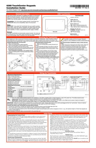
  • 1. 6280 TouchCenter Keypads Ê800-07600ÀpŠ Installation Guide 800-07600 7/11 Rev. A For Online Support visit: http://www.security.honeywell.com/hsc/resources/MyWebTech/ General Information 6280 TouchCenter This guide provides information on installing and setting up Honeywell's Front Panel LEDs 6280 TouchCenter Keypads. The 6280 Series graphical touch-screen SD/SDHC CARD Slot keypads are Advanced User Interface (AUI) devices, which combine control of your security system, multi-media and premises lighting. ARMED (RED) LED ON – System is armed. Compatibility: For a list of alarm systems that the TouchCenter can OFF – System is not armed. interface with, refer to the Compatibility Table in this document. READY (GREEN) LED Wiring ON – System is disarmed and ready to arm. IMPORTANT: If you power the TouchCenter from your panel’s auxiliary OFF – System is armed or disarmed but not power output, check your panel’s Installation and Setup Guide and verify ready. If disarmed, faults or troubles are present. that this device and others do not exceed your panel’s auxiliary power MESSAGE (YELLOW) LED output capability; if it does, a supplementary power supply is needed. FLASHING – The system contains new message(s) for the User. Word List OFF – No new messages. The 6280 TouchCenter can annunciate a series of words. You must use the vocabulary list in your alarm panel instructions for actual words that RESET BUTTON Press to unlock keypad 6280-001-V0 may be annunciated; refer to the Word List in this document. Mounting the TouchCenter This Keypad is for indoor use only and should be mounted at a comfortable viewing level. Avoid mounting in areas of The 6280 complies with the European Standard high condensation such as bathrooms or in locations where bright light or sunlight shines directly on the screen. The EN50131 and is designed to prevent unauthorized use. TouchCenter can be mounted with or without the mounting plate. Use the center securing screw for European installation. Standard Mounting with mounting plate: Mounting without mounting plate: Mounting (European Installations) using a center securing 1. Select a mounting location. 1. Select a mounting location. screw: 2. Detach the mounting plate by sliding downward. 2. Detach the mounting plate by sliding downward and 1. Detach case front by removing the two bottom screws. Gently pull 3. Use the mounting plate to mark the location of the mounting discard. up using a screwdriver if necessary and pry apart. Lift off cover. holes on the mounting surface and check for level. 3. Use the template (provided in the carton) to mark the 2. Mount the TouchCenter in its final location, (see “Standard 4. Locate the mounting plate over the mounting surface such that location of the mounting screws and the cut-out for the Mounting” or “Mounting without the mounting plate”) install center the wire/cable access openings are aligned while passing the TouchCenter assembly on the mounting location. Check securing screw (supplied) and tighten to mounting surface. wires/cable through the case back. for level. 3. Replace the case front and secure using the two bottom screws. ***Go to “Wiring the TouchCenter” and complete wiring*** 4. Install 4 screws (supplied) in the mounting surface 5. Secure the mounting plate to mounting surface using 4 screws leaving screw heads 1/8” above the mounting surface. (supplied). 5. Locate the case back over the mounting surface such 6. Slide TouchCenter onto mounting plate. that the opening is aligned with the wire/cable access WALL SURFACE opening on the mounting surface while passing the CASE INSTALL TAMPER MOUNTING FRONT SCREW SCREWS (4) (TYP) wires/cable through the opening in the case back. **Go to “Wiring the TouchCenter” and complete wiring 6. Mount TouchCenter by sliding onto the screw heads. WALL SURFACE 6280 SE RIE SC AS TEMPLATE EB AC K CASE 4- 3/4 " MO UN TIN BACK GT EM PL DETACH CASE FRONT AT E BY REMOVING SCREWS (2) AND LIFT UP CU 6280-015-V0 T-O UT LO CA TIO N DR ILL 3/1 6" WALL 4 PL DIA AC . HO ES LE S MOUNTING Ê8 00 0883 -0 800- DR ILL PLATE MOUNTING 1 08 3/1 6" 3 - 9/16" 5/11 31 DIA Rev .A uŠ . HO 6280-016-V0 LE (OPTIONAL) SCREWS INSTALLED 1/8” ABOVE SURFACE 6280-006-V0 Wiring the TouchCenter Mechanical Specifications: Width: 8 inches (203.2mm) CONTROL POWER FROM SUPPLEMENTARY Height: 5-1/2 inches (139.7mm) TERMINAL STRIP POWER SUPPLY IF USED Depth:1-3/8 inches (35mm) 6280 AUX AUX DATA DATA SUPPLEMENTARY CONTROL IN OUT +12 VDC TERMINAL STRIP Electrical Specifications: POWER SUPPLY YELLOW P/N AD12612 AUX AUX DATA DATA Backlight OFF, Sound OFF 12V, 140mA (DATA FROM IN OUT Backlight ON, Sound OFF 12V, 205mA CONTROL) Backlight ON, Sound ON 12V, 270mA Y RED (+12VDC) Operating Environment: BLACK (GND) Humidity 93% RH, no condensation BLACK BLACK G GREEN (DATA TO RED Temperature: CONTROL) GREEN Operating 14˚ F to 131˚ F / -10˚ C to 55˚ C YELLOW Shipping / Storage -40˚ F to 158˚ F / -40˚C to 70˚C Wire Gauge: Length #22 gauge 150 feet #20 gauge 240 feet 6280-014-V0 #18 gauge 350 feet #16 gauge 550 feet Use a UL Listed, battery-backed supply for UL installations. The battery supplies power to these keypads in case of AC power loss. The battery-backed power UL supply should have enough power to supply the keypads with the UL required minimum standby power time. IMPORTANT: Keypads powered from supplies that do not have a backup battery do not function if AC power is lost. Make sure to power at least one keypad in each partition from the control’s auxiliary power output or UL Listed battery backed up power supply. IMPORTANT: When the TouchCenter is powered from an auxiliary power supply, always apply power to the control panel first and then the TouchCenter. Failure to observe this sequence results in improper operation of the TouchCenter and may result in an ECP Error indication. Connect the wires to the TouchCenter terminal block as shown. • Connect the TouchCenter in parallel with keypads and other peripheral devices using the keypad data (ECP) bus. • If the TouchCenter is used as the primary system keypad, maximum wire run length is 150 feet. • If more than one keypad is wired to one run, then the maximum lengths must be divided by the number of keypads on the run. (e.g., the maximum length is 75 feet if two keypads are wired on a #22 gauge run). Note: Unshielded 4-conductor cable is recommended for the power/data wire. Initial Setup Programming the Control Panel completion. If there are to be additional TouchCenter units in the system, after The TouchCenter is not fully operational unless its address in the control panel enabling addresses in the control panel using an alpha-keypad, power-up each has been enabled (set as an alpha console) AUI type device, and assigned to a TouchCenter one at a time, and set its address to one of the addresses you partition (where applicable). enabled in the control panel. We recommend that you use either a standard alpha keypad or the TouchCenter in Note: If the top of the screen is displaying ECP Error, the TouchCenter ECP Console Emulation Mode when programming the control panel. When in the Address is not valid for the panel that it is connected to. To change the ECP Console Mode, the TouchCenter emulates an alpha keypad and the programming Address, enter the default code of “4140” to advance to the next screen. of the panel is performed following the procedures provided in your panel’s Note: 4140 is the TouchCenter default installer code before connecting to a Installation & Setup Guide. control panel. Once connected to a control panel, use the panel’s installer code. Note: When programming your control panel, if you change the zone types for your Change the ECP Address on the unit, using the Up/Down arrows and then touch emergency zones you may disable the emergency icons in the TouchCenter. The apply to accept the address and reset the TouchCenter. Once communication has emergency icons in the TouchCenter are active for zone types 06 and 07 (Panic been restored, then use the standard panel installer code for all installer icon), 08 (Medical icon), and 09 (Fire icon). Additionally, the Medical icon is also functions. Refer to “ECP Setup” section. compatible with a zone type 15 (24-Hour Medical) for panels that contain this zone Time/Date Setup type. If not already set from the panel, set the current time and date. Refer to The TouchCenter should not be assigned as a Master Console. If the TouchCenter “Time/Date Setup” section. is assigned as a Master Console, partitions must be controlled from the Partition NIGHT Setup screen or by using the Console Emulation Mode. The TouchCenter is defaulted to arm the system in the STAY INSTANT mode TouchCenter Initialization when arming the system using the NIGHT icon. When initially powered, the screen displays the boot sequence and the "Set ECP Select the arming mode to be activated when the NIGHT icon is touched on the Address" screen is displayed. If the system is incorporating only one TouchCenter, "Arming" screen, refer to “Night Setup” section. leave the address set to 1 and touch Apply. The boot-up process continues until * Refer to the instructions on the following pages to customize your TouchCenter.
  • 2. HOME SETUP DISPLAY & AUDIO SYSTEM SETUP MULTI-MEDIA Ready To Arm Ready To Arm Ready To Arm Ready To Arm Ready To Arm Backlight Off To Homepage Auto Slideshow After After After 5 Min 30 sec 5 Min CS Setup Wed 01/19/2000 System Info System Video Message Security Light Setup Operating Modes 16:07HRS Time/Date User Chime Mode Voice Mode Voice Chime Setup Setup CLEAN MultiMedia P1 H Disp & Audio Setup SCREEN P1 H Advanced Setup Picture 0 8 : 5 7 P M Tu e 0 1 / 11 / 2 0 0 0 0 1 : 0 0 A M We d 0 1 / 0 1 / 2 0 0 3 Adjust the Brightness / Volume Notes Navigation Icons 1. Touch the Setup icon located in the lower If changes are made, when you exit a ICON ICON TITLE FUNCTION left corner of the “Home” screen. Settings Changed! Pop-up window is 2. Move the Brightness/Volume slide bar to displayed asking “Remember New Settings?“ Accesses the Product Introduction Yes saves the change. “Intro Video” adjust the brightness/volume. Video. No discards the change. Chime Mode, Voice Mode, Voice Chime Notes Record and retrieve Voice From the “Setup” screen; If the Chime Mode and Voice Mode are both “Message” Messages. 1. Touch the Disp&Audio Setup icon. selected, the Voice Chime is automatically 2. Enter your “Authorized Code" if required. selected. Turn certain devices on and off (if It may take a few seconds for the Chime 3. Select Chime Mode or Voice Mode to "Light” installed and programmed by your Mode to take effect. turn the mode on or off. installer.) When the TouchCenter exits the “Operating Modes” screen, your selection is saved. "Security” Accesses "Security" screen. Adjust the Screen Timeouts Notes From the “Setup” screen; If changes are made, when you exit a 1. Touch the Disp&Audio Setup icon. Settings Changed! pop-up window is “Home” Returns you to the "Home" screen. displayed asking “Remember New 2. Enter your “Authorized Code" if required. Settings?“ 3. Touch the desired selection from the drop- Settings include: down list displaying the time period for each “Back” Reverts to the last screen viewed. • Backlight Off After X time option. • Return To Homepage After X time Yes saves the change. • Auto Slideshow After X time. Displays Emergency functions (as No discards the change. programmed by the installer). See Clean Screen Notes Programming the Control Panel note. “Panic” Note: This icon is displayed and 1. From the “Home” screen, touch the At the "Touch Screen Disabled for =30 active on all screens except while in Seconds" screen, the touch screen should be Setup icon. the Clean Screen mode and during wiped clean of fingerprints using a mild soap 2. Touch the Disp&Audio Setup icon. solution and a soft cloth. When the counter an LCD Display test in Diagnostics. 3. Enter your “Authorized Code" if required. reaches zero, the window automatically closes 4. Touch the CLEAN SCREEN icon to disable and the touch screen is active. “Control Panel This icon alerts the user to a Control Message” Panel Message. the TouchCenter for 30 seconds so you can IMPORTANT: Do not use an abrasive wipe the screen clean. cleaning agent or abrasive cloth when A pop-up window displays "Touch Screen has cleaning the TouchCenter or damage to the Accesses the Message, Picture and been disabled so that you may wipe the screen touch screen may occur. “Multi-Media” Video feature. clean. Please use a damp, soft cloth. DO NOT NOTE: The Emergency screen cannot be use any liquids, sprays, or ammonia-based accessed while running in the clean screen cleaners. Press CONTINUE to disable mode. “Setup” Allows access to Setup menus. touchscreen." ** Panics cannot be initiated during this process** Touch Cancel to exit. Multi-Media: Video Setup Notes 1. Insert your personal media (SD/SDHC) NOTE: The VLC Video Converter is required “Voice Status” Allows user to hear system status. card first. to convert videos for proper playback on the 2. Touch the Multi-Media icon, and then 6280. Use an Internet search engine to locate and download the VLC touch the Video icon. “Video” Allows user to play video files. Player/Converter, then follow the steps in the 3. Highlight a video file from the list and “VLC Video Converter Instructions” guide touch Play to start the selected video file. (provided in the carton). • Use the slide bar to scroll through the Allows user to display personal “Picture” photos in a slide show format. video list. NOTE: Maximum video resolution should not • If desired, touch the Full View icon to exceed 400 x 240. view video in full screen. Video files can be viewed from an “Minimize Minimizes the Home screen icons (SD/SDHC) Card. Home” when viewing wallpaper displays. Video Icons Play Pause Full View Repeat Users can touch the appropriate icon to Play, “Maximize Maximizes the Home screen icons Pause, view a Full View or Repeat the video. Home” when viewing wallpaper displays. NOTE: If the video file causes the keypad to lock, press the reset button on the bottom of the keypad to reset the keypad. Panel Default Displays Picture Setup The “Security” screen displays an Icon(s) if a panel fault occurs. Notes The following lists the Icons that are displayed to the left of the 1. Insert your personal media (SD/SDHC) The Picture feature allows you to set up and Panic icon. card first. view photos as a slide show or as your ICON MEANING 2. Touch the Multi-Media icon, and then wallpaper display. Photo files can be viewed from the (SD/SDHC) Card. Formats AC Loss; touch the Picture icon. supported are .bmp or .jpg files. The system is not receiving AC power. 3. Select the type of viewing transition NOTE: Bell Failure; desired by touching the Transition arrow. • To exit the Picture feature at any time The system bell or siren has a problem. Note: This Icon Select from (Standard, Horizontal, Vertical and resume keypad operation, touch is displayed when interfacing with residential panels only. or Fade Out). anywhere on the screen. 4. Touch the Slide Delay arrow to select the • The first image is displayed and a list of Expander Failure; time interval (5, 10, 15, or 20 seconds) that The system has a failure in an expansion module. stored images appears on the screen. you want to allow for each photo being • When an image is loading, no other Low Battery; viewed. Picture Setup functions can be performed The system battery, that powers the system during an AC To set a picture as wallpaper: (play, previous, next, add or set power loss, is low. 1. Use the slide bar to scroll through the list wallpaper). LRR Supervision Failure; Touch the TOP button to move up one level of pictures and highlight the file you want to in the directory. The Communication Device used to communicate with be displayed on the keypad screen. the central station has a supervision failure. Touch the OPEN button to view larger 2. Touch the Set Wallpaper icon; view your images and/or open directories, select from Max Attempts Exceeded; selection from the “Home” screen. the list of stored images. The system has exceeded the maximum attempts to NOTE: When viewing wallpaper displays, the Home Touch the CLEAR ALL button to clear all communicate with the Central Station. screen icons can be minimized by touching the pictures from the current slide show rotation. “Minimize Home” icon. Touch the “Maximize Home” Touch the Picture icon (on the Home screen) Pager Failure; icon to maximize Home screen icons. to go into the Slide Show feature. The system cannot communicate with an assigned pager. Picture Icons Telco-1 Cut; The system is not able to communicate with the central monitoring station over the primary phone line. Telco-2 Cut; The system is not able to communicate with the central Play Image Previous Image Next Image Add Image Minimize Home Maximize Home monitoring station over the secondary phone line. Wireless Failure; The system is not able to communicate with its wireless devices. -2-
  • 3. CS Setup Notes COMPATIBILITY TABLE Maximum Number Minimum Software 1. From the System Setup screen, touch the When the TouchCenter cannot communicate of TouchCenters Revision Level with the alarm panel, the message “ECP Alarm System CS Setup icon. Error” is displayed, check the following: VISTA-15P 2 3.0 •Verify that the AUI type device is enabled in VISTA-20P 2 3.0 2. Enter your “Authorized Code", if required. the control panel, and that the ECP address VISTA-20P 4 5.0 3. Touch the ECP Address icon. in the TouchCenter matches the address VISTA-21IP 4 1.0 enabled in the control panel. Use a different address for each device. VISTA-128BP 3 3.2 • If powering the TouchCenter from a power VISTA-128FBP 3 1.6 supply, make sure you have a common VISTA-128FBP-9 3 4.1 ECP Address ground installed (wiring between Power VISTA-250FBP-9 3 4.1 1 1. Touch the ECP Address icon. Supply "gnd" and panel "Aux. power neg"). VISTA-250BP 3 2.4 On residential control panels (VISTA-20P 2 2. Select the ECP address for this or equivalent), up to four TouchCenters VISTA-250FBP 1 1.5 TouchCenter using the Up/Dn arrows. may be used. Addresses 1 and 2 (in field VISTA-250FBP 3 2.0 3 3. The available ECP addresses are: *189) are enabled by default. If the defaults VISTA-128BPE 3 4.4 1-2, 5-6 for residential controls have been changed, enable these VISTA-250BPE 3 4.4 addresses (in field *189) using an alpha- VISTA-128BPEN 3 7.0 1-2, 3-30 for commercial controls under keypad and the Data Field Programming VISTA-128BPLT 3 6.0 Rev. 10 supports 3 AUIs. See procedures located in the panel Installation and Setup Guide. VISTA-128FBPN 3 5.1 Important Note below. VISTA-128BPT 6 10 On commercial control panels (VISTA- 1-30 for commercial controls Rev. 10 128BP, VISTA-128FBP or equivalent), VISTA-250BPT 6 10 and higher supports 6 AUIs. These addresses in the control panel are VISTA-128BPTSIA 6 10 IMPORTANT: If multiple TouchCenters are being normally not defaulted for AUI type devices. To enable the addresses you are using for FA148CP 2 3.0 used, they must be set to addresses 1, 2, and X (where X equals any address from 3 through 30). TouchCenters, use an alpha-keypad and FA168CPS 4 5.0 Only one AUI type device may be assigned to an follow the procedures for “Device FA1660C 3 3 address from 3 through 30 on commercial control Programming” in your control panel FA1660CT 6 10.1 panels. “Programming Guide.” FA1670C-9 3 4.1 The TouchCenter should not be assigned as a NOTE: When the ECP address is FA1700C 3 3 Master Console. If the TouchCenter is assigned as a changed, and Apply is selected, the Master Console, partitions must be controlled from TouchCenter resets. the Partition screen or using the Console Emulation Mode. Apply accepts the address setting. Lighting/EN50131 Display Notes When the EN50131 Display feature is turned ON: 1. From the System Setup screen, touch the The EN50131 Display compliance feature •The keypad returns to the "Home" screen after 30 seconds and the "Armed" and "Ready" LEDs turn OFF. CS Setup icon. is a European Standard designed to prevent unauthorized users from knowing •The "To Homepage After" time setting changes to 30 seconds and 2. Enter your “Authorized Code", if required. the time is non-selectable. the status of the Security System. 3. Touch the Options icon. •The Security, Message and Lighting screen does not display 4. Select "Lighting" or "EN50131 Display" to system status until an authorized user code is entered. Note: DO NOT select the Demo Mode turn the option on or off. option. This option should only be • The "Setup" menu does not display system status until an 5. Select "Normal Mode" or "Safe Mode" to selected if instructed to do so by factory authorized user code is entered. turn the option on or off. service. When this option is selected, the Apply accepts all changes. keypad does not communicate with the Operating Modes control panel and any user can select Automatic Entry- In the rare event that the TouchCenter cannot Advanced Setup screens. successfully communicate in its graphic mode with the control panel, the TouchCenter displays “Problems detected. Start Keypad in Safe Mode?” and requests a “Yes” or “No” response. If you Safe Mode Notes answer with “Yes”, the TouchCenter enters into the Safe Mode. If you answer with “No”, the TouchCenter tries to communicate with 1. Select Safe Mode and then touch Apply. The Safe Mode may be automatically the panel again. After 3 consecutive times of receiving no response, entered by the TouchCenter program on a ! SAFE MODE ! 2. Touch the OK icon. communication failure or may be entered the TouchCenter enters the Safe Mode automatically. 3. To exit, touch the safe mode bar and touch manually on command. Manual Entry - Note: ONLY enter the Safe Mode from the Yes to return to Normal Mode. Normal Mode. Entering the Safe Mode from the Demo Mode may While in the Safe Mode, the Home screen The TouchCenter resets and restarts in the result in incorrect display of the Emergency Function keys. displays the Security, Panic, and Message Safe Mode. Icon. A message !SAFE MODE! is be displayed at the bottom of the screen. Operating in the Safe Mode This is a limited mode of operation. While in this mode: Screen Security Notes • You can use the Security icon to access the Console 1. From the System Setup screen, touch the Note: The Screen Security screen Emulation Mode of operation to try to clear your faults, CS Setup icon. contains a heading of Advanced Setup, disarm the system, or enter additional Alpha Keypad 2. Enter your “Authorized Code", if required. Central Station Setup, Disp. & Audio commands specified in your panel User and Installation Setup, Event Logs, Lighting, Message, Guides. You can perform almost all functions that you can Security, and Time/Date. perform from a standard non-graphic alpha keypad. 3. Touch the Screen Security icon. The Screen Security screen is re- • You can touch the “Panic” icon and generate Emergency 4. If authority levels are correct, touch Back displayed listing any changes. Messages as defined in the panel's home partition for this or Home to exit menu. Note: The User Levels listed on this TouchCenter. 5. If changes are necessary, select the line to screen match the User Levels in • The Armed and Ready LEDs on the front of the TouchCenter be changed and the level of user to have commercial panels. See the chart below indicate the TouchCenter’s home partition status. access, then select the OK icon. for corresponding User Levels in • The Chime mode functions in the Safe Mode: however, there Residential Panels. is no Voice, Voice Chime, or Message capability. Code Authority Notes WARNING: The Slide Show feature does not start automatically in Safe Mode. 1. Touch the Code Authority icon. The Code Authority icon displays User User Code Setup 2. Enter the 4-digit User Code for the user Names and Partition Authority Level for Each user must be assigned a name with a corresponding 4-digit that you want to obtain Authority Level the User Code. user code in order to gain access to various features and functions. information about. The TouchCenter can hold the identity for 10 Users in its memory. 3. Touch the BACK icon. If additional Users are needed, define the additional Users using Device Events Notes the Console Emulation Mode. Users for the system are programmed in a central user setup 1. Touch the Device Events icon. The control panel must be programmed to location that provides the specific questions for authorization record various system events in installer levels assigned to different users. You may want these users to be 2. To view a record of events in a history log, programming mode. the same, but there are situations in which you may want a user touch the up/down arrow to scroll. to have limited capabilities. Panel Configuration Notes User Related Note • Users added to the system using the TouchCenter graphic user 1. Touch the Panel Config icon. A "Panel Configuration" screen is screen must be deleted from the TouchCenter using the graphic displayed providing details of your system. If you select OK, the TouchCenter resets and screen as well. Deleting users from the panel by any other Delete clears the configuration from the the panel configuration is downloaded from means (alpha keypad, console emulation mode, or Compass TouchCenter and reloads the panel the panel into the TouchCenter. downloader) does not automatically delete them from the configuration into the TouchCenter. TouchCenter. Add/Delete/Edit a User Notes • If the panel has exit tones enabled and you arm the system in the 1. From the System Setup screen, touch the Note: The authorized code for adding, Away mode, the TouchCenter beeps continuously throughout the deleting and editing users is dependent exit period. User Setup icon. upon the alarm panel you are connected • Use the console emulation mode for the following functions: 2. Touch the ADD User icon and enter your - Programming more than 10 system users. to. Check your alarm panel Installation “Authorized Code”. and Setup Guide to determine who can - Programming the Pager report option for users of residential 3. Touch the box next to Enter User Name; add users. control panels (e.g., VISTA-15P and VISTA-20P). enter user name. Type in the user name (6 characters max.; - Special Function Key operations (macros or single-button 4. Touch the OK icon. no spaces between characters) paging). 5. Touch the box next to User Number; enter Notes: - End-User Scheduling. • Use the Shift key for capital letters. User Number for this user. - To check for an “Alarm Cancelled” message if this feature has • Use the BS (Backspace) key to make 6. Touch the box next to Enter User Code; corrections. been enabled in the system. enter the User Code for this user. The @#$ key is not available for use at 7. Touch the box next to RF Button Zone; this time. enter the 3-digit RF Button Zone for this If assigning this user to a wireless key, user. enter one of the zone numbers of the keyfob (the wireless key must be 8. Touch Save. programmed before it can be assigned to Follow this procedure for deleting and a user). editing users. NOTE: To edit a User ‘name’ or ‘number’, you must delete the User and re-enter. -3-