SlideShare une entreprise Scribd logo
1  sur  27
Télécharger pour lire hors ligne
1
New materials for capacitor design
Term paper by
Aritra Majumder
2
1. Introduction
Keywords: ceramics, ionic compounds, polarization, dielectric constant, linear
dielectrics, non-linear dielectrics, electro ceramics, dissipation factor, electronic
relaxation, perovskite structures, ferro electric, piezo electric. δ = loss angle (greek letter
delta), DF = dissipation factor, Q = quality factor, ESR = equivalent series resistance,
Xc = reactance of the capacitor in ohms.
Dielectrics are charge bearing electrical insulating materials. In fact all insulators are
dielectric, although the capacity to support charge varies greatly between different
insulators for reasons that will be examined in this presentation. These materials bear
charge without conducting by a significant degree. These are basically insulating or non-
conducting materials.
Most ceramic materials in nature are dielectric and are used in many applications such as
capacitors (ceramic capacitors), memory elements (DRAM), sensors (Industrial Gas
Sensors) and actuators (solid state actuators). There are various categories of Dielectrics
namely low  dielectric materials & high dielectric materials.  is the measure of
Dielectric Constant of a dielectric.  will be elaborated in a simple intuitive manner, it
can be said that k is a quantitative measure of the extent to which a material concentrates
electric flux lines, and it is the electrical equivalent of relative magnetic permeability. To
judge and quantitatively analyze any dielectric materials we need to see four parameters
namely 1. Dielectric constant (), 2. Dielectric Strength, 3. Dissipation Factor (tanand
4. Electrical resistivity (). Controlling the bulk synthesis parameters of ceramic
insulators we can improve or change the dielectric properties of the ceramic dielectric.
Non-destructive characterization of dielectric materials is hence important to document
the relationships between the interplaying factors.
When we talk/discuss about dielectric property of matter how can we not describe the
magnetic property of matter? For ceramic materials dielectric and magnetic
characteristics of are of great importance as the field of solid-state electronics continues
3
to expand. This field is one in which limitations of available materials are frequently the
bottleneck preventing improved designs. Also, the reliability of components is of great
importance for many applications; the failure of one component can cause failure of an
entire missile costing several millions of dollars, for example. At the same time there is
an extensive effort to reduce the size of all communications devices. All these factors
have led to an increasing interest in ceramic insulators and semiconductors.
2. Literature Review
2.1 Capacitor a passive electrical device that stores charge in a dielectric medium placed
between two conducting surfaces commonly known as condenser.
2.2 Capacitance is the electrical property of a capacitor that gives the measure of the
capacity of the capacitors to store electrical charge onto its two plates with the unit of
capacitance being the Farad (abbreviated to F) named after the British physicist Michael
Faraday.
C=Q/V (In terms of Charge stored and Potential Difference) [1]
C=0A/d (In terms of Dielectric constant and dimension) [2]
Figure no-1 Figure no-2
4
Capacitance of One Farad is defined when a charge of One Coulomb is stored on the
plates by a voltage difference of One volt between the two plates. Capacitance, C is
always positive in value and never has a negative value. One Farad is a very large unit of
measurement to use on its own so sub-multiples of the Farad are generally used such as
micro-farads, Nano-farads and Pico-farads.
Variety of units is used for dielectric properties and these are sometimes confusing. Three
basic sets of units are used. In the electrostatic-units system (esu), electrical energy is
related to mechanical and thermal energy in the cgs system by Coulomb's law for the
force exerted between electric charges. The dielectric constant is arbitrarily taken as a
plain number. In electromagnetic units (emu) the permeability is taken as a plain number.
These formulations lead to some inconsistencies and fractional expressions in
dimensional equations; these can be eliminated by taking the electrical charge as a fourth-
dimensional unit. This is done in a rationalized system in which for practical units the
meter (m), kilogram (kg), second (sec), and coulomb (c) are used as primary units. This is
called the mks system. Several derived units such as amperes and ohms are used for
convenience. In this system the dielectric constant of free space becomes o = (36π)-1
X
10-9
= 8.854 X 10⁻¹²
F/m.
Figure no-3 Figure no-4
5
The above model of a capacitor was an Ideal one, now let’s look at the practical
model of capacitor. A practical capacitor is also known as a Lossy dielectric
capacitor.
2.3 Lossy Dielectrics
Capacitors are used for a wide variety of purposes and are made of many different
materials in many different styles. For purposes of discussion we will consider three
broad types, that is, capacitors made for ac, dc, and pulse applications. The ac case is the
most general since ac capacitors will work (or at least survive) in dc and pulse
applications, where the reverse may not be true. It is important to consider the losses in ac
capacitors. All dielectrics (except vacuum) have two types of losses. One is a conduction
loss, representing the flow of actual charge through the dielectric. The other is a dielectric
loss due to movement or rotation of the atoms or molecules in an alternating electric
field. Dielectric losses in water are the reason for food and drink getting hot in a
microwave oven.
One way of describing dielectric losses is to consider the permittivity as a complex
number, defined as
{1}
Where,
= ac capacity
= dielectric loss factor
δ = dielectric loss angle
Capacitance is a complex number C∗ in this definition, becoming the expected real
number C as the losses go to zero. That is, we define
{2}
One reason for defining a complex capacitance is that we can use the complex value in
any equation derived for a real capacitance in a sinusoidal application, and get the correct
phase shifts and power losses by applying the usual rules of circuit theory. This means
6
that most of our analyses are already done, and we do not need to start over just because
we now have a lossy capacitor.
Equation {1} expresses the complex permittivity in two ways, as real and imaginary or as
magnitude and phase.
The magnitude and phase notation is rarely used. Instead, people usually express the
complex permittivity by and tan δ, where
{3}
Where tan δ is called either the loss tangent or the dissipation factor DF.
The real part of the permittivity is defined as
{4}
Where is the dielectric constant and is the permittivity of free space.
Dielectric properties of several different materials are given in Table 1. Some of these
materials are used for capacitors, while others may be present in oscillators or other
devices where dielectric losses may affect circuit performance. The dielectric constant
and the dissipation factor are given at two frequencies, 60 Hz and 1 MHz The right-hand
column of Table 1 gives the approximate breakdown voltage of the material in V/mil,
where 1 mil = 0.001 inch. This would be for thin layers where voids and impurities in the
dielectrics are not a factor. Breakdown usually destroys a capacitor, so capacitors must be
designed with a substantial safety factor. It can be seen that most materials have dielectric
constants between one and ten. One exception is barium titanate with a dielectric constant
greater than 1000. It also has relatively high losses which keep it from being more widely
used than it is. We see that polyethylene, polypropylene, and polystyrene all have small
dissipation factors. They also have other desirable properties and are widely used for
capacitors. For high power, high voltage, and high frequency applications, such as an
antenna capacitor in an AM broadcast station, the ruby mica seems to be the best.
Each of the materials in Table 1 has its own advantages and disadvantages when used in a
capacitor. The ideal dielectric would have a high dielectric constant, like barium titanate,
a low dissipation factor, like polystyrene, a high breakdown voltage, like Mylar
(Polyethylene terephthalate), a low cost, like aluminum oxide, and be easily fabricated
7
into capacitors. It would also be perfectly stable, so the capacitance would not vary with
temperature or voltage. No such dielectric has been discovered so we must apply
engineering judgment in each situation, and select the capacitor type that will meet all the
requirements and at least cost.
Capacitors used for ac must be un-polarized so they can handle full voltage reversals.
They also need to have a lower dissipation factor than capacitors used as dc filter
capacitors, for example. One important application of ac capacitors is in tuning electronic
equipment. These capacitors must have high stability with time and temperature, so the
tuned frequency does not drift beyond some specified amount.
Another category of ac capacitor is the motor run or power factor correcting capacitor.
These are used on motors and other devices operating at 60 Hz and at voltages up to 480
V or more. They are usually much larger than capacitors used for tuning electronic
circuits, and are not sold by electronics supply houses. The term power factor PF may
also be defined for ac capacitors. It is given by the expression
PF = Cosθ {5}
Where θ is the angle between the current flowing through the capacitor and the voltage
across it.
The capacitive reactance for the sinusoidal case can be defined as
XC =1/ωC {6}
Where ω = 2πf rad/sec, and f is in Hz.
In a lossless capacitor, = = 0, and the current leads the voltage by exactly 90o. If is
greater than zero, then the current has a component in phase with the voltage.
{7}
For a good dielectric , so
{8}
8
Therefore, the term power factor is often used interchangeably with the terms loss tangent
or dissipation factor, even though they are only approximately equal to each other.
We can define the apparent power flow into a parallel plate capacitor as
{9}
By analogy, the apparent power flow into any arbitrary capacitor is
{10}
The power dissipated in the capacitor is
{11}
2.4 Maxwell’s Equations
To study and understand dielectrics we need to briefly be acquainted with the cardinal
laws of electro-magnetism. The four basics rules are known as Maxwell’s equation.
Maxwell’s equations are used to understand and explain the dielectric properties of
materials. Four differential equations were proposed by James Clerk Maxwell in 1864
that form the basis of the theory of electromagnetic waves. The written, in vector notation
(Integral-Differential form), are as follows:
1. Also known as Gauss’s Law
{12}
The electric flux leaving a volume is proportional to the charge inside.
2. Also known as Gauss’s Law of magnetism
{13}
There are no magnetic monopoles, total magnetic flux through a closed surface is zero.
9
3. Maxwell–Faraday equation (Faraday's law of induction
{14}
The voltage induced in a closed loop is proportional to the rate of change of the magnetic
flux that the loop encloses.
4. Also known as Ampère's circuital law
{15}
The magnetic field induced around a closed loop is proportional to the electric current
plus displacement current (rate of change of electric field) that the loop encloses.
Note: B is the magnetic flux density, E the electric field strength or intensity, H the
magnetic field strength or intensity, ρ the charge density, and J the current density. Q is
charge enclosed, o is the permittivity of free space, µo is the permeability of free space, ɸ
is the flux vector and Nabla is the vector differential operator also known as Del.
The basis of electromagnetic theory was expressed in the above formulas by James Clerk
Maxwell who hypothesized from mathematical considerations, that light was a formation
of electromagnetic waves. Heinrich Hertz in 1887-1891, discovered that electromagnetic
waves travel at a finite velocity. The application of ceramics for electrical devices was
developed in 1887, when Lord Rayleigh (John William Strutt), showed that an infinitely
long cylinder of dielectric material can act as a guide for electromagnetic waves.
2.5 Polarization
To understand polarization we have to know what the source/origin of polarization is.
Let’s look into it. Origin of Polarization
At zero field, the centers of positive and negative charges coincide. Upon application of a
dc or static electric field, there is short range migration of charges. However, there is a
limited movement of charges leading to the formation of charge dipoles and the material,
10
in this state, is considered as ‘polarized’. These dipoles are aligned in the direction of the
applied field.
The applied field can also align the dipoles that were already present in the material i.e.
material containing dipoles without application of the field are called Polar materials.
Of course, both these effects may be present in single material i.e. dipoles can be aligned
as well as be induced by the applied field. Net effect is called as ‘Polarization’ of the
material.
Dipole Moment (C.m) 𝜇 = 𝑞.𝑑 {16}
Polarization (C/m2)
(Dipole moment per unit volume) 𝑃 = {Σ𝜇}/ 𝑉 {17}
So, if all the dipoles were aligned in a direction, then P=N.μ {18}
Conversely, if all the dipoles were aligned in random directions,
Then, P=N.Σμ=0 {19}
2.6 Types of Polarization
The different Polarization mechanisms are as follows and their frequency dependence
• electronic polarization
• ionic polarization
• molecular polarization
2.6.1 Electronic Polarization (e) as in Elemental solids
Figure no-5
11
2.6.2Ionic Polarization (i) as in Ionic solids
2.6.3Orientation Polarization (o)
Figure no-6
Figure no-7
Figure no-9
Figure no-8
Figure no-10 Figure no-11
12
2.7 Ceramics are inorganic and non-metallic materials that are commonly electrical and
thermal insulators, mechanically brittle and chemically composed of more than one
element. Ceramics mostly have ionic bonds (and also some amount of covalent bonds) of
atoms which is as strong as the metallic bonds. Ionic bonds are created between two
atoms one metallic and one non-metallic with hugely different electro-negativities.
The engineering ceramics are typically classified into the following groups:
(i) Ionic Ceramics like ZrO2, MgO and Al2O3.
(ii) Covalent Ceramics like SiC.
(iii) Amorphous ceramics based on Silica chains like Silicate Glasses.
Table 1
13
Ionic Ceramics (i)
have crystal structures that are either simple cubic, BCC or FCC along
with the interstitial holes filled up by the metallic ions.
Covalent Ceramics (ii)
are strongest among the ceramics. Typically the structure is very
much similar to Diamond having every second atom replaced by Silicon.
Amorphous ceramics (iii)
or Silicate Glasses are similar to Polymeric glasses, where the
silica chains form networks without any long range order.
Discovery of dielectric and magnetic behavior in ceramic and allied oxide materials.
Early navigators were familiar with magnetic behavior of ferromagnetic magnetite iron
(II, III) oxide (Fe3O4). The rough dielectric properties of BaTiO3 were discovered on
ceramic specimens independently by Wainer and Solomon in 1942, by Ogawa in 1944,
and by Wul in 1945. The first application of ceramics in the electrical production took
place because of its reliability when exposed to extremes of weather, as well as its high
electrical resistivity. The ferroelectric activity of BaTiO3 was reported independently by
Von Hippel in 1944, and by Wul in 1946.
With the discovery of barium titanate BaTiO3, the study of ferroelectrics increased
rapidly during the Second World War, after that, came a period of quick developments
with more than hundreds of ferroelectric identifications within the next decade, including
lead zirconate titanate, the most widely used piezoelectric transducer; about ten years
later, the concept of soft-modes and order parameter led to the period of “high science” in
the sixties. Neutron experiments verified the soft-mode concept and led to the detection
of several peculiar inappropriate ferroelectrics, such as gadolinium molybdate. In the
years seventy to seventy nine, there came the period of an increase in the variety of the
products in which electronic conduction phenomena in ferroelectric ceramics were
discovered.
Perovskite are a great group of crystalline ceramics, which obtained their name from a
specific mineral known as perovskite. The essential material perovskite was first
described in the year 1830, by the geologist Gustav Rose, who named it after the famous
Russian mineralogist Count Lev Alekseevich Perovski. Wainer, and Solomon, and their
collaborators found the ceramic perovskite dielectric in the 1940s. Around the year 1945,
14
R.B.Gray, was operating with piezoelectric ceramic transducers. He was one of the first
who had an obvious understanding of the significance of electrical poling in the setup of
a remnant polar domain arrangement in the ceramic, and consequently giving a strong
piezo response. It is perhaps difficult now to understand the absolutely innovative
thoughts which were required at that time to accept even the possibility of piezoelectric
response in an arbitrarily given polycrystalline, and it is perhaps not surprisingly that for
some time, disagreement rant and raved as to define whether the effect was electro
strictive or piezoelectric. The disagreement was successfully determined by Caspari and
Merz, in their demonstration of the pure piezoelectricity in untwined barium titanate
single crystals. In the earliest studies the ceramics used were largely BaTiO3, and poling
was carried out by cooling electrode samples, through the Curie temperature, around 120
C, under a substantial biased potential; the most favorable condition for individual
formulation being recognized by trial-and-error methods.
Jamilson Pinto Medeiros Elcio Correia de Souza Tavares Uilame Umbelino Gomes
and Wilson Acchar of Universidade Federal do Rio Grande do Norte determined
dielectric properties of sintered diatomite-titania ceramics were studied. The four most
important characterization properties , namely Specific capacitance, dissipation factor,
quality factor and dielectric constant were determined and they were plotted as a function
of sintering temperature, content of titania in them and frequency(frequency response);
the temperature coefficient of capacitance was measured as a function of frequency.
Besides leakage current, the dependence of the insulation resistance and the dielectric
strength on the applied dc voltage were studied. The results show that diatomite-titania
compositions can be used as an alternative dielectric.
2.8 Classification based on Crystal Classes
15
2.9 Symmetry Elements in Crystal systems
We have thirty two different classes. All those possible geometries will have 32 different
point groups. Within that all the kind of geometries are the geometrics configurations that
can be classified or grouped together. In crystallography we consider 32 crystal classes.
This 32 point group has been subdivisions of 4 basic crystal systems. So, there are and
then we have bravis lattices and so on. So, there are basically 7 crystal systems. We have
7 different crystal system and their quite familiar names to us these are triclinic,
monoclinic, orthorhombic, tetragonal, rhombohedral, hexagonal and cubic. Their
symmetries are different as in cubic is most symmetric whereas triclinic is the most non
Ferroelectrics
Piezoelectric
Pyroelectric
Dielectric Ceramics
Linear Dielectric Non-Linear Dielectric
Figure no-13
Figure no-12
16
symmetric. Now of the 32 point groups or crystal classes. 21 crystal classes do not
possess the center of symmetry.
Out of the 32 crystal classes 21 do not possess center of symmetry. A necessary condition
for the pyroelectricity to exist. And, 20 of these are actually piezoelectric. For
piezoelectricity to occur in a material the crystal or crystal structure must have certain
conditions and that is it must not have a center of symmetry.
Any crystal class or any crystal structure having center of symmetry will not be having
piezoelectric property. Out of 32 point groups or crystal classes 21 do not possess center
of symmetry. And, they are the materials or they are the crystals in which piezoelectricity
can be observed. One class although lacking a center of symmetry is not piezoelectric
because of other combined symmetry elements. Twenty crystal classes do not possess the
center of symmetry. And, all of them any material in this particular crystal structure or
crystal classes will have piezoelectric property. Well their effect may be small or big or
large, but in principal they have the piezoelectric property in them. So, there are large
number of impact as you can see out of 32, 20 have the piezoelectric property. So,
piezoelectric property is basically a common property in many minerals and crystals and
so on. Only 12 crystal classes do not have that, but other 20 of them have the
piezoelectric property. In principal many materials do have a piezoelectric property.
Crystal Classes (32)
Noncentro Symmetric (21)
Piezoelectric (20)
Pyroelectric (10)
Ferroelectric subgroup
Centro Symmetric (11)
Figure no-14
17
2.10 Linear Dielectrics
Let us take a look at the figure no-4 on the right hand side.
The Polarization versus Electric field graph is a y=mx, type of
Graph that passes through the origin and is a linear one.
Most dielectric materials become polarized when they are
placed in an external electric field. In many materials the
Polarization is proportional to the electric field.
(Figure no-4)
Where, is the total electric field (external + internal). The constant of proportionality,
is called the electric susceptibility. Materials in which the induced polarization is
proportional to the electric field are called linear dielectrics.
The electric displacement in a linear dielectric is also proportional to the total electric
field:
Where, ε is called the permittivity of the material which is equal to
Another phenomenon is of importance is dielectric breakdown. We observed that the
applied electric field causes small displacement of bound charges in a dielectric material
that results into polarization. Strong field can pull electrons completely out of the
molecules. These electrons being accelerated under influence of electric will collide with
molecular lattice structure causing damage or distortion of material. For very strong
fields, avalanche may also occur. The dielectric under such condition will become
conducting.
The maximum electric field intensity a dielectric can withstand without breakdown is
referred to as the dielectric strength of the material.
Figure no-15
18
Before proceeding to Non-Linear Dielectrics We must get familiar with a special
Oxide Structure of our Focus i.e. Perovskite
2.11 Perovskite
The family of compounds with general formula ABO3 is generally called perovskite
Oxides, as their structure is similar to the naturally obtained mineral CaTiO3.
The study on these compounds is important as they find several applications in non-linear
optics, memory devices, pyroelectric, piezoelectric sensors etc. apart from the academic
point of view due to the physical properties they exhibit. The well-known examples are
BaTiO3, PbZrO3, and PbTiO3 etc.
The structure is presented in Figure no-5.
The coordination number of A-site cation is 12 whereas the coordination number for the
B-site ion is 6. Initially, compounds with divalent ions in the A-site and tetravalent ions
in B-site were developed. Later on different valent ions were chosen to occupy A and B
sites. This structure is also called ‘simple’ perovskite.
The structure becomes ‘complex’ if two ions are of different valence and size in A as
well as B-sites.
This structure is called complex perovskite with the general formula (A’A”)(B’B’’)O3.
First attempt on the synthesis of complex perovskite was reported by Galasso and Pyle
(1963) and Galasso and Pinto (1965) with the modification in the B-site. The structures
that result when there exists perfect ordering in B-site with divalent and penta valent ions
in one set of compounds and trivalent and penta valent ions in other set of compounds are
given in Figure no-6. (A=Pb and Ba: B’=Mg, Zn, Y, Fe, Nd and Gd etc., and B’’= Nb
and Ta). Some of the well-known complex perovskite are Ba (Zn1/3Nb2/3)O3, (Onada
(1982) and Colla et al (1993)) Sr(Zn1/3Nb2/3)O3 (Onada (1982) and Colla et al (1993)),
(SrxLa1-x)MnO3 (Granado et al (1999)), etc. The nature of dielectric response of these
compounds find many applications such as Pb2+ based relaxor ferroelectric transducers,
actuators and multilayer capacitors and Ba2+ based dielectric resonator (DR) and
microwave band gap structure materials.
19
2.12 Non-Linear Dielectrics
The phenomenon of ferroelectricity was discovered in 1921 by J. Valasek who was
investigating the dielectric properties of Rochelle salt (NaKC4H4O6.4H2O). Barium
titanate (BaTiO3) was discovered to be ferroelectric in 1944 by A von Hippel and is
perhaps the most commonly thought of material when one thinks of ferroelectricity.
While there are many materials that exhibit ferroelectric properties, some of the more
common materials include: Lead titanate PbTiO3, Lead zirconate titanate (PZT), Lead
lanthanum zirconate titanate (PLZT).
Figure no-18
Figure no-16 Figure no-17
20
2.12.1 Pyroelectric Properties and Spontaneous Polarization all ferroelectric materials are
pyroelectric, however, not all pyroelectric materials are ferroelectric. Below a transition
temperature called the Curie temperature ferroelectric and pyroelectric materials are polar
and possess a spontaneous polarization or electric dipole moment. However, this polarity
can be reoriented or reversed fully or in part through the application of an electric field
with ferroelectric materials. Complete reversal of the spontaneous polarization is called
“switching”. The non-polar phase encountered above the Curie temperature is known as
the paraelectric phase. The direction of the spontaneous polarization conforms to the
crystal symmetry of the material. While the reorientation of the spontaneous polarization
is a result of atomic displacements. The magnitude of the spontaneous polarization is
greatest at temperatures well below the Curie temperature and approaches zero as the
Curie temperature is neared.
Piezoelectric Properties, since all pyroelectric materials are piezoelectric, this means
ferroelectric materials are inherently piezoelectric. This means that in response to an
applied mechanical load, the material will produce an electric charge proportional to the
load. Similarly, the material will produce a mechanical deformation in response to an
applied voltage. Properties including the piezoelectric, dielectric and electro optic co-
efficient may vary by several orders of magnitude in the narrow temperature band around
the Curie temperature. Especially when compared to other temperature ranges, the
changes to these co-efficient is much more gradual. The piezoelectric co-efficient is
much greater in the region of the Curie temperature. Other properties such as dielectric
strength and electro optic properties also change more markedly in the region of the Curie
temperature when compared to other temperature ranges.
Piezoelectric Effect is the ability of certain materials to generate an electric charge in
response to applied mechanical stress. The word Piezoelectric is derived from the Greek
piezein, which means to squeeze or press, and piezo, which is Greek for “push”.
One of the unique characteristics of the piezoelectric effect is that it is reversible,
meaning that materials exhibiting the direct piezoelectric effect (the generation of
21
electricity when stress is applied) also exhibit the converse piezoelectric effect (the
generation of stress when an electric field is applied).
When piezoelectric material is placed under mechanical stress, a shifting of the positive
and negative charge centers in the material takes place, which then results in an external
electrical field. When reversed, an outer electrical field either stretches or compresses the
piezoelectric material.
The piezoelectric effect is very useful within many applications that involve the
production and detection of sound, generation of high voltages, electronic frequency
generation, microbalances, and ultra-fine focusing of optical assemblies. It is also the
basis of a number of scientific instrumental techniques with atomic resolution, such as
scanning probe microscopes. The piezoelectric effect also has its use in more mundane
applications as well, such as acting as the ignition source for cigarette lighters.
2.12.2 Ferroelectrics
To understand the dielectric response of these compounds, one has to probe the micro-
structural details (Thomas (1989)). In one set of perovskite systems, the ions displace
from their equivalent positions and lead to net dipole moment in the unit cell. The
compounds exhibiting this kind of permanent dipole moment are called ferroelectrics.
The displacement of ions is cooperative i.e., in the same direction for a set of unit cells.
This results in formation of domains (Fatuzzo and Merz (1967)). The ferroelectrics are
characterized by well-defined domain structure. The domain structure results in certain
unique properties to these systems. The properties are discussed below. The well-defined
domain structure in ferroelectrics results in square hysteresis loop, large coercive fields,
large remnant polarization (PR) and spontaneous polarization (Ps). Polarization vanishes
at transition temperature (Tc). The vanishing is continuous for second order transition
while discontinuous for first order transition. The transition from paraelectric to
ferroelectric state is sharp in the dielectric response. The temperature dependence of εr
obeys Curie-Weiss law above Tc and thermal hysteresis is observed in the dielectric
response. No dispersion is observed in the radio frequency region, independent of
frequency. Dispersion is observed in microwave region due to domain wall motion. The
22
transition involves change in macroscopic symmetry, which is evidenced from the
appearance of shoulders or splitting of certain lines indicating lowering of symmetry. The
ferroelectric (FE) transition can be thermodynamically either first order or second order.
For transparent Ferroelectrics, a 25 change in the slope is observed at Tc in the
temperature variation of the refractive index, n(T). Some materials may not have well
defined domain structure due to the reasons discussed later on. One set of such
compounds is called relaxor ferroelectrics (Cross (1994) and Samara (Solid state physics,
vol. 56.)). Relaxor behavior is observed normally in ferroelectric materials with
compositionally induced disorder or frustration. This behavior has been observed and
studied most extensively in disordered ABO3 perovskite ferroelectrics and is also seen in
mixed crystals of hydrogen-bonded ferroelectrics and anti-ferroelectrics, the photonic
glasses. The salient features of the relaxor ferroelectric materials are explained in the
following section.
2.12.3 Relaxor ferroelectrics
Relaxor ferroelectrics are characterized by slim hysteresis loop, small coercive fields,
small remnant polarization (PR) and spontaneous polarization (Ps). Polarization does not
vanish at transition temperature but vanishes at higher temperatures called Burns
temperature, TB. Relaxor ferroelectrics are characterized by diffused phase transition.
The dielectric permittivity of the relaxor attains a maximum value at a temperature Tmax
for a particular frequency. As the frequency increases, Tmax increases to higher
temperature. The temperature dependence of εr does not obey Curie-Weiss law just above
Tmax but obeys beyond TB (TB > Tmax) (Viehland et al (1992)). Thermal hysteresis is not
observed in dielectric response. Dispersion is observed in the radio frequency region. The
transition does not involve change in macroscopic symmetry. In contrast to the displacive
type of ferroelectrics, relaxors do not undergo any structural phase transition as
evidenced from X-ray and neutron diffraction studies (de Mathan (1991a), (1991b)). The
transition is thermodynamically neither first order nor 26 second order. A change in the
slope is observed at TB in the temperature variation of the refractive index, n(T) (Burns
and Dacol (1983)). The differences in between ferroelectrics and relaxor ferroelectrics are
shown in Figure No-8 & 9. The reason for the differences is attributed to the existence of
23
Polar Regions of Nano size (Burns and Dacol (1983)). The regions are named Polar
Regions due to the existence of hysteresis loop and also from the symmetry breaking in
these regions as evidenced from X-ray studies.
Figure no-19 Figure no-20
Figure no-21 Figure no-22
24
32 Crystalline classes
21 Non-Centro-symmetric 11 Centro-symmetric
20 Classes piezoelectric
Non piezoelectric
10 Classes pyroelectric
Non
Pyroelectric
Ferroelectric
Non
Ferroelectric
To summarize the classification of electro-ceramics and elucidate figure no-13, here is a
table 2.
2.13 Barium Titanate
BaTiO3 is a prototypical ferroelectric material with a characteristic tetragonal distortion
of the cubic perovskite structure. The ferroelectric distortion is facilitated by the large
size of the Ba cation. Replacement of Ba by the smaller Sr leads to a perovskite with a
cubic structure. Is a material of our intended purpose, its relative permittivity/dielectric
constant is high 1250 @60 Hz frequency and a high Vb (Table 1).
Barium Titanate is ferroelectric. As shown in figure- the local Ti4+ ion is displaced from
the center of its octahedral site, accounting for this effect.
Table-2
Figure no-23
25
Displacement of atoms in BaTiO3 as a function of an external electric field E. As a
consequence of the particular structure, the induced polarization P shows a non-linear
behavior with hysteresis.
2.13.1 Impurities and Defects in BaTiO3
Carbonates and hydroxyl groups are the main impurities and defects in BaTiO3 powders.
It is likely that BaCO3 is formed during the synthesis of BaTiO3 powder, whichever
route is used. Incomplete reaction of BaCO3 or excess of BaCO3 leads to BaCO3
impurity in the BaTiO3 powders prepared by solid state reaction. The hydrothermal
synthesis of BaTiO3 is based on the aqueous reaction between Ba and Ti species at a high
pH. BaCO3 is always formed as a byproduct due to the atmospheric absorption of CO2
and the high thermodynamic stability of BaCO3 at high pHs in aqueous solutions.
However, BaCO3 can be removed by washing BaTiO3 powders with dilute acid solution.
Clark et al. reported that as-prepared hydrothermal BaTiO3 contained many defects,
primarily in the form of lattice OH- ions. By studying the defects and microstructure of
hydrothermal BaTiO3, Hennings et al. pointed out that, in correspondence to the high
amount of lattice OH- ions, a large amount of protons existed in the oxygen sublattice. In
addition, existence of hydroxyl defects in the perovskite lattices can result in enlarged
unit cell volume, which causes a suppression of the tetragonal distortion of the perovskite
unit cell at room temperature.
2.13.2 Lead Titanate (PbTiO3, PT)
Lead titanate is a ferroelectric material having a structure similar to BaTiO3 with a high
Curie point (450°C). On decreasing the temperature through the Curie point a phase
transition from the paraelectric cubic phase to the ferroelectric tetragonal phase takes
place. Lead titanate ceramics are difficult to fabricate in the bulk form as they undergo a
large volume change on cooling below the Curie point, as a result of a phase
transformation from cubic to tetragonal in PbTiO3, leading to a strain of >6%. Hence,
pure PbTiO3 crack and fracture during fabrication. The spontaneous strain developed
during cooling can be reduced by modifying the lead titanate with various dopants such
as; Ca, Sr, Ba, Sn, and W to obtain a crack free ceramic [S. Ahmed et al., 2006].
26
2.13.3 Lead Zirconate Titanate {Pb(ZrxTi1-x)O3,PZT}
Lead zirconate titanate (PZT) is a binary solid solution of PbZrO3 an anti-ferroelectric
(orthorhombic) and PbTiO3 a ferroelectric (tetragonal perovskite structure). PZT has a
perovskite type structure with the Ti4+ and Zr4+ ions occupying the B site at random. At
high temperature PZT has the cubic perovskite structure, which is paraelectric. On
cooling below the Curie point line, the structure undergoes a phase transition to form a
ferroelectric tetragonal or rhombohedral phase. In order to suit some specific
requirements - 17 - for certain applications, PZT can be modified by doping it with ions
having a valance different from the ions in the lattice. PZT can be doped with ions to
form "hard" and "soft" PZT's. Hard PZT's are doped with acceptor ions such as k + , Na+
(for A site), Fe3+, Al3+, Mn3+ (for B site), creating oxygen vacancies in the lattice. Hard
PZT's usually have lower permittivity, smaller electrical losses and lower piezoelectric
coefficients. These are more difficult to pole and depole, which makes them ideal for
rugged applications. On the other hand, doping soft PZT's with donor ions such as La3+
(for A site) and Nb5+ , Sb5+ (for B site) lead to the creation of A site vacancies in the
lattice. The soft PZT's have higher permittivity, larger losses, higher piezoelectric
coefficients, and are easy to pole and depole. They can be used for applications requiring
very high piezoelectric properties [S. Ahmed et al., 2006].
2.13.4 Lead Lanthanum Zirconate Titanate (PLZT)
PLZT is a transparent ferroelectric ceramic formed by doping La3+ ions on the A sites of
lead zirconate titanate (PZT). The PLZT ceramics have the same perovskite structure as
BaTiO3 and PZT. The transparent nature of PLZT has led to its use in electro-optic
applications. The two factors that are responsible for getting a transparent PLZT ceramic
are: the reduction in the anisotropy of the PZT crystal structure by the substitution of
La3+ and the ability to get a pore free ceramic by either hot pressing or liquid phase
sintering . The general formula for PLZT is given by (Pb1-xLax)(Zr1-yTiy)1-x/4O3V B
0.25xO3 and (Pb1-xLax)1-0.5x(Zr1-yTiy)VA 0.5xO3. The first formula assumes that
27
La3+ ions go to the A site and vacancies (VB) are created on the B site to maintain
charge balance. The second formula assumes that vacancies are created on the A site. The
actual structure may be a combination of A and B site vacancies. At room temperature
the PLZT have a tetragonal ferroelectric phase (FT), rhombohedral ferroelectric phase
(FR), cubic relaxor ferroelectric phase (FC), orthorhombic anti-ferroelectric phase (A0),
and a cubic paraelectric phase (PC) [S. Ahmed et al., 2006]. - 18 - The electro-optic
applications of PLZT ceramics depend on their composition. PLZT ceramic compositions
in the tetragonal ferroelectric phase (FT) region have a hysteresis loop with a very high
coercive field (EC). Materials with this composition exhibit linear electro-optic behavior
for E<EC. PLZT ceramic compositions in the rhombohedral ferroelectric phase (FR)
region of the PLZT phase diagram have loops with low coercive field. These ceramics
are useful for optical memory applications. PLZT ceramic compositions with the relaxor
ferroelectric behavior are characterized by a slim hysteresis loop. They show large
quadratic electro-optic effects which are used for making flash protection goggles to
shield from intense radiation. This is one of the biggest applications of the electro-optic
effect shown by transparent PLZT ceramics. The PLZT ceramics in the anti-ferroelectric
region show a hysteresis loop expected from an anti-ferroelectric material. These
components are used for memory applications [S. Ahmed et al., 2006].

Contenu connexe

Tendances

Chapter1 - Resistors color coding
Chapter1 - Resistors color codingChapter1 - Resistors color coding
Chapter1 - Resistors color codingCK Yang
 
Types Of Capacitors And Their Applications
Types Of Capacitors And Their ApplicationsTypes Of Capacitors And Their Applications
Types Of Capacitors And Their Applicationselprocus
 
Lecture 1 resistors
Lecture  1  resistorsLecture  1  resistors
Lecture 1 resistorsEmpre
 
Capacitors final
Capacitors finalCapacitors final
Capacitors finalNisarg Amin
 
Types of Resistor
Types of ResistorTypes of Resistor
Types of Resistorianalaba06
 
Resistors: Types and Uses
Resistors: Types and UsesResistors: Types and Uses
Resistors: Types and UsesJessa Arnado
 
Led charactristics
Led charactristicsLed charactristics
Led charactristicsDinesh Kumar
 
Ceramic Capacitor final
Ceramic Capacitor finalCeramic Capacitor final
Ceramic Capacitor finalNeelam Chopade
 
Polarization in Dielectrics | Applied Physics - II | Dielectrics
Polarization in Dielectrics | Applied Physics - II | DielectricsPolarization in Dielectrics | Applied Physics - II | Dielectrics
Polarization in Dielectrics | Applied Physics - II | DielectricsAyush Agarwal
 

Tendances (20)

Capacitor
CapacitorCapacitor
Capacitor
 
Chapter1 - Resistors color coding
Chapter1 - Resistors color codingChapter1 - Resistors color coding
Chapter1 - Resistors color coding
 
Electricity
ElectricityElectricity
Electricity
 
Resistor
ResistorResistor
Resistor
 
resistor
resistorresistor
resistor
 
Resistors - Basics
Resistors - BasicsResistors - Basics
Resistors - Basics
 
Resistors & capacitors
Resistors & capacitorsResistors & capacitors
Resistors & capacitors
 
Types Of Capacitors And Their Applications
Types Of Capacitors And Their ApplicationsTypes Of Capacitors And Their Applications
Types Of Capacitors And Their Applications
 
Lecture 17
Lecture 17Lecture 17
Lecture 17
 
Lecture 1 resistors
Lecture  1  resistorsLecture  1  resistors
Lecture 1 resistors
 
Capacitor and its types
Capacitor and its typesCapacitor and its types
Capacitor and its types
 
resistors
resistorsresistors
resistors
 
Basic structure of capacitor
Basic structure of capacitorBasic structure of capacitor
Basic structure of capacitor
 
Capacitors final
Capacitors finalCapacitors final
Capacitors final
 
Capacitors
CapacitorsCapacitors
Capacitors
 
Types of Resistor
Types of ResistorTypes of Resistor
Types of Resistor
 
Resistors: Types and Uses
Resistors: Types and UsesResistors: Types and Uses
Resistors: Types and Uses
 
Led charactristics
Led charactristicsLed charactristics
Led charactristics
 
Ceramic Capacitor final
Ceramic Capacitor finalCeramic Capacitor final
Ceramic Capacitor final
 
Polarization in Dielectrics | Applied Physics - II | Dielectrics
Polarization in Dielectrics | Applied Physics - II | DielectricsPolarization in Dielectrics | Applied Physics - II | Dielectrics
Polarization in Dielectrics | Applied Physics - II | Dielectrics
 

Similaire à Capacitor Design Techniques and new materials

Type and application of dielectric
Type and application of dielectricType and application of dielectric
Type and application of dielectricraj_sevak
 
Class 12th Physics Project File (Capacitors) 23-24
Class 12th Physics Project File (Capacitors) 23-24Class 12th Physics Project File (Capacitors) 23-24
Class 12th Physics Project File (Capacitors) 23-24Akshat Singh
 
Chapter 37
Chapter 37Chapter 37
Chapter 37mcfalltj
 
2. Capacitors.pptx
2. Capacitors.pptx2. Capacitors.pptx
2. Capacitors.pptxanushafi1
 
Ultracapacitors or Supercapacitors
Ultracapacitors or SupercapacitorsUltracapacitors or Supercapacitors
Ultracapacitors or SupercapacitorsVikAs DeshmuKh
 
Paper Electron Tube Afs Epri R5
Paper   Electron Tube   Afs Epri R5Paper   Electron Tube   Afs Epri R5
Paper Electron Tube Afs Epri R5John Kappenman
 
Conductors, Capacitors, Dielectrics
Conductors, Capacitors, Dielectrics Conductors, Capacitors, Dielectrics
Conductors, Capacitors, Dielectrics josealberto21
 
find the dielectric constant of a given material. made by sashikant tiwari.
 find the dielectric constant of a given material. made by sashikant tiwari. find the dielectric constant of a given material. made by sashikant tiwari.
find the dielectric constant of a given material. made by sashikant tiwari.Sashikant Tiwari
 
Electric field detector
Electric field detectorElectric field detector
Electric field detectorJawad Ali
 
Chapter6 electronic-components
Chapter6 electronic-componentsChapter6 electronic-components
Chapter6 electronic-componentsVin Voro
 
CH5 electric components.pptx
CH5 electric components.pptxCH5 electric components.pptx
CH5 electric components.pptxmeleseteshome1
 
5-digital_electronics1 (1).pdf
5-digital_electronics1 (1).pdf5-digital_electronics1 (1).pdf
5-digital_electronics1 (1).pdfHitendraThakur4
 

Similaire à Capacitor Design Techniques and new materials (20)

Capacitores
CapacitoresCapacitores
Capacitores
 
Type and application of dielectric
Type and application of dielectricType and application of dielectric
Type and application of dielectric
 
Class 12th Physics Project File (Capacitors) 23-24
Class 12th Physics Project File (Capacitors) 23-24Class 12th Physics Project File (Capacitors) 23-24
Class 12th Physics Project File (Capacitors) 23-24
 
capictor.pdf
capictor.pdfcapictor.pdf
capictor.pdf
 
Capacitor
CapacitorCapacitor
Capacitor
 
Memristor - The Missing Element
Memristor - The Missing ElementMemristor - The Missing Element
Memristor - The Missing Element
 
Capacitor (1).pptx
Capacitor (1).pptxCapacitor (1).pptx
Capacitor (1).pptx
 
Chapter 37
Chapter 37Chapter 37
Chapter 37
 
2. Capacitors.pptx
2. Capacitors.pptx2. Capacitors.pptx
2. Capacitors.pptx
 
Ultracapacitors or Supercapacitors
Ultracapacitors or SupercapacitorsUltracapacitors or Supercapacitors
Ultracapacitors or Supercapacitors
 
Paper Electron Tube Afs Epri R5
Paper   Electron Tube   Afs Epri R5Paper   Electron Tube   Afs Epri R5
Paper Electron Tube Afs Epri R5
 
Supercaps
SupercapsSupercaps
Supercaps
 
Conductors, Capacitors, Dielectrics
Conductors, Capacitors, Dielectrics Conductors, Capacitors, Dielectrics
Conductors, Capacitors, Dielectrics
 
find the dielectric constant of a given material. made by sashikant tiwari.
 find the dielectric constant of a given material. made by sashikant tiwari. find the dielectric constant of a given material. made by sashikant tiwari.
find the dielectric constant of a given material. made by sashikant tiwari.
 
Electric field detector
Electric field detectorElectric field detector
Electric field detector
 
report ch5.docx
report ch5.docxreport ch5.docx
report ch5.docx
 
Chapter6 electronic-components
Chapter6 electronic-componentsChapter6 electronic-components
Chapter6 electronic-components
 
Supercapacitors
SupercapacitorsSupercapacitors
Supercapacitors
 
CH5 electric components.pptx
CH5 electric components.pptxCH5 electric components.pptx
CH5 electric components.pptx
 
5-digital_electronics1 (1).pdf
5-digital_electronics1 (1).pdf5-digital_electronics1 (1).pdf
5-digital_electronics1 (1).pdf
 

Dernier

welding defects observed during the welding
welding defects observed during the weldingwelding defects observed during the welding
welding defects observed during the weldingMuhammadUzairLiaqat
 
Architect Hassan Khalil Portfolio for 2024
Architect Hassan Khalil Portfolio for 2024Architect Hassan Khalil Portfolio for 2024
Architect Hassan Khalil Portfolio for 2024hassan khalil
 
Transport layer issues and challenges - Guide
Transport layer issues and challenges - GuideTransport layer issues and challenges - Guide
Transport layer issues and challenges - GuideGOPINATHS437943
 
Class 1 | NFPA 72 | Overview Fire Alarm System
Class 1 | NFPA 72 | Overview Fire Alarm SystemClass 1 | NFPA 72 | Overview Fire Alarm System
Class 1 | NFPA 72 | Overview Fire Alarm Systemirfanmechengr
 
Work Experience-Dalton Park.pptxfvvvvvvv
Work Experience-Dalton Park.pptxfvvvvvvvWork Experience-Dalton Park.pptxfvvvvvvv
Work Experience-Dalton Park.pptxfvvvvvvvLewisJB
 
8251 universal synchronous asynchronous receiver transmitter
8251 universal synchronous asynchronous receiver transmitter8251 universal synchronous asynchronous receiver transmitter
8251 universal synchronous asynchronous receiver transmitterShivangiSharma879191
 
Indian Dairy Industry Present Status and.ppt
Indian Dairy Industry Present Status and.pptIndian Dairy Industry Present Status and.ppt
Indian Dairy Industry Present Status and.pptMadan Karki
 
Call Girls Delhi {Jodhpur} 9711199012 high profile service
Call Girls Delhi {Jodhpur} 9711199012 high profile serviceCall Girls Delhi {Jodhpur} 9711199012 high profile service
Call Girls Delhi {Jodhpur} 9711199012 high profile servicerehmti665
 
Risk Assessment For Installation of Drainage Pipes.pdf
Risk Assessment For Installation of Drainage Pipes.pdfRisk Assessment For Installation of Drainage Pipes.pdf
Risk Assessment For Installation of Drainage Pipes.pdfROCENODodongVILLACER
 
Study on Air-Water & Water-Water Heat Exchange in a Finned Tube Exchanger
Study on Air-Water & Water-Water Heat Exchange in a Finned Tube ExchangerStudy on Air-Water & Water-Water Heat Exchange in a Finned Tube Exchanger
Study on Air-Water & Water-Water Heat Exchange in a Finned Tube ExchangerAnamika Sarkar
 
Electronically Controlled suspensions system .pdf
Electronically Controlled suspensions system .pdfElectronically Controlled suspensions system .pdf
Electronically Controlled suspensions system .pdfme23b1001
 
Oxy acetylene welding presentation note.
Oxy acetylene welding presentation note.Oxy acetylene welding presentation note.
Oxy acetylene welding presentation note.eptoze12
 
Why does (not) Kafka need fsync: Eliminating tail latency spikes caused by fsync
Why does (not) Kafka need fsync: Eliminating tail latency spikes caused by fsyncWhy does (not) Kafka need fsync: Eliminating tail latency spikes caused by fsync
Why does (not) Kafka need fsync: Eliminating tail latency spikes caused by fsyncssuser2ae721
 
Earthing details of Electrical Substation
Earthing details of Electrical SubstationEarthing details of Electrical Substation
Earthing details of Electrical Substationstephanwindworld
 

Dernier (20)

welding defects observed during the welding
welding defects observed during the weldingwelding defects observed during the welding
welding defects observed during the welding
 
Exploring_Network_Security_with_JA3_by_Rakesh Seal.pptx
Exploring_Network_Security_with_JA3_by_Rakesh Seal.pptxExploring_Network_Security_with_JA3_by_Rakesh Seal.pptx
Exploring_Network_Security_with_JA3_by_Rakesh Seal.pptx
 
POWER SYSTEMS-1 Complete notes examples
POWER SYSTEMS-1 Complete notes  examplesPOWER SYSTEMS-1 Complete notes  examples
POWER SYSTEMS-1 Complete notes examples
 
Architect Hassan Khalil Portfolio for 2024
Architect Hassan Khalil Portfolio for 2024Architect Hassan Khalil Portfolio for 2024
Architect Hassan Khalil Portfolio for 2024
 
Transport layer issues and challenges - Guide
Transport layer issues and challenges - GuideTransport layer issues and challenges - Guide
Transport layer issues and challenges - Guide
 
Class 1 | NFPA 72 | Overview Fire Alarm System
Class 1 | NFPA 72 | Overview Fire Alarm SystemClass 1 | NFPA 72 | Overview Fire Alarm System
Class 1 | NFPA 72 | Overview Fire Alarm System
 
Design and analysis of solar grass cutter.pdf
Design and analysis of solar grass cutter.pdfDesign and analysis of solar grass cutter.pdf
Design and analysis of solar grass cutter.pdf
 
Work Experience-Dalton Park.pptxfvvvvvvv
Work Experience-Dalton Park.pptxfvvvvvvvWork Experience-Dalton Park.pptxfvvvvvvv
Work Experience-Dalton Park.pptxfvvvvvvv
 
8251 universal synchronous asynchronous receiver transmitter
8251 universal synchronous asynchronous receiver transmitter8251 universal synchronous asynchronous receiver transmitter
8251 universal synchronous asynchronous receiver transmitter
 
Indian Dairy Industry Present Status and.ppt
Indian Dairy Industry Present Status and.pptIndian Dairy Industry Present Status and.ppt
Indian Dairy Industry Present Status and.ppt
 
Call Girls Delhi {Jodhpur} 9711199012 high profile service
Call Girls Delhi {Jodhpur} 9711199012 high profile serviceCall Girls Delhi {Jodhpur} 9711199012 high profile service
Call Girls Delhi {Jodhpur} 9711199012 high profile service
 
Risk Assessment For Installation of Drainage Pipes.pdf
Risk Assessment For Installation of Drainage Pipes.pdfRisk Assessment For Installation of Drainage Pipes.pdf
Risk Assessment For Installation of Drainage Pipes.pdf
 
9953056974 Call Girls In South Ex, Escorts (Delhi) NCR.pdf
9953056974 Call Girls In South Ex, Escorts (Delhi) NCR.pdf9953056974 Call Girls In South Ex, Escorts (Delhi) NCR.pdf
9953056974 Call Girls In South Ex, Escorts (Delhi) NCR.pdf
 
young call girls in Rajiv Chowk🔝 9953056974 🔝 Delhi escort Service
young call girls in Rajiv Chowk🔝 9953056974 🔝 Delhi escort Serviceyoung call girls in Rajiv Chowk🔝 9953056974 🔝 Delhi escort Service
young call girls in Rajiv Chowk🔝 9953056974 🔝 Delhi escort Service
 
young call girls in Green Park🔝 9953056974 🔝 escort Service
young call girls in Green Park🔝 9953056974 🔝 escort Serviceyoung call girls in Green Park🔝 9953056974 🔝 escort Service
young call girls in Green Park🔝 9953056974 🔝 escort Service
 
Study on Air-Water & Water-Water Heat Exchange in a Finned Tube Exchanger
Study on Air-Water & Water-Water Heat Exchange in a Finned Tube ExchangerStudy on Air-Water & Water-Water Heat Exchange in a Finned Tube Exchanger
Study on Air-Water & Water-Water Heat Exchange in a Finned Tube Exchanger
 
Electronically Controlled suspensions system .pdf
Electronically Controlled suspensions system .pdfElectronically Controlled suspensions system .pdf
Electronically Controlled suspensions system .pdf
 
Oxy acetylene welding presentation note.
Oxy acetylene welding presentation note.Oxy acetylene welding presentation note.
Oxy acetylene welding presentation note.
 
Why does (not) Kafka need fsync: Eliminating tail latency spikes caused by fsync
Why does (not) Kafka need fsync: Eliminating tail latency spikes caused by fsyncWhy does (not) Kafka need fsync: Eliminating tail latency spikes caused by fsync
Why does (not) Kafka need fsync: Eliminating tail latency spikes caused by fsync
 
Earthing details of Electrical Substation
Earthing details of Electrical SubstationEarthing details of Electrical Substation
Earthing details of Electrical Substation
 

Capacitor Design Techniques and new materials

  • 1. 1 New materials for capacitor design Term paper by Aritra Majumder
  • 2. 2 1. Introduction Keywords: ceramics, ionic compounds, polarization, dielectric constant, linear dielectrics, non-linear dielectrics, electro ceramics, dissipation factor, electronic relaxation, perovskite structures, ferro electric, piezo electric. δ = loss angle (greek letter delta), DF = dissipation factor, Q = quality factor, ESR = equivalent series resistance, Xc = reactance of the capacitor in ohms. Dielectrics are charge bearing electrical insulating materials. In fact all insulators are dielectric, although the capacity to support charge varies greatly between different insulators for reasons that will be examined in this presentation. These materials bear charge without conducting by a significant degree. These are basically insulating or non- conducting materials. Most ceramic materials in nature are dielectric and are used in many applications such as capacitors (ceramic capacitors), memory elements (DRAM), sensors (Industrial Gas Sensors) and actuators (solid state actuators). There are various categories of Dielectrics namely low  dielectric materials & high dielectric materials.  is the measure of Dielectric Constant of a dielectric.  will be elaborated in a simple intuitive manner, it can be said that k is a quantitative measure of the extent to which a material concentrates electric flux lines, and it is the electrical equivalent of relative magnetic permeability. To judge and quantitatively analyze any dielectric materials we need to see four parameters namely 1. Dielectric constant (), 2. Dielectric Strength, 3. Dissipation Factor (tanand 4. Electrical resistivity (). Controlling the bulk synthesis parameters of ceramic insulators we can improve or change the dielectric properties of the ceramic dielectric. Non-destructive characterization of dielectric materials is hence important to document the relationships between the interplaying factors. When we talk/discuss about dielectric property of matter how can we not describe the magnetic property of matter? For ceramic materials dielectric and magnetic characteristics of are of great importance as the field of solid-state electronics continues
  • 3. 3 to expand. This field is one in which limitations of available materials are frequently the bottleneck preventing improved designs. Also, the reliability of components is of great importance for many applications; the failure of one component can cause failure of an entire missile costing several millions of dollars, for example. At the same time there is an extensive effort to reduce the size of all communications devices. All these factors have led to an increasing interest in ceramic insulators and semiconductors. 2. Literature Review 2.1 Capacitor a passive electrical device that stores charge in a dielectric medium placed between two conducting surfaces commonly known as condenser. 2.2 Capacitance is the electrical property of a capacitor that gives the measure of the capacity of the capacitors to store electrical charge onto its two plates with the unit of capacitance being the Farad (abbreviated to F) named after the British physicist Michael Faraday. C=Q/V (In terms of Charge stored and Potential Difference) [1] C=0A/d (In terms of Dielectric constant and dimension) [2] Figure no-1 Figure no-2
  • 4. 4 Capacitance of One Farad is defined when a charge of One Coulomb is stored on the plates by a voltage difference of One volt between the two plates. Capacitance, C is always positive in value and never has a negative value. One Farad is a very large unit of measurement to use on its own so sub-multiples of the Farad are generally used such as micro-farads, Nano-farads and Pico-farads. Variety of units is used for dielectric properties and these are sometimes confusing. Three basic sets of units are used. In the electrostatic-units system (esu), electrical energy is related to mechanical and thermal energy in the cgs system by Coulomb's law for the force exerted between electric charges. The dielectric constant is arbitrarily taken as a plain number. In electromagnetic units (emu) the permeability is taken as a plain number. These formulations lead to some inconsistencies and fractional expressions in dimensional equations; these can be eliminated by taking the electrical charge as a fourth- dimensional unit. This is done in a rationalized system in which for practical units the meter (m), kilogram (kg), second (sec), and coulomb (c) are used as primary units. This is called the mks system. Several derived units such as amperes and ohms are used for convenience. In this system the dielectric constant of free space becomes o = (36π)-1 X 10-9 = 8.854 X 10⁻¹² F/m. Figure no-3 Figure no-4
  • 5. 5 The above model of a capacitor was an Ideal one, now let’s look at the practical model of capacitor. A practical capacitor is also known as a Lossy dielectric capacitor. 2.3 Lossy Dielectrics Capacitors are used for a wide variety of purposes and are made of many different materials in many different styles. For purposes of discussion we will consider three broad types, that is, capacitors made for ac, dc, and pulse applications. The ac case is the most general since ac capacitors will work (or at least survive) in dc and pulse applications, where the reverse may not be true. It is important to consider the losses in ac capacitors. All dielectrics (except vacuum) have two types of losses. One is a conduction loss, representing the flow of actual charge through the dielectric. The other is a dielectric loss due to movement or rotation of the atoms or molecules in an alternating electric field. Dielectric losses in water are the reason for food and drink getting hot in a microwave oven. One way of describing dielectric losses is to consider the permittivity as a complex number, defined as {1} Where, = ac capacity = dielectric loss factor δ = dielectric loss angle Capacitance is a complex number C∗ in this definition, becoming the expected real number C as the losses go to zero. That is, we define {2} One reason for defining a complex capacitance is that we can use the complex value in any equation derived for a real capacitance in a sinusoidal application, and get the correct phase shifts and power losses by applying the usual rules of circuit theory. This means
  • 6. 6 that most of our analyses are already done, and we do not need to start over just because we now have a lossy capacitor. Equation {1} expresses the complex permittivity in two ways, as real and imaginary or as magnitude and phase. The magnitude and phase notation is rarely used. Instead, people usually express the complex permittivity by and tan δ, where {3} Where tan δ is called either the loss tangent or the dissipation factor DF. The real part of the permittivity is defined as {4} Where is the dielectric constant and is the permittivity of free space. Dielectric properties of several different materials are given in Table 1. Some of these materials are used for capacitors, while others may be present in oscillators or other devices where dielectric losses may affect circuit performance. The dielectric constant and the dissipation factor are given at two frequencies, 60 Hz and 1 MHz The right-hand column of Table 1 gives the approximate breakdown voltage of the material in V/mil, where 1 mil = 0.001 inch. This would be for thin layers where voids and impurities in the dielectrics are not a factor. Breakdown usually destroys a capacitor, so capacitors must be designed with a substantial safety factor. It can be seen that most materials have dielectric constants between one and ten. One exception is barium titanate with a dielectric constant greater than 1000. It also has relatively high losses which keep it from being more widely used than it is. We see that polyethylene, polypropylene, and polystyrene all have small dissipation factors. They also have other desirable properties and are widely used for capacitors. For high power, high voltage, and high frequency applications, such as an antenna capacitor in an AM broadcast station, the ruby mica seems to be the best. Each of the materials in Table 1 has its own advantages and disadvantages when used in a capacitor. The ideal dielectric would have a high dielectric constant, like barium titanate, a low dissipation factor, like polystyrene, a high breakdown voltage, like Mylar (Polyethylene terephthalate), a low cost, like aluminum oxide, and be easily fabricated
  • 7. 7 into capacitors. It would also be perfectly stable, so the capacitance would not vary with temperature or voltage. No such dielectric has been discovered so we must apply engineering judgment in each situation, and select the capacitor type that will meet all the requirements and at least cost. Capacitors used for ac must be un-polarized so they can handle full voltage reversals. They also need to have a lower dissipation factor than capacitors used as dc filter capacitors, for example. One important application of ac capacitors is in tuning electronic equipment. These capacitors must have high stability with time and temperature, so the tuned frequency does not drift beyond some specified amount. Another category of ac capacitor is the motor run or power factor correcting capacitor. These are used on motors and other devices operating at 60 Hz and at voltages up to 480 V or more. They are usually much larger than capacitors used for tuning electronic circuits, and are not sold by electronics supply houses. The term power factor PF may also be defined for ac capacitors. It is given by the expression PF = Cosθ {5} Where θ is the angle between the current flowing through the capacitor and the voltage across it. The capacitive reactance for the sinusoidal case can be defined as XC =1/ωC {6} Where ω = 2πf rad/sec, and f is in Hz. In a lossless capacitor, = = 0, and the current leads the voltage by exactly 90o. If is greater than zero, then the current has a component in phase with the voltage. {7} For a good dielectric , so {8}
  • 8. 8 Therefore, the term power factor is often used interchangeably with the terms loss tangent or dissipation factor, even though they are only approximately equal to each other. We can define the apparent power flow into a parallel plate capacitor as {9} By analogy, the apparent power flow into any arbitrary capacitor is {10} The power dissipated in the capacitor is {11} 2.4 Maxwell’s Equations To study and understand dielectrics we need to briefly be acquainted with the cardinal laws of electro-magnetism. The four basics rules are known as Maxwell’s equation. Maxwell’s equations are used to understand and explain the dielectric properties of materials. Four differential equations were proposed by James Clerk Maxwell in 1864 that form the basis of the theory of electromagnetic waves. The written, in vector notation (Integral-Differential form), are as follows: 1. Also known as Gauss’s Law {12} The electric flux leaving a volume is proportional to the charge inside. 2. Also known as Gauss’s Law of magnetism {13} There are no magnetic monopoles, total magnetic flux through a closed surface is zero.
  • 9. 9 3. Maxwell–Faraday equation (Faraday's law of induction {14} The voltage induced in a closed loop is proportional to the rate of change of the magnetic flux that the loop encloses. 4. Also known as Ampère's circuital law {15} The magnetic field induced around a closed loop is proportional to the electric current plus displacement current (rate of change of electric field) that the loop encloses. Note: B is the magnetic flux density, E the electric field strength or intensity, H the magnetic field strength or intensity, ρ the charge density, and J the current density. Q is charge enclosed, o is the permittivity of free space, µo is the permeability of free space, ɸ is the flux vector and Nabla is the vector differential operator also known as Del. The basis of electromagnetic theory was expressed in the above formulas by James Clerk Maxwell who hypothesized from mathematical considerations, that light was a formation of electromagnetic waves. Heinrich Hertz in 1887-1891, discovered that electromagnetic waves travel at a finite velocity. The application of ceramics for electrical devices was developed in 1887, when Lord Rayleigh (John William Strutt), showed that an infinitely long cylinder of dielectric material can act as a guide for electromagnetic waves. 2.5 Polarization To understand polarization we have to know what the source/origin of polarization is. Let’s look into it. Origin of Polarization At zero field, the centers of positive and negative charges coincide. Upon application of a dc or static electric field, there is short range migration of charges. However, there is a limited movement of charges leading to the formation of charge dipoles and the material,
  • 10. 10 in this state, is considered as ‘polarized’. These dipoles are aligned in the direction of the applied field. The applied field can also align the dipoles that were already present in the material i.e. material containing dipoles without application of the field are called Polar materials. Of course, both these effects may be present in single material i.e. dipoles can be aligned as well as be induced by the applied field. Net effect is called as ‘Polarization’ of the material. Dipole Moment (C.m) 𝜇 = 𝑞.𝑑 {16} Polarization (C/m2) (Dipole moment per unit volume) 𝑃 = {Σ𝜇}/ 𝑉 {17} So, if all the dipoles were aligned in a direction, then P=N.μ {18} Conversely, if all the dipoles were aligned in random directions, Then, P=N.Σμ=0 {19} 2.6 Types of Polarization The different Polarization mechanisms are as follows and their frequency dependence • electronic polarization • ionic polarization • molecular polarization 2.6.1 Electronic Polarization (e) as in Elemental solids Figure no-5
  • 11. 11 2.6.2Ionic Polarization (i) as in Ionic solids 2.6.3Orientation Polarization (o) Figure no-6 Figure no-7 Figure no-9 Figure no-8 Figure no-10 Figure no-11
  • 12. 12 2.7 Ceramics are inorganic and non-metallic materials that are commonly electrical and thermal insulators, mechanically brittle and chemically composed of more than one element. Ceramics mostly have ionic bonds (and also some amount of covalent bonds) of atoms which is as strong as the metallic bonds. Ionic bonds are created between two atoms one metallic and one non-metallic with hugely different electro-negativities. The engineering ceramics are typically classified into the following groups: (i) Ionic Ceramics like ZrO2, MgO and Al2O3. (ii) Covalent Ceramics like SiC. (iii) Amorphous ceramics based on Silica chains like Silicate Glasses. Table 1
  • 13. 13 Ionic Ceramics (i) have crystal structures that are either simple cubic, BCC or FCC along with the interstitial holes filled up by the metallic ions. Covalent Ceramics (ii) are strongest among the ceramics. Typically the structure is very much similar to Diamond having every second atom replaced by Silicon. Amorphous ceramics (iii) or Silicate Glasses are similar to Polymeric glasses, where the silica chains form networks without any long range order. Discovery of dielectric and magnetic behavior in ceramic and allied oxide materials. Early navigators were familiar with magnetic behavior of ferromagnetic magnetite iron (II, III) oxide (Fe3O4). The rough dielectric properties of BaTiO3 were discovered on ceramic specimens independently by Wainer and Solomon in 1942, by Ogawa in 1944, and by Wul in 1945. The first application of ceramics in the electrical production took place because of its reliability when exposed to extremes of weather, as well as its high electrical resistivity. The ferroelectric activity of BaTiO3 was reported independently by Von Hippel in 1944, and by Wul in 1946. With the discovery of barium titanate BaTiO3, the study of ferroelectrics increased rapidly during the Second World War, after that, came a period of quick developments with more than hundreds of ferroelectric identifications within the next decade, including lead zirconate titanate, the most widely used piezoelectric transducer; about ten years later, the concept of soft-modes and order parameter led to the period of “high science” in the sixties. Neutron experiments verified the soft-mode concept and led to the detection of several peculiar inappropriate ferroelectrics, such as gadolinium molybdate. In the years seventy to seventy nine, there came the period of an increase in the variety of the products in which electronic conduction phenomena in ferroelectric ceramics were discovered. Perovskite are a great group of crystalline ceramics, which obtained their name from a specific mineral known as perovskite. The essential material perovskite was first described in the year 1830, by the geologist Gustav Rose, who named it after the famous Russian mineralogist Count Lev Alekseevich Perovski. Wainer, and Solomon, and their collaborators found the ceramic perovskite dielectric in the 1940s. Around the year 1945,
  • 14. 14 R.B.Gray, was operating with piezoelectric ceramic transducers. He was one of the first who had an obvious understanding of the significance of electrical poling in the setup of a remnant polar domain arrangement in the ceramic, and consequently giving a strong piezo response. It is perhaps difficult now to understand the absolutely innovative thoughts which were required at that time to accept even the possibility of piezoelectric response in an arbitrarily given polycrystalline, and it is perhaps not surprisingly that for some time, disagreement rant and raved as to define whether the effect was electro strictive or piezoelectric. The disagreement was successfully determined by Caspari and Merz, in their demonstration of the pure piezoelectricity in untwined barium titanate single crystals. In the earliest studies the ceramics used were largely BaTiO3, and poling was carried out by cooling electrode samples, through the Curie temperature, around 120 C, under a substantial biased potential; the most favorable condition for individual formulation being recognized by trial-and-error methods. Jamilson Pinto Medeiros Elcio Correia de Souza Tavares Uilame Umbelino Gomes and Wilson Acchar of Universidade Federal do Rio Grande do Norte determined dielectric properties of sintered diatomite-titania ceramics were studied. The four most important characterization properties , namely Specific capacitance, dissipation factor, quality factor and dielectric constant were determined and they were plotted as a function of sintering temperature, content of titania in them and frequency(frequency response); the temperature coefficient of capacitance was measured as a function of frequency. Besides leakage current, the dependence of the insulation resistance and the dielectric strength on the applied dc voltage were studied. The results show that diatomite-titania compositions can be used as an alternative dielectric. 2.8 Classification based on Crystal Classes
  • 15. 15 2.9 Symmetry Elements in Crystal systems We have thirty two different classes. All those possible geometries will have 32 different point groups. Within that all the kind of geometries are the geometrics configurations that can be classified or grouped together. In crystallography we consider 32 crystal classes. This 32 point group has been subdivisions of 4 basic crystal systems. So, there are and then we have bravis lattices and so on. So, there are basically 7 crystal systems. We have 7 different crystal system and their quite familiar names to us these are triclinic, monoclinic, orthorhombic, tetragonal, rhombohedral, hexagonal and cubic. Their symmetries are different as in cubic is most symmetric whereas triclinic is the most non Ferroelectrics Piezoelectric Pyroelectric Dielectric Ceramics Linear Dielectric Non-Linear Dielectric Figure no-13 Figure no-12
  • 16. 16 symmetric. Now of the 32 point groups or crystal classes. 21 crystal classes do not possess the center of symmetry. Out of the 32 crystal classes 21 do not possess center of symmetry. A necessary condition for the pyroelectricity to exist. And, 20 of these are actually piezoelectric. For piezoelectricity to occur in a material the crystal or crystal structure must have certain conditions and that is it must not have a center of symmetry. Any crystal class or any crystal structure having center of symmetry will not be having piezoelectric property. Out of 32 point groups or crystal classes 21 do not possess center of symmetry. And, they are the materials or they are the crystals in which piezoelectricity can be observed. One class although lacking a center of symmetry is not piezoelectric because of other combined symmetry elements. Twenty crystal classes do not possess the center of symmetry. And, all of them any material in this particular crystal structure or crystal classes will have piezoelectric property. Well their effect may be small or big or large, but in principal they have the piezoelectric property in them. So, there are large number of impact as you can see out of 32, 20 have the piezoelectric property. So, piezoelectric property is basically a common property in many minerals and crystals and so on. Only 12 crystal classes do not have that, but other 20 of them have the piezoelectric property. In principal many materials do have a piezoelectric property. Crystal Classes (32) Noncentro Symmetric (21) Piezoelectric (20) Pyroelectric (10) Ferroelectric subgroup Centro Symmetric (11) Figure no-14
  • 17. 17 2.10 Linear Dielectrics Let us take a look at the figure no-4 on the right hand side. The Polarization versus Electric field graph is a y=mx, type of Graph that passes through the origin and is a linear one. Most dielectric materials become polarized when they are placed in an external electric field. In many materials the Polarization is proportional to the electric field. (Figure no-4) Where, is the total electric field (external + internal). The constant of proportionality, is called the electric susceptibility. Materials in which the induced polarization is proportional to the electric field are called linear dielectrics. The electric displacement in a linear dielectric is also proportional to the total electric field: Where, ε is called the permittivity of the material which is equal to Another phenomenon is of importance is dielectric breakdown. We observed that the applied electric field causes small displacement of bound charges in a dielectric material that results into polarization. Strong field can pull electrons completely out of the molecules. These electrons being accelerated under influence of electric will collide with molecular lattice structure causing damage or distortion of material. For very strong fields, avalanche may also occur. The dielectric under such condition will become conducting. The maximum electric field intensity a dielectric can withstand without breakdown is referred to as the dielectric strength of the material. Figure no-15
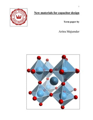
  • 18. 18 Before proceeding to Non-Linear Dielectrics We must get familiar with a special Oxide Structure of our Focus i.e. Perovskite 2.11 Perovskite The family of compounds with general formula ABO3 is generally called perovskite Oxides, as their structure is similar to the naturally obtained mineral CaTiO3. The study on these compounds is important as they find several applications in non-linear optics, memory devices, pyroelectric, piezoelectric sensors etc. apart from the academic point of view due to the physical properties they exhibit. The well-known examples are BaTiO3, PbZrO3, and PbTiO3 etc. The structure is presented in Figure no-5. The coordination number of A-site cation is 12 whereas the coordination number for the B-site ion is 6. Initially, compounds with divalent ions in the A-site and tetravalent ions in B-site were developed. Later on different valent ions were chosen to occupy A and B sites. This structure is also called ‘simple’ perovskite. The structure becomes ‘complex’ if two ions are of different valence and size in A as well as B-sites. This structure is called complex perovskite with the general formula (A’A”)(B’B’’)O3. First attempt on the synthesis of complex perovskite was reported by Galasso and Pyle (1963) and Galasso and Pinto (1965) with the modification in the B-site. The structures that result when there exists perfect ordering in B-site with divalent and penta valent ions in one set of compounds and trivalent and penta valent ions in other set of compounds are given in Figure no-6. (A=Pb and Ba: B’=Mg, Zn, Y, Fe, Nd and Gd etc., and B’’= Nb and Ta). Some of the well-known complex perovskite are Ba (Zn1/3Nb2/3)O3, (Onada (1982) and Colla et al (1993)) Sr(Zn1/3Nb2/3)O3 (Onada (1982) and Colla et al (1993)), (SrxLa1-x)MnO3 (Granado et al (1999)), etc. The nature of dielectric response of these compounds find many applications such as Pb2+ based relaxor ferroelectric transducers, actuators and multilayer capacitors and Ba2+ based dielectric resonator (DR) and microwave band gap structure materials.
  • 19. 19 2.12 Non-Linear Dielectrics The phenomenon of ferroelectricity was discovered in 1921 by J. Valasek who was investigating the dielectric properties of Rochelle salt (NaKC4H4O6.4H2O). Barium titanate (BaTiO3) was discovered to be ferroelectric in 1944 by A von Hippel and is perhaps the most commonly thought of material when one thinks of ferroelectricity. While there are many materials that exhibit ferroelectric properties, some of the more common materials include: Lead titanate PbTiO3, Lead zirconate titanate (PZT), Lead lanthanum zirconate titanate (PLZT). Figure no-18 Figure no-16 Figure no-17
  • 20. 20 2.12.1 Pyroelectric Properties and Spontaneous Polarization all ferroelectric materials are pyroelectric, however, not all pyroelectric materials are ferroelectric. Below a transition temperature called the Curie temperature ferroelectric and pyroelectric materials are polar and possess a spontaneous polarization or electric dipole moment. However, this polarity can be reoriented or reversed fully or in part through the application of an electric field with ferroelectric materials. Complete reversal of the spontaneous polarization is called “switching”. The non-polar phase encountered above the Curie temperature is known as the paraelectric phase. The direction of the spontaneous polarization conforms to the crystal symmetry of the material. While the reorientation of the spontaneous polarization is a result of atomic displacements. The magnitude of the spontaneous polarization is greatest at temperatures well below the Curie temperature and approaches zero as the Curie temperature is neared. Piezoelectric Properties, since all pyroelectric materials are piezoelectric, this means ferroelectric materials are inherently piezoelectric. This means that in response to an applied mechanical load, the material will produce an electric charge proportional to the load. Similarly, the material will produce a mechanical deformation in response to an applied voltage. Properties including the piezoelectric, dielectric and electro optic co- efficient may vary by several orders of magnitude in the narrow temperature band around the Curie temperature. Especially when compared to other temperature ranges, the changes to these co-efficient is much more gradual. The piezoelectric co-efficient is much greater in the region of the Curie temperature. Other properties such as dielectric strength and electro optic properties also change more markedly in the region of the Curie temperature when compared to other temperature ranges. Piezoelectric Effect is the ability of certain materials to generate an electric charge in response to applied mechanical stress. The word Piezoelectric is derived from the Greek piezein, which means to squeeze or press, and piezo, which is Greek for “push”. One of the unique characteristics of the piezoelectric effect is that it is reversible, meaning that materials exhibiting the direct piezoelectric effect (the generation of
  • 21. 21 electricity when stress is applied) also exhibit the converse piezoelectric effect (the generation of stress when an electric field is applied). When piezoelectric material is placed under mechanical stress, a shifting of the positive and negative charge centers in the material takes place, which then results in an external electrical field. When reversed, an outer electrical field either stretches or compresses the piezoelectric material. The piezoelectric effect is very useful within many applications that involve the production and detection of sound, generation of high voltages, electronic frequency generation, microbalances, and ultra-fine focusing of optical assemblies. It is also the basis of a number of scientific instrumental techniques with atomic resolution, such as scanning probe microscopes. The piezoelectric effect also has its use in more mundane applications as well, such as acting as the ignition source for cigarette lighters. 2.12.2 Ferroelectrics To understand the dielectric response of these compounds, one has to probe the micro- structural details (Thomas (1989)). In one set of perovskite systems, the ions displace from their equivalent positions and lead to net dipole moment in the unit cell. The compounds exhibiting this kind of permanent dipole moment are called ferroelectrics. The displacement of ions is cooperative i.e., in the same direction for a set of unit cells. This results in formation of domains (Fatuzzo and Merz (1967)). The ferroelectrics are characterized by well-defined domain structure. The domain structure results in certain unique properties to these systems. The properties are discussed below. The well-defined domain structure in ferroelectrics results in square hysteresis loop, large coercive fields, large remnant polarization (PR) and spontaneous polarization (Ps). Polarization vanishes at transition temperature (Tc). The vanishing is continuous for second order transition while discontinuous for first order transition. The transition from paraelectric to ferroelectric state is sharp in the dielectric response. The temperature dependence of εr obeys Curie-Weiss law above Tc and thermal hysteresis is observed in the dielectric response. No dispersion is observed in the radio frequency region, independent of frequency. Dispersion is observed in microwave region due to domain wall motion. The
  • 22. 22 transition involves change in macroscopic symmetry, which is evidenced from the appearance of shoulders or splitting of certain lines indicating lowering of symmetry. The ferroelectric (FE) transition can be thermodynamically either first order or second order. For transparent Ferroelectrics, a 25 change in the slope is observed at Tc in the temperature variation of the refractive index, n(T). Some materials may not have well defined domain structure due to the reasons discussed later on. One set of such compounds is called relaxor ferroelectrics (Cross (1994) and Samara (Solid state physics, vol. 56.)). Relaxor behavior is observed normally in ferroelectric materials with compositionally induced disorder or frustration. This behavior has been observed and studied most extensively in disordered ABO3 perovskite ferroelectrics and is also seen in mixed crystals of hydrogen-bonded ferroelectrics and anti-ferroelectrics, the photonic glasses. The salient features of the relaxor ferroelectric materials are explained in the following section. 2.12.3 Relaxor ferroelectrics Relaxor ferroelectrics are characterized by slim hysteresis loop, small coercive fields, small remnant polarization (PR) and spontaneous polarization (Ps). Polarization does not vanish at transition temperature but vanishes at higher temperatures called Burns temperature, TB. Relaxor ferroelectrics are characterized by diffused phase transition. The dielectric permittivity of the relaxor attains a maximum value at a temperature Tmax for a particular frequency. As the frequency increases, Tmax increases to higher temperature. The temperature dependence of εr does not obey Curie-Weiss law just above Tmax but obeys beyond TB (TB > Tmax) (Viehland et al (1992)). Thermal hysteresis is not observed in dielectric response. Dispersion is observed in the radio frequency region. The transition does not involve change in macroscopic symmetry. In contrast to the displacive type of ferroelectrics, relaxors do not undergo any structural phase transition as evidenced from X-ray and neutron diffraction studies (de Mathan (1991a), (1991b)). The transition is thermodynamically neither first order nor 26 second order. A change in the slope is observed at TB in the temperature variation of the refractive index, n(T) (Burns and Dacol (1983)). The differences in between ferroelectrics and relaxor ferroelectrics are shown in Figure No-8 & 9. The reason for the differences is attributed to the existence of
  • 23. 23 Polar Regions of Nano size (Burns and Dacol (1983)). The regions are named Polar Regions due to the existence of hysteresis loop and also from the symmetry breaking in these regions as evidenced from X-ray studies. Figure no-19 Figure no-20 Figure no-21 Figure no-22
  • 24. 24 32 Crystalline classes 21 Non-Centro-symmetric 11 Centro-symmetric 20 Classes piezoelectric Non piezoelectric 10 Classes pyroelectric Non Pyroelectric Ferroelectric Non Ferroelectric To summarize the classification of electro-ceramics and elucidate figure no-13, here is a table 2. 2.13 Barium Titanate BaTiO3 is a prototypical ferroelectric material with a characteristic tetragonal distortion of the cubic perovskite structure. The ferroelectric distortion is facilitated by the large size of the Ba cation. Replacement of Ba by the smaller Sr leads to a perovskite with a cubic structure. Is a material of our intended purpose, its relative permittivity/dielectric constant is high 1250 @60 Hz frequency and a high Vb (Table 1). Barium Titanate is ferroelectric. As shown in figure- the local Ti4+ ion is displaced from the center of its octahedral site, accounting for this effect. Table-2 Figure no-23
  • 25. 25 Displacement of atoms in BaTiO3 as a function of an external electric field E. As a consequence of the particular structure, the induced polarization P shows a non-linear behavior with hysteresis. 2.13.1 Impurities and Defects in BaTiO3 Carbonates and hydroxyl groups are the main impurities and defects in BaTiO3 powders. It is likely that BaCO3 is formed during the synthesis of BaTiO3 powder, whichever route is used. Incomplete reaction of BaCO3 or excess of BaCO3 leads to BaCO3 impurity in the BaTiO3 powders prepared by solid state reaction. The hydrothermal synthesis of BaTiO3 is based on the aqueous reaction between Ba and Ti species at a high pH. BaCO3 is always formed as a byproduct due to the atmospheric absorption of CO2 and the high thermodynamic stability of BaCO3 at high pHs in aqueous solutions. However, BaCO3 can be removed by washing BaTiO3 powders with dilute acid solution. Clark et al. reported that as-prepared hydrothermal BaTiO3 contained many defects, primarily in the form of lattice OH- ions. By studying the defects and microstructure of hydrothermal BaTiO3, Hennings et al. pointed out that, in correspondence to the high amount of lattice OH- ions, a large amount of protons existed in the oxygen sublattice. In addition, existence of hydroxyl defects in the perovskite lattices can result in enlarged unit cell volume, which causes a suppression of the tetragonal distortion of the perovskite unit cell at room temperature. 2.13.2 Lead Titanate (PbTiO3, PT) Lead titanate is a ferroelectric material having a structure similar to BaTiO3 with a high Curie point (450°C). On decreasing the temperature through the Curie point a phase transition from the paraelectric cubic phase to the ferroelectric tetragonal phase takes place. Lead titanate ceramics are difficult to fabricate in the bulk form as they undergo a large volume change on cooling below the Curie point, as a result of a phase transformation from cubic to tetragonal in PbTiO3, leading to a strain of >6%. Hence, pure PbTiO3 crack and fracture during fabrication. The spontaneous strain developed during cooling can be reduced by modifying the lead titanate with various dopants such as; Ca, Sr, Ba, Sn, and W to obtain a crack free ceramic [S. Ahmed et al., 2006].
  • 26. 26 2.13.3 Lead Zirconate Titanate {Pb(ZrxTi1-x)O3,PZT} Lead zirconate titanate (PZT) is a binary solid solution of PbZrO3 an anti-ferroelectric (orthorhombic) and PbTiO3 a ferroelectric (tetragonal perovskite structure). PZT has a perovskite type structure with the Ti4+ and Zr4+ ions occupying the B site at random. At high temperature PZT has the cubic perovskite structure, which is paraelectric. On cooling below the Curie point line, the structure undergoes a phase transition to form a ferroelectric tetragonal or rhombohedral phase. In order to suit some specific requirements - 17 - for certain applications, PZT can be modified by doping it with ions having a valance different from the ions in the lattice. PZT can be doped with ions to form "hard" and "soft" PZT's. Hard PZT's are doped with acceptor ions such as k + , Na+ (for A site), Fe3+, Al3+, Mn3+ (for B site), creating oxygen vacancies in the lattice. Hard PZT's usually have lower permittivity, smaller electrical losses and lower piezoelectric coefficients. These are more difficult to pole and depole, which makes them ideal for rugged applications. On the other hand, doping soft PZT's with donor ions such as La3+ (for A site) and Nb5+ , Sb5+ (for B site) lead to the creation of A site vacancies in the lattice. The soft PZT's have higher permittivity, larger losses, higher piezoelectric coefficients, and are easy to pole and depole. They can be used for applications requiring very high piezoelectric properties [S. Ahmed et al., 2006]. 2.13.4 Lead Lanthanum Zirconate Titanate (PLZT) PLZT is a transparent ferroelectric ceramic formed by doping La3+ ions on the A sites of lead zirconate titanate (PZT). The PLZT ceramics have the same perovskite structure as BaTiO3 and PZT. The transparent nature of PLZT has led to its use in electro-optic applications. The two factors that are responsible for getting a transparent PLZT ceramic are: the reduction in the anisotropy of the PZT crystal structure by the substitution of La3+ and the ability to get a pore free ceramic by either hot pressing or liquid phase sintering . The general formula for PLZT is given by (Pb1-xLax)(Zr1-yTiy)1-x/4O3V B 0.25xO3 and (Pb1-xLax)1-0.5x(Zr1-yTiy)VA 0.5xO3. The first formula assumes that
  • 27. 27 La3+ ions go to the A site and vacancies (VB) are created on the B site to maintain charge balance. The second formula assumes that vacancies are created on the A site. The actual structure may be a combination of A and B site vacancies. At room temperature the PLZT have a tetragonal ferroelectric phase (FT), rhombohedral ferroelectric phase (FR), cubic relaxor ferroelectric phase (FC), orthorhombic anti-ferroelectric phase (A0), and a cubic paraelectric phase (PC) [S. Ahmed et al., 2006]. - 18 - The electro-optic applications of PLZT ceramics depend on their composition. PLZT ceramic compositions in the tetragonal ferroelectric phase (FT) region have a hysteresis loop with a very high coercive field (EC). Materials with this composition exhibit linear electro-optic behavior for E<EC. PLZT ceramic compositions in the rhombohedral ferroelectric phase (FR) region of the PLZT phase diagram have loops with low coercive field. These ceramics are useful for optical memory applications. PLZT ceramic compositions with the relaxor ferroelectric behavior are characterized by a slim hysteresis loop. They show large quadratic electro-optic effects which are used for making flash protection goggles to shield from intense radiation. This is one of the biggest applications of the electro-optic effect shown by transparent PLZT ceramics. The PLZT ceramics in the anti-ferroelectric region show a hysteresis loop expected from an anti-ferroelectric material. These components are used for memory applications [S. Ahmed et al., 2006].