Remote control for home appliances
•Télécharger en tant que PPTX, PDF•
25 j'aime•24,497 vues


Recommandé
Recommandé
Contenu connexe
Tendances
Tendances (20)
En vedette
En vedette (20)
Similaire à Remote control for home appliances
Similaire à Remote control for home appliances (20)
Dernier
Dernier (20)
Remote control for home appliances
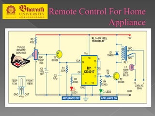
- 3. In this circuit, remote control for home appliance by using IR TSOP1738 sensors. The circuit consists some resistor, capacitor & transistor etc. The circuit work on 5v dc supply and using IC CD4017 decade counter 14 pin.
- 4. S.NO. Component’s Name QuantitiREDes 1. IC CD4017 1 2. IRX TSOP1738 1 3. Transistor BC558(PNP) BC548(NPN) 1 1 4. Resistor --------------------------------- 5. Capacitor --------------------------------- 6. Relay 5v dc 100Ω 1 7. LED <Red & green> 1
- 8. Connect this circuit to any of your home appliances (lamp, fan, radio, etc) to make the appliance turn on/off from a TV, VCD or DVD remote control. The circuit can be activated from up to 10 metres.The 38kHz infrared (IR) rays generated by the remote control are received by IR receiver module TSOP1738 of the circuit. Pin 1 of TSOP1738 is connected to ground, pin 2 is connected to the power supply through resistor R5 and the output is taken from pin3.
- 9. The output signal is amplified by transistor T1 (BC558). The amplified signal is fed to clock pin 14 of decade counter IC CD4017 (IC1). Pin 8 of IC1 is grounded, pin 16 is connected to Vcc and pin 3 is connected to LED1 (red), which glows to indicate that the appliance is ‘off.’
- 10. The output of IC1 is taken from its pin 2. LED2 (green) connected to pin 2 is used to indicate the ‘on’ state of the appliance. Transistor T2 (BC548) connected to pin 2 of IC1 drives relay RL1. Diode 1N4007 (D1) acts as a freewheeling diode. The appliance to be controlled is connected between the pole of the relay and neutral terminal of mains. It gets connected to live terminal of AC mains via normally opened (N/O) contact when the relay energises
- 11. THANK YOU