
Recommandé
Contenu connexe
Tendances
Tendances (20)
Similaire à Emi and emc
Similaire à Emi and emc (20)
Dernier
Dernier (20)
Emi and emc
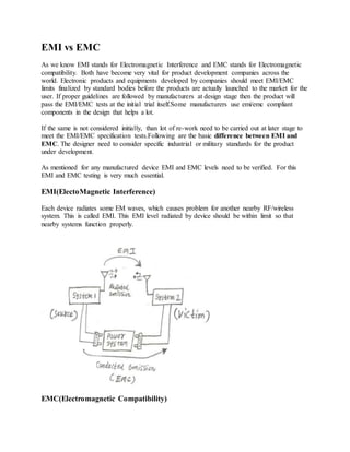
- 1. EMI vs EMC As we know EMI stands for Electromagnetic Interference and EMC stands for Electromagnetic compatibility. Both have become very vital for product development companies across the world. Electronic products and equipments developed by companies should meet EMI/EMC limits finalized by standard bodies before the products are actually launched to the market for the user. If proper guidelines are followed by manufacturers at design stage then the product will pass the EMI/EMC tests at the initial trial itself.Some manufacturers use emi/emc compliant components in the design that helps a lot. If the same is not considered initially, than lot of re-work need to be carried out at later stage to meet the EMI/EMC specification tests.Following are the basic difference between EMI and EMC. The designer need to consider specific industrial or military standards for the product under development. As mentioned for any manufactured device EMI and EMC levels need to be verified. For this EMI and EMC testing is very much essential. EMI(ElectoMagnetic Interference) Each device radiates some EM waves, which causes problem for another nearby RF/wireless system. This is called EMI. This EMI level radiated by device should be within limit so that nearby systems function properly. EMC(Electromagnetic Compatibility)
- 2. Each device generates electric noise which passes through cables/wires and cause problem for another device connected with the same electric system. This conducted emissions(transients/ripples) should be within limit for proper functioning of the another device/system. This is called as EMC level. There are many forms of electromagnetic interference, EMI that can affect circuits and prevent them from working in the way that was intended. This EMI or radio frequency interference, RFI as it is sometimes called can arise in a number of ways, although in an ideal world it should not be present. EMI - electromagnetic interference can arise from many sources, being either man made or natural. It can also have a variety of characteristics dependent upon its source and the nature of the mechanism giving rise to the interference. By the very name of interference given to it, EMI is an unwanted signal at the signal receiver, and in general methods are sought to reduce the level of the interference. Types of EMI - Electromagnetic Interference EMI - Electromagnetic Interference can arise in many ways and from a number of sources. The different types of EMI can be categorised in a number of ways. One way of categorising the type of EMI is by the way it was created: Man-made EMI: This type of EMI generally arises from other electronics circuits, although some EMI can arise from switching of large currents, etc. Naturally occurring EMI: This type of EMI can arise from many sources - cosmic noise as well as lightning and other atmospheric types of noise all contribute. Another method of categorising the type of EMI is by its duration: Continuous interference: This type of EMI generally arises from a source such as a circuit that is emitting a continuous signal. However background noise, which is continuous may be created in a number of ways, either manmade or naturally occurring. Impulse noise: Again, this type of EMI may be man-made or naturally occurring. Lightning, ESD, and switching systems all contribute to impulse noise which is a form of EMI. It is also possible to categorise the different types of EMI by their bandwidth. Narrowband: Typically this form of EMI is likely to be a single carrier source - possibly generated by an oscillator of some form. Another form of narrowband EMI is the spurious signals caused by intermodulation and other forms of distortion in a transmitter such as a mobile phone of Wi-Fi router. These spurious signals will appear at different points in the spectrum and may cause interference to another user of the radio spectrum. As such these spurious signals must be kept within tight limits.
- 3. Broadband: There are many forms of broadband noise which can be experienced. It can arise from a great variety of sources. Man-made broadband interference can arise from sources such as arc welders where a spark is continuously generated. Naturally occurring broadband noise can be experienced from the Sun - it can cause sun-outs for satellite television systems when the Sun appears behind the satellite and noise can mask the wanted satellite signal. Fortunately these episodes only last for a few minutes. EMI coupling mechanisms There are many ways in which the electromagnetic interference can be coupled from the source to the receiver. Understanding which coupling method brings the interference to the receiver is key to being able to address the problem. Radiated: This type of EMI coupling is probably the most obvious. It is the type of EMI coupling that is normally experienced when the source and victim are separated by a large distance - typically more than a wavelength. The source radiates a signal which may be wanted or unwanted, and the victim receives it in a way that disrupts its performance. Conducted : Conducted emissions occur as the name implies when there is a conduction route along which the signals can travel. This may be along power cables or other interconnection cabling. The conduction may be in one of two modes: o Common mode: This type of EMI coupling occurs when the noise appears in the same phase on the two conductors, e.g. out and return for signals, or +ve and -ve for power cables. o Differential mode: This occurs when the noise is out of phase on the two conductors. The filtering techniques required will vary according to the type of EMI coupling experienced. For common mode lines are filtered together. For differential mode they may be filtered together. Inductive coupling: What is normally termed inductive coupling can be one of two forms, namely capacitive coupling and magnetic induction. Capacitive coupling : This occurs when a changing voltage from the source capacitively transfers a charge to the victim circuitry. Magnetic coupling: This type of EMI coupling exists when a varying magnetic field exists between the source and victim - typically two conductors may run close together (less than λ apart). This induces a current in the victim circuitry, thereby transferring the signal from source to victim. By determining the form of coupling that exists and the way in which it is reaching the victim, it may prove to be that the most effective method of reducing the EMI is by putting measures in place to reduce the coupling and reduce the level of interference to an acceptable level.
- 4. Electromagnetic interference, EMI is present in all areas of electronics. By understanding the source, the coupling methods and the susceptibility of the victim, the level of interference can be reduced to a level where the EMI causes no undue degradation in performance. What is EMI/EMC? EMI/EMC is the acronym of ElectroMagnetic Interference/Compatibility. Its concern is the ability of electronic equipment to work satisfactorily in the electromagnetic environment (immunity) without introducing intolerable electromagnetic interference to that environment (emission). Computer screen distortion caused by your cellular phone, cross-talk between phone lines, and electrostatic discharge (ESD) are some examples of EMI problems. EMC is concerned with the generation, transmission and reception of electromagnetic energy. These three aspects of the EMC problem form the basic framework of any EMC design. A source (also referred to as an emitter) produces the emission, and a transfer or coupling path transfers the emission energy to a receptor (receiver), where it is processed, resulting in either desired or undesired behavior. Interference occurs if the received energy causes the receptor to behave in an undesired manner. Importance of EMC EMC has become increasingly important recently because of its wide ranging industrial and more general societal (for instance medical) implications. Meeting EMC standards is a basic requirement for any electrical and electronical device before placement on the market. EMC problems are thus main concerns of the telecommunication, electronics, automobile industry. EMC Testing There are four types of EMC test: radiated emission, radiated immunity, conducted emisssion and conducted immunity. The radiated emission test system includes equipment under test (EUT), an antenna and the signal analysis device. The induced voltage from antenna is measured and the data is used to calculate the field strength by antenna factor. An immunity test, requires an electromagnetic source to generate the desired environment. This source is linked to the EUT either by radiated or by conducted method. Additionally, a monitor is required to know if the EUT is working well.