SlideShare une entreprise Scribd logo
1  sur  14
Télécharger pour lire hors ligne
500r+
Installation and User Guide

Compatible Equipment
502rUK-50
509rUK-50
515rUK-00
525rUK-00
535rUK-00
545rUK-00
546rUK-00
8440UK-01
660UK-00
09040UK-00

Watch/Pendant PA.
Smoke Detector
10 metre passive infra red movement detector.
Remote Set/Unset (Full and Part Set) unit plus PA facility.
Universal/door contact transmitter.
Radio Signal Strength Meter.
Test Transmitter.
4-Channel Digital Communicator.
4 channel wire in speech communicator.
16 Ohm loudspeaker/sounder.

496361 Issue 1

1 of 14
500r+

Introduction
The 500r+ is a programmable Radio Alarm System designed specifically for
domestic and small business premises. The 500r+ provides eight zones with
PA on a dedicated zone.
A basic system comprises a control unit with built in keypad, and associated
radio detectors. The control unit houses the system electronics, power
supply, battery, and 660 Speech Communicator (if fitted). A numeric keypad
and two rows of Light Emitting Diodes (LEDs) allow the user and installer to
operate the system. Up to six remote setting devices can also be used on the
500r+ to set or unset the system, and act as Personal Attack alarms.
Each detector and remote setting device contains a digital identity code that
the control unit ‘learns’ during installation. The code is one of over 16 million
possibilities. This ensures that the control unit will not respond to any other
detectors or remote setting switches apart from the ones it has learned.
The radio operating frequency between the control unit receiver and the
detectors is 418MHz with a bandwidth of 200kHz. The radio section is approved to MPT 1340.
The 500r+ system is designed to meet the requirements of BS6799 Class
“III” and complies with all current NACOSS codes of practice for domestic
and small business Audible ONLY intruder alarm systems. The system can
be certified by approved installers as a Wirefree “Class III” installation.

2 of 14

496361 Issue 1
500r+

Technical Specification
Zones (500r+)
Display
Keypads
Expansion
Compliance
Radio Section
Radio section
Log
Control unit Siren
Internal Sounder
Battery
12V power
Aux DC power
Dimensions
Weight
Communicator

Outputs

8 wirefree, plus PA. PA can use up to six
502r or 525r.
LED.
On-board + Remote Set/Unset using 525r,
up to 6 per control unit.
None.
Product is CE tested to EN 50081-1 and EN
50082-1.
Operating frequency 418 MHz at 200 kHz
bandwidth.
CE tested to I-ETS 300 339 (draft standard).
16 events.
Yes (approx. 80db at 1 metre).
1 x 9040 16 Ohm loudspeaker (approx. 90db
at 1 metre).
1.9(2.1)Ah lead acid gel type rechargeable.
Control unit quiescent current 55mA.
500mA max at 12V in alarm state.
h x w x d = 163 x 257 x 74 mm.
1.2 kg.
50mA max PA and Burg outputs for 660
Speech Communicator or 8440 Digital
Communicator. Positive removed in alarm.
Bell and Strobe (negative applied (SAB))
500mA total output.

496361 Issue 1

3 of 14
500r+

Wiring
External Bell
Figure 9 shows an example of connections for a typical external bell (see the
manufacturers instructions supplied with individual units for further information on wiring diagrams).

Figure 9. Typical External Sounder Connections
Make connections to the control unit and SAB module as follows:
STR
Negative trigger in alarm for strobe light.
BELL
Negative bell trigger.
12V
Positive bell module hold off voltage (Supply).
0V
Negative bell module hold off (Supply).
TR
Negative tamper return from bell module to control unit.
Notes:
1. SAB shown for negative applied.
2. Link tamper return to 0V if no external bell is required.
3. Connect all bell wiring to the control unit with the exception of the bell
trigger. The bell/siren will continue to ring from the on-board battery until the
final connections are made after initial power-up. See ‘Programming - Initial
Power Up’.

4 of 14

496361 Issue 1
500r+

Fitting a 660 or 8440 Communicator

Fitting a 660 or 8440 Communicator

Figure 10. 660 or 8440 Communicator Connections
The output connectors available are:
OP1
Burglar output - positive removed in alarm (+12V, 50mA
max).
OP2
PA output - positive removed in alarm (+12V, 50mA max).
Fit the communicators inside the back casing. Locate the communicator
toward the top left of the back box.
Note: Do not connect the 12V supply to the communicator until after the initial power
up. See ‘Programming’.

496361 Issue 1

5 of 14
500r+

Programming
Initial Power Up
Note: Before applying power to the control unit ensure that the bell trigger is not
connected to any external sounders, or 12V supply connected to the 660
Speech Communicator (if fitted).

1.
2.
3.
4.
5.

Close the control unit lid or defeat lid tamper.
Apply mains power to the control unit.
Key in the default user code (1234) if there is an alarm. Ignore any
LEDs that are lit at this stage.
Key in the engineer code (default 7890).
The Standby LED flashes.
Open the control unit lid or release control unit tamper.
The a (Power) LED goes off and the Standby LED glows steadily. The
control unit gives a double bleep.
You are now in Programming mode.

6.

Connect the battery and make any final wired connections (for example
to the bell and 660 Speech Communicator).

Learning Detectors (Command 81)
You must make the control unit learn the identity of each detector in the
system and link them to zones. To do this:
1. Enter programming mode if you have not done so already.
2. Enter 81 on the keypad.
The Standby LED flashes. The LEDs of zones that already have detectors flash. The LEDs of zones with no detectors glow steadily. The
contol unit uses the PA LED for any 502r or 525r’s.
3.

Enter the number of the zone you want the control unit to learn (use 9
for a 502r or 525r).
The LED of the zone you selected flashes, all the other zone LEDs go
out (the PA LED flashes if you selected 9).

4.

Point the activity LED of the detector at the Learn sensor on the control
unit (marked by Learn). Hold the activity LED of the detector close to the
sensor.
Trigger the detector by operating the tamper, or press a button on the
502r or 525r.

5.

6 of 14

496361 Issue 1
500r+

Deleting Detectors

The activity LED on the detector flashes, and transmits an identity code
to the Learn sensor. The control unit gives a short double beep when it
learns the code.
6.

Repeat steps 3 to 5 for any other detectors you want the control unit to
learn.

Notes:
1. The default factory setting is Zone 1 as the Entry/Exit zone.
2. The control unit will not learn the same detector more than once.
3. The control unit can learn a total of six 502r or 525r’s in any combination.
Each device uses the PA zone (9).

Deleting Detectors (Command 82)
If you wish to change detectors then the control unit cannot learn a new
detector for a zone that is already in use. You must delete the existing detector first, as follows:
1. Enter programming mode if you have not already done so.
2. Enter 82 on the keypad.
The Standby LED flashes. The LEDs of zones that already have detectors glow steadily. The LEDs of zones with no detectors stay off. The
control unit uses the PA LED for any 502r or 525r’s.
3.

Enter the number of the zone you want to delete (use 9 for 502r and
525r’s).
The LED of the zone you selected flashes.

Note: The control unit deletes all 502r and 525r’s if you select ‘9’.

4.

Press 8 on the keypad.
The LED of the zone you selected goes out and the control unit gives a
double bleep.

5.

Repeat steps 2 to 4 for any other detectors you want to delete.

Programming Commands
To change the factory default program, use the commands listed in this
section as follows:
1. Enter the command number.
The Alarm LED flashes if the current program is the factory default.
2.
3.

Enter one or more digits to give the new progam.
Press Reset.

496361 Issue 1

7 of 14
Program Commands

500r+

The control unit will give a double bleep to show it has accepted the
command. If you enter the command incorrectly the control unit gives a
single low bleep.
When delivered from the factory, the control unit is programmed with standard defaults for each command. A “Y ” in the right hand column of the table
shows the default.
To change:
Key in: Followed by:
Default
Engineering Walk Test
71 (see “5. Testing”)
Change User Code
72 New user code (four digits)
1234
View Log
73 (see “Testing”)
Test Strobe
74 (see “Testing”)
Test Siren
75 (see “ Testing”)
Add Detector
81 (see ”Learning Detectors”)
none
Delete Detector
82 (see “Deleting Detectors”)
Burg O/P Follows Bell
84 1 + Reset = Yes
Omit + Reset =No

Y

Entry/Exit Time
Bell Duration
Strobe follows bell

86 A number 10 to 99 seconds + Reset.
30s
87 A number 01 to 20 minutes + Reset. 20 mins
88 1 + Reset = Yes.

Engineer Code
Remote Unset

89 New four digit code. Do not use 0 (zero)
for the first digit.
7890
90 1 + Reset = No entry timer required.

Bell Delay

91 A number 01 to 30 minutes + Reset.

System Reset

92 1 + Reset = Engineer only.

Entry Route Zone

93 Zone number(s) 2 to 8 + Reset.

PA Response

94 1 + Reset = Silent.

Omit Allowed

95 1 + Reset = No.

Additional E/Exit Zones

96 Zone number(s) 2 to 8 + Reset.

Tamper response

97 1 + Reset = Full alarm in user mode.

Omit + Reset = Continuous.

Omit + Reset = Needs entry timer.
Omit + Reset + Reset = nil.
Omit + Reset = Customer reset.
Omit + Reset = None.
Omit + Reset = Audible.
Omit + Reset = Yes.
Omit + Reset = Zone 1 only.
Omit + Reset = Internal alarm in user mode.

Restore Factory Defaults
Leave Programming

8 of 14

98 Omit + Omit + Omit
99 Reset

496361 Issue 1

Y

Y
Y
Y
Y
Y
Y
Y
Y
500r+

Restoring Factory Default Program

Restoring Factory Default Program (Command 98)
If you want to restore all the programming to the original factory defaults,
then:
1. Enter 98.
The control unit bleeps once every second.
2.

Press Omit three times.
The control unit gives a double bleep, erases all the programs the user
and previous engineers have entered, and restores the original factory
defaults.

Note: The control unit will still remember any detectors that it has learned.

Leaving Programming Mode (Command 99)
The control unit will stay in programming mode until you enter a command to
return it to user mode, as follows:
1. Close control unit lid.
2. Enter 99.
The a and Standby LEDs glow steadily. The control unit is now in user
mode.

To Re-enter Programming Mode
1.
2.

Make sure the control unit is unset.
Enter Engineer Code.
The Standby LED flashes.

3.

Open the control unit lid.
The control unit gives a double bleep, the a LED goes out and the
Standby LED glows steadily. The control unit is now in programming
mode.

Clearing a Control unit For a New User
To remove all programming, including detectors and Engineer and User
codes (perhaps to reuse the control unit with another user) then, while the
control unit is unset:
1. Open the lid.
2. Remove the mains supply and disconnect the Battery.
3. Short together the two middle CLR pins on the NVM
Reset pin block and reconnect battery supply.
The control unit restores all its programming to the factory
default settings, and deletes all detectors.
496361 Issue 1

9 of 14
Changing the User Code

4.
5.
6.
7.

500r+

Remove the short after two seconds.
Restore the mains supply.
Close the lid.
Enter 1234 and press Reset.

Note: To restore all the programming apart from the learnt detectors, repeat steps 1
to 7 above, but at 3. short together the top two LOAD DFLTS pins.

Changing the User Code
You can change the user access code while in programming mode. To do
this:
1. Enter programming mode.
2. Enter 7 2.
The LEDs for zones 5, 6, 7 and 8 light up.
3.

Key in the new user code (four digits).
Each time you key in a digit of the user access code one of the 5, 6, 7,
or 8 LEDs goes out.

4.

Leave programming mode.

5. Testing
Testing Detectors
Make sure the system is in programming mode.
1. Enter 71.
All LEDs light for 2 seconds, and then the control unit enters walk test
mode.
2.

Activate each 502r, 525r (PA function only), and detector. You may also
test detector tampers.
When the control unit receives the detector it gives a chime tone and
turns the relevant zone LED on for five seconds. The control unit turns
on the Alarm and Tamper LEDs when you activate the tampers. When
you activate the 502r Watch Pendant or the PA function on the 525r
Remote Setting Device the control unit gives a chime tone and lights the
PA LED for five seconds.

3.

Press Reset to end the walk test.

PIR Testing and Lockout
In normal use the 515r uses a three minute lockout timer in order to extend
battery life.The lockout timer works like this:

10 of 14

496361 Issue 1
500r+

Testing Siren and Strobe

a)

The unit detects movement, signals the panel, and starts the lockout
timer.
b)
If the unit detects movement while the lockout timer is running, then it
restarts the lockout timer but DOES NOT signal the panel.
c)
When the lockout timer expires the unit signals the panel the next time
it detects movement.
If you want to test a 515r PIR in normal use you should leave the protected
area and wait at least four minutes between activations. To make testing
easier the detector changes the lockout period to 10 seconds for the first half
hour after you put the batteries in, or after you trigger its tamper.
Note: Make sure the control unit is in programming mode before you open or move
any of the detectors. This will avoid setting the tamper alarm off.

Testing Siren and Strobe
Make sure the system is in programming mode.
1. Enter 75.
The control unit activates the siren.
3.

Press Reset.
The control unit silences the bell (the control unit will silence the bell
after 30 seconds if you do not press Reset).

4.

Enter 74.
The control unit triggers the strobe.

6.

Press Reset.
The control unit switches the strobe off (the control unit will switch the
strobe off after 30 seconds if you do not press Reset).

Examining the Log
The control unit keeps a record of the last 16 events. You can examine this
record, starting with the most recent event, as follows:
1. Make sure the system is in programming mode.
2. Enter 73.
The display LEDs show the most recent event.
4.

Press 3 repeatedly.
The display shows an earlier event in the list each time you press 3. The
control unit gives a low tone when it reaches the end of the list.

5.

Press Reset.

496361 Issue 1

11 of 14
500r+

The system goes back to program mode (the control unit will switch
itself back to program mode after 30 seconds if you do not press any
key).

6. Fault Finding
Symptom

Response

• FAULT TONE AND a FLASHES CONTINUOUSLY.

• Mains supply has failed, control unit operating from battery only. (If
Fault tone present mains failed over 1 hour ago.)
• Check mains connection and fuse.

• TAMPER FLASHES, CONTROL UNIT WILL NOT

• Check connections and ensure external sounder tamper switch is

RESET.

fully closed. Ensure cover on External sounder is secure.

FAULT TONE, LOW BATT AND PA LED ON.

• Low battery in 502r or 525r indicated - replace battery.

FAULT TONE, LOW BATT AND ZONE LED ON.

• Low battery in detector indicated - replace battery.

• CANNOT LEAVE PROGRAMMING MODE.

• Tamper on steadily - control unit tamper not closed.

(System can still be armed with low battery indication.)

(System can still be armed with low battery indication.)

• TAMPER (AND POSSIBLY ZONE) LED ON.

• Tamper flashing - External sounder tamper not closed.
• Zone LED with Tamper - detector open or not screwed down firmly.
• Clear fault. Press Reset (Standby will glow steadily).
• Key in 99 (a and Standby glow steadily).

• RF TROUBLE LED FLASHING.

• Control unit detecting interference on same frequency as detectors.
• Wait till RF Trouble goes out. If problem persists, call Scantronic
Technical Support.

• PIR DOES NOT DETECT MOVING PERSON
(NO RED LIGHT).

• To save power, after each activation the PIR ‘sleeps’ for three
minutes. Any movement during the three minutes will extend the
sleep period by another three minutes. See PIR Installation Guide.
• Check detector battery.

• PIR DOES NOT APPEAR TO TRANSMIT
IMMEDIATELY WHEN DETECTION TAKES

• This is normal. The PIR may take up to two seconds (variable)
to transmit after detecting a moving person.

PLACE.
• WHEN DOOR OPENED, TAMPER
AND ZONE LEDS FLASH

• Detector case not properly closed, or not screwed down fully to
close front or back tamper switch.

AND INTERNAL ALARM SOUNDS.
• SAB WILL NOT STOP RINGING.

• SAB not receiving power.
• Check fuse F1.
• Check tamper switch on external sounder.
• Ensure cover on External sounder is secure.

12 of 14

496361 Issue 1
500r+

User Commands

First to Alarm Indication
When several alarm events occur before the user can reset the system, the
control unit indicates which event occured first. It does this by flashing LEDs
lit by the first event, and lighting LEDs steadily for subsequent events. For
example, if the control unit detects a tamper on zone 2 followed by a violation
on zone 3, then the Tamper and zone 2 LEDs flash, while the Alarm and
zone 3 LEDs glow steadily.

User Commands
From the Keypad
Full Set

User code + ENTER.

Unset

User code.

Part Set

User code + OMIT + zone number + ENTER.

Silence Bells

User code.

Reset

Press RESET.

Change User Code

User code + 2 + old code + new code.

Read log

User code + 3 + 3 (to read earlier events) + 0 (to
end log).

Walk Test

User code + 1 + activate detectors + 0 to end test.

Test Bell

User code + 5 + 0 to end test.

Test Strobe

User code + 4 + 0 to end test.

From the 525 Remote Setting Device
Full Set

Press Arm.

Part Set

Press Night (system sets omitting any zones
previously omitted using the keypad).

Unset

Press Off.

PA

Press Arm and Off together.

496361 Issue 1

13 of 14
14 of 14

496361 Issue 1

Contenu connexe

Tendances

V350-35-RA22_INSTAL-GUIDE_10-08
V350-35-RA22_INSTAL-GUIDE_10-08V350-35-RA22_INSTAL-GUIDE_10-08
V350-35-RA22_INSTAL-GUIDE_10-08Cara Bereck Levy
 
Manual heatit z-water_analog inputs_fw 2.1_ver2019-a_eng
Manual heatit z-water_analog inputs_fw 2.1_ver2019-a_engManual heatit z-water_analog inputs_fw 2.1_ver2019-a_eng
Manual heatit z-water_analog inputs_fw 2.1_ver2019-a_engDomotica daVinci
 
manual vision siren VIS_ZM1601
manual vision siren VIS_ZM1601manual vision siren VIS_ZM1601
manual vision siren VIS_ZM1601Domotica daVinci
 
Qubino flush heat__cool_thermostat_user-manual_v1.2_eng
Qubino flush heat__cool_thermostat_user-manual_v1.2_engQubino flush heat__cool_thermostat_user-manual_v1.2_eng
Qubino flush heat__cool_thermostat_user-manual_v1.2_engDomotica daVinci
 
Manual Steinel l 810 led i hf (outdoor light with led)
Manual Steinel l 810 led i hf (outdoor light with led)Manual Steinel l 810 led i hf (outdoor light with led)
Manual Steinel l 810 led i hf (outdoor light with led)Domotica daVinci
 
Manual heatit z-din 616_eng
Manual heatit z-din 616_engManual heatit z-din 616_eng
Manual heatit z-din 616_engDomotica daVinci
 
Advanced motion controls azbe12a8
Advanced motion controls azbe12a8Advanced motion controls azbe12a8
Advanced motion controls azbe12a8Electromate
 
wiDom Multi Sensor Room Controller MSRC Manual EN
wiDom Multi Sensor Room Controller MSRC Manual ENwiDom Multi Sensor Room Controller MSRC Manual EN
wiDom Multi Sensor Room Controller MSRC Manual ENDomotica daVinci
 
Operating manual radiator thermostat Fibaro
Operating manual radiator thermostat FibaroOperating manual radiator thermostat Fibaro
Operating manual radiator thermostat FibaroDomotica daVinci
 
Universal modules TXM1.8x Siemens
Universal modules TXM1.8x SiemensUniversal modules TXM1.8x Siemens
Universal modules TXM1.8x SiemensJustin Hoang
 
Z-stick USB wave plus - aeon - manual
Z-stick USB wave plus - aeon - manualZ-stick USB wave plus - aeon - manual
Z-stick USB wave plus - aeon - manualDomotica daVinci
 
Qubino smart plug 16 A Z-Wave Plus manual
Qubino smart plug 16 A Z-Wave Plus manualQubino smart plug 16 A Z-Wave Plus manual
Qubino smart plug 16 A Z-Wave Plus manualDomotica daVinci
 
Advanced motion controls be40a8i
Advanced motion controls be40a8iAdvanced motion controls be40a8i
Advanced motion controls be40a8iElectromate
 

Tendances (20)

V350-35-RA22_INSTAL-GUIDE_10-08
V350-35-RA22_INSTAL-GUIDE_10-08V350-35-RA22_INSTAL-GUIDE_10-08
V350-35-RA22_INSTAL-GUIDE_10-08
 
Manual heatit z-water_analog inputs_fw 2.1_ver2019-a_eng
Manual heatit z-water_analog inputs_fw 2.1_ver2019-a_engManual heatit z-water_analog inputs_fw 2.1_ver2019-a_eng
Manual heatit z-water_analog inputs_fw 2.1_ver2019-a_eng
 
Mh7 eu um v.02
Mh7 eu um v.02Mh7 eu um v.02
Mh7 eu um v.02
 
manual vision siren VIS_ZM1601
manual vision siren VIS_ZM1601manual vision siren VIS_ZM1601
manual vision siren VIS_ZM1601
 
Qubino flush heat__cool_thermostat_user-manual_v1.2_eng
Qubino flush heat__cool_thermostat_user-manual_v1.2_engQubino flush heat__cool_thermostat_user-manual_v1.2_eng
Qubino flush heat__cool_thermostat_user-manual_v1.2_eng
 
Manual Steinel l 810 led i hf (outdoor light with led)
Manual Steinel l 810 led i hf (outdoor light with led)Manual Steinel l 810 led i hf (outdoor light with led)
Manual Steinel l 810 led i hf (outdoor light with led)
 
Manual zxt 600
Manual zxt 600Manual zxt 600
Manual zxt 600
 
5808spec
5808spec5808spec
5808spec
 
Aeotec led bulb manual
Aeotec led bulb manualAeotec led bulb manual
Aeotec led bulb manual
 
Manual heatit z-din 616_eng
Manual heatit z-din 616_engManual heatit z-din 616_eng
Manual heatit z-din 616_eng
 
Mh8 fc um
Mh8 fc umMh8 fc um
Mh8 fc um
 
Advanced motion controls azbe12a8
Advanced motion controls azbe12a8Advanced motion controls azbe12a8
Advanced motion controls azbe12a8
 
wiDom Multi Sensor Room Controller MSRC Manual EN
wiDom Multi Sensor Room Controller MSRC Manual ENwiDom Multi Sensor Room Controller MSRC Manual EN
wiDom Multi Sensor Room Controller MSRC Manual EN
 
Manual SEC_SCS318 secure
Manual SEC_SCS318 secureManual SEC_SCS318 secure
Manual SEC_SCS318 secure
 
Hx711 english
Hx711 englishHx711 english
Hx711 english
 
Operating manual radiator thermostat Fibaro
Operating manual radiator thermostat FibaroOperating manual radiator thermostat Fibaro
Operating manual radiator thermostat Fibaro
 
Universal modules TXM1.8x Siemens
Universal modules TXM1.8x SiemensUniversal modules TXM1.8x Siemens
Universal modules TXM1.8x Siemens
 
Z-stick USB wave plus - aeon - manual
Z-stick USB wave plus - aeon - manualZ-stick USB wave plus - aeon - manual
Z-stick USB wave plus - aeon - manual
 
Qubino smart plug 16 A Z-Wave Plus manual
Qubino smart plug 16 A Z-Wave Plus manualQubino smart plug 16 A Z-Wave Plus manual
Qubino smart plug 16 A Z-Wave Plus manual
 
Advanced motion controls be40a8i
Advanced motion controls be40a8iAdvanced motion controls be40a8i
Advanced motion controls be40a8i
 

En vedette

Kele Gas & Specialty Sensors
Kele Gas & Specialty SensorsKele Gas & Specialty Sensors
Kele Gas & Specialty SensorsKele, Inc.
 
Teletek fire catalog_eng
Teletek fire catalog_engTeletek fire catalog_eng
Teletek fire catalog_engAlin Mustata
 
Matrix Security Solutions: PROPAC
Matrix Security Solutions: PROPAC Matrix Security Solutions: PROPAC
Matrix Security Solutions: PROPAC Matrix Comsec
 
Codigos y perifericos rep 2001
Codigos y perifericos rep 2001Codigos y perifericos rep 2001
Codigos y perifericos rep 2001Jesus Ciau
 
Honeywell is25100tc-spec-sheet
Honeywell is25100tc-spec-sheetHoneywell is25100tc-spec-sheet
Honeywell is25100tc-spec-sheetAlarm Grid
 
Home security systems
Home security systemsHome security systems
Home security systemsVisonic
 

En vedette (7)

Kele Gas & Specialty Sensors
Kele Gas & Specialty SensorsKele Gas & Specialty Sensors
Kele Gas & Specialty Sensors
 
Sentox
SentoxSentox
Sentox
 
Teletek fire catalog_eng
Teletek fire catalog_engTeletek fire catalog_eng
Teletek fire catalog_eng
 
Matrix Security Solutions: PROPAC
Matrix Security Solutions: PROPAC Matrix Security Solutions: PROPAC
Matrix Security Solutions: PROPAC
 
Codigos y perifericos rep 2001
Codigos y perifericos rep 2001Codigos y perifericos rep 2001
Codigos y perifericos rep 2001
 
Honeywell is25100tc-spec-sheet
Honeywell is25100tc-spec-sheetHoneywell is25100tc-spec-sheet
Honeywell is25100tc-spec-sheet
 
Home security systems
Home security systemsHome security systems
Home security systems
 

Similaire à 500plus

Programmable Home Security Alarm System
Programmable Home Security Alarm SystemProgrammable Home Security Alarm System
Programmable Home Security Alarm SystemDilshan Jayakody
 
Manual 10 year smoke detector Z-Wave Plus-Popp
Manual 10 year smoke detector Z-Wave Plus-PoppManual 10 year smoke detector Z-Wave Plus-Popp
Manual 10 year smoke detector Z-Wave Plus-PoppDomotica daVinci
 
Manual de instalacion detector honeywell
Manual de instalacion detector honeywellManual de instalacion detector honeywell
Manual de instalacion detector honeywellCésar Ortiz Rincón
 
HST New Fire Alarm System
HST New Fire Alarm SystemHST New Fire Alarm System
HST New Fire Alarm Systemssuser7165ec
 
Qubino flush dimmer 0 10-v plus user manual_v1.0_eng
Qubino flush dimmer 0 10-v plus user manual_v1.0_engQubino flush dimmer 0 10-v plus user manual_v1.0_eng
Qubino flush dimmer 0 10-v plus user manual_v1.0_engDomotica daVinci
 
SenseTek Stratos Micra 25 installers handbook
SenseTek Stratos Micra 25 installers handbookSenseTek Stratos Micra 25 installers handbook
SenseTek Stratos Micra 25 installers handbookHans Bronkhorst
 
ASESIndia Analog Addressable Fire Alarm System
ASESIndia  Analog Addressable Fire Alarm SystemASESIndia  Analog Addressable Fire Alarm System
ASESIndia Analog Addressable Fire Alarm SystemASES Security Pvt. Ltd.
 
830 and 708 wireless fire alarm system control panel introduction
830 and 708 wireless fire alarm system control panel introduction830 and 708 wireless fire alarm system control panel introduction
830 and 708 wireless fire alarm system control panel introductionVedard Security Alarm System Store
 
System sensor 1400 manual i56-0279
System sensor 1400 manual i56-0279System sensor 1400 manual i56-0279
System sensor 1400 manual i56-0279Henry Rosa
 
Manual co detector-popp_en
Manual co detector-popp_enManual co detector-popp_en
Manual co detector-popp_enDomotica daVinci
 
Alarm Annunciator
Alarm AnnunciatorAlarm Annunciator
Alarm AnnunciatorESD India
 
iLumTech Connected lighting
iLumTech Connected lightingiLumTech Connected lighting
iLumTech Connected lightingiLumTech
 
Manual ES-12-ZIP-PD01Z PIR Z-Wave Plus motion sensor
Manual ES-12-ZIP-PD01Z PIR Z-Wave Plus motion sensorManual ES-12-ZIP-PD01Z PIR Z-Wave Plus motion sensor
Manual ES-12-ZIP-PD01Z PIR Z-Wave Plus motion sensorDomotica daVinci
 
Manual Smoke Sensor 10 years autonomy - Popp
 Manual Smoke Sensor 10 years autonomy - Popp Manual Smoke Sensor 10 years autonomy - Popp
Manual Smoke Sensor 10 years autonomy - PoppDomotica daVinci
 
Manual 10 year smoke detector Z-Wave Plus-Popp
Manual 10 year smoke detector Z-Wave Plus-PoppManual 10 year smoke detector Z-Wave Plus-Popp
Manual 10 year smoke detector Z-Wave Plus-PoppDomotica daVinci
 
SenseTek Stratos Micra 100 installers handbook
SenseTek Stratos Micra 100 installers handbookSenseTek Stratos Micra 100 installers handbook
SenseTek Stratos Micra 100 installers handbookHans Bronkhorst
 

Similaire à 500plus (20)

Programmable Home Security Alarm System
Programmable Home Security Alarm SystemProgrammable Home Security Alarm System
Programmable Home Security Alarm System
 
Mini 2 zones Conventional Fire Alarm Control Panel
Mini 2 zones Conventional Fire Alarm Control PanelMini 2 zones Conventional Fire Alarm Control Panel
Mini 2 zones Conventional Fire Alarm Control Panel
 
Manual 10 year smoke detector Z-Wave Plus-Popp
Manual 10 year smoke detector Z-Wave Plus-PoppManual 10 year smoke detector Z-Wave Plus-Popp
Manual 10 year smoke detector Z-Wave Plus-Popp
 
Manual de instalacion detector honeywell
Manual de instalacion detector honeywellManual de instalacion detector honeywell
Manual de instalacion detector honeywell
 
HST New Fire Alarm System
HST New Fire Alarm SystemHST New Fire Alarm System
HST New Fire Alarm System
 
TS52 PRO LCD Test Set
TS52 PRO LCD Test SetTS52 PRO LCD Test Set
TS52 PRO LCD Test Set
 
Tx7110 heat detector
Tx7110 heat detectorTx7110 heat detector
Tx7110 heat detector
 
Qubino flush dimmer 0 10-v plus user manual_v1.0_eng
Qubino flush dimmer 0 10-v plus user manual_v1.0_engQubino flush dimmer 0 10-v plus user manual_v1.0_eng
Qubino flush dimmer 0 10-v plus user manual_v1.0_eng
 
SenseTek Stratos Micra 25 installers handbook
SenseTek Stratos Micra 25 installers handbookSenseTek Stratos Micra 25 installers handbook
SenseTek Stratos Micra 25 installers handbook
 
ASESIndia Analog Addressable Fire Alarm System
ASESIndia  Analog Addressable Fire Alarm SystemASESIndia  Analog Addressable Fire Alarm System
ASESIndia Analog Addressable Fire Alarm System
 
CATV Optical Transmitter
CATV Optical TransmitterCATV Optical Transmitter
CATV Optical Transmitter
 
830 and 708 wireless fire alarm system control panel introduction
830 and 708 wireless fire alarm system control panel introduction830 and 708 wireless fire alarm system control panel introduction
830 and 708 wireless fire alarm system control panel introduction
 
System sensor 1400 manual i56-0279
System sensor 1400 manual i56-0279System sensor 1400 manual i56-0279
System sensor 1400 manual i56-0279
 
Manual co detector-popp_en
Manual co detector-popp_enManual co detector-popp_en
Manual co detector-popp_en
 
Alarm Annunciator
Alarm AnnunciatorAlarm Annunciator
Alarm Annunciator
 
iLumTech Connected lighting
iLumTech Connected lightingiLumTech Connected lighting
iLumTech Connected lighting
 
Manual ES-12-ZIP-PD01Z PIR Z-Wave Plus motion sensor
Manual ES-12-ZIP-PD01Z PIR Z-Wave Plus motion sensorManual ES-12-ZIP-PD01Z PIR Z-Wave Plus motion sensor
Manual ES-12-ZIP-PD01Z PIR Z-Wave Plus motion sensor
 
Manual Smoke Sensor 10 years autonomy - Popp
 Manual Smoke Sensor 10 years autonomy - Popp Manual Smoke Sensor 10 years autonomy - Popp
Manual Smoke Sensor 10 years autonomy - Popp
 
Manual 10 year smoke detector Z-Wave Plus-Popp
Manual 10 year smoke detector Z-Wave Plus-PoppManual 10 year smoke detector Z-Wave Plus-Popp
Manual 10 year smoke detector Z-Wave Plus-Popp
 
SenseTek Stratos Micra 100 installers handbook
SenseTek Stratos Micra 100 installers handbookSenseTek Stratos Micra 100 installers handbook
SenseTek Stratos Micra 100 installers handbook
 

Dernier

Mythology Quiz-4th April 2024, Quiz Club NITW
Mythology Quiz-4th April 2024, Quiz Club NITWMythology Quiz-4th April 2024, Quiz Club NITW
Mythology Quiz-4th April 2024, Quiz Club NITWQuiz Club NITW
 
Congestive Cardiac Failure..presentation
Congestive Cardiac Failure..presentationCongestive Cardiac Failure..presentation
Congestive Cardiac Failure..presentationdeepaannamalai16
 
CHEST Proprioceptive neuromuscular facilitation.pptx
CHEST Proprioceptive neuromuscular facilitation.pptxCHEST Proprioceptive neuromuscular facilitation.pptx
CHEST Proprioceptive neuromuscular facilitation.pptxAneriPatwari
 
Indexing Structures in Database Management system.pdf
Indexing Structures in Database Management system.pdfIndexing Structures in Database Management system.pdf
Indexing Structures in Database Management system.pdfChristalin Nelson
 
ClimART Action | eTwinning Project
ClimART Action    |    eTwinning ProjectClimART Action    |    eTwinning Project
ClimART Action | eTwinning Projectjordimapav
 
Team Lead Succeed – Helping you and your team achieve high-performance teamwo...
Team Lead Succeed – Helping you and your team achieve high-performance teamwo...Team Lead Succeed – Helping you and your team achieve high-performance teamwo...
Team Lead Succeed – Helping you and your team achieve high-performance teamwo...Association for Project Management
 
Expanded definition: technical and operational
Expanded definition: technical and operationalExpanded definition: technical and operational
Expanded definition: technical and operationalssuser3e220a
 
ESP 4-EDITED.pdfmmcncncncmcmmnmnmncnmncmnnjvnnv
ESP 4-EDITED.pdfmmcncncncmcmmnmnmncnmncmnnjvnnvESP 4-EDITED.pdfmmcncncncmcmmnmnmncnmncmnnjvnnv
ESP 4-EDITED.pdfmmcncncncmcmmnmnmncnmncmnnjvnnvRicaMaeCastro1
 
Beauty Amidst the Bytes_ Unearthing Unexpected Advantages of the Digital Wast...
Beauty Amidst the Bytes_ Unearthing Unexpected Advantages of the Digital Wast...Beauty Amidst the Bytes_ Unearthing Unexpected Advantages of the Digital Wast...
Beauty Amidst the Bytes_ Unearthing Unexpected Advantages of the Digital Wast...DhatriParmar
 
ICS2208 Lecture6 Notes for SL spaces.pdf
ICS2208 Lecture6 Notes for SL spaces.pdfICS2208 Lecture6 Notes for SL spaces.pdf
ICS2208 Lecture6 Notes for SL spaces.pdfVanessa Camilleri
 
Oppenheimer Film Discussion for Philosophy and Film
Oppenheimer Film Discussion for Philosophy and FilmOppenheimer Film Discussion for Philosophy and Film
Oppenheimer Film Discussion for Philosophy and FilmStan Meyer
 
MS4 level being good citizen -imperative- (1) (1).pdf
MS4 level   being good citizen -imperative- (1) (1).pdfMS4 level   being good citizen -imperative- (1) (1).pdf
MS4 level being good citizen -imperative- (1) (1).pdfMr Bounab Samir
 
Grade Three -ELLNA-REVIEWER-ENGLISH.pptx
Grade Three -ELLNA-REVIEWER-ENGLISH.pptxGrade Three -ELLNA-REVIEWER-ENGLISH.pptx
Grade Three -ELLNA-REVIEWER-ENGLISH.pptxkarenfajardo43
 
DIFFERENT BASKETRY IN THE PHILIPPINES PPT.pptx
DIFFERENT BASKETRY IN THE PHILIPPINES PPT.pptxDIFFERENT BASKETRY IN THE PHILIPPINES PPT.pptx
DIFFERENT BASKETRY IN THE PHILIPPINES PPT.pptxMichelleTuguinay1
 
Scientific Writing :Research Discourse
Scientific  Writing :Research  DiscourseScientific  Writing :Research  Discourse
Scientific Writing :Research DiscourseAnita GoswamiGiri
 
How to Fix XML SyntaxError in Odoo the 17
How to Fix XML SyntaxError in Odoo the 17How to Fix XML SyntaxError in Odoo the 17
How to Fix XML SyntaxError in Odoo the 17Celine George
 
Sulphonamides, mechanisms and their uses
Sulphonamides, mechanisms and their usesSulphonamides, mechanisms and their uses
Sulphonamides, mechanisms and their usesVijayaLaxmi84
 
Daily Lesson Plan in Mathematics Quarter 4
Daily Lesson Plan in Mathematics Quarter 4Daily Lesson Plan in Mathematics Quarter 4
Daily Lesson Plan in Mathematics Quarter 4JOYLYNSAMANIEGO
 

Dernier (20)

Mythology Quiz-4th April 2024, Quiz Club NITW
Mythology Quiz-4th April 2024, Quiz Club NITWMythology Quiz-4th April 2024, Quiz Club NITW
Mythology Quiz-4th April 2024, Quiz Club NITW
 
Congestive Cardiac Failure..presentation
Congestive Cardiac Failure..presentationCongestive Cardiac Failure..presentation
Congestive Cardiac Failure..presentation
 
CHEST Proprioceptive neuromuscular facilitation.pptx
CHEST Proprioceptive neuromuscular facilitation.pptxCHEST Proprioceptive neuromuscular facilitation.pptx
CHEST Proprioceptive neuromuscular facilitation.pptx
 
Indexing Structures in Database Management system.pdf
Indexing Structures in Database Management system.pdfIndexing Structures in Database Management system.pdf
Indexing Structures in Database Management system.pdf
 
ClimART Action | eTwinning Project
ClimART Action    |    eTwinning ProjectClimART Action    |    eTwinning Project
ClimART Action | eTwinning Project
 
Team Lead Succeed – Helping you and your team achieve high-performance teamwo...
Team Lead Succeed – Helping you and your team achieve high-performance teamwo...Team Lead Succeed – Helping you and your team achieve high-performance teamwo...
Team Lead Succeed – Helping you and your team achieve high-performance teamwo...
 
Expanded definition: technical and operational
Expanded definition: technical and operationalExpanded definition: technical and operational
Expanded definition: technical and operational
 
INCLUSIVE EDUCATION PRACTICES FOR TEACHERS AND TRAINERS.pptx
INCLUSIVE EDUCATION PRACTICES FOR TEACHERS AND TRAINERS.pptxINCLUSIVE EDUCATION PRACTICES FOR TEACHERS AND TRAINERS.pptx
INCLUSIVE EDUCATION PRACTICES FOR TEACHERS AND TRAINERS.pptx
 
ESP 4-EDITED.pdfmmcncncncmcmmnmnmncnmncmnnjvnnv
ESP 4-EDITED.pdfmmcncncncmcmmnmnmncnmncmnnjvnnvESP 4-EDITED.pdfmmcncncncmcmmnmnmncnmncmnnjvnnv
ESP 4-EDITED.pdfmmcncncncmcmmnmnmncnmncmnnjvnnv
 
Beauty Amidst the Bytes_ Unearthing Unexpected Advantages of the Digital Wast...
Beauty Amidst the Bytes_ Unearthing Unexpected Advantages of the Digital Wast...Beauty Amidst the Bytes_ Unearthing Unexpected Advantages of the Digital Wast...
Beauty Amidst the Bytes_ Unearthing Unexpected Advantages of the Digital Wast...
 
ICS2208 Lecture6 Notes for SL spaces.pdf
ICS2208 Lecture6 Notes for SL spaces.pdfICS2208 Lecture6 Notes for SL spaces.pdf
ICS2208 Lecture6 Notes for SL spaces.pdf
 
Oppenheimer Film Discussion for Philosophy and Film
Oppenheimer Film Discussion for Philosophy and FilmOppenheimer Film Discussion for Philosophy and Film
Oppenheimer Film Discussion for Philosophy and Film
 
MS4 level being good citizen -imperative- (1) (1).pdf
MS4 level   being good citizen -imperative- (1) (1).pdfMS4 level   being good citizen -imperative- (1) (1).pdf
MS4 level being good citizen -imperative- (1) (1).pdf
 
Grade Three -ELLNA-REVIEWER-ENGLISH.pptx
Grade Three -ELLNA-REVIEWER-ENGLISH.pptxGrade Three -ELLNA-REVIEWER-ENGLISH.pptx
Grade Three -ELLNA-REVIEWER-ENGLISH.pptx
 
DIFFERENT BASKETRY IN THE PHILIPPINES PPT.pptx
DIFFERENT BASKETRY IN THE PHILIPPINES PPT.pptxDIFFERENT BASKETRY IN THE PHILIPPINES PPT.pptx
DIFFERENT BASKETRY IN THE PHILIPPINES PPT.pptx
 
Scientific Writing :Research Discourse
Scientific  Writing :Research  DiscourseScientific  Writing :Research  Discourse
Scientific Writing :Research Discourse
 
Faculty Profile prashantha K EEE dept Sri Sairam college of Engineering
Faculty Profile prashantha K EEE dept Sri Sairam college of EngineeringFaculty Profile prashantha K EEE dept Sri Sairam college of Engineering
Faculty Profile prashantha K EEE dept Sri Sairam college of Engineering
 
How to Fix XML SyntaxError in Odoo the 17
How to Fix XML SyntaxError in Odoo the 17How to Fix XML SyntaxError in Odoo the 17
How to Fix XML SyntaxError in Odoo the 17
 
Sulphonamides, mechanisms and their uses
Sulphonamides, mechanisms and their usesSulphonamides, mechanisms and their uses
Sulphonamides, mechanisms and their uses
 
Daily Lesson Plan in Mathematics Quarter 4
Daily Lesson Plan in Mathematics Quarter 4Daily Lesson Plan in Mathematics Quarter 4
Daily Lesson Plan in Mathematics Quarter 4
 

500plus

  • 1. 500r+ Installation and User Guide Compatible Equipment 502rUK-50 509rUK-50 515rUK-00 525rUK-00 535rUK-00 545rUK-00 546rUK-00 8440UK-01 660UK-00 09040UK-00 Watch/Pendant PA. Smoke Detector 10 metre passive infra red movement detector. Remote Set/Unset (Full and Part Set) unit plus PA facility. Universal/door contact transmitter. Radio Signal Strength Meter. Test Transmitter. 4-Channel Digital Communicator. 4 channel wire in speech communicator. 16 Ohm loudspeaker/sounder. 496361 Issue 1 1 of 14
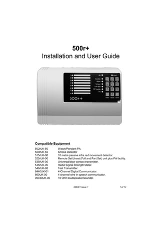
  • 2. 500r+ Introduction The 500r+ is a programmable Radio Alarm System designed specifically for domestic and small business premises. The 500r+ provides eight zones with PA on a dedicated zone. A basic system comprises a control unit with built in keypad, and associated radio detectors. The control unit houses the system electronics, power supply, battery, and 660 Speech Communicator (if fitted). A numeric keypad and two rows of Light Emitting Diodes (LEDs) allow the user and installer to operate the system. Up to six remote setting devices can also be used on the 500r+ to set or unset the system, and act as Personal Attack alarms. Each detector and remote setting device contains a digital identity code that the control unit ‘learns’ during installation. The code is one of over 16 million possibilities. This ensures that the control unit will not respond to any other detectors or remote setting switches apart from the ones it has learned. The radio operating frequency between the control unit receiver and the detectors is 418MHz with a bandwidth of 200kHz. The radio section is approved to MPT 1340. The 500r+ system is designed to meet the requirements of BS6799 Class “III” and complies with all current NACOSS codes of practice for domestic and small business Audible ONLY intruder alarm systems. The system can be certified by approved installers as a Wirefree “Class III” installation. 2 of 14 496361 Issue 1
  • 3. 500r+ Technical Specification Zones (500r+) Display Keypads Expansion Compliance Radio Section Radio section Log Control unit Siren Internal Sounder Battery 12V power Aux DC power Dimensions Weight Communicator Outputs 8 wirefree, plus PA. PA can use up to six 502r or 525r. LED. On-board + Remote Set/Unset using 525r, up to 6 per control unit. None. Product is CE tested to EN 50081-1 and EN 50082-1. Operating frequency 418 MHz at 200 kHz bandwidth. CE tested to I-ETS 300 339 (draft standard). 16 events. Yes (approx. 80db at 1 metre). 1 x 9040 16 Ohm loudspeaker (approx. 90db at 1 metre). 1.9(2.1)Ah lead acid gel type rechargeable. Control unit quiescent current 55mA. 500mA max at 12V in alarm state. h x w x d = 163 x 257 x 74 mm. 1.2 kg. 50mA max PA and Burg outputs for 660 Speech Communicator or 8440 Digital Communicator. Positive removed in alarm. Bell and Strobe (negative applied (SAB)) 500mA total output. 496361 Issue 1 3 of 14
  • 4. 500r+ Wiring External Bell Figure 9 shows an example of connections for a typical external bell (see the manufacturers instructions supplied with individual units for further information on wiring diagrams). Figure 9. Typical External Sounder Connections Make connections to the control unit and SAB module as follows: STR Negative trigger in alarm for strobe light. BELL Negative bell trigger. 12V Positive bell module hold off voltage (Supply). 0V Negative bell module hold off (Supply). TR Negative tamper return from bell module to control unit. Notes: 1. SAB shown for negative applied. 2. Link tamper return to 0V if no external bell is required. 3. Connect all bell wiring to the control unit with the exception of the bell trigger. The bell/siren will continue to ring from the on-board battery until the final connections are made after initial power-up. See ‘Programming - Initial Power Up’. 4 of 14 496361 Issue 1
  • 5. 500r+ Fitting a 660 or 8440 Communicator Fitting a 660 or 8440 Communicator Figure 10. 660 or 8440 Communicator Connections The output connectors available are: OP1 Burglar output - positive removed in alarm (+12V, 50mA max). OP2 PA output - positive removed in alarm (+12V, 50mA max). Fit the communicators inside the back casing. Locate the communicator toward the top left of the back box. Note: Do not connect the 12V supply to the communicator until after the initial power up. See ‘Programming’. 496361 Issue 1 5 of 14
  • 6. 500r+ Programming Initial Power Up Note: Before applying power to the control unit ensure that the bell trigger is not connected to any external sounders, or 12V supply connected to the 660 Speech Communicator (if fitted). 1. 2. 3. 4. 5. Close the control unit lid or defeat lid tamper. Apply mains power to the control unit. Key in the default user code (1234) if there is an alarm. Ignore any LEDs that are lit at this stage. Key in the engineer code (default 7890). The Standby LED flashes. Open the control unit lid or release control unit tamper. The a (Power) LED goes off and the Standby LED glows steadily. The control unit gives a double bleep. You are now in Programming mode. 6. Connect the battery and make any final wired connections (for example to the bell and 660 Speech Communicator). Learning Detectors (Command 81) You must make the control unit learn the identity of each detector in the system and link them to zones. To do this: 1. Enter programming mode if you have not done so already. 2. Enter 81 on the keypad. The Standby LED flashes. The LEDs of zones that already have detectors flash. The LEDs of zones with no detectors glow steadily. The contol unit uses the PA LED for any 502r or 525r’s. 3. Enter the number of the zone you want the control unit to learn (use 9 for a 502r or 525r). The LED of the zone you selected flashes, all the other zone LEDs go out (the PA LED flashes if you selected 9). 4. Point the activity LED of the detector at the Learn sensor on the control unit (marked by Learn). Hold the activity LED of the detector close to the sensor. Trigger the detector by operating the tamper, or press a button on the 502r or 525r. 5. 6 of 14 496361 Issue 1
  • 7. 500r+ Deleting Detectors The activity LED on the detector flashes, and transmits an identity code to the Learn sensor. The control unit gives a short double beep when it learns the code. 6. Repeat steps 3 to 5 for any other detectors you want the control unit to learn. Notes: 1. The default factory setting is Zone 1 as the Entry/Exit zone. 2. The control unit will not learn the same detector more than once. 3. The control unit can learn a total of six 502r or 525r’s in any combination. Each device uses the PA zone (9). Deleting Detectors (Command 82) If you wish to change detectors then the control unit cannot learn a new detector for a zone that is already in use. You must delete the existing detector first, as follows: 1. Enter programming mode if you have not already done so. 2. Enter 82 on the keypad. The Standby LED flashes. The LEDs of zones that already have detectors glow steadily. The LEDs of zones with no detectors stay off. The control unit uses the PA LED for any 502r or 525r’s. 3. Enter the number of the zone you want to delete (use 9 for 502r and 525r’s). The LED of the zone you selected flashes. Note: The control unit deletes all 502r and 525r’s if you select ‘9’. 4. Press 8 on the keypad. The LED of the zone you selected goes out and the control unit gives a double bleep. 5. Repeat steps 2 to 4 for any other detectors you want to delete. Programming Commands To change the factory default program, use the commands listed in this section as follows: 1. Enter the command number. The Alarm LED flashes if the current program is the factory default. 2. 3. Enter one or more digits to give the new progam. Press Reset. 496361 Issue 1 7 of 14
  • 8. Program Commands 500r+ The control unit will give a double bleep to show it has accepted the command. If you enter the command incorrectly the control unit gives a single low bleep. When delivered from the factory, the control unit is programmed with standard defaults for each command. A “Y ” in the right hand column of the table shows the default. To change: Key in: Followed by: Default Engineering Walk Test 71 (see “5. Testing”) Change User Code 72 New user code (four digits) 1234 View Log 73 (see “Testing”) Test Strobe 74 (see “Testing”) Test Siren 75 (see “ Testing”) Add Detector 81 (see ”Learning Detectors”) none Delete Detector 82 (see “Deleting Detectors”) Burg O/P Follows Bell 84 1 + Reset = Yes Omit + Reset =No Y Entry/Exit Time Bell Duration Strobe follows bell 86 A number 10 to 99 seconds + Reset. 30s 87 A number 01 to 20 minutes + Reset. 20 mins 88 1 + Reset = Yes. Engineer Code Remote Unset 89 New four digit code. Do not use 0 (zero) for the first digit. 7890 90 1 + Reset = No entry timer required. Bell Delay 91 A number 01 to 30 minutes + Reset. System Reset 92 1 + Reset = Engineer only. Entry Route Zone 93 Zone number(s) 2 to 8 + Reset. PA Response 94 1 + Reset = Silent. Omit Allowed 95 1 + Reset = No. Additional E/Exit Zones 96 Zone number(s) 2 to 8 + Reset. Tamper response 97 1 + Reset = Full alarm in user mode. Omit + Reset = Continuous. Omit + Reset = Needs entry timer. Omit + Reset + Reset = nil. Omit + Reset = Customer reset. Omit + Reset = None. Omit + Reset = Audible. Omit + Reset = Yes. Omit + Reset = Zone 1 only. Omit + Reset = Internal alarm in user mode. Restore Factory Defaults Leave Programming 8 of 14 98 Omit + Omit + Omit 99 Reset 496361 Issue 1 Y Y Y Y Y Y Y Y Y
  • 9. 500r+ Restoring Factory Default Program Restoring Factory Default Program (Command 98) If you want to restore all the programming to the original factory defaults, then: 1. Enter 98. The control unit bleeps once every second. 2. Press Omit three times. The control unit gives a double bleep, erases all the programs the user and previous engineers have entered, and restores the original factory defaults. Note: The control unit will still remember any detectors that it has learned. Leaving Programming Mode (Command 99) The control unit will stay in programming mode until you enter a command to return it to user mode, as follows: 1. Close control unit lid. 2. Enter 99. The a and Standby LEDs glow steadily. The control unit is now in user mode. To Re-enter Programming Mode 1. 2. Make sure the control unit is unset. Enter Engineer Code. The Standby LED flashes. 3. Open the control unit lid. The control unit gives a double bleep, the a LED goes out and the Standby LED glows steadily. The control unit is now in programming mode. Clearing a Control unit For a New User To remove all programming, including detectors and Engineer and User codes (perhaps to reuse the control unit with another user) then, while the control unit is unset: 1. Open the lid. 2. Remove the mains supply and disconnect the Battery. 3. Short together the two middle CLR pins on the NVM Reset pin block and reconnect battery supply. The control unit restores all its programming to the factory default settings, and deletes all detectors. 496361 Issue 1 9 of 14
  • 10. Changing the User Code 4. 5. 6. 7. 500r+ Remove the short after two seconds. Restore the mains supply. Close the lid. Enter 1234 and press Reset. Note: To restore all the programming apart from the learnt detectors, repeat steps 1 to 7 above, but at 3. short together the top two LOAD DFLTS pins. Changing the User Code You can change the user access code while in programming mode. To do this: 1. Enter programming mode. 2. Enter 7 2. The LEDs for zones 5, 6, 7 and 8 light up. 3. Key in the new user code (four digits). Each time you key in a digit of the user access code one of the 5, 6, 7, or 8 LEDs goes out. 4. Leave programming mode. 5. Testing Testing Detectors Make sure the system is in programming mode. 1. Enter 71. All LEDs light for 2 seconds, and then the control unit enters walk test mode. 2. Activate each 502r, 525r (PA function only), and detector. You may also test detector tampers. When the control unit receives the detector it gives a chime tone and turns the relevant zone LED on for five seconds. The control unit turns on the Alarm and Tamper LEDs when you activate the tampers. When you activate the 502r Watch Pendant or the PA function on the 525r Remote Setting Device the control unit gives a chime tone and lights the PA LED for five seconds. 3. Press Reset to end the walk test. PIR Testing and Lockout In normal use the 515r uses a three minute lockout timer in order to extend battery life.The lockout timer works like this: 10 of 14 496361 Issue 1
  • 11. 500r+ Testing Siren and Strobe a) The unit detects movement, signals the panel, and starts the lockout timer. b) If the unit detects movement while the lockout timer is running, then it restarts the lockout timer but DOES NOT signal the panel. c) When the lockout timer expires the unit signals the panel the next time it detects movement. If you want to test a 515r PIR in normal use you should leave the protected area and wait at least four minutes between activations. To make testing easier the detector changes the lockout period to 10 seconds for the first half hour after you put the batteries in, or after you trigger its tamper. Note: Make sure the control unit is in programming mode before you open or move any of the detectors. This will avoid setting the tamper alarm off. Testing Siren and Strobe Make sure the system is in programming mode. 1. Enter 75. The control unit activates the siren. 3. Press Reset. The control unit silences the bell (the control unit will silence the bell after 30 seconds if you do not press Reset). 4. Enter 74. The control unit triggers the strobe. 6. Press Reset. The control unit switches the strobe off (the control unit will switch the strobe off after 30 seconds if you do not press Reset). Examining the Log The control unit keeps a record of the last 16 events. You can examine this record, starting with the most recent event, as follows: 1. Make sure the system is in programming mode. 2. Enter 73. The display LEDs show the most recent event. 4. Press 3 repeatedly. The display shows an earlier event in the list each time you press 3. The control unit gives a low tone when it reaches the end of the list. 5. Press Reset. 496361 Issue 1 11 of 14
  • 12. 500r+ The system goes back to program mode (the control unit will switch itself back to program mode after 30 seconds if you do not press any key). 6. Fault Finding Symptom Response • FAULT TONE AND a FLASHES CONTINUOUSLY. • Mains supply has failed, control unit operating from battery only. (If Fault tone present mains failed over 1 hour ago.) • Check mains connection and fuse. • TAMPER FLASHES, CONTROL UNIT WILL NOT • Check connections and ensure external sounder tamper switch is RESET. fully closed. Ensure cover on External sounder is secure. FAULT TONE, LOW BATT AND PA LED ON. • Low battery in 502r or 525r indicated - replace battery. FAULT TONE, LOW BATT AND ZONE LED ON. • Low battery in detector indicated - replace battery. • CANNOT LEAVE PROGRAMMING MODE. • Tamper on steadily - control unit tamper not closed. (System can still be armed with low battery indication.) (System can still be armed with low battery indication.) • TAMPER (AND POSSIBLY ZONE) LED ON. • Tamper flashing - External sounder tamper not closed. • Zone LED with Tamper - detector open or not screwed down firmly. • Clear fault. Press Reset (Standby will glow steadily). • Key in 99 (a and Standby glow steadily). • RF TROUBLE LED FLASHING. • Control unit detecting interference on same frequency as detectors. • Wait till RF Trouble goes out. If problem persists, call Scantronic Technical Support. • PIR DOES NOT DETECT MOVING PERSON (NO RED LIGHT). • To save power, after each activation the PIR ‘sleeps’ for three minutes. Any movement during the three minutes will extend the sleep period by another three minutes. See PIR Installation Guide. • Check detector battery. • PIR DOES NOT APPEAR TO TRANSMIT IMMEDIATELY WHEN DETECTION TAKES • This is normal. The PIR may take up to two seconds (variable) to transmit after detecting a moving person. PLACE. • WHEN DOOR OPENED, TAMPER AND ZONE LEDS FLASH • Detector case not properly closed, or not screwed down fully to close front or back tamper switch. AND INTERNAL ALARM SOUNDS. • SAB WILL NOT STOP RINGING. • SAB not receiving power. • Check fuse F1. • Check tamper switch on external sounder. • Ensure cover on External sounder is secure. 12 of 14 496361 Issue 1
  • 13. 500r+ User Commands First to Alarm Indication When several alarm events occur before the user can reset the system, the control unit indicates which event occured first. It does this by flashing LEDs lit by the first event, and lighting LEDs steadily for subsequent events. For example, if the control unit detects a tamper on zone 2 followed by a violation on zone 3, then the Tamper and zone 2 LEDs flash, while the Alarm and zone 3 LEDs glow steadily. User Commands From the Keypad Full Set User code + ENTER. Unset User code. Part Set User code + OMIT + zone number + ENTER. Silence Bells User code. Reset Press RESET. Change User Code User code + 2 + old code + new code. Read log User code + 3 + 3 (to read earlier events) + 0 (to end log). Walk Test User code + 1 + activate detectors + 0 to end test. Test Bell User code + 5 + 0 to end test. Test Strobe User code + 4 + 0 to end test. From the 525 Remote Setting Device Full Set Press Arm. Part Set Press Night (system sets omitting any zones previously omitted using the keypad). Unset Press Off. PA Press Arm and Off together. 496361 Issue 1 13 of 14
  • 14. 14 of 14 496361 Issue 1